

OPERATING INSTRUCTIONS
MIXER POWER AMPLIFIER BG-1015
BG-1030
BG-1060
BG-1120
Please follow the instructions in this manual to obtain the optimum results from this unit.
We also recommend that you keep this manual handy for future reference.

SAFETY PRECAUTIONS
• Be sure to read the instructions in this section carefully before use.
• Make sure to observe the instructions in this manual as the conventions of safety symbols and messages
regarded as very important precautions are included.
• We also recommend you keep this instruction manual handy for future reference.
Safety Symbol and Message Conventions
Safety symbols and messages described below are used in this manual to prevent bodily injury and property
damage which could result from mishandling. Before operating your product, read this manual first and
understand the safety symbols and messages so you are thoroughly aware of the potential safety hazards.
WARNING
Indicates a potentially hazardous situation which, if mishandled, could
result in death or serious personal injury.
Indicates a potentially hazardous situation which, if mishandled, could
result in moderate or minor personal injury, and/or property damage.
WARNING
CAUTION
2
IMPORTANT SAFETY INSTRUCTIONS
· Be sure to read these instructions in this section carefully before use.
· Heed all warnings and follow all instructions.
· Keep these instructions handy for reference at any time.
• Do not block any of the ventilation openings. Install in accordance with the manufacturer's instructions.
• Do not install near any heat sources such as radiators, heat registers, stoves, or other apparatus (including
amplifiers) that produce heat.
• Do not defeat the safety purpose of the polarized or grounding type plug. A polarized plug has two blades
with one wider than the other. A grounding type plug has two blades and a third grounding prong. The wide
blade or the third prong is provided for your safety. When the provided plug does not fit into your outlet,
consult an electrician for replacement of the obsolete outlet.
• Protect the power cord from being walked on or pinched particularly at plugs, convenience receptacles, and
the point where they exit from the apparatus.
• Only use the attachments or accessories specified by the manufacturer.
• Use only with a cart, stand, tripod, bracket, or table specified by the manufacturer, or sold with the
apparatus. When a cart is used, use caution when moving the cart/apparatus combination to avoid injury
from tip-over.
• Unplug this apparatus during lightning storms or when unused for long periods of time.
• Refer all servicing to qualified service personnel. Servicing is required when the apparatus has been
damaged in any way, such as power supply cord or plug is damaged, liquid has been spilled or objects have
fallen into the apparatus, the apparatus has been exposed to rain or moisture, does not operate normally, or
has been dropped.
• Do not use this apparatus near water.
• Clean only with a dry cloth.
When Installing the Unit
• Do not expose the unit to rain or an environment
where it may be splashed by water or other liquids,
as doing so may result in fire or electric shock.
• Use the unit only with the voltage specified on the
unit. Using a voltage higher than that which is
specified may result in fire or electric shock.
• Do not cut, kink, otherwise damage nor modify the
power supply cord. In addition, avoid using the
power cord in close proximity to heaters, and never
place heavy objects -- including the unit itself -- on
the power cord, as doing so may result in fire or
electric shock.

3
• Be sure to replace the unit's terminal cover after
connection completion. Because high voltage is
applied to the speaker terminals, never touch these
terminals to avoid electric shock.
• Avoid installing or mounting the unit in unstable
locations, such as on a rickety table or a slanted
surface. Doing so may result in the unit falling
down, causing personal injury and/or property
damage.
When the Unit is in Use
• Should the following irregularity be found during
use, immediately switch off the power, disconnect
the power supply plug from the AC outlet and
contact your nearest TOA dealer. Make no further
attempt to operate the unit in this condition as this
may cause fire or electric shock.
· If you detect smoke or a strange smell coming
from the unit.
· If water or any metallic object gets into the unit
· If the unit falls, or the unit case breaks
· If the power supply cord is damaged (exposure of
the core, disconnection, etc.)
· If it is malfunctioning (no tone sounds.)
• To prevent a fire or electric shock, never open nor
remove the unit case as there are high voltage
components inside the unit. Refer all servicing to
your nearest TOA dealer.
• Do not place cups, bowls, or other containers of
liquid or metallic objects on top of the unit. If they
accidentally spill into the unit, this may cause a fire
or electric shock.
• Do not insert nor drop metallic objects or
flammable materials in the ventilation slots of the
unit's cover, as this may result in fire or electric
shock.
When Installing the Unit
• Never plug in nor remove the power supply plug
with wet hands, as doing so may cause electric
shock.
• When unplugging the power supply cord, be sure
to grasp the power supply plug; never pull on the
cord itself. Operating the unit with a damaged
power supply cord may cause a fire or electric
shock.
• When moving the unit, be sure to remove its power
supply cord from the wall outlet. Moving the unit
with the power cord connected to the outlet may
cause damage to the power cord, resulting in fire or
electric shock. When removing the power cord, be
sure to hold its plug to pull.
• Avoid installing the unit in humid or dusty locations,
in locations exposed to the direct sunlight, near the
heaters, or in locations generating sooty smoke or
steam as doing otherwise may result in fire or
electric shock.
When the Unit is in Use
• Do not place heavy objects on the unit as this may
cause it to fall or break which may result in
personal injury and/or property damage. In
addition, the object itself may fall off and cause
injury and/or damage.
• Make sure that the volume control is set to
minimum position before power is switched on.
Loud noise produced at high volume when power is
switched on can impair hearing.
• Do not operate the unit for an extended period of
time with the sound distorting. This is an indication
of a malfunction, which in turn can cause heat to
generate and result in a fire.
• Contact your TOA dealer as to the cleaning. If dust
is allowed to accumulate in the unit over a long
period of time, a fire or damage to the unit may
result.
• If dust accumulates on the power supply plug or in
the wall AC outlet, a fire may result. Clean it
periodically. In addition, insert the plug in the wall
outlet securely.
• Switch off the power, and unplug the power supply
plug from the AC outlet for safety purposes when
cleaning or leaving the unit unused for 10 days or
more. Doing otherwise may cause a fire or electric
shock.
CAUTION
ATTENTION
L'appareil ne doit pas être exposé aux éclaboussures ou écoulements et tous objets remplis de liquide, tels
que vases, ne doivent pas être sur l’appareil.

4
TABLE OF CONTENTS
1. GENERAL DESCRIPTION ............................................................................. 5
2. FEATURES .......................................................................................................... 5
3. NOMENCLATURE AND FUNCTIONS
Front ......................................................................................................................... 6
Rear .......................................................................................................................... 7
4. INPUT CONNECTIONS ................................................................................... 8
5. OUTPUT CONNECTIONS .............................................................................. 9
6. PLUG-IN MODULE INPUT PORT
6.1. Module Installation ............................................................................................ 9
6.2. Module Selector Switch Settings ...................................................................... 10
7. EQUIPMENT SETTINGS
7.1. Mute Function
7.1.1. Mute operation A .................................................................................... 10
7.1.2. Mute operation B .................................................................................... 11
7.2. TEL Input Impedance Selection ....................................................................... 11
7.3. AUX, PROGRAM, MODULE (BGM) Output Selection ..................................... 12
7.4. Phantom Power On/Off Setting for Microphone Input ...................................... 12
7.5. Changing MIC and PROGRAM Input Types
7.5.1. MIC input ................................................................................................ 12
7.5.2. Program input ........................................................................................ 13
8. INSTALLATION ................................................................................................. 13
9. RACK MOUNTING ........................................................................................... 13
10. CONTROL SETTINGS .................................................................................... 14
11. DIMENSIONAL DIAGRAM ............................................................................ 14
12. BLOCK DIAGRAM ........................................................................................... 15
13. SPECIFICATIONS ............................................................................................ 16
Accessories ............................................................................................................. 16
Optional products .................................................................................................... 16

5
1. GENERAL DESCRIPTION
TOA's BG-1015, BG-1030, BG-1060, and BG-1120 Mixer Power Amplifiers can mix up to a total of 5
independent input signals. Power output is rated at 15 W for the BG-1015, 30 W for the BG-1030, 60 W for the
BG-1060, and 120 W for the BG-1120. All units are ideal for use in sound systems requiring small power
outputs.
2. FEATURES
• 3 balanced inputs, 1 unbalanced input, and 1 module input
• Phantom-powered microphone input
• Telephone paging input
• Compatible with all 900 Series modules (except for mute buss functions)
• Wide frequency response ranging from 50 Hz to 20 kHz
• Low distortion and low noise level
• Excellent output regulation
• Three different speaker outputs: 4 Ω, 25 V, and 70 V
• MOH (Music On-Hold) output: 1 V, 600 Ω
• 1W output terminal: 8 Ω
• Independent bass and treble controls
• Input and output terminals for connection of signal processors
• Two different mute functions
• Overcurrent and thermal protection circuitries
• Compact and lightweight
• Desktop or 19" rack mountable
6
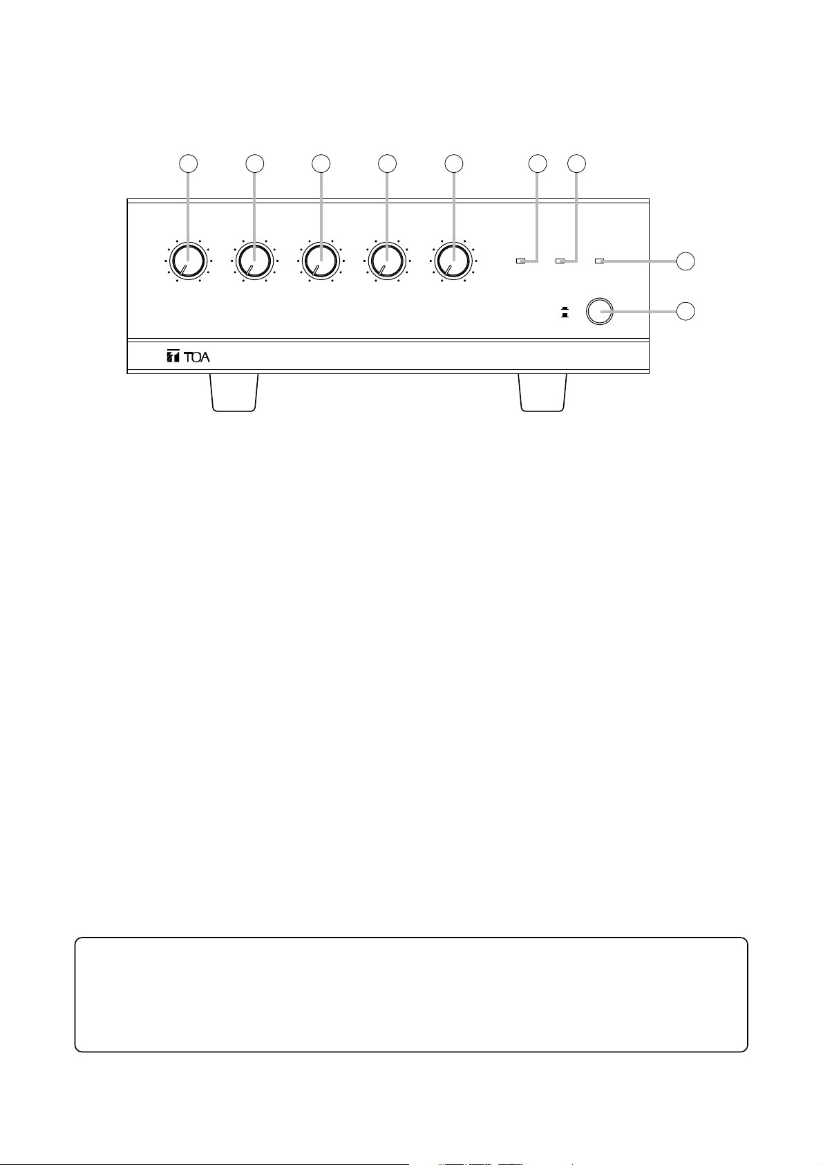
3. NOMENCLATURE AND FUNCTIONS
[Front]
1. Power switch
Press to turn ON the power. Press again to turn
the power OFF.
Note
Amplifier operation is enabled about 3 seconds
after the power switch is pressed.
2. Power indicator
Lights green when the power is switched on.
3. Signal level indicator
Lights green when the speaker output signal level
exceeds 20 dB.
4. Peak indicator
Lights when the output signal level exceeds the
point at which the signal begins to distort. If this
indicator remains lit, reduce the volume at each
volume control so that the indicator only lights
momentarily.
5. Microphone input volume control
Adjusts the microphone input volume. Turn
clockwise to increase and counterclockwise to
decrease.
6. Telephone paging input volume control
Adjusts the telephone paging input volume. Turn
clockwise to increase and counterclockwise to
decrease.
7. Program input volume control
Adjusts the Program input volume. Turn clockwise
to increase and counterclockwise to decrease.
8. AUX input volume control
Adjusts the AUX input volume. Turn clockwise to
increase and counterclockwise to decrease.
9. Module input volume control
Adjusts the Module input volume. Turn clockwise
to increase and counterclockwise to decrease.
Protection function to be noted on operation
When the temperature of unit's internal heat sink exceeds the specified limit, the protection circuit is
activated and the output is disconnected from the circuit. Output is automatically restored when the heat
sink cools down below the temperature limit.
3
45 6 7 8 9
MIC
100
TEL
010 0
INTEGRATED AMPLIFIER BG-1120
PROGRAM
10 100010
AUX MODULE
This figure represents the BG-1120.
SIGNAL
POWERPEAK
2
ON
OFF
1
7
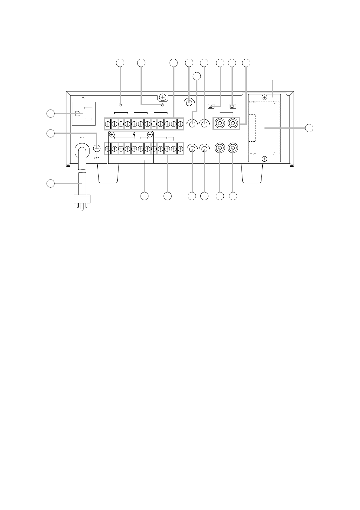
10. Power cord
Connect this cord to an AC outlet of 120 V AC.
11. Ground terminal
A functional ground terminal.
12. AC outlet [UNSWITCHED]
Continuously supplies up to 500 W of AC power
to connected external equipment.
13. Breaker [UNIT]
Cuts off the AC power to the unit when its input
current exceeds the allowable value.
Note
The yellow button in the breaker pops out to
indicate that the breaker has tripped. After
turning off the power and eliminating the cause
of the breaker trip, press the button to reset the
breaker.
14. Breaker [OUTLET]
Cuts off the AC power supply from the AC outlet
if current output exceeds 4 A.
Note
The yellow button in the breaker pops out to
indicate that the breaker has tripped. After
turning off the power and eliminating the cause
of the breaker trip, press the button to reset the
breaker.
15. Input terminal block
Used for connection of MIC, TEL and
PROGRAM inputs. (Refer to p. 8.)
16. Output terminal block
Used for connection of speaker outputs, 1 W
output, MOH (Music On-Hold) output, and Mute
control signals. (Refer to p. 9 and p. 10.)
17.Sensitivity control
Adjusts the sensitivity of the mute circuit. Rotate
clockwise to increase sensitivity, and
counterclockwise to reduce sensitivity.
18. Bass control
Adjusts the bass frequency band level of speaker
outputs for MODULE (BGM), PROGRAM, and
AUX input signals. Rotate clockwise to increase
bass output, and counterclockwise to reduce it.
The center position provides flat characteristics.
19. Treble control
Adjusts the treble frequency band level of
speaker outputs for MODULE (BGM),
PROGRAM, and AUX input signals. Rotate
clockwise to increase treble output, and
counterclockwise to reduce it. The center
position provides flat characteristics.
[Rear]
12
11
10
120V 60Hz
MAX 500W
UNSWITCHED
120V 60Hz
150W
13 14 15
UNIT
BREAKER
PUSH
RESET
4 A
PROGRAM
GCOM
HOT G
OUTPUT 120 W
COM 4Ω 70V25V 8Ω
CLASS 2 WIRING
TEL
COM
HOT
OUTPUT 1 W
COM
OUTLET
BREAKER
4 A
600Ω G
28
COMG
MOH
COM
22 23 24
1917
18
SENSE
PUSH
RESET
MUTE
NC
010
BASS
–+–
OUTPUT 1 W
20
MIC
HOT
16
MUTE
A0BBGM
TREBLE
0
+
MOH
100
100
21
PAGE
AUX
PREAMP
OUT
25 26
MODULE
POWER
IN
Blank panel
27
This figure represents the BG-1120.

8
20. 1 W output volume control
Adjusts the 1 W OUTPUT level. Rotate clockwise
to increase and counterclockwise to decrease.
21. MOH output volume control
Adjusts the MOH (Music On-Hold) output signal
level. Rotate clockwise to increase and
counterclockwise to decrease.
22. Mute selector switch
Changes the type of mute operation.
(Refer to p. 10.)
23. Module selector switch
Selects the output terminal for the module signal.
Set the switch to the PAGE position when using
the paging module, and to the BGM position
when using the BGM module.
24. AUX input terminals (2P RCA pin jack)
An internal mixing type of jack.
Used for connection of external equipment input
signals. (Refer to p. 8.)
25.Preamplifier output terminal [PREAMP OUT]
Used for connection of output signals to external
signal processing equipment such as limiters and
equalizers.
26. Power amplifier input terminal [POWER IN]
Used for connection of input signals from
external signal processing equipment such as
limiters and equalizers.
27.Module input port
Optional 900 Series modules can be installed
here.
Note
For details concerning 900 Series modules,
contact your nearest TOA dealer.
28. Terminal cover
Make sure that the terminal cover is reattached
after speaker output terminal connection
completion.
4. INPUT CONNECTIONS
[MIC input connections]
[TEL and PROGRAM input connections]
[AUX input connections]
G COM HOT
G COM HOT
H
C
E
H
Input source
C
E
MIC
AUX
H
Input source
E
H
Input source
E

9
5. OUTPUT CONNECTIONS
[Output terminals]
Each amplifier has 3 speaker outputs: 4 Ω, 25 V and 70 V. Use only one of these outputs for connection.
Class 2 wiring may be used.
Note: The impedance in the figure below represents the total impedance of the speaker system.
[MOH output connections]
The MOH output is rated at 1 V/600 Ω
[OUTPUT 1 W output connections]
The OUTPUT 1 W output is rated at 1 W/8 Ω
6. PLUG-IN MODULE INPUT PORT
A single port for TOA plug-in modules is located on the unit's rear panel. Any 900 Series plug-in module can
be inserted into this port.
Note: Consult your nearest TOA dealer for selection of appropriate module types.
Be sure to turn off the power before performing the following operations:
6.1. Module Installation
Step 1. Remove the blank panel covering the module
slot on the rear panel.
Step 2. Align the module board with the top and
bottom guide rails, and press in.
Step 3. Using the screws supplied with the module,
secure the module to the rear panel.
COM 4Ω
25V 70V COM 4Ω
4 Ω
600Ω COM G
25V 70V
E
C
H
COM 4Ω
5.2 Ω (BG-1120)
10.4 Ω (BG-1060)
21 Ω (BG-1030)
42 Ω (BG-1015)
25 V line
25V 70V
8Ω COM
40.8 Ω (BG-1120)
81.7 Ω (BG-1060)
163 Ω (BG-1030)
330 Ω (BG-1015)
70 V line
8Ω
Module mounting screw (supplied with the module)
Mixer power amplifier
Guide rail
900 Series plug-in module

10
6.2. Module Selector Switch Settings
Set the rear panel-mounted Module Selector Switch to either the PAGE or BGM position, depending on the
output terminal to which the module signal is to be sent.
PAGE: Signals from the installed module are only sent to the
speaker outputs.
BGM: The terminal to which the signal from the module is to
be output differs depending on jumper wire settings
inside the unit. (Refer to p. 12.)
Set both the bass and treble controls to the center position when using the equalizer module.
Caution: Make sure that the supplied blank panel is placed over the connector port when the port is not in
use.
7. EQUIPMENT SETTINGS
7.1. Mute Function
The unit features 2 different mute functions, A and B. Mute A or
B can be selected with the rear panel-mounted Mute Selector
Switch.
7.1.1. Mute operation A
The mute function can be activated either by the TEL, MIC, or MODULE (PAGE) input signal, or by shorting
the rear panel-mounted mute terminals.
[Mute signal settings]
Input signals to activate the mute function can be selected by the internal jumper wire settings. The TEL, MIC,
and MODULE (PAGE) input signals are all factory-preset (Jumpers JP207, JP208, and JP209 are set) as
muting signals.
Cut off the jumper wire corresponding to the input signal to be disabled for muting.
In any case, shorting the rear-mounted Mute terminals can also actuate the mute function.
Note
If Module Input is selected, the mute function can only be used when the Module Selector Switch is set to the
PAGE position.
Caution: Be sure to leave settings to a qualified technician.
PAGE BGM
MODULE
Module selector switch
MUTE
AB
Mute selector switch
JP208
JP207
JP209
T203
T202 T201
Preamplifier board
TEL
MIC
MOD
11
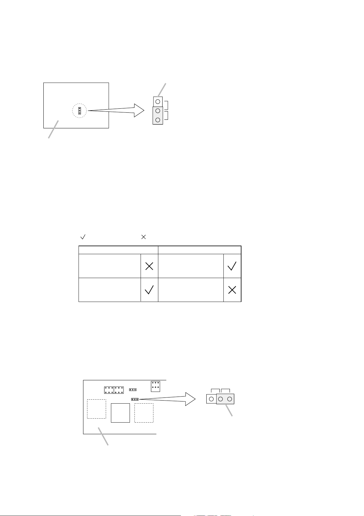
[Muted signal settings]
Use the unit's internal jumper switch JP301 to select the signal to be muted. Select either the input signal from
the TEL, MIC, and MODULE (PAGE) terminals or from the AUX, PROGRAM, and MODULE (BGM) terminals
as the signal to be muted.
7.1.2. Mute operation B
The mute function can be controlled by way of the rear panel-mounted Mute terminal.
Note: The mute function cannot be controlled by means of an input signal.
[Mute terminal]
Close
MIC
TEL
MODULE (PAGE)
AUX
PROGRAM
MODULE (BGM)
Open
MIC
TEL
MODULE (PAGE)
AUX
PROGRAM
MODULE (BGM)
: Channel is ON. : Signal is muted.
7.2. TEL Input Impedance Selection
The impedance is factory-preset to 10 kΩ. To switch to 600 Ω, change the position of the unit's internal jumper
switch JP204.
Jumper switch JP301
PAGE: TEL, MIC, MODULE ( PAGE)
BGM: AUX, PROGRAM, MODULE ( BGM)
Preamplifier output board
Note: Selection is factory-preset to the input from AUX, PROGRAM,
and MODULE (BGM) terminals.
10 kΩ600 Ω
T203
T202 T201
Jumper switch JP204
Preamplifier board

12
7.5. Changing MIC and PROGRAM Input Types
Both MIC and PROGRAM inputs can be changed from electronically-balanced to transformer-balanced types
in the procedures as follows.
7.5.1. MIC input
• Install an optional IT-450 Line Transformer in the specified location on the printed circuit board.
• Cut off the JP202 and JP203 jumper wires.
7.4. Phantom Power On/Off Setting for Microphone Input
The phantom power is set for ON or OFF by the unit's internal jumper switch JP201.
It is factory-preset for OFF.
7.3. AUX, PROGRAM, MODULE (BGM) Output Selection
Operations shown in the following table can be enabled with the unit's internal jumper settings.
[OUTPUT 15 W/30 W/60 W/120 W] [OUTPUT 1 W, MOH]
Jumpered AUX: ON
Cut AUX: OFF
Jumpered PROGRAM: ON
Cut PROGRAM: OFF
Jumpered MODULE (BGM): ON
Cut MODULE (BGM): OFF
JP210
JP211
JP212
Jumpered AUX: ON
Cut AUX: OFF
Jumpered PROGRAM: ON
Cut PROGRAM: OFF
Jumpered MODULE (BGM): ON
Cut MODULE (BGM): OFF
JP213
JP214
JP215
JP215: MODULE (BGM)
JP213: AUX
JP214: PROGRAM
[OUTPUT 15 W/30 W/60 W/120 W] [OUTPUT 1 W, MOH]
JP212: MODULE (BGM)
JP211: PROGRAM
JP210: AUX
T203
Preamplifier board
T202 T201
Preamplifier board
ONOFF
T203
T202 T201
Jumper switch JP201
JP202
JP203
Preamplifier board
T203
T202
Line Transformer IT-450

13
7.5.2. Program input
• Install an optional IT-453A Line Transformer in the specified location on the printed circuit board.
• Cut off the JP205 and JP206 jumper wires.
8. INSTALLATION
Keep the unit's all sides at least 10 cm away from
objects that may obstruct air flow to prevent the
unit's temperature from rising.
9. RACK MOUNTING
To mount the amplifier in a standard 19" equipment rack, use the optional MB-1000 Rack Mouting Kit.
Attach the MB-1000 to the amplifier using the supplied 4 screws. When using other screws, ensure that each
screw is shorter than 16 mm.
JP206
JP205
T202 T201
Line Transformer
Preamplifier board
IT-453A
At least
10 cm
MIC
100
INTEGRATED AMPLIFIER BG-1120
TEL
010 0
PROGRAM
AUX MODULE
10 100010
SIGNAL
POWERPEAK
ON
OFF
At least
10 cm
At least
10 cm
Amplifier
Amplifier
Amplifier
Amplifier
M4 x 16 Machine screw included in MB-1000
MB-1000
PF-511 Perforated Panel (1-unit size)
Note
Mount the Perforated Panel PF-511 above and below each amplifier
for ventilation inside the rack.
About the perforated panel, consult your TOA dealer.
Amplifier
14
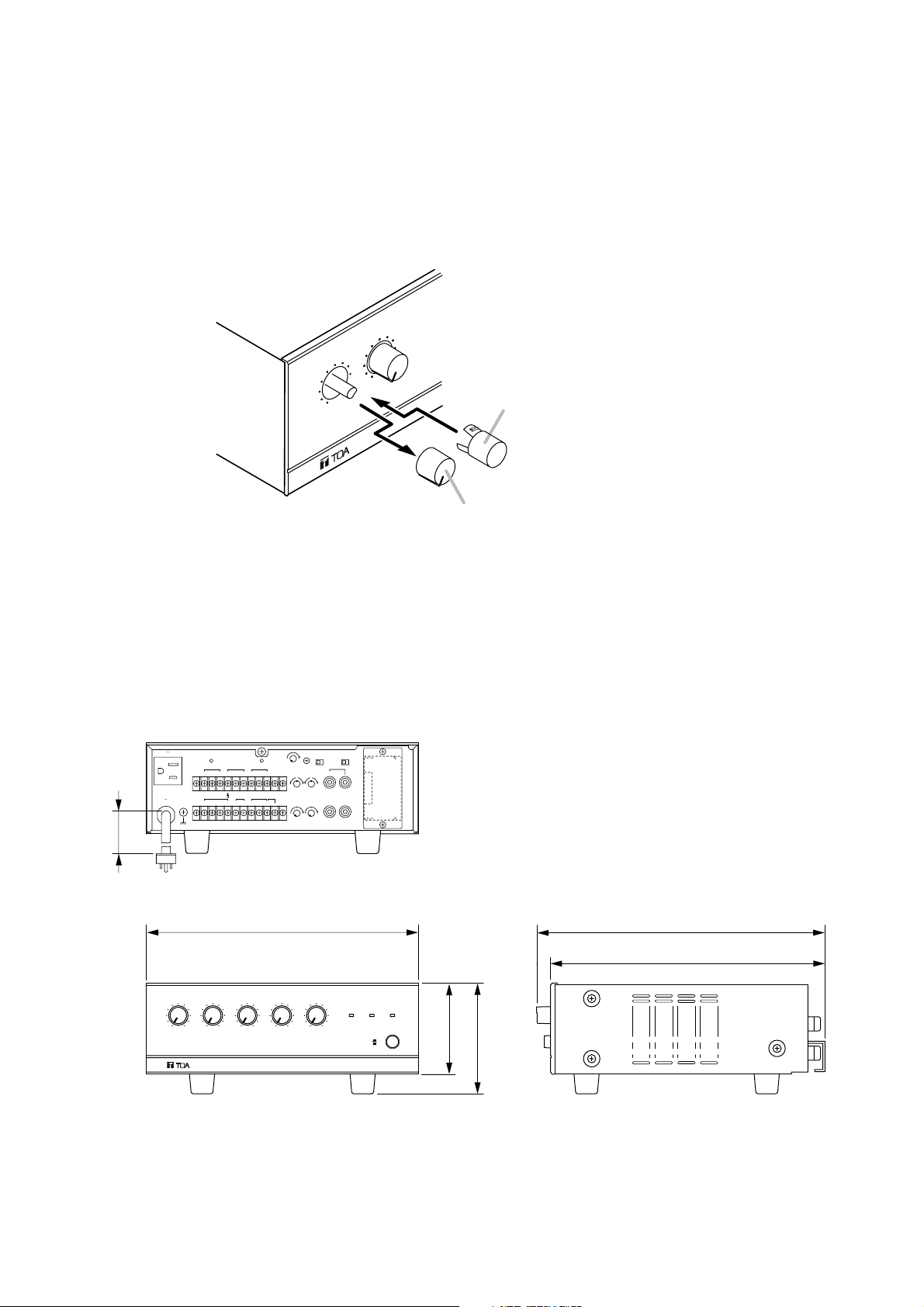
10. CONTROL SETTINGS
Output levels are adjustable with individual volume controls. For music play or announcement, adjust the
corresponding volume control so that the signal indicator lights intermittently. Note that the sound quality is
downgraded when the peak indicator remains lit.
To prevent the accidental change of the settings of input volume controls, remove their knobs after setting
them to the desired position and attach the volume control covers instead.
11. DIMENSIONAL DIAGRAM
(Applicable to all models)
L
E
T
C
I
M
10
010 0
TED AMPLIFIER BG-1120
GRA
TE
IN
1800
120V 60Hz
MAX 500W
UNSWITCHED
120V 50Hz
UNIT
PUSH
BREAKER
RESET
1.25A
PROGRAM
GCOMHOT G COM
OUTPUT 15W
40W
COM 4Ω 70V25V 8Ω
CLASS 2 WIRING
TEL
OUTPUT 1W
SENSE
OUTLET
PUSH
BREAKER
RESET
4A
MIC
HOT
HOT
COMG
MUTE
MOH
COM
600Ω G
COM
MUTE
0
BASS
NC
– +
OUTPUT 1W
0
MODULE
10
A0B
PAGE BGM
TREBLE
AUX
0
– +
PREAMP
POWER
OUT
IN
MOH
100
10
model BG-1015
Volume control cover (Accessory)
Volume control knob
Unit: mm
MIC0TEL
10
010 010
INTEGRATED AMPLIFIER BG-1015
PROGRAM
264
AUX
280
266.5
MODULE
SIGNAL
POWERPEAK
100
010
ON
OFF
88.4
107.4

15
12. BLOCK DIAGRAM
PAGE
JP301
Mute
BGM
Preamp OUT
(Preamplifier Output)
Power IN
(Power Amplifier Input)
70
O.T.
Peak Signal
Mute
Power
Output 15 W/30 W/
60 W/120 W
4Ω
25
Output 1 W 1 W/8 Ω
COM.
Power
MOH output
O.T.
1 V/600 Ω
AC 120 V
60 Hz
Breaker
Breaker
Power S.W.
A.C. Outlet
Mic Vol.
JP207
Mute
Tel Vol.
JP208
Mute Cont.
B
A
JP209
Mute Cont.
Mute selector
Tone
PAGE
JP212
PAGE
BGM
Bass Treble
JP215
BGM
Output 1W Vol.
JP211
JP214
Program Vol.
MOH Vol.
JP210
AUX Vol.
P.T
Power
JP213
Mic
–60 dB/600 Ω
Balanced
I.T.
Option EBA
Phantom Power (DC 24 V)
JP201
ON
OFF
Tel
Module
Program
–10 dB/10 kΩ
I.T.
AUX
–10 dB/47 kΩ
I.T.
600 Ω
10 kΩ
JP204
–20 dB/10 kΩ
Mute
OUT
IN
Module
Option EBA

BG-1015 BG-1030 BG-1060 BG-1120
120 V AC, 60 Hz
15 W 30 W 60 W 120 W
50 W 80 W 160 W 260 W
40 W 60 W 100 W 150 W
50 – 20,000 Hz
0.05% at 1 kHz, rated output
Mic: –60 dB*1, 600 Ω, electrically balanced, M3 screw terminal*
2
Tel: –20 dB*1, 10 kΩ/600 Ω, balanced, M3 screw terminal*
2
Program: –10 dB*1, 10 kΩ, electrically-balanced, M3 screw terminal*
2
Aux: –10 dB*1, 47 kΩ, unbalanced, 2P RCA pin jack (internal mixing)
Module: –20 dB*1, 10 kΩ, unbalanced, card edge connector
Power IN: 0 dB*1, 10 kΩ, unbalance, RCA pin jack
Mute: M3 screw terminal*
2
Main: 4 Ω, 25 and 70 V, balanced, M3 screw terminal*
2
Sub: 1 W/8 Ω, unbalanced, M3 screw terminal*
2
MOH: 0 dB*1, 600 Ω, balanced, M3 screw terminal*
2
Preamp OUT: 0 dB*1, 600 Ω, unbalance, RCA pin jack
Under 2 dB, no load to full load
Mic: 60 dB, Telephone: 75 dB, Program: 75 dB, Aux: 75 dB, Module: 75 dB
(Band Pass: 20 – 20,000 Hz, Tone Controls: Centered)
Bass: ±10 dB at 100 Hz, Treble: ±10 dB at 10 kHz
Controls affect only program input, aux input and module (BGM) input
–
Variable by heat sink temperature
Power LED, Signal LED, Peak LED
Self protection, with 1 AC breaker (outside)
Automatic electronic drive limiter
Output disconnected for approx. 3 seconds after the unit is turned on
Panel: ABS resin, black
Case: Steel plate, black, paint
264 (w) x 107.4 (h) x 280 (d) mm
4.5 kg 4.8 kg 5.6 kg 6.4 kg
13. SPECIFICATIONS
*10 dB = 1 V
*
2
Distance between barriers on the above screw terminal: 6 mm
Note: The design and specifications are subject to change without notice for improvement.
• Accessories
Volume control cover ........................................... 5
• Optional products
Line transformer: IT-450
Line transformer: IT-453A
Model No.
Power Source
Rated Output
Power Consumption
Rated output
Based on UL/CSA standards
Frequency Response
Total Harmonic Distortion
Input
Output
Output Regulation
S/N Ratio
Tone Controls
Cooling Fan Speed
Indicator
Protection
Other Feature
Finish
Dimensions
Weight
(without input module)
133-12-819-0B
 Loading...