

Page 1

TS 830
AUTOMATIC TRANSFER SWITCHES
INSTALLATION, OPERATING &
SERVICE MANUAL
PM059 REV 6 08/05/05
9087A – 198th Street, Langley, BC Canada V1M 3B1 Telephone (604) 888-0110
Telefax (604) 888-3381 E-Mail: info@thomsontechnology.com www.thomsontechnology.com
Page 2

Page 3

TS 830 TRANSFER SWITCH
TABLE OF CONTENTS
1. PRODUCT REVISION HISTORY 1
2. EQUIPMENT STORAGE 1
3. NOTES TO INSTALLER 2
3.1. ELECTRICAL CONNECTIONS 2
3.2. TRANSFER SWITCHES WITH ADJUSTABLE OVER CURRENT PROTECTION 2
3.3. TRANSFER SWITCHES WITH MULTI-TAP VOLTAGE CAPABILITY 3
3.4. SYSTEM PHASING-HIGH LEG DELTA SYSTEMS 3
3.5. REMOTE START CONTACT FIELD WIRING 4
3.6. DIELECTRIC TESTING 5
3.7. INSTALLATION OF OPEN TYPE TRANSFER SWITCHES 5
4. GENERAL DESCRIPTION 5
4.1. PRODUCT MODEL CODE 6
5. GENERAL THEORY OF OPERATION 8
5.1. STANDARD AUTOMATIC TRANSFER SWITCH 8
5.2. TEST MODES 9
6. OVER CURRENT PROTECTION 10
7. GENERAL NOTES ON SERVICING ATS MECHANISM 10
8. TRANSFER SWITCH MECHANISM – 100 - 800 AMP (HS STYLE) 11
8.1. MANUAL OPERATION 12
9. TRANSFER SWITCH MECHANISM – 1000A- 1600 AMP (T STYLE) 12
9.1. MANUAL OPERATION 13
10. RECOMMENDED MAINTENANCE 14
11. FRONT VIEW (TYPICAL) 3 / 4 POLE 100A-400A TRANSFER MECHANISM (HS
STYLE) 15
PM059 REV 6 08/05/05 Thomson Technology
Page 4

TS 830 TRANSFER SWITCH
12. FRONT VIEW (TYPICAL) 3 / 4 POLE 100A-400A TRANSFER MECHANISM (HS
STYLE) (FRONT COVER REMOVED) 16
13. FRONT VIEW (TYPICAL) 3 / 4 POLE 630A-800A TRANSFER MECHANISM (HS
STYLE) 17
14. FRONT VIEW (TYPICAL) 3 / 4 POLE 630A-800A TRANSFER MECHANISM (HS
STYLE) (FRONT COVER REMOVED) 18
15. FRONT VIEW (TYPICAL) 3 / 4 POLE 600A-1600A TRANSFER MECHANISM 19
16. CABLE TERMINAL INFORMATION 20
17. ELECTRICAL RATINGS 20
18. TROUBLESHOOTING 21
19. REPLACEMENT PARTS 22
20. PRODUCT RETURN POLICY 23
21. NOTES 24
PM059 REV 6 08/05/05 Thomson Technology
Page 5

TS 830 TRANSFER SWITCH
1. PRODUCT REVISION HISTORY
The following information provides an historical summary of changes made to this product since the
original release.
Operating & Service Manual Version
Rev 6 08/05/05
Rev 5 07/10/10
Rev 4 07/03/26
Rev 3 04/12/21
Rev 2 04/03/10
Rev 1 03/04/15
Rev 0 02/12/20
Revision to add HS Style Mechanism 630A-800A
Revision to add HS Style Mechanism 100-400A
Revision to add MEC 310 controller
Revisions to incorporate the new model coding.
Revisions to mechanism style 1000A, 1200A & 1600A.
Revisions to text, dimensions, & cable specifications.
Original release.
Contact Thomson Technology, to obtain applicable instruction manuals or if in doubt about any
matter relating to installation, operation or maintenance. Soft copy of the most current version is
available at www.thomsontechnology.com.
NOTE: All information contained in this manual is for reference only and is subject
to change without notice.
2. EQUIPMENT STORAGE
The following procedures are required for correct storage of the transfer switch prior to installation.
CAUTION!!!
Failure to store equipment as specified may cause damage and void warranty.
Before storing, unpack sufficiently to check for concealed damage. If concealed damage is
found, notify Thomson Technology and the Carrier immediately.
Repack with the original, or equivalent packing materials. Protect from physical damage. Do
not stack.
Store indoor in a clean, dry, well-ventilated area free of corrosive agents including fumes,
salt and concrete/cement dust. Apply heat as necessary to prevent condensation.
The following storage temperature and humidity must be maintained: -20 to +70°Celsius,
95% Humidity non-condensing.
PM059 REV 6 08/05/05 1 Thomson Technology
Page 6

TS 830 TRANSFER SWITCH
3. NOTES TO INSTALLER
Before opening the transfer switch enclosure to perform any service task, or to manually transfer the
mechanism, it is imperative to isolate the transfer switch from any possible source of power. Failure
to do so may result in serious personal injury or death due to electrical shock.
CAUTION!!!
All installation and/or service work performed must be done by qualified
personnel only. Failure to do so may cause personal injury or death.
3.1. ELECTRICAL CONNECTIONS
To ensure satisfactory installation of this equipment be sure to observe "Cable Terminal
Information” regarding power cable connection tightness located in this manual.
All mechanical and electrical connections must be checked for tightness prior to placing this
equipment in service to ensure proper operation and to validate applicable warranty
coverage.
3.2. TRANSFER SWITCHES WITH ADJUSTABLE OVER CURRENT
PROTECTION
Standard models of automatic transfer switches incorporate integral over current protection.
Transfer switches rated 1000A or higher are supplied with adjustable over current protection
trip units. For models of transfer switch with integral over current protection, the over current
protection must be set prior to operation. The equipment will be shipped from the factory
with a long-time current setting of 100% (of the equipment rating) and maximum short-
time/instantaneous current and time delay settings.
WARNING!
Do Not Energize this equipment until
device settings have been verified to
ensure proper system protection &
coordination. Failure to do so may
result in equipment failure.
Refer to Section 5.1.3 of this manual for additional information on operation of the Transfer
switch following an over current trip condition.
PM059 REV 6 08/05/05 2 Thomson Technology
Page 7

TS 830 TRANSFER SWITCH
Refer to information supplied with the transfer switch documentation package for adjustment
procedures on the power switching units over current protection trip unit. Contact the factory
if any additional information is required.
3.3. TRANSFER SWITCHES WITH MULTI-TAP VOLTAGE CAPABILITY
If the transfer switch has programmable multi-tap voltage capability confirm the transfer
switch has been configured for the correct system voltage prior to installation.
WARNING!
Failure to confirm and match transfer
switch voltage with the system voltage
could cause serious equipment damage.
The voltage selections and connections are shown on the engineered drawings attached to
each transfer switch. The factory default settings will be indicated on the calibration label
attached on the inside of the enclosure door (supplied loose on open style models). A blank
label is included to record the applicable settings if the configuration is changed from the
factory default settings.
To change the transfer switch configuration the following must be accomplished:
• Change voltage taps on potential transformers (PT’s) to correct system voltage (refer
to drawings)
• Change program setting in the applicable controller used on the transfer switch (e.g.
TSC 80, TSC 800, MEC 2, MEC 20, MEC 310) for nominal system voltage. Refer to
the applicable controller instruction manual for further information.
• Once the PT voltage taps and controller has been re-programmed to correct
operating voltage, the “control circuit isolation plug” on the mechanism, may be
reconnected, prior to voltage energization.
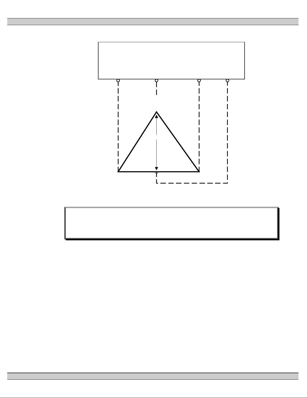
3.4. SYSTEM PHASING-HIGH LEG DELTA SYSTEMS
For systems using high leg delta 240V 3 phase 4 wire systems, connection of supply
conductors must have the correct phasing as shown below.
WARNING!
Failure to match correct system phasing
will result in serious damage to the
controller.
PM059 REV 6 08/05/05 3 Thomson Technology
Page 8
TS 830 TRANSFER SWITCH
Auto matic Transfer
Switch (Utility Supply)
PH A
(U A )
PH B
(U B )
PH C
(U C )
Neu ral
(N )
B
(O ra ng e)
(High Le g)
20 8V
C
(Ye llow )
A
(R ed )
24 0V 240V
12 0V 12 0V
N
(W hite )
CAUTION!!!
All installation and/or service work performed must be done by qualified
personnel only. Failure to do so may cause personal injury or death.
Where transfer switches are supplied without power isolation transformers (PT1 &
PT2) for ATS control logic it is essential that the orientation of phase conductors of
the supply source be arranged such that the phase of highest potential with respect
to ground is not connected to the power supply inputs to the controller (The A Phase
for both supplies). Failure to do so will result in equipment damage.
Per NEC Article 384-3 (f) “The B phase shall be that phase having the higher voltage
to ground on a 3-phase, 4-wire delta connected systems.”
3.5. REMOTE START CONTACT FIELD WIRING
For applications using TSC 80, 800 controllers, as a minimum, the remote engine
start control field wiring shall conform to the local regulatory authority on electrical
installations. Field wiring of a remote start contact from a transfer switch to a control
PM059 REV 6 08/05/05 4 Thomson Technology
Page 9

TS 830 TRANSFER SWITCH
panel should conform to the following guidelines to avoid possible controller
malfunction and/or damage.
3.5.1. Minimum #14 AWG (2.5mm2) wire size shall be used for distances up to 500ft
(150m)1). For distances exceeding 500 ft. (150m) consult Thomson
Technology.
3.5.2. Remote start contact wires should be run in a separate conduit.
3.5.3. Avoid wiring near AC power cables to prevent pick-up of induced voltages.
3.5.4. An interposing relay may be required if field-wiring distance is excessively
long (i.e. greater than 500 feet (150m) and/or if a remote contact has a
resistance of greater than 5.0 ohms.
3.5.5. The remote start contact must be voltage free (i.e. dry contact). The use of a
“powered” contact will damage the transfer controller.
3.6. DIELECTRIC TESTING
Do not perform any high voltage dielectric testing on the transfer switch with the
controller connected into the circuit, as serious damage will occur to the controller.
All AC control fuses and/or control circuit breakers or control circuit isolation plugs
connected to the controller must be removed if high voltage dielectric testing is
performed on the transfer switch.
3.7. INSTALLATION OF OPEN TYPE TRANSFER SWITCHES
Please contact Thomson Technology for additional information.
4. GENERAL DESCRIPTION
Thomson Technology TS 830 series of Automatic Transfer Switches employ two mechanically
interlocked enclosed contact power switching units and a microprocessor based controller to
automatically transfer system load to a generator supply in the event of a utility supply failure.
System load is then automatically re-transferred back to the utility supply following restoration of the
utility power source to within normal operating limits. Transfer switches with MEC 2, MEC 20 or
MEC 310 controllers installed have integral engine-genset auto start control & monitoring features
and therefore these applications do not require an engine-mounted auto start control panel.
The standard TS 830 series Automatic Transfer Switch is rated for 100% system load and does not
require upstream over current protection. Refer to Section 6 of this manual for detailed information
on over current protection.
PM059 REV 6 08/05/05 5 Thomson Technology
Page 10

TS 830 TRANSFER SWITCH
The TS 830 series transfer switch may be supplied with type TSC 80, TSC 800, MEC 310 or MEC
20 controllers as specified at equipment order. All controllers are microprocessor based which
provides all necessary control functions for fully automatic operation. The controllers are mounted
on the door of the transfer switch enclosure and operating status is shown via LED lights and/or
LCD display dependent upon controller type. For further information on the controller utilized, refer
to separate instruction manuals.
The power switching devices used for the Utility and Generator sources are operated by an
electrically driven motor mechanism in the transfer switch. The transfer switch motor utilizes the
power from the source to which the electrical load is being transferred. The mechanism provides a
positive mechanical interlock to prevent both power switching units from being closed at the same
time, which allows an interrupted “break-before-make” transfer sequence.
Note: For the purpose of this manual, the following standard nomenclature is utilized:
• Utility: to indicate the source of primary power
• Generator: to indicate the source of standby power
• Power switching device: to indicate the transfer switch power switching device
4.1. PRODUCT MODEL CODE
The type of TS 830 series transfer switch supplied is identified by way of a 21 digit product
code which appears on the equipment rating plate (MODEL) on the door of the transfer
switch, and on the transfer switch drawings. The model code structure and definitions are as
follows:
PM059 REV 6 08/05/05 6 Thomson Technology
Page 11

TS 830 TRANSFER SWITCH
ffff
G - 120240
(DELTA)
H - 220/380
2
ffff
S - 380
2
A - NEMA1, BEIGE
1
B - NEMA2, BEIGE
1
C - NEMA12, BEIGE
1
D - NEMA3R SD, BEIGE
1
E - NEMA3R DD, BEIGE
1
1
FOR PEAK PLUS ENCLOSURE COLOR
2
FOR 50 Hz APPLICATION
ffff
1 2 4 6 7 8 9 10 11 12 13 14 15 17 18 19 20 21
T S 8
1-3. SERIES
TS - TRANSFER SWITCH E - 120/208 U - INSULATED CASE DRAW-OUT SWITCH
4 & 5. MODEL
83 - 830 SWITCH
6. POLES M - 277/480 C/W ELECTRONIC & GF TRIP (800-3200A)
2 - 2 POLE
3 - 3 POLE P - 208
4 - 4 POLE Q - 220 19. GENERATOR SWITCHING DEVICE
7. CONFIGURATION TYPE
A - ATS U - 415 TRIP (100-800A)
X - SPECIAL P - MOLDED CASE SWITCH C/W ELECTRONIC
8 - 11. AMPERAGE 1 - TSC80 Q - INSULATED CASE, FIX MOUNT SWITCH
0100 2 - TSC800 (800A-3200A)
0250 4 - MEC2 (PCC) R - INSULATED CASE, FIX-MOUNT SWITCH
0400 5 - MEC20 (PCC) C/W ELECTRONIC TRIP (800-3200A)
0630 6 - PGC4000 U - INSULATED CASE DRAW-OUT SWITCH
0800 7 - NONE (MANUAL) (800 - 3200A)
1000 8 - MEC 310 (PCC) V - INSULATED CASE DRAW-OUT SWITCH
1200 9 - MEC 320 C/W ELECTRONIC TRIP (800 - 4000A)
1600 W - INSULATED CASE, DRAW-OUT SWITCH
2000 17. ENCLOSURE TYPE C/W ELECTRONIC & GF TRIP (800-3200A)
2500
3200
12. APPLICATION
A - STANDARD ATS
C - DUAL SOURCE F - NEMA4X DD, STAINLESS STEEL
P - POWER CONTROL CENTRE (PCC) G - NONE (OPEN STYLE) 21. ATS CONNECTION CONFIGURATION
S - PEAK PLUS X - SPECIAL A - STANDARD
X - SPECIAL B - ALTERNATE B (1000-1600A)
13. OPERATION TYPE K - MOLDED CASE SWITCH (100 - 1200 A) D - ALTERNATE D (1000-1600A)
1 - OPEN TRANSITION M - MOLDED CASE SWITCH C/W THER-MAG E - ALTERNATE E (800-3200A)
2 - MANUAL ELEC. OP. TRIP (100-800A) F - ALTERNATE F (800-3200A)
4 - CLOSED TRANSITION (SOFT LOAD) N - MOLDED CASE SWITCH C/W ELECTRONIC G - ALTERNATE G (800-3200A)
X - SPECIAL TRIP (250-1200A) X - SPECIAL
14 . SAFETY STANDARD & GF TRIP (250-1200A) NOTES
X - NOT APPLICABLE Q - INSULATED CASE, FIX MOUNT SWITCH
15 . VOLTAGE R - INSULATED CASE, FIX-MOUNT SWITCH
1
3 WIRE
D - 120/240
5 16
3
3
4 WIRE (GROUNDED NEUTRAL)
F - 127/220 (800 - 3200A)
J - 240/415 W - INSULATED CASE, DRAW-OUT SWITCH
3
3 WIRE
R - 240 K - MOLDED CASE SWITCH (100 - 1200 A)
V - 480 N - MOLDED CASE SWITCH C/W ELECTRONIC
X - SPECIAL TRIP (250-1200A)
16. CONTROLLER
18. UTILITY SWITCHING DEVICE
P - MOLDED CASE SWITCH C/W ELECTRONIC
(800A-3200A) IS ASA #61 GREY
C/W ELECTRONIC TRIP (800-3200A)
18. UTILITY SWITCHING DEVICE CONTINUED
V - INSULATED CASE DRAW-OUT SWITCH
C/W ELECTRONIC TRIP (800 - 4000A)
X - SPECIAL
M - MOLDED CASE SWITCH C/W THER-MAG
& GF TRIP (250-1200A)
X - SPECIAL
20. POWER CONNECTIONS
A - STANDARD
X - SPECIAL
C - ALTERNATE C (1000-1600A)
PM059 REV 6 08/05/05 7 Thomson Technology
Page 12

TS 830 TRANSFER SWITCH
5. GENERAL THEORY OF OPERATION
5.1. STANDARD AUTOMATIC TRANSFER SWITCH
5.1.1. NORMAL OPERATION
When utility supply voltage drops below a preset nominal value (adjustable from 70%
to 100% of nominal) on any phase, an engine start delay circuit will be initiated and
the transfer to utility supply signal will be removed (i.e. contact opening). Following
expiry of the engine start delay period (adjustable from 0 to 60 sec.) an engine start
signal (contact closure) will be given.
Once the engine starts, the transfer switch controller will monitor the generator
voltage and frequency levels. Once the generator voltage and frequency rises above
preset values (adjustable from 70% to 95% of nominal), the engine warmup timer will
be initiated. Once the warmup timer expires (adjustable from 0 to 60 sec.), the
Transfer to Generator Supply signal (contact closure) will be given to the transfer
switch mechanism. The load will then transfer from the utility supply to the generator
supply via the motor driven mechanism.
The generator will continue to supply the load until the utility supply has returned.
The retransfer sequence is completed as follows: when the utility supply voltage is
restored to above the preset values (adjustable from 70% to 95% of nominal) on all
phases, a transfer return delay circuit will be initiated. Following expiry of the Utility
Return Timer (adjustable from 0 to 30 min.), the Transfer to Generator Supply signal
will be removed (contact opening), and then the Transfer to Utility Supply signal
(contact closure) will be given to the transfer switch mechanism. The load will then
retransfer the load from the generator supply back to the utility supply. Note: For
transfer switches with TSC 80/800 controllers, a neutral delay timer circuit will delay
the transfer sequence in the neutral position (i.e. both power switching devices open)
until the neutral time delay period expires (adjustable from 0 to 60 sec.).
An engine cooldown timer circuit will be initiated once the load is transferred from the
generator supply. Following expiry of the cooldown delay period (adjustable from 0
to 30 min.), the engine start signal will be removed (contact opening) to initiate
stopping of the generator set. Note: For transfer switches with MEC 2/20, MEC 310
controllers, engine start signal is internal to the controller.
PM059 REV 6 08/05/05 8 Thomson Technology
Page 13

TS 830 TRANSFER SWITCH
5.1.2. OVER CURRENT TRIP (TSC 80/TSC 800 CONTROLLERS)
Should the utility power switching device trip open due to an over current condition,
TSC 80 or TSC 800 transfer controller will initiate an engine start signal and will
permit transfer of the load to the generator supply. The utility source will be locked
out and the load will remain on the generator supply until the TSC 80/TSC 800 alarm
signal is manually reset.
Refer to the TSC 80 & TSC 800 Instruction Manuals for further details on Transfer
Fail operation.
Should the generator power switching device trip open due to an over current
condition, TSC 80/TSC 800 transfer controller will initiate transfer of the load to the
utility supply. The generator source will be locked out and the load will remain on the
utility supply until the TSC 80/TSC 800 alarm signal is manually reset.
5.1.3. OVER CURRENT TRIP (MEC 2/MEC 20/MEC 310 CONTROLLERS)
Should the utility power switching device trip open due to an overcurrent condition,
the generator will not automatically start and transfer on load. The generator must be
started and transferred on load manually.
Should the generator power switching device trip open due to an overcurrent
condition, the generator will shutdown and the load will automatically return to the
utility supply if its voltage is normal. Note: for automatic transfer to utility, the transfer
switch must be factory ordered with a “gen breaker tripped” auxiliary contact inside
the generator power switching device and must be wired to the gen set controllers
shutdown alarm circuits.
Refer to the Gen Set controller instruction manual for further details on manual
operation or shutdown-reset operation.
5.2. TEST MODES
The transfer switch may be tested utilizing the controller pushbuttons or optional test switch.
A simulated utility power failure condition will be activated when the test mode is selected.
The transfer switch will operate as per a normal utility power fail condition.
The transfer switch will remain on generator supply until the test mode is terminated. It will
then immediately transfer back to the utility supply and then continue to operate the
PM059 REV 6 08/05/05 9 Thomson Technology
Page 14

TS 830 TRANSFER SWITCH
generator set for its cooldown period then stop. Note: The transfer switch will automatically
return to the utility supply (if within nominal limits) if the generator set fails while in the test
mode.
6. OVER CURRENT PROTECTION
Thomson Technology TS 830 series of Automatic Transfer Switches are supplied standard with
integral over current protection.
The type of over current protection utilized is dependent upon ATS amperage size and optional
features specified. For transfer switches rated 100A through 800A, over current protection is non-
adjustable thermal-magnetic type trip units. For transfer switches rated 1000A through 1600A over
current protection is adjustable electronic type with long time & instantaneous trip unit elements with
optional ground fault protection elements.
Note: For models of transfer switch with adjustable integral over current protection trip units, the
over current protection must be set prior to operation. The equipment will be shipped from the
factory with a long-time current setting of 100% (of the equipment rating) and maximum
instantaneous/short-time/ground fault (if supplied) current and time delay settings.
WARNING!
Do Not Energize this equipment until
device settings have been verified to
ensure proper system protection &
coordination. Failure to do so may result
in equipment failure.
7. GENERAL NOTES ON SERVICING ATS MECHANISM
(See CAUTION! on Page #2)
When performing any service work on the transfer mechanism, it is imperative that the following be
observed:
7.1. To maintain mechanical integrity, ensure that:
• All limit switches linkages are correctly adjusted to provide full travel of the power
switching device toggles without exerting unnecessary forces associated with
excessive travel. Ensure that power switching device travel far enough to reset
any internal trip unit (it is more important for the toggle to go fully in the "off"
direction, than in the "on" direction).
PM059 REV 6 08/05/05 10 Thomson Technology
Page 15

TS 830 TRANSFER SWITCH
• Mechanical interlocking is correct when one power switching opens well before
the other should close.
• All fasteners are adequately tightened.
• The operating linkages are not damaged or bent, and that all bearing points
operate freely.
7.2. To maintain electrical integrity, ensure that:
• All electrical connections, especially power connections, are clean and
adequately tightened. Corroded or loose power connections will cause
destructive heating, and may cause premature tripping.
• All insulating devices are in place and in good condition.
• No moisture or other contamination is present.
• Electrical conductors are adequately secured away from moving parts.
• On HS style transfer switch mechanisms, check nylock nuts on bolt pivot points.
Operation arms should move freely without excessive play.
7.3. To maintain operational integrity, ensure that:
• All control devices are in good condition and correctly calibrated.
• All control devices are adequately secured in their plug-in fixtures.
Only qualified personnel should undertake service work. Failure to correctly maintain an
automatic transfer switch may present a hazard to life and equipment. Full operational
testing must be done prior to placing a transfer switch in service subsequent to any
maintenance or repair. Any service work involving electrical components requires high-
potential testing to ensure that required insulation levels have been maintained.
8. TRANSFER SWITCH MECHANISM – 100 - 800 Amp (HS Style)
Note: Refer to product drawings in sections 11-14for identification of Transfer Switch Mechanism
style supplied with the Transfer Switch.
The transfer mechanism consists primarily of the transfer gear motor, a drive hub assembly, and
two power switching device operating arms.
The reversible transfer gear motor drives the drive hub assembly, which in turn moves the power
switching device operating arms. The power switching device toggles are set inside the operating
arm slots and are moved by them. There are two limit switches, which are contacted by the
operating arms (one for each direction of travel), which disconnect the transfer motor power supply
when the power switching devices have attained full travel. Should limit switch adjustment be
required, it is advisable to consult Thomson Technology for further information.
The transfer switch mechanism has three possible positions:
a) Utility power switching device closed and generator power switching device open;
PM059 REV 6 08/05/05 11 Thomson Technology
Page 16

TS 830 TRANSFER SWITCH
b) Generator power switching device closed and utility power switching device open;
c) Both utility and generator power switching devices open, but NEVER both utility and
generator power switching devices closed at the same time.
8.1. MANUAL OPERATION
DANGER!!!!
Arc Flash and Shock Hazard. Will cause severe injury or death.
Do not open equipment until ALL power sources are disconnected
This equipment must be installed and serviced only by qualified electrical
personnel utilizing safe work practices and appropriate Personal Protective
Equipment (PPE). Failure to do so may cause personal injury or death
Isolate the transfer switch from all sources of supply before opening the enclosure for
manual operation. With all sources of power de-energized to the transfer switch, the control
circuit isolation plug can be unplugged to prevent subsequent operation. The control circuit
isolation plug is located on the inner side of the transfer switch enclosure door.
To operate manually, turn the operating handle on the front of the mechanism and rotate to
the desired position.
Automatic operation may be regained by replacing the control circuit isolation plug. With all
sources of power de-energized to the transfer switch, the control circuit isolation plug can be
re-connected. The drive system will operate the transfer switch to the required position.
9. TRANSFER SWITCH MECHANISM – 1000A- 1600 Amp (T Style)
The transfer mechanism consists primarily of the transfer motor, a hub assembly, two operating
rods and two power switching device operating yokes.
The reversible transfer motor drives the hub assembly, which in turn moves the operating rods that
are connected to the power switching device operating yokes. The power switching device toggles
are set inside the yokes and are moved by them. There are two limit switches, which are contacted
by the operating yokes (one for each direction of travel), which disconnect the transfer motor power
supply when the power switching devices have attained full travel. The adjuster screws located on
PM059 REV 6 08/05/05 12 Thomson Technology
Page 17

TS 830 TRANSFER SWITCH
the yoke determines the operating point of these limit switches. Should adjustment be required, it is
advisable to consult Thomson Technology for further information.
The transfer switch mechanism has three possible positions:
a) Utility power switching device closed and generator power switching device open;
b) Generator power switching device closed and utility power switching device open;
d) Both utility and generator power switching devices open, but NEVER both utility and
generator power switching devices closed at the same time.
9.1. MANUAL OPERATION
(See CAUTION! on Page #2)
Isolate the transfer switch from all sources of supply before opening the enclosure for
manual operation. With all sources of power de-energized to the transfer switch, the control
circuit isolation plug (PL12) can be unplugged to prevent subsequent operation.
To operate manually, pull the release plunger and operate the handle in the desired
direction.
Automatic operation may be regained by replacing the isolation plug. With all sources of
power de-energized to the transfer switch, the control circuit isolation plug (PL12) can be re-
connected. The drive system is self-engaging and will operate the transfer switch to the
required position. (See manual operation instruction on front of transfer switch mechanism.)
PM059 REV 6 08/05/05 13 Thomson Technology
Page 18

TS 830 TRANSFER SWITCH
10. RECOMMENDED MAINTENANCE
(See CAUTION! on Page #2)
10.1. DO NOT perform dielectric tests on the equipment with the control components in the
circuit.
10.2. Check if control components are tight in sockets.
10.3. Periodically inspect all terminals (load, line and control) for tightness. Re-torque all
bolts, nuts and other hardware. Clean or replace any contact surfaces that are dirty,
corroded or pitted.
10.4. Transfer switches should be in a clean, dry and moderately warm location. If signs of
moisture are present, dry and clean transfer switch. If there is corrosion, try to clean
it off. If cleaning is unsuitable, replace the corroded parts. Should dust and/or debris
gather on the transfer switch, brush, vacuum, or wipe clean. DO NOT blow dirt into
power switching devices.
10.5. Test the transfer switch operation. While the unit is exercising, check for freedom of
movement, hidden dirt, corrosion or any excessive wear on the mechanical operating
parts. Ensure that the power switching device travel is correct.
10.6. Verify all program settings on the controller as per the calibration label or
programming sheets.
10.7. Transfer Mechanism 100-800A HS Style –lubrication of drive hub/operator arm
interface. Use high viscosity moly lubricant
10.8. Transfer Mechanism 1000A-1600A (T Style) - ensure that the manual handle moves
freely on the hub when the lock pin is disengaged. If lubrication is necessary, apply
medium weight (SAE 20) oil sparingly.
10.9. Transfer Mechanism 1000A-1600A (T-Style) - yoke pivot bearings and rod ends are
permanently lubricated and do not require maintenance.
10.10. The motor and gearbox are permanently lubricated, and should not require attention
under normal operating circumstances.
PM059 REV 6 08/05/05 14 Thomson Technology
Page 19

TS 830 TRANSFER SWITCH
11. FRONT VIEW (TYPICAL) 3 / 4 POLE 100A-400A TRANSFER
MECHANISM (HS Style)
PM059 REV 6 08/05/05 15 Thomson Technology
Page 20

TS 830 TRANSFER SWITCH
12. FRONT VIEW (TYPICAL) 3 / 4 POLE 100A-400A TRANSFER
MECHANISM (HS Style) (Front Cover Removed)
PM059 REV 6 08/05/05 16 Thomson Technology
Page 21

TS 830 TRANSFER SWITCH
13. FRONT VIEW (TYPICAL) 3 / 4 POLE 630A-800A TRANSFER
MECHANISM (HS Style)
PM059 REV 6 08/05/05 17 Thomson Technology
Page 22

TS 830 TRANSFER SWITCH
14. FRONT VIEW (TYPICAL) 3 / 4 POLE 630A-800A TRANSFER
MECHANISM (HS Style) (Front Cover Removed)
PM059 REV 6 08/05/05 18 Thomson Technology
Page 23

TS 830 TRANSFER SWITCH
15. FRONT VIEW (TYPICAL) 3 / 4 POLE 600A-1600A TRANSFER
MECHANISM
PM059 REV 6 08/05/05 19 Thomson Technology
Page 24

TS 830 TRANSFER SWITCH
16. CABLE TERMINAL INFORMATION
CONNECTION TIGHTNESS
TERMINAL RATING
BASIC MODEL
QTY
PER
PHASE
RANGE
TERMINAL
MOUNTING
SCREW
TS 83xA-0100 1 #2–4/0
TS 83xA-0250 1 #6–350MCM 150 275
TS 83xA-04001 2 2/0–500MCM 72 275
TS 83xA-06301 2 2/0–500MCM 72 275
TS 83xA-08001 3 2/0–500MCM 110 375
TS 83xA-10001 4 4/0–500MCM 375 375
TS 83xA-12001 4 4/0–500MCM 375 375
TS 83xA-16001 4 #2–600MCM 375 375
1. Optional terminal ratings are available in some models – Consult Thomson Technology.
2. For other model types not shown, contact Thomson Technology for further information.
(In-lbs)
CABLE
CLAMP
120 50
17. ELECTRICAL RATINGS
100A
MODEL TYPE
Rated short circuit breaking
capacity (Icu) kA @400V
Withstand rating fuse
protected (kA)
Rated service short circuit
breaking capacity (Ics) kA
@400V
Mechanical endurance
(Number of Operations)
(HS
Style)
50 65 65 80 65 50 50
100 100 100 100 100 100 100
42 48 48 60 48 50 50
7000 6000 4000 4000 4000 2500 2500
250A
(HS
style)
400A
(HS
Style)
630A (HS Style) 800A
(HS Style)
1000/1200A
(T Style)
1600A
(T
Style)
PM059 REV 6 08/05/05 20 Thomson Technology
Page 25

TS 830 TRANSFER SWITCH
18. TROUBLESHOOTING
CAUTION!!!
All trouble shooting/ service work performed must be done by qualified
personnel only. Failure to do so may cause personal injury or death.
Note: An optional hand held, plug-in Service Display Module (SDM) is available for the TSC 80
Transfer Controller. The SDM module provides an LCD screen to display additional detailed
information on the operation and settings of the TSC 80 controller for simplified servicing/trouble
shooting procedures. For detailed information, refer to the separate SDM module instruction manual
(PM065).
Symptom
Will not re-transfer to utility source
upon restoration
Will not transfer to generator source
upon failure of utility source
Possible Causes
- Isolation plug out
- A test mode has been activated (check controller)
- Utility voltage is below the pre-programmed limits (check utility
source for adequate voltage)
- A loose control connection
- Faulty motor limit switch
- Defective motor
- Controller has incorrect voltage programming jumper setting for
correct system voltage
- Defective controller (verify output signals with circuit board
mounted diagnostic LED’s)
- TSC 80/800 Controller has “Transfer Fail” alarm activated as
indicated by flashing Load on Utility LED. Determine cause of
alarm and rectify before TSC is reset
- Isolation plug out
- Generator set not producing enough voltage/frequency or
output circuit breaker open
- Controller has incorrect voltage programming jumper setting for
correct system voltage
- Warm-up time delay function has not timed out yet (verify
controller timer setting)
- A loose control connection
Transfer to generator source without a
power failure in the utility source
PM059 REV 6 08/05/05 21 Thomson Technology
- Faulty motor limit switch
- Defective motor
- Defective controller (verify output signals with circuit board
mounted diagnostic LED’s)
TSC 80/800 Controller has “Transfer Fail” alarm activated as
indicated by flashing Load on Generator LED. Determine
cause of alarm and rectify before TSC 80 is reset
-
A test mode has been activated Utility supply voltage is slightly
-
below voltage sensing setpoints.
Page 26

Symptom
TS 830 TRANSFER SWITCH
Possible Causes
Will not re-transfer to utility source
upon restoration
Generator does not start up or stop
when it should
No time delay when there should be
Power is not available at the load
terminals but the utility or generator
power switching device appears to be
closed to a live source
- Limit switch incorrectly adjusted
- Isolation plug out
Verify controller has correct voltage programming jumper
setting for system voltage
- Defective controller (verify output signals with circuit board
mounted diagnostic LED’s)
- TSC 80/800-Utility power switching device has tripped due to
an over current condition and controller alarm activated as
indicated by flashing Load on Utility LED. Determine cause of
alarm and rectify before controller is reset.
- Verify remote engine control panel is set for automatic mode
- Verify time delay setting of the controller
- The power switching device's over current protection unit has
opened due to a fault on the system. ”. Correct the fault, and
manually reset the power switching device in the transfer
switch by moving it off and then on again with the manual
operating handle
-
The transfer switch has completed a
transfer, but the motor has overheated
and the internal thermal protector has
opened
Limit switch failure or improper adjustment has failed to
disconnect motor
Binding or jamming of the transfer mechanism
-
19. REPLACEMENT PARTS
Replacement parts are available for the transfer switch as follows:
Note
When ordering replacement parts please provide the
following information:
-Transfer Switch Model code (e.g. TS 873AA0200AS)
-Transfer Switch Serial Number (e.g. W-022345)
The above information can be found on the transfer
switch equipment rating plate located on the outside of
the ATS door.
PM059 REV 6 08/05/05 22 Thomson Technology
Page 27

TS 830 TRANSFER SWITCH
Component Description
MEC 310 Controller MEC310AXX1 Must configure program settings to
TSC 80 Controller Board 005712 Must set Program Jumper prior to
TSC 80 Lexan Faceplate 005336 Contact Thomson Technology
TSC 80 Rear Cover 005707
Thomson Technology
Part Number
Comments
match original controller settings
use. Refer to TSC 80 Instruction
Manual.
Service Dept for installation
procedures.
Limit Switch 1 n/o, 1 n/c (all
ATS Models)
Transfer Switch Motor (T Style
(1000A-1200A) 120V 1/10 hp 1
PH
120VAC Auxiliary Plug-in
Relay, 11 pin Square (UX/GX)
120VAC Auxiliary Plug-in Timer 001515 Must ensure coil voltage is correct
100VA Control Transformer 002159
For other parts not listed, please contact Thomson Technology.
004929 Must install and adjust for proper
operation before use. Contact
Thomson Technology Service Dept
for installation/adjustment
procedures
001075 Motor is supplied with gear box
assembly. Contact Thomson
Technology Service Dept for
installation procedures
001278 Must ensure coil voltage is correct
20. PRODUCT RETURN POLICY
Thomson Technology uses a Return Material Authorization (RMA) process. Please complete the
Return Authorization Request Form (available on our web page) for return of goods, warranty
replacement/repair of defective parts, or credit consideration and fax to the appropriate department.
Returns only: Sales Fax (604) 888-5606
Warranty replacement/Warranty Repair: Service Fax (604) 888-3370.
Upon receipt of your request, Thomson Technology will confirm with a copy of our Order
Acknowledgement via fax advising the RMA number which should be used to tag the defective
controller prior to shipment.
PM059 REV 6 08/05/05 23 Thomson Technology
Page 28

TS 830 TRANSFER SWITCH
21. NOTES
________________________________________________________________________
________________________________________________________________________
________________________________________________________________________
________________________________________________________________________
________________________________________________________________________
________________________________________________________________________
________________________________________________________________________
________________________________________________________________________
________________________________________________________________________
________________________________________________________________________
________________________________________________________________________
________________________________________________________________________
________________________________________________________________________
________________________________________________________________________
________________________________________________________________________
________________________________________________________________________
________________________________________________________________________
________________________________________________________________________
________________________________________________________________________
________________________________________________________________________
________________________________________________________________________
________________________________________________________________________
________________________________________________________________________
________________________________________________________________________
________________________________________________________________________
________________________________________________________________________
________________________________________________________________________
________________________________________________________________________
________________________________________________________________________
________________________________________________________________________
_______________________________________________________________________
PM059 REV 6 08/05/05 24 Thomson Technology
 Loading...