

Page 1

Power
E
th
ern
et
W
LA
N
Plug-in
ISDN
Internet
DSL
TR-069 Configuration Guide
R7.4 and higher
Thomson Gateway
Page 2

Page 3

Thomson Gateway
TR-069 Configuration Guide
R7.4 and higher
Page 4

Copyright
Copyright ©1999-2008 Thomson. All rights reserved.
Distribution and copying of this document, use and communication of its contents is not permitted without written authorization
from Thomson. The content of this document is furnished for informational use only, may be subject to change without notice,
and should not be construed as a commitment by Thomson. Thomson assumes no responsibility or liability for any errors or
inaccuracies that may appear in this document.
Thomson Telecom Belgium
Prins Boudewijnlaan, 47
B-2650 Edegem
Belgium
http://www.thomson-broadband.com
Trademarks
The following trademarks may be used in this document:
DECT is a trademark of ETSI.
Bluetooth® word mark and logos are owned by the Bluetooth SIG, Inc.
Ethernet™ is a trademark of Xerox Corporation.
Wi-Fi®, WMM® and the Wi-Fi logo are registered trademarks of the Wi-Fi Alliance®. "Wi-Fi CERTIFIED", "Wi-Fi ZONE",
"Wi-Fi Protected Access", "Wi-Fi Multimedia", "Wi-Fi Protected Setup", WPA", WPA2" and their respective logos are trademarks of the Wi-Fi Alliance®.
UPnP™ is a certification mark of the UPnP™ Implementers Corporation.
Microsoft®, MS-DOS®, Windows®, Windows NT® and Windows Vista® are either registered trademarks or trademarks
of Microsoft Corporation in the United States and/or other countries.
Apple® and Mac OS® are registered trademarks of Apple Computer, Incorporated, registered in the United States and
other countries.
UNIX® is a registered trademark of UNIX System Laboratories, Incorporated.
Adobe®, the Adobe logo, Acrobat and Acrobat Reader are trademarks or registered trademarks of Adobe Systems, Incor-
porated, registered in the United States and/or other countries.
Other brands and product names may be trademarks or registered trademarks of their respective holders.
Document Information
Status: v1.0 (May 2008)
Reference: E-DOC-CTC-20071119-0003
Short Title: Config Guide: TR-069 R7.4 and higher
Page 5

E-DOC-CTC-20071119-0003 v1.0
i
Contents
About this TR-069 Configuration Guide ................................... 1
1 Introduction.................................................................................. 3
1.1 References and Related Documents ............................................................... 4
1.2 CWMP Transaction Sessions ........................................................................... 6
1.3 IGD Data model on the Thomson Gateway ................................................... 10
2 Configuring CWMP on the Thomson Gateway ...................... 13
2.1 Configuring TLS ............................................................................................ 14
2.1.1 TLS Client .............................................................................................................................................. 15
2.1.2 TLS Certificates .....................................................................................................................................16
2.2 Configuring CWMP........................................................................................ 18
2.2.1 CWMP Service Manager ......................................................................................................................19
2.2.2 CWMP Daemon as seen from the ACS............................................................................................... 21
2.2.3 CWMP Daemon towards the ACS.......................................................................................................24
2.2.4 Notification Rules .................................................................................................................................25
2.2.5 Runtime Variables ................................................................................................................................26
2.3 Configuring State Checks ............................................................................. 28
3 Firmware Upgrade and Configuration Update ....................... 31
3.1 Firmware Upgrade......................................................................................... 32
3.1.1 General Firmware Upgrade Mechanism ............................................................................................33
3.1.2 Single Memory Bank Firmware Upgrade...........................................................................................35
3.1.3 Dual Memory Bank Firmware Upgrade ..............................................................................................37
3.1.4 Firmware Upgrade with Reduced Memory Mode .............................................................................39
3.2 Configuration Update ................................................................................... 41
3.2.1 Configuration Update Mechanism......................................................................................................42
3.2.2 STS Files................................................................................................................................................44
3.2.3 Embedded STS (eSTS) Files................................................................................................................ 46
4 Monitoring and Diagnostics ..................................................... 47
4.1 View on Home Network ................................................................................ 48
4.2 Diagnostics ................................................................................................... 50
4.3 IP Ping Diagnostics Test ............................................................................... 54
Page 6

E-DOC-CTC-20071119-0003 v1.0
ii
Contents
4.4 Retrieval of the Device Log ........................................................................... 56
4.5 Event Subscription ........................................................................................ 57
5 WAN Connections .....................................................................59
5.1 WAN Connection Device ............................................................................... 61
5.2 WAN PPP or IP Connection ........................................................................... 62
5.3 Connection Information ................................................................................ 65
5.4 Forwarding Entries........................................................................................ 66
6 Service Provisioning.................................................................. 69
6.1 VoIP ............................................................................................................... 70
6.2 WLAN ............................................................................................................ 73
6.3 Time .............................................................................................................. 76
6.4 DHCP Conditional Serving ............................................................................ 77
6.5 Queue Management ...................................................................................... 79
6.6 Stateful Inspection Firewall .......................................................................... 81
6.7 Access Rights................................................................................................ 85
6.8 NAT Application List ..................................................................................... 87
6.9 Dynamic DNS ................................................................................................ 90
6.10 Remote Access (Remote Assistance) ............................................................ 93
6.11 Parental Control ............................................................................................ 95
6.12 VLAN Provisioning (Layer2Bridging) ............................................................. 97
7 Zero-Provisioning ....................................................................101
Page 7

E-DOC-CTC-20071119-0003 v1.0
1
About this TR-069 Configuration Guide
About this TR-069 Configuration Guide
Used Symbols
Terminology
Generally, the Thomson Gateway123 will be referred to as Wireless USB Adaptor in this TR-069 Configuration
Guide.
Typographical Conventions
Following typographical convention is used throughout this manual:
Sample text indicates a hyperlink to a Web site.
Example: For more information, visit us at www.thomson-broadband.com
.
Sample text indicates an internal cross-reference.
Example: If you want to know more about guide, see “1 Introduction” on page 7”.
Sample text indicates an important content-related word.
Example: To enter the network, you must authenticate yourself.
Sample text indicates a GUI element (commands on menus and buttons, dialog box elements, file
names, paths and folders).
Example: On the File menu, click Open to open a file.
Documentation and software updates
Thomson continuously develops new solutions, but is also committed to improving its existing products.
For more information on Thomson's latest technological innovations, documents and software releases, visit
us at http://www.thomson-broadband.com
.
A note provides additional information about a topic.
A caution warns you about potential problems or specific precautions that need to be taken.
Page 8

E-DOC-CTC-20071119-0003 v1.0
2
About this TR-069 C
onfiguration Guide
Overview
This TR-069 Configuration Guide provides technical information on TR-069 and how this relates to the
various Thomson Gateway products. In the first chapter, a brief introduction to the TR-069 CWMP protocol
and the TR-098 IGD data model is presented. The following chapter gives detailed information on the
configuration of CWMP on the Thomson Gateway using CLI commands. The last chapters focus on the
different use cases that are currently supported using CWMP.
This document is structured as follows:
Topi c Page
“1 Introduction” 3
“2 Configuring CWMP on the Thomson Gateway” 13
“3 Firmware Upgrade and Configuration Update” 31
“4 Monitoring and Diagnostics” 47
“5 WAN Connections” 59
“6 Service Provisioning” 69
“7 Zero-Provisioning” 101
Page 9

E-DOC-CTC-20071119-0003 v1.0
3
1| Introduction
1 Introduction
Introduction
This chapter provides a short introduction to the TR-069 CWMP protocol and the TR-098 IGD data model.
Overview
This chapter is structured as follows:
Topi c Page
“1.1 References and Related Documents” 4
“1.2 CWMP Transaction Sessions” 6
“1.3 IGD Data model on the Thomson Gateway” 10
Page 10

E-DOC-CTC-20071119-0003 v1.0
4
1| Introduction
1.1 References and Related Documents
TR-069: CPE WAN Management Protocol (CWMP)
TR-069 specifies the CWMP protocol, which is used for remote management of CPE devices. The Thomson
Gateway supports CWMP. This allows the Thomson Gateway to be configured and monitored from a
management application running on a remote Auto-Configuration Server (ACS).
For more information on CWMP, see:
Technical Report “TR-069 - CPE WAN Management Protocol”, DSL Forum, May 2004.
Technical Report “TR-069 Amendment 1 - CPE WAN Management Protocol”, DSL Forum, November
2006.
TR-098: Internet Gateway Device (IGD) Data Model
TR-098 specifies the InternetGatewayDevice data model for TR-069 enabled devices. The Thomson Gateway
supports the IGD data model. This data model is a set of parameters, modelled in a tree structure, that can be
managed using CWMP.
For more information on the IGD data model, see:
Technical Report “TR-098 - Internet Gateway Device Version 1.1 Data Model for TR-069”, DSL Forum,
September 2005.
Technical Report “TR-098 Amendment 1 - Internet Gateway Device data model for TR-069”, DSL Forum,
November 2006.
Related documents
Several DSL-Forum documents are related to TR-069 and TR-098, specifying data models for devices other
than an IGD (for example STB, PCs, NAS), or specifying extensions of the IGD data model.
Following specifications are relevant to this configuration guide:
TR-064 “LAN-side DSL CPE configuration”, May 2004: this document provides a standard interface for
PC-based (LAN-side) install applications. It defines LAN-side CPE configuration.
TR-104 “Provisioning parameters for VoIP CPE”, September 2005: this document defines a generic
VoiceService data model for provisioning of VoIP CPEs, for example an Integrated Access Device (IAD) or
an Analogue Telephone Adapter (ATA). The model supports SIP, MGCP and H323 signalling protocols.
TR-106 Amendment 1 “Data model template for TR-069 enabled devices”, November 2006: this
document defines a Device data model for any TR-069 enabled LAN device that is not an IGD. This model
supports the DeviceSummary parameter.
TR-111 “Applying TR-069 to remote management of home networking devices”, December 2005: this
document defines two mechanisms that extend TR-069 with remote management of LAN devices behind
an Internet Gateway.
LAN Device-gateway association: this mechanism allows an ACS managing a LAN device to identify
the associated gateway through which that device is connected. The gateway and LAN device
exchange their device identity (OUI-product class-serial number) via DHCP option 125.
Connection Request via NAT gateway: this mechanism allows an ACS to initiate a TR-069 session
with a LAN device that is operating behind a NAT gateway. STUN (Simple Traversal of UDP through
NAT) is used between the LAN device and the ACS.
In addition, extensions to the Device and InternetGatewayDevice data models are defined.
WT-107 “Internet Gateway Device data model (TR-098 issue 2)”, September 2006: this document extends
the IGD data model with DHCP conditional serving, HPNAv3, MoCA, 802.1X,...
WT-135 “Data model for TR-069 enabled STB”: this document defines a STBDevice data model for a STB
(Set-Top Box) CPE as an extension of TR-069.
Page 11

E-DOC-CTC-20071119-0003 v1.0
5
1| Introduction
WT-140 “TR-069 data model for storage service enabled devices”: this document defines a
StorageService data model for a device that maintains a storage service, such as a Network Attached
Storage (NAS) device, as an extension of TR-069.
PD-128 version 6 “Interoperability test plan for TR-069 plugfests”, June 2006: this document defines
TR-069 tests and their expected outcome. These tests are used during the TR-069 plugfests as tests to
perform. The DSL Forum regularly organizes TR-069 plugfest test events where all participating CPE
devices can test against all participating ACS servers. The document is also the de facto reference for
TR-069 testing by customers and ACS vendors.
Architecture
Following illustration shows the location of the specifications in the CWMP architecture:
Thomson firmware is interoperability tested with and by ACS partners.
ACS
DSLAM BRAS ACS
Access
Network
CPE
IP
Network
TR-069 CWMP (Am.1)
Provid
er
Helpde
sk
CPE
CPE
CPE
TR-064
LAN CPE Auto-Configuration
WT-135
S
TB Model
TR-104
VoIP Model
TR-098 (Am.1)
IGD Model
TR-111 CWMP
for home devices
TR-106 CWMP enabled
device model template
WT-140
Network Storage Model
Page 12

E-DOC-CTC-20071119-0003 v1.0
6
1| Introduction
1.2 CWMP Transaction Sessions
What is a transaction session?
TR-069 defines a transaction session as a sequence of Remote Procedure Calls (RPCs), both requests and
responses. A transaction session is completed when both parties (CPE and ACS) have no messages left to
send.
The CPE has an important role:
All transaction sessions are established by the CPE.
The CPE maintains a TCP connection (persistent HTTP connection) for the duration of the session.
The CPE is also responsible for closing a transaction session.
Session establishment
All transaction sessions are established by the CPE, by sending an Inform RPC to the ACS.
We distinguish two types of transaction sessions:
CPE initiated sessions
Asynchronous ACS initiated sessions: the CPE establishes a transaction session to the ACS after receipt
of a Connection Request from the ACS.
Page 13

E-DOC-CTC-20071119-0003 v1.0
7
1| Introduction
Inform events
The Inform RPC contains the Inform event argument, to indicate the cause(s) of the transaction session
establishment.
Following table gives an overview of the different Inform events and their use:
Initial handshake
The initial handshake between the CPE and the ACS takes place when the CPE contacts the ACS for the very
first time or due to a change of the ACS URL.
Following actions are taken during the initial handshake:
The CPE sends an initial Inform RPC with the “0 BOOTSTRAP” event.
The CPE authenticates itself to the ACS.
The ACS requests the list of methods that are supported by the CPE using the GetRPCMethods RPC.
The ACS activates the required services on the CPE, according to the “activation policies”. For example,
the ACS configures the voice service and wireless service.
Forced reboot
The Reboot RPC causes the CPE to reboot. This forced reboot might be desired to restart the Thomson
Gateway clearing all state.
Event Description
0 BOOTSTRAP The first time that the CPE contacts the ACS.
1BOOT After a power up or reset of the CPE.
2 PERIODIC The session is established on a periodic Inform interval.
3 SCHEDULED Scheduled by a ScheduleInform RPC.
4 VALUE CHANGE The value of a parameter of the Inform ParameterList argument
changed. This can be a parameter that is marked by the ACS for
notification (either active or passive) or a change of one of following
parameters:
InternetGatewayDevice.DeviceInfo.SoftwareVersion
InternetGatewayDevice.DeviceInfo.ProvisioningCode
InternetGatewayDevice.ManagementServer.ConnectionRequestURL
InternetGatewayDevice.WANDevice.{i}.WANConnectionDevice.{j}.
WAN{*}Connection.{k}.ExternalIPAddress
6 CONNECTION REQUEST The session is established due to an asynchronous connection request
from the ACS.
7 TRANSFER COMPLETE Indicates the completion of a Download (or Upload). The
TransferComplete RPC is called during this transaction session.
8 DIAGNOSTICS COMPLETE Completion of one or more diagnostics tests (e.g. IPPingDiagnostics)
M <method name> The Inform RPC is triggered by another RPC method (M = Master):
Reboot
Download
ScheduleInform
Upload (optional)
Page 14

E-DOC-CTC-20071119-0003 v1.0
8
1| Introduction
When the CPE receives a Reboot RPC from the ACS, following steps are executed:
1 The ongoing transaction session is finalized. This means that all outstanding requests are sent and all
responses are received. After finalization, the ongoing transaction session is closed.
2 The CommandKey argument of the Reboot message must be remembered across the reboot via either:
Writing it to the memory prozone. This is a memory protected zone that is not reinitialized after a
“warm” reboot.
Writing it to the configuration file (user.ini).
3 A “warm” reboot is triggered.
4 After reboot, an Inform message is sent. The Event argument contains:
EventCode: “1 BOOT”, “M Reboot” and possibly other EventCodes.
CommandKey: the value of the CommandKey argument of the Reboot message is sent as
CommandKey for the EventCode “M Reboot”.
Session re-establishment
In some cases, the TCP connection is closed before the transaction session is completed. For example, the
session is interrupted by the ACS. If necessary, the CPE re-establishes the TCP connection to the ACS.
In this case, the Inform RPC contains:
Inform event: if the session is re-established because of a pending TransferComplete RPC to be sent to
the ACS, the Inform event is “7 TRANSFER COMPLETE”. In other cases, the Inform message contains the
undelivered Inform events from the interrupted session.
Cookie: the Inform message includes the transaction Cookie (if received from the ACS during the
transaction session) as HTTP header field.
Factory reset
The FactoryReset RPC resets the CPE to its factory default state. When a problem occurs and the cause is not
found, a reset to (pre-provisioned) ISP defaults via the FactoryReset RPC triggers the zero-provisioning use
case. Although some user configuration might be lost, a reset to factory defaults guarantees autoconfiguration and service activation as described in the “Zero-provisioning” use case.
When the CPE receives a FactoryReset RPC from the ACS, following steps are executed:
1 The ongoing transaction session is finalized. This means that all outstanding requests are sent and all
responses are received. After finalization, the ongoing transaction session is closed.
2 A reset to factory defaults is triggered.
1 The user configuration file (user.ini) is deleted.
2 A configuration load is performed: in absence of the user configuration file, the service provider
defaults (ISP.def) are loaded. In absence of these service provider defaults, factory defaults are
loaded.
Download
The Download RPC may be used by an ACS to cause the CPE to download a specified file from the designated
location.
When the CPE receives a Download RPC from the ACS, following steps are executed:
1 A DownloadResponse RPC is sent with Status argument set to 1 (the download is not yet completed).
2 The ongoing transaction session is closed.
3 Whether or not steps are executed before the file transfer, depends on the FileType argument of the
Download RPC. For more information, see “3.1 Firmware Upgrade” on page 32 and “3.2 Configuration
Update” on page 41.
Page 15

E-DOC-CTC-20071119-0003 v1.0
9
1| Introduction
4 File transfer is initiated: a HTTP GET message is sent by the CPE to the file server.
5 File transfer is completed (or an error occurred).
6 A new transaction session to send the TransferComplete RPC is established after loading the downloaded
configuration file or firmware image. The exact steps depend on the FileType argument of the Download
RPC. For more information, see “3.1 Firmware Upgrade” on page 32 and “3.2 Configuration Update” on
page 41.
The Download RPC can also be triggered from the CLI. To this end, use the CLI command
:software download and provide the requested Download RPC parameters (filetype, url,
username, password, filesize, targetfilename).
Page 16

E-DOC-CTC-20071119-0003 v1.0
10
1| Introduction
1.3 IGD Data model on the Thomson Gateway
Data model overview
Following illustration shows the IGD data model on the Thomson Gateway with (multiple instance) devices
and services:
InternetGatewayDevice
Layer3Forwarding
Service
DeviceConfig
Service
X_000E50_AccessRights
Service
ManagementServer
Service
Time
Service
UserInterface
Service
QueueManagement
Service
WANDevice
WANCommonInterfaceConfig
Service
LANDevice
WAN***InterfaceConfig
Service
WANConnectionDevice
WAN*LinkConfig
Service
LANDevice
Hosts
Service
* DSL, Ethernet
** IP, PPP
*** DSL, Ethernet
**** Ethernet, USB
LANHostConfigManagement
Service
DeviceInfo
Service
Layer2Bridging
Service
IPPingDiagnostics
Service
WAN**Connection Service
LAN****InterfaceConfig Service
WLANConfiguration Service
Services
X_000E50_Firewall
Service
X_000E50_Connection
Service
X_000E50_NATApplicationList
Service
X_000E50_DynamicDNS
Service
X_000E50_RemoteAccess
Service
X_000E50_ParentalControl
Service
VoiceService
Capabilities
Service
VoiceProfile Service
X_000E50_UAMapping
Service
PhyInterface Service
Page 17

E-DOC-CTC-20071119-0003 v1.0
11
1| Introduction
Objects and parameters
The data model is a set of parameters, modelled in a tree structure. In this tree structure, an object is a
container for other objects and/or parameters.
Vendor specific objects and parameters
The name of a vendor specific parameter or object, not contained within another vendor specific object, has
the form X_<VENDOR>_VendorSpecificName. Names of parameters and objects within another vendor
specific object must not be prefixed.
<VENDOR> is a unique vendor identifier, which can be either an OUI (Organizationally Unique Identifier) or a
domain name. This OUI or domain name must be assigned to the organization that defined the parameter,
which is not necessarily the same as the vendor of the CPE or ACS.
For vendor specific parameters of the Thomson Gateway, i.e. Thomson Gateway proprietary parameters,
<VENDOR> has value 000E50.
Path names
To identify a parameter or object in the data model, path names are used. Both complete and partial path
names are supported:
Complete path name: a complete path name is the name of a parameter.
For example “InternetGatewayDevice.DeviceInfo.SoftwareVersion”.
Partial path name: a partial path name ends with a “.” (dot) and is the name of an object. If multiple
instances of an object can exist, the object name is followed by the place holder “{i}.”. To identify a single
object instance, this place holder must be replaced by an instance number.
For example “InternetGatewayDevice.DeviceInfo.” or “InternetGatewayDevice.WANDevice.{i}.”.
To identify the full data model tree, use the partial path name “InternetGatewayDevice.”.
Following illustration shows some examples:
InternetGatewayDevice.DeviceInfo.SoftwareVersion
Object
Object
Parameter
InternetGatewayDevice.WANDevice.1.WANConnectionDevice.1.WANPPPConnection.1.ExternalIPAddress
Object
Object instance
Parameter
Object instance
Object instance
Page 18

E-DOC-CTC-20071119-0003 v1.0
12
1| Introduction
Page 19

E-DOC-CTC-20071119-0003 v1.0
13
2| Configuring CWMP on the Thomson Gateway
2 Configuring CWMP on the Thomson Gateway
Introduction
This chapter describes in detail the configuration of CWMP on the Thomson Gateway using CLI commands.
This includes the configuration of the TLS/SSL client and certificates, the CWMP service manager and
daemon, and the state checks to detect service activity.
Overview
This chapter is structured as follows:
CWMP is not configurable via the GUI (Graphical User Interface).
Topi c Page
“2.1 Configuring TLS” 14
“2.2 Configuring CWMP” 18
“2.3 Configuring State Checks” 28
Page 20

E-DOC-CTC-20071119-0003 v1.0
14
2| Configuring CWM
P on the Thomson Gatew
ay
2.1 Configuring TLS
Introduction
The use of TLS/SSL is optional.
Whether or not to use TLS/SSL is derived form the ACS URL scheme or file URL scheme:
If the URL scheme starts with https://, TLS/SSL is used.
If the URL scheme starts with http://, TLS/SSL is not used.
To display the transport protocol and port used by the HTTP and HTTPS services, execute following
commands:
Overview
This section is structured as follows:
=>:service system list name=HTTP
Idx Name Protocol SrcPort DstPort Group State
---------------------------------------------------------------------------------
1 HTTP tcp 80 enabled
=>:service system list name=HTTPs
Idx Name Protocol SrcPort DstPort Group State
---------------------------------------------------------------------------------
1 HTTPs tcp 443 enabled
Topi c Page
“2.1.1 TLS Client” 15
“2.1.2 TLS Certificates” 16
Page 21

E-DOC-CTC-20071119-0003 v1.0
15
2| Configuring CWMP on the Thomson Gateway
2.1.1 TLS Client
Displaying the TLS client configuration
To display the configuration of the TLS client, execute following command:
Configuring the TLS client
To configure the TLS client, execute the command :tls acs-client config and specify one or more of
following parameters:
State: this parameter indicates the state of the TLS client. By default, the TLS client is enabled.
Auth-serv: if this parameter is enabled, the TLS client (Thomson Gateway) requests authentication of the
TLS server (ACS). By default, this parameter is enabled.
Valid-date: if this parameter is enabled, the TLS client checks the validity of the date of a received
certificate.
Valid-domain: if this parameter is enabled, the TLS client checks the domain of a received certificate.
For example, configure the TLS client as follows:
=>:tls acs-client config
SSL/TLS client for ACS state : enabled
Request server authentication : enabled
Check certificate validity date : disabled
Check certificate domain : disabled
=>:tls acs-client config state=enabled auth-serv=enabled valid-date=enabled
valid-domain=enabled
Page 22

E-DOC-CTC-20071119-0003 v1.0
16
2| Configuring CWM
P on the Thomson Gatew
ay
2.1.2 TLS Certificates
TLS certificate validation
The Thomson Gateway supports two types of TLS/SSL authentication via certificate validation:
Client authentication: if the Thomson Gateway (TLS client) is requested by the ACS (TLS server) to send
its certificate, the Thomson Gateway must reply with its own certificate. Client authentication may be
useful if the ACS needs to send sensitive data to the Thomson Gateway.
Server authentication: the Thomson Gateway (TLS client) is responsible for checking the ACS (TLS
server) identity. Requesting the ACS to authenticate makes sure the Thomson Gateway connects to a
trusted ACS. This avoids malicious people to connect to the Thomson Gateway and reconfigure the
whole device.
Server authentication requires ACS certificate validation: the Thomson Gateway receives a server
certificate and validates this with a pre-provisioned CA (Certificate Authority) certificate.
TLS authentication via certificate validation is not supported for TLS/SSL between the Thomson Gateway and
the file server.
Listing Thomson Gateway certificate information
Only one certificate is used for client authentication.
This certificate can only be altered through file upload (using FTP or TR-069). If no certificate is found when
the Thomson Gateway is booting, it generates its own certificate and private/public key pair. The Thomson
Gateway signs the certificate using its own private key.
To display the certificate of the Thomson Gateway, execute following command:
=>:tls self cert list expand=enabled
1Subject : /CN=SpeedTouch 780/O=THOMSON/OU=0639JT008
Not Before : Jan 1 00:00:00 2005 GMT
Not After : Dec 31 00:00:00 2024 GMT
Issuer : /CN=SpeedTouch 780/O=THOMSON/OU=0639JT008
Key Strength : 1024 bit
Certificate : /dl/tls/cert0001.pem
-----BEGIN CERTIFICATE----MIIB9TCCAV6gAwIBAgIEirL3QTANBgkqhkiG9w0BAQUFADA/MRcwFQYDVQQDEw5T
cGVlZFRvdWNoIDc4MDEQMA4GA1UEChMHVEhPTVNPTjESMBAGA1UECxMJMDYzOUpU
MDA4MB4XDTA1MDEwMTAwMDAwMFoXDTI0MTIzMTAwMDAwMFowPzEXMBUGA1UEAxMO
U3BlZWRUb3VjaCA3ODAxEDAOBgNVBAoTB1RIT01TT04xEjAQBgNVBAsTCTA2MzlK
VDAwODCBnzANBgkqhkiG9w0BAQEFAAOBjQAwgYkCgYEAzzFG44ShTLd8mq8iGrsG
adtKkVJlgaL0DIykw4Tq++hanq6or0xVb51Vjn3spuVckZTvoMt+NZg9B8xAjP1V
v5gQcNFv3lmeB7x0Gcfcf5cCSGFlQ+eq7OLh3a9nVO0BPx3wcSBZ3hcxJtRaPzCU
r6kW3aVe/3JRle9MuzhKZTsCAwEAATANBgkqhkiG9w0BAQUFAAOBgQCU7J7L7n/c
Pony41ik6c7kXubwSsg0MRFxLVtkIlcVAc0rcY3CWA0Qd5l9ofP9+bkLeOTE8b54
3f94bsydlIUmh/8xBgcRxOSH9Ws06Dhp3RMwgmTzotl0KSwSAIJRM9gV/uPlrZgx
CLYxODvcT5KyJlKIISVPhWVjYU3yTo0lLw==
-----END CERTIFICATE-----
Page 23

E-DOC-CTC-20071119-0003 v1.0
17
2| Configuring CWMP on the Thomson Gateway
Listing ACS certificate information
The Thomson Gateway uses pre-provisioned certificates for server authentication.
To list the pre-provisioned certificates on the Thomson Gateway, execute the command
:tls acs-
client cert list
.
Optionally, two parameters can be specified:
Index: if this parameter is used, the displayed list is restricted to the certificate with the corresponding
certificate index.
Expand: if this parameter is enabled, more information is displayed. A base64 dump of each displayed
certificate is shown.
Pre-provisioning ACS certificates
The Thomson Gateway can receive the pre-provisioned certificates for server authentication as follows:
File upload: through file upload (using FTP or TR-069).
Proceed as follows when using FTP:
1 Set up an FTP session from your PC to the Thomson Gateway.
2 Go to the /dl directory with the command
cd /dl.
3 Put the certificate on the Thomson Gateway. The command
put <filename> transfers the file
with name <filename> from the PC directory C:\Documents and Settings\<Username>\ to the
Thomson Gateway directory /dl.
4 Close the FTP session with the command
bye.
Customization: usually, the Thomson Gateway is pre-provisioned with the correct ACS certificates using
a customized build. The process of embedding the correct certificates in a software build is executed by
Thomson during customization, prior to delivery.
Currently, these certificates are not customizable using the customization wizard, but must be added
manually to the software build by Thomson.
Configuring the list of trusted ACS certificates
To add a certificate to the list of trusted certificates, execute following command:
To delete a certificate from the list of trusted certificates:
=>:tls acs-client cert list expand=enabled
=>:tls acs-client cert add filename=<filename>
=>:tls acs-client cert delete index=<filename>
Page 24

E-DOC-CTC-20071119-0003 v1.0
18
2| Configuring CWM
P on the Thomson Gatew
ay
2.2 Configuring CWMP
Introduction
The implementation of CWMP on the Thomson Gateway is split up in two parts:
CWMP service manager: use the service manager to:
Enable or disable the CWMP client.
Assign a specific QoS label and route label to traffic originated by the CWMP client.
Enable or disable the CWMP connection request server.
Configure the port used by the CWMP connection request server to receive connection requests.
Enable or disable logging of the CWMP connection request server.
Configure the NAT portmap weight of the CWMP connection request server.
CWMP daemon: use the daemon to configure all other aspects of the CWMP protocol, including:
Operational mode.
Use of Periodic Inform RPCs.
Use of Connection Requests.
Session termination.
Authentication user names and passwords.
Overview
This section is structured as follows:
Topi c Page
“2.2.1 CWMP Service Manager” 19
“2.2.2 CWMP Daemon as seen from the ACS” 21
“2.2.3 CWMP Daemon towards the ACS” 24
“2.2.4 Notification Rules” 25
“2.2.5 Runtime Variables” 26
Page 25

E-DOC-CTC-20071119-0003 v1.0
19
2| Configuring CWMP on the Thomson Gateway
2.2.1 CWMP Service Manager
Introduction
CWMP services consist of two services:
CWMP-C: the CWMP client service. The CWMP client is responsible for establishing connections to the
ACS and for sending Inform RPCs. The CWMP client has a state machine to track RPCs and report their
result (for example via a TransferComplete RPC).
CWMP-S: the CWMP connection request server service. The CWMP connection request server listens on
a TCP port for connection requests, performs HTTP authentication and triggers the CWMP client to
establish a connection to the ACS.
CWMP client
To display the attribute values of the CWMP client service, execute following command:
You can configure the value of following attributes:
State: by default, the CWMP client service is disabled.
To enable the service, execute following command:
Qoslabel: the Thomson Gateway supports application-based QoS label assignment. If the value of this
attribute differs from
none, all CWMP client originated data automatically has a QoS label assigned. This
QoS label determines the internal QoS class of the data.
To assign a specific QoS label to all data, for example the label “Interactive”, execute following
command:
Routelabel: the Thomson Gateway supports application-based Route label assignment. If the value of
this attribute differs from
none, all CWMP client originated data automatically has a route label assigned.
This route label can be used for IP forwarding. This enables forwarding all CWMP traffic over a particular
IP interface.
To assign a specific route label to all data, for example the label “Interactive”, execute following
command:
=>:service system list name=CWMP-C expand=enabled
Idx Name Protocol SrcPort DstPort Group
--------------------------------------------------------------------------------1 CWMP-C tcp
Description................ CPE Wan Management Protocol Client
Properties................. client
Attributes................. state port srcip qoslabel routelabel
User Managed Attributes..... state qoslabel routelabel
Attribute Values :
State...................... (administratively) disabled
Port....................... 0
Source Ip Selection........ auto
QOS Label.................. Management
Route Label................ None
=>:service system modify name=CWMP-C state=enabled
=>:service system modify name=CWMP-C qoslabel=Interactive
=>:service system modify name=CWMP-C routelabel=Interactive
Page 26

E-DOC-CTC-20071119-0003 v1.0
20
2| Configuring CWM
P on the Thomson Gatew
ay
CWMP connection request server
To display the default attribute values of the CWMP connection request server service, execute following
command:
You can configure the value of following attributes:
State: by default, the CWMP connection request server service is disabled.
To enable the service, execute following command:
Port: this attribute is the port on which the connection request server listens for connection requests. The
default port is 51005.
To assign another port number to the port, execute following command:
Log: this attribute is used to enable or disable service logging in the syslog message buffer. By default,
logging is disabled.
To enable logging of the service, execute following command:
Natpmweight: the NAT portmap weight for the service. By default, this attribute has value 30.
To change the value of this attribute, execute following command:
=>:service system list name=CWMP-S expand=enabled
Idx Name Protocol SrcPort DstPort Group
--------------------------------------------------------------------------------1 CWMP-S tcp 51005
Description................ CPE Wan Management Protocol Server
Properties................. server
Attributes................. state port aclip aclif aclifgroup map log qoslabel
routelabel natpmweight
User Managed Attributes..... state port log natpmweight
Attribute Values :
State...................... (administratively) disabled
Port....................... 51005
QOS Label.................. None
Route Label................ None
NAT Portmap Weight ........ 30
Ip Access List............. any
Interface Access List...... any
Interface Group Access List any
Map List................... 51005
Logging.................... disabled
=>:service system modify name=CWMP-S state=enabled
=>:service system modify name=CWMP-S port=51006
=>:service system modify name=CWMP-S log=enabled
=>:service system modify name=CWMP-S natpmweight=30
Page 27

E-DOC-CTC-20071119-0003 v1.0
21
2| Configuring CWMP on the Thomson Gateway
2.2.2 CWMP Daemon as seen from the ACS
Displaying configuration information
To obtain an overview of the CWMP daemon configuration as seen from the ACS, execute following
command:
Parameter description
To modify the configuration of the CWMP daemon as seen from the ACS, execute the command
:cwmp config and specify one or several of following optional parameters:
State: if this parameter is enabled, remote management of the Thomson Gateway by an ACS is allowed.
By default, remote management by CWMP is disabled.
Mode: one of two operational modes can be selected:
Read-only: if the operational mode is set to read-only, only read RPC methods are allowed.
A read-only mode is provided for customers that do not want to actively manage the CPE and do not
want to take any security risk. The read-only mode still allows building an inventory of the installbase CPE.
Full: to enable both read and write RPC methods, the operational mode must be set to full. This is the
default mode.
PeriodicInform: if this parameter is enabled, the CWMP client establishes a connection to the ACS
periodically. This means that the CWMP client sends an Inform RPC with a configurable frequency. The
frequency is defined by the parameter
periodicInfInt.
By default, this parameter is enabled.
PeriodicInfInt: if the parameter periodicInform is enabled, the value of this parameter specifies the
time in seconds (s) between two connection establishments.
By default, the parameter is set to 43200 s. This means that the CWMP client establishes a connection to
the ACS once every 12 hours.
=>:cwmp config
State : disabled
Mode : full
Max Envelopes : 2
Session Timeout : 60
No Ip Timeout : 180
Connection Request Port : 51005
Periodic Inform : enabled
Periodic Inform Interval : 43200 s
Connection Request : disabled
Connection Request UserName : 000E50-CP0452JT03Y
Connection Request PassWord : ********
Connection Request Path :
Connection Request Authentication : digest
Qos class : 12
Boot delay range between 0 and : 0 s
Amendment 1 Session Termination : disabled
Upgrade delay : disabled
Persistent Subscriptions : disabled
This parameter has the same value as the attribute state of the CWMP client service. For
more information, see “2.2.1 CWMP Service Manager” on page 19.
As more operators are performing TR-069 tests and become ready to deploy it, there is less use
and request for a read-only mode.
Page 28

E-DOC-CTC-20071119-0003 v1.0
22
2| Configuring CWM
P on the Thomson Gatew
ay
SessionTimeout: this parameter is a number that specifies the HTTP session time-out in seconds (s).
When the CWMP client has received no HTTP messages from the ACS for this time period, the HTTP
session is closed.
By default, this time period is set to 60 s.
NoIpTimeout: this parameter is a number, specifying a time period in seconds (s). After the upload of a
new configuration file, it is possible that the modem can not reach the ACS any more. This means that
the IP connection is down. If this connection is not restored during the configured time period, a roll-back
mechanism is started and the initial configuration file is restored.
By default, the time period is set to 180 s (three minutes).
MaxEnvelopes: this parameter specifies the maximum number of SOAP envelopes that the CPE accepts
in a single HTTP response. The value of this parameter can be 1 or 2.
By default, the number of SOAP envelopes sent within one HTTP response is limited to 2.
ConnectionRequest: if this parameter is enabled, the CWMP client establishes a connection to the ACS
when it successfully receives a Connection Request notification. These Connection Request notifications
also use HTTP. However, in this case, the ACS acts as the HTTP client and the Thomson Gateway acts as
the HTTP server.
By default, this parameter is disabled.
ConnectionReqPath: this parameter specifies the path the ACS can use to reach the CWMP daemon on
the Thomson Gateway, for example for connection requests. It is used as last part of the
InternetGatewayDevice.ManagementServer.ConnectionRequestURL which is included in the
ParameterList of an Inform RPC.
The value of this parameter is only relevant if the parameter
ConnectionRequest is enabled.
ConnectionReqUserName: this parameter specifies a text string that must be used by the ACS as
username to log in. The value of this parameter is only relevant if the parameter
ConnectionRequest
is enabled.
The default username is <OUI> - <serial number>. This can be achieved using CLI environment variable
concatenation. To retrieve this information, execute following commands:
ConnectionReqPsswd: this parameter specifies a text string that must be used by the ACS as password to
log in. The value of this parameter is only relevant if the parameter
ConnectionRequest is enabled.
ConnectionReqAuth: both HTTP basic and digest authentication can be used for connection requests.
The value of this parameter is only relevant if the parameter ConnectionRequest is enabled. This
parameter is used to select the authentication method to be supported.
None: the ACS asynchronous connection requests are not authenticated.
Basic: HTTP basic authentication is used.
Digest: HTTP digest authentication is used.
By default, HTTP digest authentication is selected.
For more information on the roll-back mechanism, see “3.2.1 Configuration Update
Mechanism” on page 42.
This parameter has the same value as the attribute state of the CWMP connection request
server service. For more information, see “2.2.1 CWMP Service Manager” on page 19.
=>:env get var=_OUI
000E50
=>:env get var=_PROD_SERIAL_NBR
CP0452JT03Y
Page 29

E-DOC-CTC-20071119-0003 v1.0
23
2| Configuring CWMP on the Thomson Gateway
Qos-class: this parameter specifies the internal QoS class of Thomson Gateway originated CWMP data.
The Thomson Gateway uses 16 internal QoS classes, numbered from 0 (low priority) through 15 (high
priority). With QoS enabled, this makes sure that upstream CWMP data is mapped into the desired QoS
queue, allowing prioritization or guaranteeing a minimum bandwidth.
By default, the assigned internal QoS class is 12.
Bootdelayrange: the CWMP client establishes a connection to the ACS on power up. In order to avoid that
several gateways contact the ACS simultaneously after a power failure, a boot delay range can be
specified. This way, excessive network load and ACS load after a power failure is avoided.
If the value of this parameter is larger than 0 seconds (s), a random value is calculated within this range
when the gateway starts up. This value is then used as wait period before connecting to the ACS. The
Inform RPC (with BOOT event) is only sent after this random number of seconds.
This parameter has a value within the range from 0 s through 1024 s. By default, the value of the
parameter is set to 0 s. This means that no wait period is used.
Upgradedelay: the CPE firmware upgrade process can contain several service interrupting steps, for
example if a reboot is required. If this parameter is enabled, the upgrade process is extended with state
checks. If these checks result in a “service ongoing” boolean parameter, service activity is detected and
the service interrupting steps can be delayed.
Am1Termination: session termination is configurable via CLI to be according to the original TR-069
specification or according to the TR-069 Amendment 1 specification.
If this parameter is disabled, session termination according to TR-069 is used. This means that the
CPE terminates a transaction session when all of the following conditions are met:
The ACS has no further requests to send to the CPE. The CPE can conclude this from one of the
following: the most recent ACS HTTP response contains no SOAP envelopes or the most recent
SOAP envelope received from the ACS contains a NoMoreRequests header element equal to 1.
The CPE has no further requests to send to the ACS.
The CPE has received all outstanding response messages from the ACS.
The CPE has sent all outstanding response messages to the ACS.
If this parameter is enabled, session termination according to TR-069 Amendment 1 is used. This
session termination differs from the original TR-069 specification in two aspects:
NoMoreRequests header element is deprecated. This header element will not be used any more.
The ACS concludes that the CPE has no further requests to send if the CPE has sent an empty
HTTP POST during the session (while HoldRequests is false). While according to the original
TR-069, the ACS concludes that the CPE has no further requests to send if the most recent HTTP
POST sent by the CPE is empty (while HoldRequests is false).
By default, the parameter is disabled.
PersistentSubscription: this parameter indicates whether or not persistent subscriptions are supported. If
the ACS has a persistent subscription for a specific parameter, the instance number of the corresponding
MBUS object is not changed after a reboot, for example when objects with a lower instance number are
deleted.
By default, this parameter is disabled.
This parameter is still available for backwards compatibility. However, it is recommended to
use the attribute qoslabel of the CWMP client service. For more information, see
“2.2.1 CWMP Service Manager” on page 19.
For more information on activity checks, see “2.3 Configuring State Checks” on page 28.
Page 30

E-DOC-CTC-20071119-0003 v1.0
24
2| Configuring CWM
P on the Thomson Gatew
ay
2.2.3 CWMP Daemon towards the ACS
Displaying configuration information
To obtain an overview of the CWMP daemon configuration towards the ACS, execute following command:
The parameters and their default values are displayed as follows:
Parameter description
To modify the configuration of the CWMP daemon towards the ACS, execute the command
:cwmp server config and specify one or more of the following optional parameters:
Url: this parameter specifies the HTTP URL of the ACS.
Username: this parameter defines the username for authentication of the Thomson Gateway at the ACS.
The ACS default username is <OUI> - <serial number>. This can be achieved using CLI environment
variable concatenation. To retrieve this information, execute the following commands:
Password: this parameter defines the password for authentication of the Thomson Gateway at the ACS.
=>:cwmp server config
ACS url : http://acs-server.com
ACS username : 000E50-CP0452JT03Y
ACS password : ********
=>:env get var=_OUI
000E50
=>:env get var=_PROD_SERIAL_NBR
CP0452JT03Y
Page 31

E-DOC-CTC-20071119-0003 v1.0
25
2| Configuring CWMP on the Thomson Gateway
2.2.4 Notification Rules
Introduction
The ParameterList argument of an Inform message contains a list of informational parameters and their
values.
The list includes:
Required parameters: these parameters must be sent in each Inform message.
Changed parameters: these parameters are sent in the Inform message to announce that the value of
these parameters changed since the previous Inform message was sent.
Notification rules
Each notification rule defines the notification behaviour of a specific parameter.
Notification rules can be used to:
Add non-standard parameters to the list of required parameters.
Specify the behaviour of the CPE when the value of a specific parameter changes.
Creating a notification rule
To create a notification rule, execute the command :cwmp notification rule and specify one or more
of following optional parameters:
Name: this is the name of the parameter, i.e. a complete path name.
Notification: this parameter defines the notification behaviour.
Off (change notification off): the CPE does not need to inform the ACS of a change of the parameter.
Passive (passive change notification): whenever the parameter value changes, the CPE must include
the new value in the ParameterList argument of the Inform message that is sent the next time a
session is established to the ACS (for example, a periodic Inform or an Inform due to a Connection
Request).
Active (active change notification): whenever the parameter value changes, the CPE must initiate a
session to the ACS and include the new value in the ParameterList argument of the sent Inform
message.
Forced: the parameter value must be sent in each Inform message. In addition, active change
notification is used.
Inform: the parameter value must be sent in each Inform message.
Keystring: this is the keystring_id of the notification rule.
For example, execute following command to sent the PPP user name to the ACS at the start of every
transaction session:
=>:cwmp notification rule
name=InternetGatewayDevice.WANDevice.1.WANConnectionDevice.1.WANPPPConnection.1.Username
notification=inform
Page 32

E-DOC-CTC-20071119-0003 v1.0
26
2| Configuring CWM
P on the Thomson Gatew
ay
2.2.5 Runtime Variables
Listing runtime variables
The values of the runtime variables cannot be changed and can only be listed.
To list the CWMP runtime variables, execute following command:
Software Version
This variable indicates which firmware image is installed on the CPE. It has the value of the
InternetGatewayDevice.DeviceInfo.SoftwareVersion parameter.
The CPE sends the value of this variable to the ACS in the ParameterList argument of Inform RPCs.
Bootstrapped
This variable indicates the BOOTSTRAP event state.
If this event state is set to
yes, the first Inform RPC sent to the ACS includes the Bootstrap event. On
receiving an InformResponse, this event is considered delivered and the event state is set to no.
This variable is set to
yes if the ACS URL is reconfigured.
CmdKey
CmdKey has the value of the CommandKey argument of a received Reboot, Download or ScheduleInform
RPC. The CPE stores the value persistently and sends this value back to the ACS as follows:
Reboot: the value of CmdKey is used as CommandKey for the “M Reboot” EventCode in the first Inform
RPC sent after the reboot.
Download: the value of CmdKey is used as CommandKey for the TransferComplete RPC or
GetQueuedTransfersResponse RPC.
ScheduleInform: the value of CmdKey is used as CommandKey for the “M ScheduleInform” EventCode
in the Inform RPC sent at the scheduled time.
Parameterkey
Parameterkey has the same value as the InternetGatewayDevice.ManagementServer.ParameterKey
parameter.
Following RPCs contain a ParameterKey argument:
SetParameterValues
AddObject
DeleteObject
If one of these RPCs is applied successfully, the CPE updates the value of the
InternetGatewayDevice.ManagementServer.ParameterKey parameter with the value of the ParameterKey
argument.
=>:cwmp runtimevar
Software Version : 7.4.2.2
Bootstrapped : no
CmdKey :
Parameterkey :
Page 33

E-DOC-CTC-20071119-0003 v1.0
27
2| Configuring CWMP on the Thomson Gateway
At each point in time, InternetGatewayDevice.ManagementServer.ParameterKey has the value of the
ParameterKey argument of the most recent applied RPC.
The ACS can check the ParameterKey value to identify parameter updates, object creations or object
removals.
Page 34

E-DOC-CTC-20071119-0003 v1.0
28
2| Configuring CWM
P on the Thomson Gatew
ay
2.3 Configuring State Checks
Introduction
If the state check module is enabled, the module periodically performs a number of parameter checks. Each
parameter check results in a “Check” boolean set to 1 or 0.
The parameter checks are grouped in different groups. First, the check results within a single group are
combined (ANDed or ORed) in a “Group” boolean for that group. Then, the group results are combined
(ANDed or ORed) in a final “Active” boolean.
If the “Active” boolean has value 1, the service interrupting steps of the upgrade process are delayed. As
soon as the “Active” boolean has value 0, the upgrade process continues.
Configure the state check module
To configure the state check module, execute the command :statecheck config and specify following
parameters:
Interval: this is the interval (in seconds) between checks.
By default, the interval value is set to 30 seconds.
Time out: after this time (in seconds), the state check module stops performing checks and sets the Active
parameter to 0. As a result, this is also the maximum delay time of the upgrade process.
By default, the timeout value is set to 3600 seconds (1 hour).
Optionally, following parameters can be specified:
Groupop: this parameter indicates whether the “Group” booleans are ANDed or ORed.
By default, the “Group” booleans are ORed.
Dmtree: this parameter indicates whether the IGD data model or the atomic data model is used.
By default, the atomic data model is used.
For example, configure the state check module as follows:
Creating a group
To create a group, execute the command :statecheck groupadd and specify following parameter:
Name: the name of the group.
Optionally, following parameter can be specified:
Checkop: this parameter indicates whether the “Check” booleans within this group are ANDed or ORed.
By default, the “Check” booleans are ANDed.
For example, create a new group as follows:
The state check module is enabled if the upgradedelay parameter is enabled. For more
infomation, see “2.2.2 CWMP Daemon as seen from the ACS” on page 21.
=>:statecheck config interval=30 timeout=3600 groupop=or dmtree=igd
=>:statecheck groupadd name=DSLActivity checkop=and
Page 35

E-DOC-CTC-20071119-0003 v1.0
29
2| Configuring CWMP on the Thomson Gateway
Deleting a group
To delete a group, execute the command :statecheck groupdelete and specify following parameter:
Name: the name of the group to be deleted.
For example, delete a group as follows:
Creating a check
To create a check, execute the command :statecheck checkadd and specify following parameters:
Group: the check will be part of this group.
Name: the name of the check to be created.
Object: the object to be checked.
Paramname: the parameter to be checked.
Paramtype: the parameter type:
String: a string. The value of the parameter is text.
Uint: an integer. The value of the parameter is a number.
Bool: a boolean. The value of the parameter can be 0 or 1.
Matchtype: the match type:
Equal: the check sets its “Check” boolean to 1 if the parameter value equals the match value.
Differ: the check sets its “Check” boolean to 1 if the parameter value differs from the match value.
Statdelta: the check sets its “Check” boolean to 1 if the parameter value increments more than a
threshold, which is specified by the match value.
Match: the match value. The parameter value is compared to the match value depending on the match
type.
For example, create a new check as follows:
Deleting a check
To delete a check, execute the command :statecheck checkdelete and specify following parameter:
Name: the name of the check to be deleted.
For example, delete a check as follows:
=>:statecheck groupdelete name=DSLActivity
Use the keystringpath of the object.
To obtain this keystringpath, execute following command in MBUS:
:mbus client exec cmd getvalues flags=keystrpath.
=>:statecheck checkadd
group=DSLActivity
name=Downstream
object=InternetGatewayDevice.WANDevice.DSL.WANDSLInterfaceConfig //dmtree=igd is used
paramname=DownstreamCurrRate
paramtype=uint
matchtype=statdelta
match=50
=>:statecheck checkdelete name=Downstream
Page 36

E-DOC-CTC-20071119-0003 v1.0
30
2| Configuring CWM
P on the Thomson Gatew
ay
Page 37

E-DOC-CTC-20071119-0003 v1.0
31
3| Firmware Upgrade and Configuration Update
3 Firmware Upgrade and Configuration Update
Introduction
For the use cases described in this chapter, we make following assumptions:
The CPE has IP connectivity to the ACS.
The CPE is preconfigured with:
ACS IP address:port
ACS username and password
ConnectionRequest username and password
All passwords are stored encrypted in the persistent configuration file.
Overview
This chapter includes following use cases:
Topi c Page
“3.1 Firmware Upgrade” 32
“3.2 Configuration Update” 41
Page 38

E-DOC-CTC-20071119-0003 v1.0
32
3| Firmware Upgrade
and Configuration Upda
te
3.1 Firmware Upgrade
Overview
This section is structured as follows:
Topi c Page
“3.1.1 General Firmware Upgrade Mechanism” 33
“3.1.2 Single Memory Bank Firmware Upgrade” 35
“3.1.3 Dual Memory Bank Firmware Upgrade” 37
“3.1.4 Firmware Upgrade with Reduced Memory Mode” 39
Page 39

E-DOC-CTC-20071119-0003 v1.0
33
3| Firmware Upgrade and Configuration Update
3.1.1 General Firmware Upgrade Mechanism
Why firmware upgrade?
New firmware images are capable of loading older configuration files for backwards compatibility. However,
older firmware images cannot be guaranteed to properly load new configuration files of more recent
firmware versions. The main reason is that new configuration files can contain new commands, which were
introduced for the support of new features.
Firmware images
For a remote firmware upgrade, one of the following file types can be used:
*.os (in case of RTEMS)
*.rbi (in case of GoLinux)
Description
This use case mainly covers the automatic remote upgrade of a firmware image. At any point in time, the
ACS can trigger the CPE to upgrade its firmware image. The ACS sends an asynchronous connection request
triggering the CPE to establish a transaction session to receive a Download method to upgrade its firmware.
ACS: the ACS is only responsible for:
Sending the Download RPC.
Retrieving the TransferComplete RPC.
CPE: the actions taken by the CPE itself depend on the firmware upgrade mechanism, which is not
defined by TR-069. This is indicated by the “CPE firmware upgrade process” in following illustration. The
different firmware upgrade mechanisms are described in different subsections.
For a local firmware upgrade, *.bli files are used.
Page 40

E-DOC-CTC-20071119-0003 v1.0
34
3| Firmware Upgrade
and Configuration Upda
te
Message flow
The message flow between the CPE and ACS is identical for all firmware upgrade mechanisms.
Following illustration shows the message flow for the “Firmware Upgrade” use case (we assume that the
MaxEnvelopes argument of the first Inform RPC has value 1):
ACSCPE
1) Schedule firmware upgrade
6) Close connection
15) Close connection
5) 200 OK
2) HTTP GET to
ConnectionRequestURL
3) 401 Unauthorized (Challenge)
4) HTTP GET to
ConnectionRequestURL
with authentication info
7) Inform (Event Connection Request)
8) 401 Unauthorized (Challenge)
9) Inform (Event Connection Request)
with authentication info
10) InformResponse
HoldRequests = 1
13) DownloadResponse (Status = 1)
21 ) TransferCompleteResponse
16) Inform (Event Transfer Complete,
Boot, Value Change, M Download)
17) 401 Unauthorized (Challenge)
18) Inform (Event Transfer Complete,
Boot, Value Change, M Download)
with authentication info
19) InformResponse
20) TransferComplete (CommandKey)
23) 200 OK (Empty)
22) HTTP POST (Empty)
24) Close connection
File Server
14) 200 OK (Empty)
CPE Firmware Upgrade Process
12) Download (CommandKey,
Firmware Upgrade Image, File URL)
HoldRequests = 1
11) HTTP POST (Empty)
Page 41

E-DOC-CTC-20071119-0003 v1.0
35
3| Firmware Upgrade and Configuration Update
3.1.2 Single Memory Bank Firmware Upgrade
Introduction
All Thomson Gateway residential RTEMS devices have a single memory bank (Flash).
Description
First, the CPE receives a Download RPC from the ACS. If the FileType argument is set to “1 Firmware Upgrade
Image”, a firmware upgrade is started.
A single memory bank firmware upgrade process includes following steps:
1 After downloading the first 125 bytes of the file to SDRAM (volatile memory), the new firmware image
header is checked for integrity.
2 The old firmware image in Flash (persistent memory) is deleted.
3 Using a reasonably small buffer, parts of the new firmware image are downloaded (over TCP) and written
to Flash (= flashed).
4 When completed, a reboot is initiated to load and run the new firmware.
Finally, the completion (success or failures) of the firmware upgrade is indicated to the ACS
(TransferComplete RPC).
Firmware upgrade flow
The different steps of the firmware upgrade process are depicted in following illustration:
Firmware
Flash
SDRAM
BL
Image
BL
Firmware
Firmware
BL
Image*
Firmware*
BL
Image*
Erase image
in Flash
Flash
image
Reboot/Load
new firmware
Upgrade
Command
Upgrade
Complete
Download
Image
Page 42

E-DOC-CTC-20071119-0003 v1.0
36
3| Firmware Upgrade
and Configuration Upda
te
Conclusion
The firmware upgrade process has following characteristics:
Robustness: this firmware upgrade process is not robust.
Things can go wrong, for example due to a power failure, between the point in time when the active
firmware image is deleted and the new firmware image is completely downloaded and written to Flash.
When, for example at power up, the Thomson Gateway detects the absence of a valid firmware image,
the Thomson Gateway sets e.g. the “Flashing Failed” prozone bit and reboots in Bootloader mode. This
mode is also indicated by the LEDs.
The problem can only be solved by a local (LAN-side) firmware recovery. In Bootloader mode, BOOTP is
a “mini” bootloader, which can be used by the Thomson Gateway upgrade wizard, executed by the enduser.
It is a service provider decision whether or not the LAN-side firmware recovery is an acceptable risk. For
a firmware upgrade mechanism that rules out any end-user involvement, a dual memory bank firmware
upgrade mechanism is recommended.
Service interruption: step 4, when the Thomson Gateway reboots to load and run the new firmware, is
the service interrupting step. Up till that point, all services are running and active.
Page 43

E-DOC-CTC-20071119-0003 v1.0
37
3| Firmware Upgrade and Configuration Update
3.1.3 Dual Memory Bank Firmware Upgrade
Introduction
Some Thomson Gateway business RTEMS devices have a dual memory bank (Flash).
Description
First, the CPE receives a Download RPC from the ACS. If the FileType argument is set to “1 Firmware Upgrade
Image”, a firmware upgrade is started.
A dual memory bank firmware upgrade process includes following steps:
1 The “passive” firmware image in Flash is deleted.
2 The new firmware image is downloaded and written to Flash.
3 A switch-over is performed: the new firmware image is now the “active” image and the old firmware
image becomes the “passive” image.
4 A reboot is initiated to load and run the new firmware.
Finally, the completion (success or failures) of the firmware upgrade is indicated to the ACS
(TransferComplete RPC).
Firmware upgrade flow
The different steps of the firmware upgrade process are depicted in following illustration:
Firmware 1
Flash
SDRAM
BL
Img 1
BL
Firmware 1
Firmware 1
BL
Firmware 3
BL
Erase passive
image in Flash
Download &
Flash
image
Switch-over &
Reboot
Upgrade
Command
Upgrade
Complete
Download
Image
Img 2
Img 1
Img 1
Img 3
Img 1 Img 3
Page 44

E-DOC-CTC-20071119-0003 v1.0
38
3| Firmware Upgrade
and Configuration Upda
te
Conclusion
The firmware upgrade process has following characteristics:
Robustness: this firmware upgrade process is rather robust.
Whenever something goes wrong while downloading or flashing a new firmware image, there is always
a valid firmware image present in Flash. When the Thomson Gateway detects that the downloaded file is
invalid or when there is a problem loading the file, the file system automatically remounts the partitions
to load the old firmware image.
In this case, no fault message is sent to the ACS, but the Inform RPC before the TransferComplete RPC
includes the old SoftwareVersion value in the ParameterList argument. An ACS should only consider a
firmware upgrade to be successful if the SoftwareVersion value is the expected version.
This mechanism is considerably more fail-save than the single memory bank firmware upgrade
mechanism.
Service interruption: step 4, when the Thomson Gateway reboots to load and run the new firmware, is
the service interrupting step. Up till that point, all services are running and active.
Page 45

E-DOC-CTC-20071119-0003 v1.0
39
3| Firmware Upgrade and Configuration Update
3.1.4 Firmware Upgrade with Reduced Memory Mode
Introduction
Some Thomson Gateway GoLinux devices can reboot in “reduced memory mode”.
Description
First, the CPE receives a Download RPC from the ACS. If the FileType argument is set to “1 Firmware Upgrade
Image”, a firmware upgrade is started.
A firmware upgrade process with reduced memory mode includes following steps:
1 The Thomson Gateway reboots in “reduced memory mode” (setting a flag in prozone). The reduced
memory mode is a reboot of the CPE where less services are started. This way, SDRAM has enough free
memory to hold the new firmware image.
2 The new firmware image is downloaded and written to SDRAM.
3 The Thomson Gateway reboots (setting a flag in prozone). The Bootloader detects that the new firmware
image is still in SDRAM and writes the new firmware image to Flash. Prior to this, the Bootloader checks
whether the new firmware image is valid. This step relies on the fact that the contents in SDRAM are
preserved after a warm reboot.
4 The Bootloader loads the firmware image present in Flash.
Finally, the completion (success or failures) of the firmware upgrade is indicated to the ACS
(TransferComplete RPC).
Firmware upgrade flow
The different steps of the firmware upgrade process are depicted in following illustration:
Firmware
Flash SDRAM
BL BL
FW
BL
Restart in
reduced mode
Download
image
Restart &
Flash
image
Upgrade
Command
Download
Image
Image
Image
Image
BL
Image*
Firmware*
BL
Upgrade
Complete
Image*
Load new
firmware
FW
Image*
Image*
Page 46

E-DOC-CTC-20071119-0003 v1.0
40
3| Firmware Upgrade
and Configuration Upda
te
Conclusion
The firmware upgrade process has following characteristics:
Robustness: this upgrade mechanism is not robust. Unplugging the CPE during the flash process makes
it only recoverable with a rescue CDROM.
Service interruption: step 1, when the Thomson Gateway reboots in “reduced memory mode”, is the
service interrupting step. Up till that point, all services are running and active.
Page 47

E-DOC-CTC-20071119-0003 v1.0
41
3| Firmware Upgrade and Configuration Update
3.2 Configuration Update
Overview
This section is structured as follows:
Topi c Page
“3.2.1 Configuration Update Mechanism” 42
“3.2.2 STS Files” 44
“3.2.3 Embedded STS (eSTS) Files” 46
Page 48

E-DOC-CTC-20071119-0003 v1.0
42
3| Firmware Upgrade
and Configuration Upda
te
3.2.1 Configuration Update Mechanism
Why configuration update?
A configuration update focuses on management of the home network. It is used to configure the CPE services
and (typically router) features that apply to the home network functionality.
File types
For a configuration update, one of the following file types can be used:
Configuration file (user.ini)
Script file (*.STS)
File name length
The length of a file name of a file that must be downloaded via a Download RPC is limited to 12 characters:
8 characters for the part before the “.”
The dot “.”
3 characters for the file name extension
Description
First, the CPE receives a Download RPC from the ACS. If the FileType argument is set to “3 Vendor
Configuration File”, a configuration update is started.
A configuration update includes following steps:
1 The CPE downloads the file at the File URL and locally saves it on Flash in the /dl directory.
2 The downloaded file is loaded, without saving the new configuration.
This corresponds to CLI command
:config load filename=<downloaded file>.
3 The CPE establishes a new transaction session with the ACS sending an Inform with at least the Transfer
Complete event.
If the CPE can connect to the ACS and the ACS responds with an InformResponse:
1 The CPE saves the new configuration to user.ini.
This corresponds to CLI command
:saveall.
2 The downloaded file on Flash in the /dl directory is deleted.
If the CPE cannot connect to the ACS or authentication of the CPE fails or the ACS does not respond
with an InformResponse, a roll-back mechanism is started:
1 The user.ini file is loaded to undo the configuration changes performed by the downloaded file.
This corresponds to CLI command
:config load filename=user.ini.
2 The downloaded file on Flash in the /dl directory is deleted.
3 The CPE establishes a new transaction session with the ACS. In this case, the TransferComplete
method reports a fault. The TransferComplete method is used by the ACS to learn whether or not
the configuration file was applied.
For more information on configuration files and script files, see “3.2.2 STS Files” on page 44.
Page 49

E-DOC-CTC-20071119-0003 v1.0
43
3| Firmware Upgrade and Configuration Update
Message flow
The message flow between the CPE and ACS is identical for configuration files and script files.
Following illustration shows the message flow for the “Configuration Update” use case (we assume that the
MaxEnvelopes argument of the first Inform RPC has value 2):
Configuration versions
It is the responsibility of the configuration file editors to implement configuration version management. For
example, the downloaded file includes the CLI command :env set var=CONF_VERSION
value=1.1.1.
The ACS can retrieve the “InternetGatewayDevice.DeviceInfo.VendorConfigFile.{i}.Version” parameter from
the IGD data model to learn which configuration version is applied on the CPE.
No reboot
No intentional reboot is done after downloading and loading a configuration file or script file. Although, it is
possible that a
:system reboot CLI command is present in the downloaded file. However, if an intentional
reboot is required, it is recommended to use the Reboot RPC instead.
7) 200 OK (Empty)
ACSCPE
8 ) Close connection
2) Inform (Event Periodic)
NoMoreRequests = 1
3) 401 Unauthorized (Challenge)
4) Inform (Event Periodic)
NoMoreRequests = 1
with authentication info
5) InformResponse,
Download (CommandKey, Vendor
Configuration File, File URL)
6) DownloadResponse (Status = 1)
22) Close connection
9) HTTP GET
10) 401 Unauthorized (Challenge)
11) HTTP GET
with authentication info
12) 200 OK File Transfer
File Server
1) Schedule configuration update
19) TransferCompleteResponse
14) Inform (Event Transfer Complete,
Value Change, M Download)
15) 401 Unauthorized (Challenge)
16) Inform (Event Transfer Complete,
Value Change, M Download)
with authentication info
18) TransferComplete (CommandKey)
NoMoreRequests = 1
21) 200 OK (Empty)
20) HTTP POST (Empty)
13) Config validation and upgrade
17) InfomResponse
Page 50

E-DOC-CTC-20071119-0003 v1.0
44
3| Firmware Upgrade
and Configuration Upda
te
3.2.2 STS Files
Why STS files?
A new file format, an STS (SpeedTouch Script) file, is introduced for two reasons:
An STS file can be used to make specific configuration changes and still preserve the value of other
configuration parameters. A configuration file (user.ini) contains also authentication parameters, for
example PPP username and password, WLAN SSID and WEP keys... A configuration update using such a
configuration file overrides the original value of these parameters, even if you do not want to change
them.
A TR-069 file download of an STS file allows the configuration of parameters that are not (yet)
implemented in the supported IGD data model.
STS file format
An STS file is a text file containing CLI commands that can be executed on the Thomson Gateway.
The main differences between a configuration file and an STS file are listed in following table:
Valid STS file
The CPE is able to identify a valid STS file, taking following aspects into account:
File name extension:
The FileType argument of the Download RPC has value “3 Vendor Configuration File”. This file type is
used for both complete configuration files and STS files. An STS file is identified by its “.STS” file name
extension.
If the file name has no extension or a extension that differs from “.ini” and “.STS”, the TargetFileName
argument of the Download RPC should contain a file name with the correct extension.
Header line:
An STS file contains a header line with following two space-separated fields:
TPVERSION=x: this is the tag-parser version. It indicates the CLI syntax version. The tag-parser
version is checked for exact match against the tag-parser environment variable.
If the execution of CLI commands in an STS file results in errors, these errors are not reported
to the ACS. Hence, the use of CWMP RPCs (e.g. the SetParameterValues RPC) is preferred if the
parameters are implemented in the IGD data model.
Configuration file (user.ini) STS file
CLI commands are bundled per block. Flat list of CLI commands.
No well ordered sequence of blocks. Ordered sequence of CLI commands. The CLI
commands are executed in sequence.
Relative commands within a single block, typically
corresponding to a CLI command group.
Absolute commands. This means that commands
include the complete path.
Downloaded files not having the specific “.STS” file name extension are assumed to be
complete configuration files (user.ini).
Page 51

E-DOC-CTC-20071119-0003 v1.0
45
3| Firmware Upgrade and Configuration Update
BOARD_NAME=y: this is the hardware platform mnemonic. The board name is checked for exact
match against the board name environment variable. The feature set and CLI commands may differ
between business and residential products.
Before starting sequential execution of all STS script CLI commands, this header line is checked. A file
without this header line is rejected as invalid STS file.
Examples
Example of a configuration file:
Example of an STS file (adding two web site filtering rules):
Locally testing STS files
Before starting a TR-069 configuration update with an STS file, you may test the STS file locally in order to
make sure all commands are properly formatted and run without problems.
After creating the STS file (test.sts), execute following steps:
1 Connect your PC via the LAN to the CPE.
2 Create the STS file in the PC directory
C:\Documents and Settings\<Username>\
3 Upload the STS file to the file system of the CPE. The file must be placed in the /dl directory.
For example, you can use an FTP session as follows:
1 Set up an FTP session from your PC to the CPE.
2 Go to the /dl directory with the command
cd /dl.
3 Use the command
bin.
4 Upload the STS file with the command
put test.sts.
5 Close the FTP session with the command
bye.
4 Set up a telnet session from your PC to the CPE and run the CLI command
:config load
echo=enabled filename=test.sts
.
5 The CPE executes one by one the CLI commands as specified in the STS file and prints the output of the
commands to the telnet prompt.
6 If any errors are reported, you can correct these errors.
[ xdsl.ini ]
debug traceconfig level=0
config adslmultimode=adsl2plus detect-lop=enabled syslog=disabled
[ cac.ini ]
config port=dsl0 state=enabled
config port=dsl1 state=enabled
...
TPVERSION=2.0.0 BOARD_NAME=BANT-K
:dsd urlfilter rule add url=www.yahoo.com action=redirect redirect=www.google.net
:dsd urlfilter rule add url=www.cisco.com action=block
...
:env set var=CONF_VERSION value=1.1.1
An STS file should always be closed with a \CR (Carriage Return). Otherwise the last line in the STS
file will not be executed.
Page 52

E-DOC-CTC-20071119-0003 v1.0
46
3| Firmware Upgrade
and Configuration Upda
te
3.2.3 Embedded STS (eSTS) Files
Why eSTS files?
An eSTS file has exactly the same file format as an STS file.
By embedding this STS file in a firmware image, the STS file is loaded once after a firmware upgrade. The
use of an explicit STS file download is avoided. This way, a firmware upgrade can be considered as a single
stage process without requiring extra download steps for completing successfully. This makes the upgrade
process more robust, as an explicit STS file download requires a longer time and is more vulnerable to
failures.
How to embed STS files?
The process of embedding an STS file in a software build is executed by Thomson during customization,
prior to delivery.
The use of eSTS files is customizable using the customization wizard and does not require a new software
build:
1 A fixed file name for the eSTS file is used: upgrade.sts.
2 The eSTS file must be embedded in the folder “archive/active/” of the software build.
Flag
An eSTS file is loaded once and only once after the firmware upgrade. To this end a flag is used:
After loading the upgrade.sts file, a flag is written to Flash to indicate that the file was loaded.
A factory reset does not delete the flag.
When the same firmware image is loaded twice, the eSTS file is loaded only once (the first time).
On a firmware upgrade to a new firmware image, the flag is deleted.
Firmware upgrade mechanism with eSTS file
When an eSTS file is embedded in the folder “archive/active/”, the firmware upgrade process is followed by
following steps:
1 The old user.ini file is loaded. This file preserved the user configuration and previous TR-69 configuration.
If no user.ini file exists, the factory defaults are loaded.
2 The upgrade.sts file is loaded if an upgrade.sts file exists and if the flag is not present in Flash.
This corresponds to CLI command
:config load filename=upgrade.sts.
3 The flag is written to Flash.
4 The configuration is saved (by default), creating a new user.ini file.
This corresponds to CLI command
:saveall.
Page 53

E-DOC-CTC-20071119-0003 v1.0
47
4| Monitoring and Diagnostics
4 Monitoring and Diagnostics
Introduction
In this chapter, we describe several use cases that can be used by the help desk to obtain information on the
home network and its network connections.
As CWMP is a protocol on top of IP, the use cases assume IP connectivity between the Thomson Gateway and
the ACS.
Overview
This chapter includes following use cases:
Topi c Page
“4.1 View on Home Network” 48
“4.2 Diagnostics” 50
“4.3 IP Ping Diagnostics Test” 54
“4.4 Retrieval of the Device Log” 56
“4.5 Event Subscription” 57
Page 54

E-DOC-CTC-20071119-0003 v1.0
48
4| Monitoring and Di
agnostics
4.1 View on Home Network
Introduction
The IGD data model on the Thomson Gateway contains the object
“InternetGatewayDevice.LANDevice.1.Hosts.”.
This hosts table provides a list of all devices that are connected via the local network. For each device, the list
contains information on:
IP address
Address source
Remaining lease time
MAC address
Host name
Interface type
Active status
Message flow
Following illustration shows the expected message flow to obtain the hosts table:
Example: parameter values
For example, following parameter values can be used:
Obtaining information on the hosts table: to retrieve the hosts table, the GetParameterValues RPC
(message 1 in preceding illustration) contains following ParameterNames argument:
For example, the GetParameterValuesResponse (message 2 in preceding illustration) contains following
name-value pairs in its ParameterList argument:
ACSCPE
Transaction session
1) GetParameterValues
2) GetParameterValuesResponse
...
...
Obtain the Hosts table
Entry Value
1 InternetGatewayDevice.LANDevice.1.Hosts.
Name Value
InternetGatewayDevice.LANDevice.1.Hosts.HostNumberOfEntries 1
InternetGatewayDevice.LANDevice.1.Hosts.Host.1.IPAddress 192.168.1.64
InternetGatewayDevice.LANDevice.1.Hosts.Host.1.AddressSource DHCP
InternetGatewayDevice.LANDevice.1.Hosts.Host.1.LeaseTimeRemaining 86315
Page 55

E-DOC-CTC-20071119-0003 v1.0
49
4| Monitoring and Diagnostics
InternetGatewayDevice.LANDevice.1.Hosts.Host.1.MACAddress 00:0f:1f:83:d7:5b
InternetGatewayDevice.LANDevice.1.Hosts.Host.1.HostName thomson-2cfa009
InternetGatewayDevice.LANDevice.1.Hosts.Host.1.InterfaceType thomson-2cfa009
InternetGatewayDevice.LANDevice.1.Hosts.Host.1.Active 1
Name Value
Page 56

E-DOC-CTC-20071119-0003 v1.0
50
4| Monitoring and Di
agnostics
4.2 Diagnostics
Introduction
Basic connection diagnostics can be done via retrieving IGD data model parameters.
Connection diagnostics are for example:
DSL statistics
WLAN statistics
LAN side IP addresses of the gateway
DHCP pool configuration
TCP and UDP connection statistics
Message flow
Following illustration shows the expected message flow to obtain diagnostics:
DLS statistics
The object “InternetGatewayDevice.WANDevice.1.WANDSLInterfaceConfig.“ is relevant to the DSL statistics.
This object on the Thomson Gateway contains following vendor specific parameters:
X_000E50_NumberOfResets: number of CPE resets.
Stats.Showtime.X_000E50_LossOfSignal: number of times that a loss of signal occurred since the most
recent DSL showtime.
Stats.Showtime.X_000E50_LossOfPower: number of times that a loss of power occurred since the most
recent DSL showtime.
Stats.QuarterHour.X_000E50_LossOfSignal: number of times that a loss of signal occurred during the
current quarter hour.
Stats.QuarterHour.X_000E50_LossOfPower: number of times that a loss of power occurred during the
current quarter hour.
To retrieve the DSL statistics, the GetParameterValues RPC (message 1 in preceding illustration) contains
following ParameterNames argument:
ACSCPE
Transaction session
1) GetParameterValues
2) GetParameterValuesResponse
...
...
Obtain the Diagnostics
Entry Val ue
1 InternetGatewayDevice.WANDevice.1.WANDSLInterfaceConfig.
Page 57

E-DOC-CTC-20071119-0003 v1.0
51
4| Monitoring and Diagnostics
For example, the GetParameterValuesResponse (message 2 in preceding illustration) contains, amongst
others, following name-value pairs in its ParameterList argument:
WLAN statistics
The object “InternetGatewayDevice.LANDevice.1.WLANConfiguration.1.“ is relevant to the WLAN statistics.
This object on the Thomson Gateway contains following vendor specific parameters:
X_000E50_ChannelMode: this parameter can be used to request automatic selection of the channel. The
parameter has one of the following values:
Auto (default value)
Manual
To retrieve the WLAN statistics, the GetParameterValues RPC (message 1 in preceding illustration) contains
following ParameterNames argument:
For example, the GetParameterValuesResponse (message 2 in preceding illustration) contains, amongst
others, following name-value pairs in its ParameterList argument:
Name Value
InternetGatewayDevice.WANDevice.1.WANDSLInterfaceConfig.Enable 1
InternetGatewayDevice.WANDevice.1.WANDSLInterfaceConfig.Status Up
InternetGatewayDevice.WANDevice.1.WANDSLInterfaceConfig.UpstreamCurrRate 832
InternetGatewayDevice.WANDevice.1.WANDSLInterfaceConfig.DownstreamCurrRate 8128
InternetGatewayDevice.WANDevice.1.WANDSLInterfaceConfig.UpstreamMaxRate 1024
InternetGatewayDevice.WANDevice.1.WANDSLInterfaceConfig.DownstreamMaxRate 8224
InternetGatewayDevice.WANDevice.1.WANDSLInterfaceConfig.UpstreamNoiseMargin 60
InternetGatewayDevice.WANDevice.1.WANDSLInterfaceConfig.DownstreamNoiseMargin 78
InternetGatewayDevice.WANDevice.1.WANDSLInterfaceConfig.UpstreamAttenuation 0
InternetGatewayDevice.WANDevice.1.WANDSLInterfaceConfig.DownstreamAttenuation 0
InternetGatewayDevice.WANDevice.1.WANDSLInterfaceConfig.ShowtimeStart 19760
InternetGatewayDevice.WANDevice.1.WANDSLInterfaceConfig.X_000E50_NumberOfResets 1
InternetGatewayDevice.WANDevice.1.WANDSLInterfaceConfig.Stats.ShowTime.
X_000E50_LossOfSignal
0
InternetGatewayDevice.WANDevice.1.WANDSLInterfaceConfig.Stats.ShowTime.
X_000E50_LossOfPower
0
Entry Val ue
1 InternetGatewayDevice.LANDevice.1.WLANConfiguration.1.
Name Value
InternetGatewayDevice.LANDevice.1.WLANConfiguration.1.Enable 1
InternetGatewayDevice.LANDevice.1.WLANConfiguration.1.Status Up
InternetGatewayDevice.LANDevice.1.WLANConfiguration.1.BSSID 00:14:7f:0e:14:fc
Page 58

E-DOC-CTC-20071119-0003 v1.0
52
4| Monitoring and Di
agnostics
Gateway LAN side IP addresses and DHCP pool configuration
The object “InternetGatewayDevice.LANDevice.1.LANHostConfigManagement.“ is relevant to the LAN side
configuration information.
This object contains no vendor specific parameters.
To retrieve the gateway LAN side IP addresses and the DHCP pool configuration, the GetParameterValues
RPC (message 1 in preceding illustration) contains following ParameterNames argument:
For example, the GetParameterValuesResponse (message 2 in preceding illustration) contains, amongst
others, following name-value pairs in its ParameterList argument:
InternetGatewayDevice.LANDevice.1.WLANConfiguration.1.MaxBitRate Auto
InternetGatewayDevice.LANDevice.1.WLANConfiguration.1.Channel 11
InternetGatewayDevice.LANDevice.1.WLANConfiguration.1.
X_000E50_ChannelMode
Auto
InternetGatewayDevice.LANDevice.1.WLANConfiguration.1.SSID SpeedTouchEF5A50
InternetGatewayDevice.LANDevice.1.WLANConfiguration.1.BeaconType None
Name Value
Entry Val ue
1 InternetGatewayDevice.LANDevice.1.LANHostConfigManagement.
Name Val ue
InternetGatewayDevice.LANDevice.1.LANHostConfigManagement.DHCPServerEnable 1
InternetGatewayDevice.LANDevice.1.LANHostConfigManagement.DHCPRelay 0
InternetGatewayDevice.LANDevice.1.LANHostConfigManagement.MinAddress 192.168.1.64
InternetGatewayDevice.LANDevice.1.LANHostConfigManagement.MaxAddress 192.168.1.253
InternetGatewayDevice.LANDevice.1.LANHostConfigManagement.SubnetMask 255.255.255.0
InternetGatewayDevice.LANDevice.1.LANHostConfigManagement.DomainName lan
InternetGatewayDevice.LANDevice.1.LANHostConfigManagement.IPRouters 192.168.1.254
InternetGatewayDevice.LANDevice.1.LANHostConfigManagement.DHCPLeaseTime 86400
InternetGatewayDevice.LANDevice.1.LANHostConfigManagement.
IPInterfaceNumberOfEntries
2
InternetGatewayDevice.LANDevice.1.LANHostConfigManagement.IPInterface.1.
IPInterfaceIPAddress
10.0.0.138
InternetGatewayDevice.LANDevice.1.LANHostConfigManagement.IPInterface.1.
IPInterfaceSubnetMask
255.255.255.0
InternetGatewayDevice.LANDevice.1.LANHostConfigManagement.IPInterface.2.
IPInterfaceIPAddress
192.168.1.254
InternetGatewayDevice.LANDevice.1.LANHostConfigManagement.IPInterface.2.
IPInterfaceSubnetMask
255.255.255.0
Page 59

E-DOC-CTC-20071119-0003 v1.0
53
4| Monitoring and Diagnostics
TCP and UDP statistics
The object “InternetGatewayDevice.X_000E50_Connection.“ is a proprietary data model. This object can be
used to obtain statistics on current TCP and UDP connections.
To obtain these statistics, the GetParameterValues RPC (message 1 in preceding illustration) contains
following ParameterNames argument:
For example, the GetParameterValuesResponse (message 2 in preceding illustration) contains, amongst
others, following name-value pairs in its ParameterList argument:
Entry Val ue
1 InternetGatewayDevice.X_000E50_Connection.Stats.
Name Val ue
InternetGatewayDevice.X_000E50_Connection.Stats.Multicast 2
InternetGatewayDevice.X_000E50_Connection.Stats.Protocol.TCP 112
InternetGatewayDevice.X_000E50_Connection.Stats.Protocol.UDP 1
InternetGatewayDevice.X_000E50_Connection.Stats.Protocol.ICMP 0
InternetGatewayDevice.X_000E50_Connection.Stats.Protocol.Other 3
InternetGatewayDevice.X_000E50_Connection.Stats.Protocol.TCP.TCPOpen 0
InternetGatewayDevice.X_000E50_Connection.Stats.Protocol.TCP.TCPEstablished 0
InternetGatewayDevice.X_000E50_Connection.Stats.Protocol.TCP.TCPClosing 112
Page 60
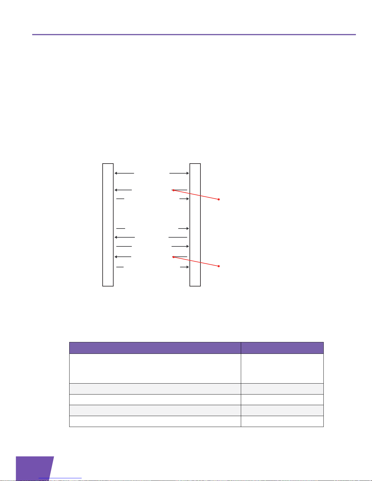
E-DOC-CTC-20071119-0003 v1.0
54
4| Monitoring and Di
agnostics
4.3 IP Ping Diagnostics Test
Introduction
The IGD data model contains the object “InternetGatewayDevice.IPPingDiagnostics.”.
This object provides access to an IP ping diagnostics test. Using TR-069, the ACS can initiate the test on the
CPE. Afterwards, the CPE reports the completion of the test to the ACS. This allows the ACS to ask for the
results of the test.
Message flow
Following illustration shows a possible message flow for the IP ping diagnostics test:
Example: parameter values
For example, following parameter values can be used:
Starting the test: the SetParameterValues RPC (message 1 in preceding illustration) contains following
name-value pairs in its ParameterList argument:
ACSCPE
Transaction session
6) Inform
(Event 8 Diagnostics Complete)
7) InformResponse
4) Close connection
2) Apply changes
10) GetParameterValuesResponse
Start the Test
1) SetParameterValues
3) SetParameterValuesResponse
8) HTTP POST (empty)
5) IP ping diagnostics test
9) GetParameterValues
Obtain the Test Results
...
...
...
Name Value
InternetGatewayDevice.IPPingDiagnostics.Interface InternetGatewayDevice.
LANDevice.1.
LANHostConfigManagement.
IPInterface.2
InternetGatewayDevice.IPPingDiagnostics.Host 192.168.1.64
InternetGatewayDevice.IPPingDiagnostics.NumberOfRepetitions 4
InternetGatewayDevice.IPPingDiagnostics.Timeout 5 (milliseconds)
InternetGatewayDevice.IPPingDiagnostics.DataBlockSize 32 (bytes)
Page 61

E-DOC-CTC-20071119-0003 v1.0
55
4| Monitoring and Diagnostics
Obtaining the test results: to retrieve the results of the test, the GetParameterValues RPC (message 9 in
preceding illustration) contains following ParameterNames argument:
For example, the GetParameterValuesResponse (message 10 in preceding illustration) contains following
name-value pairs in its ParameterList argument:
InternetGatewayDevice.IPPingDiagnostics.DSCP 0
InternetGatewayDevice.IPPingDiagnostics.DiagnosticsState Requested
Entry Value
1 InternetGatewayDevice.IPPingDiagnostics.
Name Value
InternetGatewayDevice.IPPingDiagnostics.DiagnosticsState Complete
InternetGatewayDevice.IPPingDiagnostics.SuccessCount 4
InternetGatewayDevice.IPPingDiagnostics.FailureCount 0
InternetGatewayDevice.IPPingDiagnostics.AverageResponseTime 1 (milliseconds)
InternetGatewayDevice.IPPingDiagnostics.MinimumResponseTime 1 (milliseconds)
InternetGatewayDevice.IPPingDiagnostics.MaximumResponseTime 1 (milliseconds)
Name Value
Page 62

E-DOC-CTC-20071119-0003 v1.0
56
4| Monitoring and Di
agnostics
4.4 Retrieval of the Device Log
Introduction
The IGD data model contains the DeviceLog parameter, which is located within the object
“InternetGatewayDevice.DeviceInfo.”. When the ACS asks for the device log of the CPE, it receives the
“upper” 32 Kbyte of the syslog message buffer contents.
Message flow
Following illustration shows a possible message flow for the retrieval of the device log:
Example: parameter values
To retrieve the device log, the GetParameterValues RPC (message 1 in preceding illustration) contains
following ParameterNames argument:
ACSCPE
Transaction session
Obtain the Device Log
1) GetParameterValues
2) GetParameterValuesResponse
...
...
Entry Val ue
1 InternetGatewayDevice.DeviceInfo.DeviceLog
Page 63

E-DOC-CTC-20071119-0003 v1.0
57
4| Monitoring and Diagnostics
4.5 Event Subscription
Introduction
The ACS can subscribe to particular parameter change events. When the value of such a parameter changes,
the CPE must notify the change to the ACS.
Two types of event subscription exist:
Passive change notification: whenever the parameter value changes, the CPE must include the new value
in the ParameterList argument of the Inform message that is sent the next time a session is established to
the ACS. For example, a periodic Inform or an Inform due to a Connection request.
Active change notification: whenever the parameter value changes, the CPE must initiate a session to the
ACS and include the new value in the ParameterList argument of the sent Inform message.
RPCs for event subscription
Following ACS RPCs are relevant to event subscription:
GetParameterAttributes RPC: the ACS can use this RPC to learn the event subscriptions associated with
one or more CPE parameters. The ParameterNames argument is a list of the names of the requested
parameters.
Example of the ParameterNames argument:
SetParameterAttributes RPC: the ACS can use this RPC to modify the event subscriptions associated with
one or more CPE parameters. The ParameterList argument contains the list of changes to the event
subscriptions.
Example of the ParameterList argument:
Entry Value
1 InternetGatewayDevice.Layer2Bridging. (i.e. all parameters within this object)
2 InternetGatewayDevice.DeviceInfo.SerialNumber (i.e. this specific parameter)
Entry Field Value
1
Name InternetGatewayDevice.Layer2Bridging.
NotificationChange 1 (true)
Notification 1 (passive)
2
Name InternetGatewayDevice.DeviceInfo.SerialNumber
NotificationChange 1 (true)
Notification 2 (active)
Page 64

E-DOC-CTC-20071119-0003 v1.0
58
4| Monitoring and Di
agnostics
Message flow: passive notification
Following illustration shows a possible message flow in case of passive notification:
Message flow: active notification
Following illustration shows a possible message flow in case of active notification:
ACSCPE
Transaction session
1) GetParameterAttributes
2) GetParameterAttributesResponse
...
...
4) SetParameterAttributes
5) SetParameterAttributesResponse
8) Parameter change event
6) 200 OK (Empty)
3) Verify event subscriptions,
decide to reconfigure
7) Close connection
...
9) Inform (Event 2 Periodic,
4 Value Change)
10) InformResponse
...
ACSCPE
Transaction session
1) GetParameterAttributes
2) GetParameterAttributesResponse
...
...
4) SetParameterAttributes
5) SetParameterAttributesResponse
8) Parameter change event
6) 200 OK (Empty)
3) Verify event subscriptions,
decide to reconfigure
7) Close connection
9) Inform (Event 4 Value Change)
10) InformResponse
...
Page 65

E-DOC-CTC-20071119-0003 v1.0
59
5| WAN Connections
5 WAN Connections
Introduction
The IGD data model on the Thomson Gateway contains the object
“InternetGatewayDevice.WANDevice.1.WANConnectionDevice.”.
This object can be used to create a:
PPPoE connection
PPPoA connection
IP connection with static IP address
IP connection with DHCP
IPoA connection
The IGD data model on the Thomson Gateway contains the object
“InternetGatewayDevice.Layer3Forwarding.Forwarding.”. This object can be used to create forwarding
entries.
Message flow
Following illustration shows a possible message flow for the creation and configuration of a WAN
connection:
ACSCPE
Transaction session
5) Apply changes
Configure the WAN Connection Device
4) SetParameterValues
6) SetParameterValuesResponse
...
11) Apply changes
Configure the WANPPPConnection or WANIPConnection
10) SetParameterValues
12) SetParameterValuesResponse
Create a WAN Connection Device
1) AddObject
3) AddObjectResponse
2) Apply changes
Obtain Connection Information and
Forwarding Entries
13) GetParameterValues
14) GetParameterValuesResponse
...
Create a WANPPPConnection or WANIPConnection
7) AddObject
9) AddObjectResponse
8) Apply changes
19) Apply changes
Configure the Forwarding Entry
18) SetParameterValues
20) SetParameterValuesResponse
Create a Forwarding Entry
15) AddObject
17) AddObjectResponse
16) Apply changes
Page 66

E-DOC-CTC-20071119-0003 v1.0
60
5| WAN Connections
Overview
Following steps must be performed to create a WAN connection:
1 Create and configure a WAN connection device. See “5.1 WAN Connection Device” on page 61.
2 Create and configure a WAN PPP or IP connection. See “5.2 WAN PPP or IP Connection” on page 62.
3 Obtain connection information. See “5.3 Connection Information” on page 65.
4 Create and configure a forwarding entry. See “5.4 Forwarding Entries” on page 66.
Page 67

E-DOC-CTC-20071119-0003 v1.0
61
5| WAN Connections
5.1 WAN Connection Device
WAN connection device
A WAN connection device can be created and configured as follows:
Creating a WAN connection device: the AddObject RPC (message 1 in preceding illustration) contains for
the ObjectName argument the value “InternetGatewayDevice.WANDevice.1.WANConnectionDevice.”.
The AddObjectResponse (message 3 in preceding illustration) contains for the InstanceNumber
argument for example value “2“.
Configuring the WAN connection device: to create and configure the ATM PVC, the SetParameterValues
RPC (message 4 in preceding illustration) contains following name-value pairs in its ParameterList
argument:
Link type value
Following table shows the link type of a specific WAN connection:
Name Value
InternetGatewayDevice.WANDevice.1.WANConnectionDevice.2.
WANDSLLinkConfig.LinkType
EoA, PPPoA or IPoA
See “ Link type value”.
InternetGatewayDevice.WANDevice.1.WANConnectionDevice.2.
WANDSLLinkConfig.DestinationAddress
8/35 (VP/VC)
InternetGatewayDevice.WANDevice.1.WANConnectionDevice.2.
WANDSLLinkConfig.ATMEncapsulation
LLC or VCMUX
InternetGatewayDevice.WANDevice.1.WANConnectionDevice.2.
WANDSLLinkConfig.Enable
1
WAN connection Link type
PPPoE EoA
IP EoA
PPPoA PPPoA
IPoA IPoA
Page 68

E-DOC-CTC-20071119-0003 v1.0
62
5| WAN Connections
5.2 WAN PPP or IP Connection
Introduction
Before, configuring your WAN PPP or IP connection, make sure that you created and configured a WAN
connection device. For more information, see “5.1 WAN Connection Device” on page 61.
WAN PPPoE connection
A WAN PPPoE connection can be created and configured as follows:
Creating a PPPoE connection: the AddObject RPC (message 7 in preceding illustration) contains for the
ObjectName argument the value
“InternetGatewayDevice.WANDevice.1.WANConnectionDevice.2.WANPPPConnection.”.
The AddObjectResponse (message 9 in preceding illustration) contains for the InstanceNumber
argument for example value “1“.
Configuring the PPPoE connection: the SetParameterValues RPC (message 10 in preceding illustration)
contains following name-value pairs in its ParameterList argument:
WAN PPPoA connection
A WAN PPPoA connection can be created and configured as follows:
Creating a PPPoA connection: the AddObject RPC (message 7 in preceding illustration) contains for the
ObjectName argument the value
“InternetGatewayDevice.WANDevice.1.WANConnectionDevice.2.WANPPPConnection.”.
The AddObjectResponse (message 9 in preceding illustration) contains for the InstanceNumber
argument for example value “1“.
Name Value
InternetGatewayDevice.WANDevice.1.WANConnectionDevice.2.
WANPPPConnection.1.NATEnabled
1
InternetGatewayDevice.WANDevice.1.WANConnectionDevice.2.
WANPPPConnection.1.Username
<username>
InternetGatewayDevice.WANDevice.1.WANConnectionDevice.2.
WANPPPConnection.1.Password
<password>
InternetGatewayDevice.WANDevice.1.WANConnectionDevice.2.
WANPPPConnection.1.Name
Internet
InternetGatewayDevice.WANDevice.1.WANConnectionDevice.2.
WANPPPConnection.1.Enable
1
The parameter Name is mandatory. This means that the parameter must be set before the
WANPPPConnection object is internally created.
Page 69

E-DOC-CTC-20071119-0003 v1.0
63
5| WAN Connections
Configuring the PPPoA connection: the SetParameterValues RPC (message 10 in preceding illustration)
contains following name-value pairs in its ParameterList argument:
WAN IP connection with static IP address
A WAN IP connection with a static IP address can be created and configured as follows:
Creating an IP connection: the AddObject RPC (message 7 in preceding illustration) contains for the
ObjectName argument the value
“InternetGatewayDevice.WANDevice.1.WANConnectionDevice.2.WANIPConnection.”.
The AddObjectResponse (message 9 in preceding illustration) contains for the InstanceNumber
argument for example value “1“.
Configuring the IP connection with a static IP address: the SetParameterValues RPC (message 10 in
preceding illustration) contains following name-value pairs in its ParameterList argument:
Name Value
InternetGatewayDevice.WANDevice.1.WANConnectionDevice.2.
WANPPPConnection.1.NATEnabled
1
InternetGatewayDevice.WANDevice.1.WANConnectionDevice.2.
WANPPPConnection.1.Username
<username>
InternetGatewayDevice.WANDevice.1.WANConnectionDevice.2.
WANPPPConnection.1.Password
<password>
InternetGatewayDevice.WANDevice.1.WANConnectionDevice.2.
WANPPPConnection.1.Name
Internet
InternetGatewayDevice.WANDevice.1.WANConnectionDevice.2.
WANPPPConnection.1.Enable
1
The parameter Name is mandatory. This means that the parameter must be set before the
WANPPPConnection object is internally created.
Name Value
InternetGatewayDevice.WANDevice.1.WANConnectionDevice.2.
WANIPConnection.1.AddressingType
Static
InternetGatewayDevice.WANDevice.1.WANConnectionDevice.2.
WANIPConnection.1.ExternalIPAddress
<ipaddress>
InternetGatewayDevice.WANDevice.1.WANConnectionDevice.2.
WANIPConnection.1.SubnetMask
<mask>
InternetGatewayDevice.WANDevice.1.WANConnectionDevice.2.
WANIPConnection.1.Name
Video
InternetGatewayDevice.WANDevice.1.WANConnectionDevice.2.
WANIPConnection.1.Enable
1
The parameter Name is mandatory. This means that the parameter must be set before the
WANIPConnection object is internally created.
Page 70

E-DOC-CTC-20071119-0003 v1.0
64
5| WAN Connections
WAN IP connection with DHCP
A WAN IP connection with DHCP can be created and configured as follows:
Creating an IP connection: the AddObject RPC (message 7 in preceding illustration) contains for the
ObjectName argument the value
“InternetGatewayDevice.WANDevice.1.WANConnectionDevice.2.WANIPConnection.”.
The AddObjectResponse (message 9 in preceding illustration) contains for the InstanceNumber
argument for example value “1“.
Configuring the IP connection with DHCP: the SetParameterValues RPC (message 10 in preceding
illustration) contains following name-value pairs in its ParameterList argument:
WAN IPoA connection
A WAN IPoA connection can be created and configured as follows:
Creating an IPoA connection: the AddObject RPC (message 7 in preceding illustration) contains for the
ObjectName argument the value
“InternetGatewayDevice.WANDevice.1.WANConnectionDevice.2.WANIPConnection.”.
The AddObjectResponse (message 9 in preceding illustration) contains for the InstanceNumber
argument for example value “1“.
Configuring the IPoA connection: the SetParameterValues RPC (message 10 in preceding illustration)
contains following name-value pairs in its ParameterList argument:
Name Value
InternetGatewayDevice.WANDevice.1.WANConnectionDevice.2.
WANIPConnection.1.AddressingType
DHCP
InternetGatewayDevice.WANDevice.1.WANConnectionDevice.2.
WANIPConnection.1.Name
Video
InternetGatewayDevice.WANDevice.1.WANConnectionDevice.2.
WANIPConnection.1.Enable
1
The parameter Name is mandatory. This means that the parameter must be set before the
WANIPConnection object is internally created.
Name Value
InternetGatewayDevice.WANDevice.1.WANConnectionDevice.2.
WANIPConnection.1.AddressingType
Static
InternetGatewayDevice.WANDevice.1.WANConnectionDevice.2.
WANIPConnection.1.ExternalIPAddress
<ipaddress>
InternetGatewayDevice.WANDevice.1.WANConnectionDevice.2.
WANIPConnection.1.SubnetMask
<subnetmask>
InternetGatewayDevice.WANDevice.1.WANConnectionDevice.2.
WANIPConnection.1.Name
Video
InternetGatewayDevice.WANDevice.1.WANConnectionDevice.2.
WANIPConnection.1.Enable
1
The parameter Name is mandatory. This means that the parameter must be set before the
WANIPConnection object is internally created.
Page 71

E-DOC-CTC-20071119-0003 v1.0
65
5| WAN Connections
5.3 Connection Information
PPP connection
To obtain information on the connection status, the assigned external IP address and forwarding entries, the
GetParameterValues RPC (message 13 in preceding illustration) contains following ParameterNames
arguments:
IP connection
To obtain information on the connection status, the assigned external IP address and the forwarding entries,
the GetParameterValues RPC (message 13 in preceding illustration) contains following ParameterNames
arguments:
Entry Value
1 InternetGatewayDevice.WANDevice.1.WANConnectionDevice.2.WANPPPConnection.1
2 InternetGatewayDevice.Layer3Forwarding.Forwarding
Entry Value
1 InternetGatewayDevice.WANDevice.1.WANConnectionDevice.2.WANIPConnection.1
2 InternetGatewayDevice.Layer3Forwarding.Forwarding
Page 72

E-DOC-CTC-20071119-0003 v1.0
66
5| WAN Connections
5.4 Forwarding Entries
PPP connection
For example, following parameter values can be used:
Creating an entry: to add a forwarding entry, the AddObject RPC (message 15 in preceding illustration)
contains for the ObjectName argument the value
“InternetGatewayDevice.Layer3Forwarding.Forwarding.”.
The AddObjectResponse (message 17 in preceding illustration) contains for the InstanceNumber
argument for example value “3“.
Configuring the entry: the SetParameterValues RPC (message 18 in preceding illustration) contains
following name-value pairs in its ParameterList argument, for example to add a default route:
IP connection
For example, following parameter values can be used:
Creating an entry: to add a forwarding entry, the AddObject RPC (message 15 in preceding illustration)
contains for the ObjectName argument the value
“InternetGatewayDevice.Layer3Forwarding.Forwarding.”.
The AddObjectResponse (message 17 in preceding illustration) contains for the InstanceNumber
argument for example value “3“.
Configuring the entry: the SetParameterValues RPC (message 18 in preceding illustration) contains
following name-value pairs in its ParameterList argument, for example to add a default route:
Name Val ue
InternetGatewayDevice.Layer3Forwarding.Forwarding.3.DestIPAddress0.0.0.0
InternetGatewayDevice.Layer3Forwarding.Forwarding.3.
DestSubnetMask
0.0.0.0
InternetGatewayDevice.Layer3Forwarding.Forwarding.3.
Interface
IGD.WANDevice.1.
WANConnectionDevice.2.
WANPPPConnection.1
InternetGatewayDevice.Layer3Forwarding.Forwarding.3.
ForwardingMetric
1
InternetGatewayDevice.Layer3Forwarding.Forwarding.3.
GatewayIPAddress
<ipaddress_Interface>
The parameters DestIPAddress, Interface and GatewayIPAddress are mandatory. This means
that these parameters must be set before the Forwarding object is internally created.
Name Value
InternetGatewayDevice.Layer3Forwarding.Forwarding.3.DestIPAddress0.0.0.0
InternetGatewayDevice.Layer3Forwarding.Forwarding.3.DestSubnet
Mask
0.0.0.0
Page 73

E-DOC-CTC-20071119-0003 v1.0
67
5| WAN Connections
InternetGatewayDevice.Layer3Forwarding.Forwarding.3.Interface IGD.WANDevice.1.
WANConnectionDevice.2.
WANIPConnection.1
InternetGatewayDevice.Layer3Forwarding.Forwarding.3.Forwarding
Metric
1
InternetGatewayDevice.Layer3Forwarding.Forwarding.3.GatewayIPAd
dress
<ipaddress_Interface>
The parameters DestIPAddress, Interface and GatewayIPAddress are mandatory. This means
that these parameters must be set before the Forwarding object is internally created.
Name Value
Page 74

E-DOC-CTC-20071119-0003 v1.0
68
5| WAN Connections
Page 75

E-DOC-CTC-20071119-0003 v1.0
69
6| Service Provisioning
6 Service Provisioning
Introduction
Service activation based on the data model can be part of the zero-provisioning use case or can be used at
any point in time. For example, the user has a VoIP-capable Thomson Gateway but only after an amount of
time decides to subscribe to the VoIP service.
Overview
This chapter includes following use cases:
For more information on the non vendor specific parameters in the data model, see TR-098.
Topi c Page
“6.1 VoIP” 70
“6.2 WLAN” 73
“6.3 Time” 76
“6.4 DHCP Conditional Serving” 77
“6.5 Queue Management” 79
“6.6 Stateful Inspection Firewall” 81
“6.7 Access Rights” 85
“6.8 NAT Application List” 87
“6.9 Dynamic DNS” 90
“6.10 Remote Access (Remote Assistance)” 93
“6.11 Parental Control” 95
“6.12 VLAN Provisioning (Layer2Bridging)” 97
Page 76

E-DOC-CTC-20071119-0003 v1.0
70
6| Service Provisionin
g
6.1 VoIP
Introduction
Because any configuration problem might lead to VoIP service unavailability and help-desk calls, remote
management of VoIP parameters (SIP URI, server addresses, authentication…) ensures a fluent VoIP service
activation.
VoiceService data model
The IGD data model contains the object “InternetGatewayDevice.Services.VoiceService.”.
This object contains the objects and parameters needed to:
Enable or disable the VoIP service
Configure the VoIP settings
Troubleshoot the VoIP service
The VoiceService data model of the Thomson Gateway provides support for the SIP, MGCP and H.323
signalling protocols.
Vendor specific parameters
The VoiceService data model of the Thomson Gateway contains following vendor specific objects and
parameters:
VoiceService parameters and objects:
VoiceService.[i].X_000E50_AreaCode: the geographical number. Setting the AreaCode at IGD level
overrules the NumberingPlan at IGD level (B2BUA).
VoiceService.[i].X_000E50_MaxSessions: the maximum number of simultaneous sessions.
VoiceService.[i].X_000E50_UAMappingNumberOfEntries: the number of entries in the UA mapping table.
In case of a Back-to-Back User Agent, this is a global to local UA mapping table. In case of a local Back-toBack User Agent, this is a local to global UA mapping table. Each entry is defined by an
X_000E50_UAMapping object.
VoiceService.[i].X_000E50_UAMapping.: an entry in the UA mapping table, defined by two parameters:
FromUA: a cross-reference to a Line object instance.
ToUA : a cross-reference to a Line object instance.
VoiceService.VoiceProfile.Line parameters and objects:
VoiceService.[i].VoiceProfile.[i].Line.[i].X_000E50_Interface: a cross-reference to a WANIPConnection or
WANPPPConnection object.
VoiceService.[i].VoiceProfile.[i].Line.[i].X_000E50_RegistrationNumberOfEntries: the number of
registrations. Each registration is defined by a X_000E50_Registration object.
VoiceService.[i].VoiceProfile.[i].Line.[i].X_000E50_Registration.: a registration is defined by three
parameters:
ContactIPAddress
ContactPort
ExpireTimeout
For more information on the VoiceService data model, see TR-104 “Provisioning parameters for
VoIP CPE”, September 2005.
Page 77

E-DOC-CTC-20071119-0003 v1.0
71
6| Service Provisioning
Message flow
Following illustration shows a possible message flow for voice service provisioning:
Example: parameter values for a User Agent
For example, following parameter values can be used:
Checking the current configuration: to obtain information on the current voice configuration, the
GetParameterValues RPC (message 1 in preceding illustration) contains following ParameterNames
argument:
For example, the GetParameterValuesResponse (message 2 in preceding illustration) contains, amongst
others, following name-value pair in its ParameterList argument:
Configuring the voice profile: if necessary, modify the value of one or more parameters and finally enable
the VoiceProfile.1. object instance. The SetParameterValues RPC (message 3 in preceding illustration)
contains following name-value pair in its ParameterList argument:
ACSCPE
Transaction session
4) Apply changes
Configure the VoiceProfile
3) SetParameterValues
5) SetParameterValuesResponse
...
7) Apply changes
Configure the SIP signalling protocol
6) SetParameterValues
8) SetParameterValuesResponse
Create a Line
9) AddObject
11) AddObjectResponse
10) Apply changes
13) Apply changes
Configure the Line
12) SetParameterValues
14) SetParameterValuesResponse
...
Obtain current Configuration
1) GetParameterValues
2) GetParameterValuesResponse
Entry Value
1 InternetGatewayDevice.Services.VoiceService.
Name Value
InternetGatewayDevice.Services.VoiceService.1.VoiceProfile.1.SignalingProtocol SIP
Name Value
InternetGatewayDevice.Services.VoiceService.1.VoiceProfile.1.Enable Enabled
Page 78

E-DOC-CTC-20071119-0003 v1.0
72
6| Service Provisionin
g
Configuring the signalling protocol: if necessary, modify the value of one or more parameters. The
SetParameterValues RPC (message 6 in preceding illustration) contains following name-value pairs in its
ParameterList argument:
Creating a voice account: the AddObject RPC (message 9 in preceding illustration) contains for the
ObjectName argument the value “InternetGatewayDevice.Services.VoiceService.1.VoiceProfile.1.Line.”.
The AddObjectResponse (message 11 in preceding illustration) contains for the InstanceNumber
argument for example value “1”.
Configuring the voice account: if necessary, modify the value of one or more parameters. To enable the
Line.1 object instance, following parameters must be modified (a PhyReferenceList value equal to 1
corresponds to the FXS1 port). The data model will not be updated as long as the PhyReferenceList
parameter (i.e. the voice port) is not set. The SetParameterValues RPC (message 12 in preceding
illustration) contains following name-value pairs in its ParameterList argument:
Name Value
InternetGatewayDevice.Services.VoiceService.1.VoiceProfile.1.SIP.ProxyServer <ip_address
>
InternetGatewayDevice.Services.VoiceService.1.VoiceProfile.1.SIP.ProxyServerPort <port>
InternetGatewayDevice.Services.VoiceService.1.VoiceProfile.1.SIP.RegistrarServer <ip_address
>
InternetGatewayDevice.Services.VoiceService.1.VoiceProfile.1.SIP.
RegistrarServerPort
<port>
Name Value
InternetGatewayDevice.Services.VoiceService.1.VoiceProfile.1.Line.1.Enable Enabled
InternetGatewayDevice.Services.VoiceService.1.VoiceProfile.1.Line.1.
PhyReferenceList
1
InternetGatewayDevice.Services.VoiceService.1.VoiceProfile.1.Line.1.SIP.
AuthUserName
<user name>
InternetGatewayDevice.Services.VoiceService.1.VoiceProfile.1.Line.1.SIP.
AuthPassword
<password>
InternetGatewayDevice.Services.VoiceService.1.VoiceProfile.1.Line.1.SIP.URI <my voice
number>
The parameter PhyReferenceList is mandatory. This means that the parameter must be set
before the Line object is internally created.
Page 79

E-DOC-CTC-20071119-0003 v1.0
73
6| Service Provisioning
6.2 WLAN
Introduction
Given the increasing deployment of wireless gateways and the known complexity of setting up a secure
wireless LAN network, remote management of wireless settings can lower the complexity for the end-user.
For example, remote management can configure or reset the SSID to a “default value” and configure the
security settings. The end-user does not need to manually configure the Thomson Gateway. Given a
broadcasted SSID and preconfigured security settings, the end-user must only configure the WEP or WPA key
on its PC. Remote management can also reset wireless settings to defaults that are provided to the end-user,
turn off security to allow the user to associate and configure again.
WLANConfiguration data model
The IGD data model on the Thomson Gateway contains the object
“InternetGatewayDevice.LANDevice.1.WLANConfiguration.1.”.
This object contains the objects and parameters needed for the configuration of the wireless service:
Enable or disable the wireless service.
Configure the wireless settings.
Troubleshoot the wireless service.
Vendor specific parameters
The WLANConfiguration data model on the Thomson Gateway contains following vendor specific parameter:
X_000E50_ChannelMode: this parameter can be used to request automatic selection of the channel. The
parameter has one of the following values:
Auto (default value)
Manual
Message flow
Following illustration shows a possible message flow for wireless service provisioning:
ACSCPE
Transaction session
2) Apply changes
Configure the Wireless Service
1) SetParameterValues
3) SetParameterValuesResponse
...
...
Page 80

E-DOC-CTC-20071119-0003 v1.0
74
6| Service Provisionin
g
Example: parameter values
For example, following parameter values can be used:
Configuration in case of no security: the SetParameterValues RPC (message 1 in preceding illustration)
contains following name-value pairs in its ParameterList argument:
Configuration in case of WEP: the SetParameterValues RPC (message 1 in preceding illustration) contains
following name-value pairs in its ParameterList argument:
Configuration in case of WPA: the SetParameterValues RPC (message 1 in preceding illustration) contains
following name-value pairs in its ParameterList argument:
Configuration in case of WPA2: the SetParameterValues RPC (message 1 in preceding illustration)
contains following name-value pairs in its ParameterList argument:
Name Val ue
InternetGatewayDevice.LANDevice.1.WLANConfiguration.1.Channel <channel_id>
InternetGatewayDevice.LANDevice.1.WLANConfiguration.1.BeaconType None
InternetGatewayDevice.LANDevice.1.WLANConfiguration.1.SSID <SSID>
InternetGatewayDevice.LANDevice.1.WLANConfiguration.1.Enable 1
Name Val ue
InternetGatewayDevice.LANDevice.1.WLANConfiguration.1.WEPKey.1.WEPKey1234567890
InternetGatewayDevice.LANDevice.1.WLANConfiguration.1.Channel <channel_id>
InternetGatewayDevice.LANDevice.1.WLANConfiguration.1.BeaconType Basic
InternetGatewayDevice.LANDevice.1.WLANConfiguration.1.SSID <SSID>
InternetGatewayDevice.LANDevice.1.WLANConfiguration.1.Enable 1
Name Val ue
InternetGatewayDevice.LANDevice.1.WLANConfiguration.1.PreSharedKey.1.
KeyPassphrase
abcdefgh
InternetGatewayDevice.LANDevice.1.WLANConfiguration.1.Channel <channel_id>
InternetGatewayDevice.LANDevice.1.WLANConfiguration.1.BeaconType WPA
InternetGatewayDevice.LANDevice.1.WLANConfiguration.1.SSID <SSID>
InternetGatewayDevice.LANDevice.1.WLANConfiguration.1.Enable 1
Name Val ue
InternetGatewayDevice.LANDevice.1.WLANConfiguration.1.PreSharedKey.1.
KeyPassphrase
abcdefgh
InternetGatewayDevice.LANDevice.1.WLANConfiguration.1.Channel <channel_id>
InternetGatewayDevice.LANDevice.1.WLANConfiguration.1.BeaconType 11i
InternetGatewayDevice.LANDevice.1.WLANConfiguration.1.SSID <SSID>
InternetGatewayDevice.LANDevice.1.WLANConfiguration.1.Enable 1
Page 81

E-DOC-CTC-20071119-0003 v1.0
75
6| Service Provisioning
Configuration in case of WPA and WPA2: the SetParameterValues RPC (message 1 in preceding
illustration) contains following name-value pairs in its ParameterList argument:
Name Val ue
InternetGatewayDevice.LANDevice.1.WLANConfiguration.1.PreSharedKey.1.
KeyPassphrase
abcdefgh
InternetGatewayDevice.LANDevice.1.WLANConfiguration.1.Channel <channel_id>
InternetGatewayDevice.LANDevice.1.WLANConfiguration.1.BeaconType WPAand11i
InternetGatewayDevice.LANDevice.1.WLANConfiguration.1.SSID <SSID>
InternetGatewayDevice.LANDevice.1.WLANConfiguration.1.Enable 1
Page 82

E-DOC-CTC-20071119-0003 v1.0
76
6| Service Provisionin
g
6.3 Time
Time data model
The IGD data model on the Thomson Gateway contains the object “InternetGatewayDevice.Time.”.
This object can be used to:
Configure the NTP server IP addresses.
Enable the NTP service.
Vendor specific parameters
The Time data model on the Thomson Gateway contains following vendor specific parameters:
X_000E50_WeekDay: the day of the week (Monday, Tuesday,...).
X_000E50_Enable: used to enable or disable the NTP service.
Message flow
Following illustration shows a possible message flow for NTP service provisioning:
Example: parameter values
For example, following parameter values can be used:
the SetParameterValues RPC (message 1 in preceding illustration) contains following name-value pairs
in its ParameterList argument:
ACSCPE
Transaction session
...
2) Apply changes
Configure the Time service
1) SetParameterValues
3) SetParameterValuesResponse
...
Name Value
InternetGatewayDevice.Time.NTPServer1 <hostname> or <ipaddress>
InternetGatewayDevice.Time.X_000E50_Enable 1
Page 83

E-DOC-CTC-20071119-0003 v1.0
77
6| Service Provisioning
6.4 DHCP Conditional Serving
DHCPConditionalServingPool data model
The IGD data model contains the object
“InternetGatewayDevice.LANDevice.1.LANHostConfigManagement.DHCPConditionalServingPool.”.
This object supports conditional serving, which allows to:
Serve specific devices from a specific pool.
Define DHCP options served to those specific devices.
Vendor specific parameters
There are no vendor specific parameters.
Message flow
Following illustration shows a possible message flow for the configuration of DHCP conditional serving:
Example: parameter values
For example, following parameter values can be used:
Creating a serving pool: the AddObject RPC (message 1 in preceding illustration) contains for the
ObjectName argument the value
“InternetGatewayDevice.LANDevice.1.LANHostConfigManagement.DHCPConditionalServingPool.”.
The AddObjectResponse (message 3 in preceding illustration) contains for the InstanceNumber
argument for example value “1”.
For more information on the DHCPConditionalServingPool data model, see WT-107 “Internet
Gateway Device data model (TR-098 issue 2)”, September 2006.
ACSCPE
Transaction session
...
5) Apply changes
Configure the DHCP Conditional Serving Pool
4) SetParameterValues
6) SetParameterValuesResponse
Create a DHCP Conditional Serving Pool
1) AddObject
3) AddObjectResponse
2) Apply changes
Create a DHCP Option
7) AddObject
9) AddObjectResponse
8) Apply changes
11) Apply changes
Configure the DHCP Option
10) SetParameterValues
12) SetParameterValuesResponse
...
Page 84

E-DOC-CTC-20071119-0003 v1.0
78
6| Service Provisionin
g
Configuring the serving pool: the SetParameterValues RPC (message 4 in preceding illustration) contains
following name-value pairs in its ParameterList argument:
Creating a DHCP option: the AddObject RPC (message 7 in preceding illustration) contains for the
ObjectName argument the value
“InternetGatewayDevice.LANDevice.1.LANHostConfigManagement.DHCPConditionalServingPool.1.
DHCPOption.”.
The AddObjectResponse (message 9 in preceding illustration) contains for the InstanceNumber
argument for example value “1”.
Configuring the DHCP option: the SetParameterValues RPC (message 10 in preceding illustration)
contains following name-value pairs in its ParameterList argument:
Name Value
InternetGatewayDevice.LANDevice.1.LANHostConfigManagement
.DHCPConditionalServingPool.1.Chaddr
00:0f:1f:83:d7:5b
InternetGatewayDevice.LANDevice.1.LANHostConfigManagement
.DHCPConditionalServingPool.1.MinAddress
192.168.1.70
InternetGatewayDevice.LANDevice.1.LANHostConfigManagement
.DHCPConditionalServingPool.1.MaxAddress
192.168.1.80
InternetGatewayDevice.LANDevice.1.LANHostConfigManagement
.DHCPConditionalServingPool.1.SubnetMask
255.255.255.0
InternetGatewayDevice.LANDevice.1.LANHostConfigManagement
.DHCPConditionalServingPool.1.IPRouters
192.168.1.254
InternetGatewayDevice.LANDevice.1.LANHostConfigManagement
.DHCPConditionalServingPool.1.DHCPLeaseTime
86400
Name Value
InternetGatewayDevice.LANDevice.1.LANHostConfigManagement
.DHCPConditionalServingPool.1.DHCPOption.1.Tag
4
InternetGatewayDevice.LANDevice.1.LANHostConfigManagement
.DHCPConditionalServingPool.1.DHCPOption.1.Value
“MTIzNDU2Nzg=”
The parameters Tag and Value are mandatory. This means that these parameters must be set
before the DHCPOption object is internally created.
Page 85

E-DOC-CTC-20071119-0003 v1.0
79
6| Service Provisioning
6.5 Queue Management
QueueManagement data model
The IGD data model on the Thomson Gateway contains the object
“InternetGatewayDevice.QueueManagement.” for the support of QoS provisioning.
This object contains the following multi-instance objects:
Classification.[i]
Queue.[i]
Policer.[i]: only supported on a number of products
Vendor specific parameters
There are no vendor specific parameters.
Message flow
Following illustration shows a possible message flow for QoS provisioning:
Example: parameter values
For example, following parameter values can be used:
Configuring a queue table entry: the SetParameterValues RPC (message 1 in preceding illustration)
contains following name-value pairs in its ParameterList argument:
ACSCPE
Transaction session
...
8) Apply changes
Configure the Classification table entry
7) SetParameterValues
9) SetParameterValuesResponse
Create a Classification table entry
4) AddObject
6) AddObjectResponse
5) Apply changes
Create a Policer table entry
10) AddObject
12) AddObjectResponse
11) Apply changes
14) Apply changes
Configure the Policer table entry
13) SetParameterValues
15) SetParameterValuesResponse
...
2) Apply changes
Configure a Queue table entry
1) SetParameterValues
3) SetParameterValuesResponse
Name Value
InternetGatewayDevice.QueueManagement.Queue.6.QueueInterface WAN
Page 86

E-DOC-CTC-20071119-0003 v1.0
80
6| Service Provisionin
g
Creating a classification table entry: the AddObject RPC (message 4 in preceding illustration) contains for
the ObjectName argument the value “InternetGatewayDevice.QueueManagement.Classification.”.
The AddObjectResponse (message 6 in preceding illustration) contains for the InstanceNumber
argument for example value “24”.
Configuring the classification table entry: the SetParameterValues RPC (message 7 in preceding
illustration) contains following name-value pairs in its ParameterList argument:
Creating a policer table entry: the AddObject RPC (message 10 in preceding illustration) contains for the
ObjectName argument the value “InternetGatewayDevice.QueueManagement.Policer.”.
The AddObjectResponse (message 12 in preceding illustration) contains for the InstanceNumber
argument for example value “1”.
Configuring the policer table entry: the SetParameterValues RPC (message 13 in preceding illustration)
contains following name-value pairs in its ParameterList argument:
InternetGatewayDevice.QueueManagement.Queue.6.DropAlgorithm BLUE
InternetGatewayDevice.QueueManagement.Queue.6.SchedulerAlgorithmWFQ
InternetGatewayDevice.QueueManagement.Queue.6.QueueEnable 1
Name Value
InternetGatewayDevice.QueueManagement.Classification.24.Protocol 6
InternetGatewayDevice.QueueManagement.Classification.24.DSCPMark -1
InternetGatewayDevice.QueueManagement.Classification.24.ForwardingPolicy 0
InternetGatewayDevice.QueueManagement.Classification.24.ClassQueue 6
InternetGatewayDevice.QueueManagement.Classification.24.ClassPolicer -1
InternetGatewayDevice.QueueManagement.Classification.24.ClassificationEnable 1
Name Value
InternetGatewayDevice.QueueManagement.Policer.1.PolicerEnable 1
Name Value
Page 87

E-DOC-CTC-20071119-0003 v1.0
81
6| Service Provisioning
6.6 Stateful Inspection Firewall
Firewall data model
The IGD data model on the Thomson Gateway contains the object
“InternetGatewayDevice.X_000E50_Firewall.”.
This data model can be used to:
Create and configure new security levels, e.g. to create an expert firewall service with 10 levels instead of
the default 3 levels.
Temporary update existing firewall chains and rules, e.g. to protect the network against new worms,
viruses or Trojans alerts.
The Thomson Gateway supports following proprietary Firewall data model:
Name Type Actions
InternetGatewayDevice.X_000E50_Firewall. Object
Enable Parameter Read/Write
SelectedLevel Parameter Read/Write
LevelNumberOfEntries Parameter Read
ChainNumberOfEntries Parameter Read
Level. Object Add/Delete
Name Parameter Read/Write
Order Parameter Read/Write
Description Parameter Read/Write
ReadOnly Parameter Read/Write
DefaultPolicy Parameter Read/Write
Chain Parameter Read
RespondToPing Parameter Read/Write
Chain. Object Add/Delete
Name Parameter Read/Write
Type Parameter Read
RuleNumberOfEntries Parameter Read
Rule.[i]. Object Add/Delete
Status Parameter Read
Order Parameter Read/Write
Description Parameter Read/Write
Ta rg et Parameter Read/Write
TargetChain Parameter Read/Write
Page 88

E-DOC-CTC-20071119-0003 v1.0
82
6| Service Provisionin
g
SourceIP Parameter Read/Write
SourceIPMask Parameter Read/Write
SourceIPExclude Parameter Read/Write
DestinationIP Parameter Read/Write
DestinationIPMask Parameter Read/Write
DestinationIPExclude
Parameter Read/Write
SourceInterface Parameter Read/Write
SourceInterfaceExclude
Parameter Read/Write
DestinationInterface
Parameter Read/Write
DestinationInterfaceExclude
Parameter Read/Write
Protocol Parameter Read/Write
ProtocolExclude Parameter Read/Write
SourcePort Parameter Read/Write
SourcePortRangeEnd
Parameter Read/Write
SourcePortExclude
Parameter Read/Write
DestinationPort Parameter Read/Write
DestinationPortRangeEnd
Parameter Read/Write
DestinationPortExclude
Parameter Read/Write
TOS Parameter Read/Write
TOSExclude Parameter Read/Write
DSCP Parameter Read/Write
DSCPExclude Parameter Read/Write
SourceMACAddress
Parameter Read/Write
SourceMACMask Parameter Read/Write
SourceMACExclude
Parameter Read/Write
Enable Parameter Read/Write
Name Type Actions
Page 89
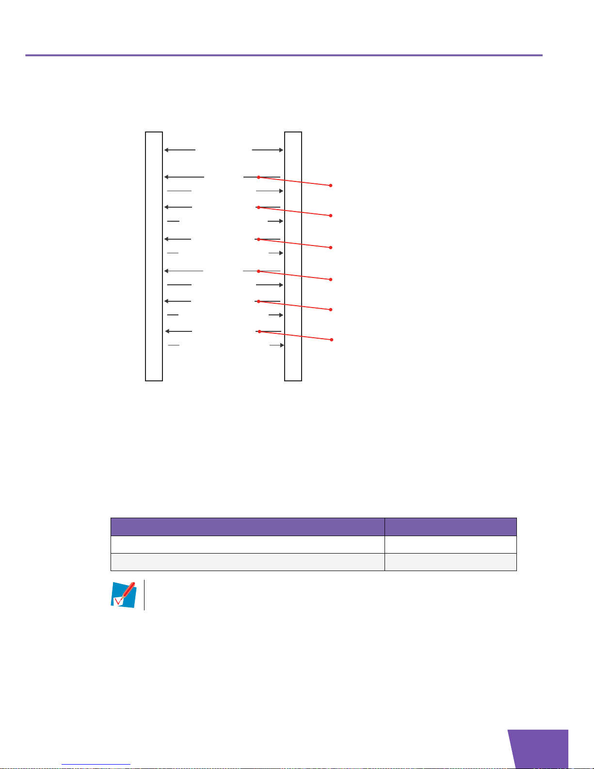
E-DOC-CTC-20071119-0003 v1.0
83
6| Service Provisioning
Message flow
Following illustration shows a possible message flow for the firewall configuration:
Example: parameter values
For example, following parameter values can be used:
Creating a security level: the AddObject RPC (message 1 in preceding illustration) contains for the
ObjectName argument the value “InternetGatewayDevice.X_000E50_Firewall.Level.”.
The AddObjectResponse (message 3 in preceding illustration) contains for the InstanceNumber
argument for example value “7“.
Configuring the security level: the SetParameterValues RPC (message 4 in preceding illustration)
contains following name-value pairs in its ParameterList argument:
ACSCPE
Transaction session
...
5) Apply changes
Configure the Security Level
4) SetParameterValues
6) SetParameterValuesResponse
Create a Security Level
1) AddObject
3) AddObjectResponse
2) Apply changes
Create a Rule
9) AddObject
11) AddObjectResponse
10) Apply changes
13) Apply changes
Configure the Rule
12) SetParameterValues
14) SetParameterValuesResponse
...
16) Apply changes
Activate the Security Level
15) SetParameterValues
17) SetParameterValuesResponse
Obain the corresponding Firewall Chain
7) GetParameterValues
8) GetParameterValuesResponse
Name Value
InternetGatewayDevice.X_000E50_Firewall.Level.7.Name TestLevel
InternetGatewayDevice.X_000E50_Firewall.Level.7.Description “This is a test”
The parameter Name is mandatory. This means that the parameter must be set before the
Level object is internally created.
Page 90

E-DOC-CTC-20071119-0003 v1.0
84
6| Service Provisionin
g
Finding the new chain: the Thomson Gateway automatically creates a new chain that is used by the new
security level. The GetParameterValues RPC (message 7 in preceding illustration) contains following
ParameterNames argument:
The GetParameterValuesResponse (message 8 in preceding illustration) contains for example value
“InternetGatewayDevice.X_000E50_Firewall.Chain.20”.
Creating a rule: the AddObject RPC (message 9 in preceding illustration) contains for the ObjectName
argument the value “InternetGatewayDevice.X_000E50_Firewall.Chain.20.Rule.”.
The AddObjectResponse (message 11 in preceding illustration) contains for the InstanceNumber
argument for example value “1“.
Configuring the rule: the SetParameterValues RPC (message 12 in preceding illustration) contains
following name-value pairs in its ParameterList argument:
Activating the security level: the SetParameterValues RPC (message 15 in preceding illustration)
contains following name-value pair in its ParameterList argument:
Entry Value
1 InternetGatewayDevice.X_000E50_Firewall.Level.7.Chain
Name Value
InternetGatewayDevice.X_000E50_Firewall.Chain.20.Rule.1.
Description
“This is a test rule”
InternetGatewayDevice.X_000E50_Firewall.Chain.20.Rule.1.
SourceInterface
InternetGatewayDevice.
LANDevice.1
InternetGatewayDevice.X_000E50_Firewall.Chain.20.Rule.1.
Protocol
17 (6=TCP, 17=UDP,...)
InternetGatewayDevice.X_000E50_Firewall.Chain.20.Rule.1.
DestinationPort
67
InternetGatewayDevice.X_000E50_Firewall.Chain.20.Rule.1.
DestinationPortRangeEnd
67
InternetGatewayDevice.X_000E50_Firewall.Chain.20.Rule.1.
DestinationPortExclude
0 (0=disabled, 1=enabled)
InternetGatewayDevice.X_000E50_Firewall.Chain.20.Rule.1.
Ta rg et
Drop (Drop or Accept)
InternetGatewayDevice.X_000E50_Firewall.Chain.20.Rule.1.
Enable
1 (1=enabled, 0=disabled)
Name Value
InternetGatewayDevice.X_000E50_Firewall.SelectedLevel InternetGatewayDevice.
X_000E50_Firewall.Level.7
Page 91

E-DOC-CTC-20071119-0003 v1.0
85
6| Service Provisioning
6.7 Access Rights
AccessRights data model
The IGD data model on the Thomson Gateway contains the object
“InternetGatewayDevice.X_000E50_AccessRights.”.
This object can be used for user management.
The Thomson Gateway supports following proprietary AccessRights data model:
Message flow
Following illustration shows a possible message flow for user management:
Name Type Actions
InternetGatewayDevice.X_000E50_AccessRights. Object
Group. Object Add/Delete
Name Parameter Read/Write
GID Parameter Read
MaskPos Parameter Read/Write
Parent Parameter Read/Write
User. Object Add/Delete
User Parameter Read/Write
User. Object Add/Delete
Name Parameter Read/Write
Password Parameter Read/Write
Hash2 Parameter Read/Write
AdminGroup Parameter Read/Write
Description Parameter Read/Write
UID Parameter Read
ACSCPE
Transaction session
...
5) Apply changes
Configure the User
4) SetParameterValues
6) SetParameterValuesResponse
Create a User
1) AddObject
3) AddObjectResponse
2) Apply changes
...
Page 92

E-DOC-CTC-20071119-0003 v1.0
86
6| Service Provisionin
g
Example: parameter values
For example, following parameter values can be used:
Creating a user: the AddObject RPC (message 1 in preceding illustration) contains for the ObjectName
argument the value “InternetGatewayDevice.X_000E50_AccessRights.User.”.
The AddObjectResponse (message 3 in preceding illustration) contains for the InstanceNumber
argument for example value “3“.
Configuring the user: the SetParameterValues RPC (message 4 in preceding illustration) contains
following name-value pair in its ParameterList argument:
Name Val ue
InternetGatewayDevice.X_000E50_AccessRights.User.3.Name TestUser
InternetGatewayDevice.X_000E50_AccessRights.User.3.
AdminGroup
9 (or InternetGatewayDevice.
X_000E50_AccessRights.Group.9)
InternetGatewayDevice.X_000E50_AccessRights.User.3.
Description
“This person tests the gateway.“
InternetGatewayDevice.X_000E50_AccessRights.User.3.
Password
testuser
The parameters Name and AdminGroup are mandatory. This means that these parameters
must be set before the User object is internally created.
Page 93

E-DOC-CTC-20071119-0003 v1.0
87
6| Service Provisioning
6.8 NAT Application List
NATApplicationList data model
The IGD data model on the Thomson Gateway contains the object
“InternetGatewayDevice.Services.X_000E50_NATApplicationList.”.
This object can be used to:
Update the list of NAT applications. Each NAT application is defined by:
A user-friendly name.
The port(s) or port range(s) to map the port used on the WAN side to the port used on the LAN side.
Assign a particular local network device to a NAT application.
The Thomson Gateway supports following proprietary NAT application list data model:
Name Type Actions
InternetGatewayDevice.Services.X_000E50_NATApplicationList. Object
ApplicationNumberOfEntries Parameter Read
Application. Object Add/Delete
Name Parameter Read/Write
HostIPAddress Parameter Read/Write
RuleNumberOfEntries Parameter Read
Rule. Object Add/Delete
Protocol Parameter Read/Write
InternalPort Parameter Read/Write
ExternalPort Parameter Read/Write
ExternalPortRangeEnd
Parameter Read/Write
Page 94

E-DOC-CTC-20071119-0003 v1.0
88
6| Service Provisionin
g
Message flow
Following illustration shows a possible message flow for the configuration of the NAT application list:
Example: parameter values
For example, following parameter values can be used:
Creating an application: the AddObject RPC (message 1 in preceding illustration) contains for the
ObjectName argument the value
“InternetGatewayDevice.Services.X_000E50_NATApplicationList.Application.”.
The AddObjectResponse (message 3 in preceding illustration) contains for the InstanceNumber
argument for example value “130“.
Configuring the application: the SetParameterValues RPC (message 4 in preceding illustration) contains
following name-value pair in its ParameterList argument:
Creating a rule: the AddObject RPC (message 7 in preceding illustration) contains for the ObjectName
argument the value
“InternetGatewayDevice.Services.X_000E50_NATApplicationList.Application.130.Rule.”.
The AddObjectResponse (message 9 in preceding illustration) contains for the InstanceNumber
argument for example value “1“.
ACSCPE
Transaction session
...
5) Apply changes
Configure the Application
4) SetParameterValues
6) SetParameterValuesResponse
Create an Application
1) AddObject
3) AddObjectResponse
2) Apply changes
Create a Rule (Port Mapping)
7) AddObject
9) AddObjectResponse
8) Apply changes
11) Apply changes
Configure the Rule (Port Mapping)
10) SetParameterValues
12) SetParameterValuesResponse
...
14) Apply changes
Assign a Host to an Application
13) SetParameterValues
15) SetParameterValuesResponse
Name Value
InternetGatewayDevice.Services.X_000E50_NATApplicationList.
Application.130.Name
<Name>
The parameter Name is mandatory. This means that the parameter must be set before the
Application object is internally created.
Page 95

E-DOC-CTC-20071119-0003 v1.0
89
6| Service Provisioning
Configuring a rule: the SetParameterValues RPC (message 10 in preceding illustration) contains
following name-value pairs in its ParameterList argument:
Assigning a host to an application: the SetParameterValues RPC (message 13 in preceding illustration)
contains following name-value pairs in its ParameterList argument:
Name Value
InternetGatewayDevice.Services.X_000E50_NATApplicationList.
Application.130.Rule.1.ExternalPort
<ExternalPort>
InternetGatewayDevice.Services.X_000E50_NATApplicationList.
Application.130.Rule.1.ExternalPortRangeEnd
<ExternalPortRangeEnd>
InternetGatewayDevice.Services.X_000E50_NATApplicationList.
Application.130.Rule.1.InternalPort
<InternalPort>
InternetGatewayDevice.Services.X_000E50_NATApplicationList.
Application.130.Rule.1.Protocol
TCP or UDP
The parameters ExternalPort and ExternalPortRangeEnd are mandatory. This means that the
parameter must be set before the Rule object is internally created.
Name Value
InternetGatewayDevice.Services.X_000E50_NATApplicationList.
Application.130.HostIPAddress
<ipaddress>
To obtain the IP addresses of the local network devices, see “4.1 View on Home Network” on
page 48.
Page 96

E-DOC-CTC-20071119-0003 v1.0
90
6| Service Provisionin
g
6.9 Dynamic DNS
DynamicDNS data model
The IGD data model contains the object “InternetGatewayDevice.Services.X_000E50_DynamicDNS.”.
This object supports Dynamic DNS, which allows the domain name data held in a name server to be updated
in real time.
The Thomson Gateway supports following proprietary DynamicDNS data model:
Name Type Actions
InternetGatewayDevice.Services.X_000E50_DynamicDNS. Object
ServiceNumberOfEntries Parameter Read
ClientNumberOfEntries Parameter Read
Service. Object
Name Parameter Read
Server Parameter Read/Write
Request Parameter Read/Write
ServerPort Parameter Read/Write
UpdateInterval Parameter Read/Write
RetryInterval Parameter Read/Write
MaxRetries Parameter Read/Write
Hidden Parameter Read/Write
Client. Object Add/Delete
Enable Parameter Read/Write
Status Parameter Read
LastError Parameter Read
Hidden Parameter Read/Write
Offline Parameter Read/Write
Username Parameter Read/Write
Password Parameter Read/Write
Interface Parameter Read/Write
Service Parameter Read/Write
HostNumberOfEntries Parameter Read
Hostname. Object Add/Delete
Name Parameter Read/Write
Status Parameter Read
Page 97

E-DOC-CTC-20071119-0003 v1.0
91
6| Service Provisioning
Message flow
Following illustration shows a possible message flow for configuration of the GnuDIP service:
Example: parameter values
For example, following parameter values can be used:
Configuring the service: the SetParameterValues RPC (message 1 in preceding illustration) contains
following name-value pairs in its ParameterList argument:
Creating a client: the AddObject RPC (message 4 in preceding illustration) contains for the ObjectName
argument the value “InternetGatewayDevice.Services.X_000E50_DynamicDNS.Client.”.
The AddObjectResponse (message 6 in preceding illustration) contains for the InstanceNumber
argument for example value “1”.
ACSCPE
Transaction session
2) Apply changes
Configure the Service
1) SetParameterValues
3) SetParameterValuesResponse
...
8) Apply changes
Configure the Client
7) SetParameterValues
9) SetParameterValuesResponse
Create a Client
4) AddObject
6) AddObjectResponse
5) Apply changes
Create a Host
10) AddObject
12) AddObjectResponse
11) Apply changes
14) Apply changes
Configure the Host
13) SetParameterValues
15) SetParameterValuesResponse
17) Apply changes
Activate the Client
16) SetParameterValues
18) SetParameterValuesResponse
...
Name Value
InternetGatewayDevice.Services.X_000E50_DynamicDNS.Service.
6.Server
dns-atm.dyndns.sit
InternetGatewayDevice.Services.X_000E50_DynamicDNS.Service.
6.Request
/gnudip/cgi-bin/gdipupdt.cgi
InternetGatewayDevice.Services.X_000E50_DynamicDNS.Service.
6.ServerPort
80
InternetGatewayDevice.Services.X_000E50_DynamicDNS.Service.
6.UpdateInterval
86000
InternetGatewayDevice.Services.X_000E50_DynamicDNS.Service.
6.RetryInterval
3
Page 98

E-DOC-CTC-20071119-0003 v1.0
92
6| Service Provisionin
g
Configuring the client: the SetParameterValues RPC (message 7 in preceding illustration) contains
following name-value pairs in its ParameterList argument:
Creating a host: the AddObject RPC (message 10 in preceding illustration) contains for the ObjectName
argument the value “InternetGatewayDevice.Services.X_000E50_DynamicDNS.Client.1.Hostname.”.
The AddObjectResponse (message 12 in preceding illustration) contains for the InstanceNumber
argument for example value “1”.
Configuring the host: the SetParameterValues RPC (message 13 in preceding illustration) contains
following name-value pair in its ParameterList argument:
Activating the client: the SetParameterValues RPC (message 16 in preceding illustration) contains
following name-value pairs in its ParameterList argument:
Name Value
InternetGatewayDevice.Services.X_000E50_DynamicDNS.Client.1.
Username
<username>
InternetGatewayDevice.Services.X_000E50_DynamicDNS.Client.1.
Password
<password>
InternetGatewayDevice.Services.X_000E50_DynamicDNS.Client.1.
Interface
InternetGatewayDevice.
WANDevice.1.
WANConnectionDevice.1.
WANPPPConnection.1
InternetGatewayDevice.Services.X_000E50_DynamicDNS.Client.1.
Service
InternetGatewayDevice.
Services.
X_000E50_DynamicDNS.
Service.6
Name Value
InternetGatewayDevice.Services.X_000E50_DynamicDNS.Client.1.
Hostname.1.Name
<IPhostname>
The parameter Name is mandatory. This means that the parameter must be set before the
Hostname object is internally created.
Name Value
InternetGatewayDevice.Services.X_000E50_DynamicDNS.Client.1.
Enable
1
Page 99

E-DOC-CTC-20071119-0003 v1.0
93
6| Service Provisioning
6.10 Remote Access (Remote Assistance)
RemoteAccess data model
The IGD data model on the Thomson Gateway contains the object
“InternetGatewayDevice.Services.X_000E50_RemoteAccess.”.
This object can be used to enable remote access to the Thomson Gateway.
The Thomson Gateway supports following proprietary RemoteAccess data model:
Message flow
Following illustration shows a possible message flow for the configuration of remote access:
Name Type Actions
InternetGatewayDevice.Services.X_000E50_RemoteAccess. Object
URL Parameter Read
Status Parameter Read
Secure Parameter Read/Write
Port Parameter Read/Write
Tim eou t Parameter Read/Write
ElapsedTime Parameter Read
Mode Parameter Read/Write
IPIntf Parameter Read/Write
RandomPassword Parameter Read/Write
RandomPort Parameter Read/Write
User Parameter Read/Write
Password Parameter Read
Group Parameter Read/Write
Enable Parameter Read/Write
Start Parameter Write
ACSCPE
Transaction session
...
2) Apply changes
Configure Remote Access
1) SetParameterValues
3) SetParameterValuesResponse
...
Page 100

E-DOC-CTC-20071119-0003 v1.0
94
6| Service Provisionin
g
Example: parameter values:
For example, following parameter values can be used:
Configuring temporary remote access: the SetParameterValues RPC (message 1 in preceding illustration)
contains following name-value pairs in its ParameterList argument:
Configuring permanent remote access: the SetParameterValues RPC (message 1 in preceding
illustration) contains following name-value pairs in its ParameterList argument:
Name Val ue
InternetGatewayDevice.Services.X_000E50_RemoteAccess.Mode Te mp or ar y
InternetGatewayDevice.Services.X_000E50_RemoteAccess.Timeo
ut
20 (minutes)
InternetGatewayDevice.Services.X_000E50_RemoteAccess.IPIntf InternetGatewayDevice.
WANDevice.1.
WANConnectionDevice.2.
WANPPPConnection.1
InternetGatewayDevice.Services.X_000E50_RemoteAccess.Group 3 or InternetGatewayDevice.
X_000E50_AccessRights.Grou
p.3
InternetGatewayDevice.Services.X_000E50_RemoteAccess.User 2 or InternetGatewayDevice.
X_000E50_AccessRights.User.
2
InternetGatewayDevice.Services.X_000E50_RemoteAccess.
RandomPassword
1
InternetGatewayDevice.Services.X_000E50_RemoteAccess.Start 1
Name Val ue
InternetGatewayDevice.Services.X_000E50_RemoteAccess.Mode Permanent
InternetGatewayDevice.Services.X_000E50_RemoteAccess.IPIntf InternetGatewayDevice.
WANDevice.1.
WANConnectionDevice.2.
WANPPPConnection.1
InternetGatewayDevice.Services.X_000E50_RemoteAccess.Group 3 or InternetGatewayDevice.
X_000E50_AccessRights.Grou
p.3
InternetGatewayDevice.Services.X_000E50_RemoteAccess.User 2 or InternetGatewayDevice.
X_000E50_AccessRights.User.
2
InternetGatewayDevice.Services.X_000E50_RemoteAccess.
RandomPassword
1
InternetGatewayDevice.Services.X_000E50_RemoteAccess.Enable 1
 Loading...