


CABLE
SATELLITE |
TELECOM |
TERRESTRIAL |
DWG875/DWG875T - Wireless Voice Gateway
User manual
CAUTION
Disconnect power before servicing.
This device is intended for indoor operation only. Telephone jacks Line 1 and Line 2 must not be connected to outside wiring.
CAUTION
To ensure reliable operation and to prevent overheating, provide adequate ventilation for this modem and keep it away from heat sources. Do not locate near heat registers or other heat-producing equipment. Provide for free air flow around the Wireless Voice Gateway and its power supply.
This symbol means that your inoperative electronic appliance must be collected separately and not mixed with the household waste. The European Union has implemented a specific collection and recycling system for which producers' are responsible.
This appliance has been designed and manufactured with high quality materials and components that can be recycled and reused. Electrical and electronic appliances are liable to contain parts that are necessary in order for the system to work properly but which can become a health and environmental hazard if they are not handled or disposed of in the proper way. Consequently, please do not throw out your inoperative appliance with the household waste.
If you are the owner of the appliance, you must deposit it at the appropriate local collection point or leave it with the vendor when buying a new appliance.
-If you are a professional user, please follow your supplier's instructions.
-If the appliance is rented to you or left in your care, please contact your service provider. Help us protect the environment in which we live !
This device complies with Part 15 of the FCC Rules. Operation is subject to the following two conditions:
(1)this device mat not cause harmful interference, and
(2)this device must accept any interference received, including interference that may cause undesired operation.
i
Illustrations contained in this document are for representation only.

NORTH AMERICAN CABLE INSTALLER:
This reminder is provided to call your attention to Article 820.93 of the National Electrical Code (Section 54 of the Canadian Electrical Code, Part 1) which provides guidelines for proper grounding and, in particular, specifies that the cable ground shall be connected to the grounding system of the building as close to the point of cable entry as practical.
PacketCable and DOCSIS compliant
The Thomson DWG875/DWG875T is a voice-capable cable modem, which provides broadband Internet access and telephone capability all in one unit! Also referred to as an Embedded Media Terminal Adapter (EMTA), this cable modem connects to cable systems using DOCSIS and PacketCable standards. (Check with your cable operator for compatibility.)
The Thomson DWG875/DWG875T offers a high-speed connection to the Internet using an Ethernet connection.
If you have subscribed to telephone service from your cable operator, you will be able to place regular phone calls using your home phone(s) and/or fax machine. The Thomson DWG875/DWG875T provides two RJ-11 connectors for your phone or home phone system, allowing one or two line service.
Operating Information
Operating Temperature:
Storage Temperature:
Humidity:
If you purchased this product at a retail outlet, please read the following:
Product Information
Keep your sales receipt to obtain warranty parts and service and for proof of purchase. Attach it here and record the serial and model numbers in case you need them. The numbers are located on the bottom of the product.
Model No. ____________________________Serial No ________________________________
Purchase Date: ________________________Dealer/Address/Phone: _________________________
ii
Illustrations contained in this document are for representation only.

Table of Contents |
|
Chapter 1: Connections and Setup........................................................................................... |
5 |
Introduction ............................................................................................................................ |
5 |
Wireless Voice Gateway Features ....................................................................................... |
5 |
What’s on the CD-ROM ...................................................................................................... |
6 |
Computer Requirements.................................................................................................... |
7 |
Wireless Voice Gateway Overview............................................................................................. |
8 |
Front Panel .......................................................................................................................... |
8 |
Rear Panel ......................................................................................................................... |
11 |
Relationship among the Devices ............................................................................................ |
13 |
What the Modem Does .................................................................................................... |
13 |
What the Modem Needs to Do Its Job............................................................................... |
14 |
Contact Your Local Cable Company................................................................................. |
15 |
Connecting the Wireless Voice Gateway to a Single Computer................................................ |
16 |
Attaching the Cable TV Wire to the Wireless Voice Gateway ............................................. |
16 |
Important Connection Information .................................................................................. |
17 |
Ethernet Connection to a Computer................................................................................. |
18 |
Connecting More Than A Computer to the Wireless Voice Gateway ........................................ |
19 |
Telephone or Fax Connection ................................................................................................ |
20 |
Turning on the Wireless Voice Gateway.................................................................................. |
21 |
Chapter 2: WEB Configuration................................................................................................ |
22 |
Accessing the Web Configuration........................................................................................... |
22 |
Outline of Web Manager .................................................................................................. |
23 |
Warning message to change the password ...................................................................... |
24 |
Gateway – Status Web Page Group ......................................................................................... |
25 |
1. Software...................................................................................................................... |
25 |
1
Illustrations contained in this document are for representation only.

Table of Contents |
|
|
2. |
Connection.................................................................................................................. |
26 |
3. |
Password..................................................................................................................... |
27 |
4. |
Diagnostics ................................................................................................................. |
30 |
5. |
Event Log .................................................................................................................... |
31 |
6. |
Backup/Restore........................................................................................................... |
32 |
Gateway – Network Web Page Group...................................................................................... |
33 |
|
1. |
LAN............................................................................................................................. |
33 |
2. WAN............................................................................................................................ |
34 |
|
3. |
Computers .................................................................................................................. |
35 |
4. |
DDNS - Dynamic DNS service....................................................................................... |
36 |
5. |
Time server................................................................................................................. |
37 |
Gateway – Advanced Web Page Group.................................................................................... |
38 |
|
1. |
Options....................................................................................................................... |
38 |
2. |
IP Filtering................................................................................................................... |
40 |
3. |
MAC Filtering .............................................................................................................. |
41 |
4. |
Port Filtering ............................................................................................................... |
42 |
5. |
Forwarding.................................................................................................................. |
43 |
6. |
Port Triggers............................................................................................................... |
44 |
7. |
DMZ Host.................................................................................................................... |
45 |
8. |
RIP (Routing Information Protocol) Setup ..................................................................... |
46 |
Gateway – Firewall Web Page Group ....................................................................................... |
47 |
|
1. Web Content Filtering.................................................................................................. |
47 |
|
2. |
TOD Filtering............................................................................................................... |
48 |
3. |
Local Log and Remote Log........................................................................................... |
49 |
Gateway – Parental Control Web Page Group.......................................................................... |
50 |
|
2
Illustrations contained in this document are for representation only.

Table of Contents |
|
|
1. |
Basic ........................................................................................................................... |
50 |
Gateway – Wireless Web Page Group ...................................................................................... |
51 |
|
1. |
802.11b/g/n Radio ..................................................................................................... |
52 |
2. |
802.11b/g/n Primary Network..................................................................................... |
54 |
3. |
Guest Network ............................................................................................................ |
63 |
4. |
Access Control ............................................................................................................ |
64 |
5. |
Bridging ...................................................................................................................... |
65 |
6. |
802.11e QoS (WMM) Settings....................................................................................... |
66 |
VoIP – Basic Web Page Group ................................................................................................. |
67 |
|
1. |
Basic LAN .................................................................................................................... |
67 |
2. Hardware Info ............................................................................................................. |
68 |
|
3. |
Event Log .................................................................................................................... |
69 |
4. |
CM State ..................................................................................................................... |
71 |
Chapter 3: Networking........................................................................................................... |
73 |
|
Communications ............................................................................................................. |
73 |
|
Type of Communication .................................................................................................. |
73 |
|
Cable Modem (CM) Section.............................................................................................. |
74 |
|
Networking Section ......................................................................................................... |
74 |
|
Three Networking Modes................................................................................................. |
75 |
|
Cable Modem (CM) Mode................................................................................................. |
75 |
|
Residential Gateway (RG) Mode........................................................................................ |
77 |
|
Chapter 4: Additional Information ......................................................................................... |
79 |
|
Frequently Asked Questions .................................................................................................. |
79 |
|
General Troubleshooting ....................................................................................................... |
81 |
|
Service Information................................................................................................................ |
83 |
|
3
Illustrations contained in this document are for representation only.

Table of Contents
Glossary ................................................................................................................................ |
84 |
4
Illustrations contained in this document are for representation only.

Chapter 1: Connections and Setup
Chapter 1: Connections and Setup
Introduction
Wireless Voice Gateway Features
•High Speed Data Service Solution
•DOCSIS 3.0 cable modem
•Giga Ethernet router with 4x Standard RJ-45 connectors for 10/100/1000Mbps. Auto-negotiation and MDIS functions
•Wi-Fi 802.11b/g/n wireless connection
•Wireless security: multiple SSID and WPS solution
•Two RJ-11 Foreign Exchange Station (FXS) ports for phone and fax connections
•Support simultaneous voice and data communications
•Two simultaneous voice conversations in the different FXS ports with different CODEC: PCM A-law, PCM-law, G.723.1, G.729, G.729a, G.729e, G.728, G.726, BV16 and BV32
•Echo Cancellation
•Voice Active Detection (VAD)
•DTMF detection and generation
•Comfort Noise Generation (CNG)
•Support V.90 fax and modem services
•RSA and 56 bit DES data encryption security
•SNMP network management support
•IPv4 and IPv6
•Advanced security features
•Support Web pages and private DHCP server for status monitoring
•Clear LED display
•Plug and Play
5
Illustrations contained in this document are for representation only.

Chapter 1: Connections and Setup
What’s on the CD-ROM
Insert the Wireless Voice Gateway CD-ROM into your CD-ROM drive to view troubleshooting tips, the internal diagnostics, and other valuable information.
CD-ROM Contents:
•Electronic copy of this user’s guide in additional languages (PDF format)
•Adobe Acrobat Reader — application you can load to read PDF format, if you don’t have it loaded already
•Links to Thomson web site
DOCSIS and PacketCable are trademarks of Cable Television Laboratories, Inc.
6
Illustrations contained in this document are for representation only.

Chapter 1: Connections and Setup
Computer Requirements
For the best possible performance from your Wireless Voice Gateway, your personal computer must meet the following minimum system requirements (note that the minimum requirements may vary by cable companies):
|
IBM PC COMPATIBLE |
MACINTOSH** |
|
|
|
CPU |
Pentium preferred |
PowerPC or higher |
|
|
|
System RAM |
16MB (32MB preferred) |
24MB (32MB preferred) |
|
|
|
Operating System |
Windows* NT / 2000 / Me / XP / |
Mac OS** 7.6.1 or higher |
|
Vista / Windows 7, Linux |
|
|
|
|
Sound Card |
Required for audio on CD-ROM |
N/A |
|
|
|
Video |
VGA or better (SVGA preferred) |
VGA or better (SVGA built-in preferred) |
|
|
|
CD-ROM Drive |
Required |
Required |
|
|
|
Ethernet |
10BaseT , 100BaseT or 1000Mbps |
10BaseT , 100BaseT or 1000Mbps |
|
An Ethernet card makes it possible for your computer to pass data to and from |
|
|
the internet. You must have an Ethernet card and software drivers installed in |
|
|
your computer. You will also need a standard Ethernet cable to connect the |
|
|
Ethernet card to your Wireless Voice Gateway. |
|
|
|
|
Software |
• A TCP/IP network protocol for each machine |
|
•Microsoft Internet Explorer 4.0 or later or Netscape Navigator 4.0 or later. (5.0 and 4.7 or later, respectively, are strongly recommended.)
* Windows is a trademark of Microsoft Corporation.
**Macintosh and the Mac OS are trademarks of Apple Computer, Inc.
7
Illustrations contained in this document are for representation only.
Chapter 1: Connections and Setup
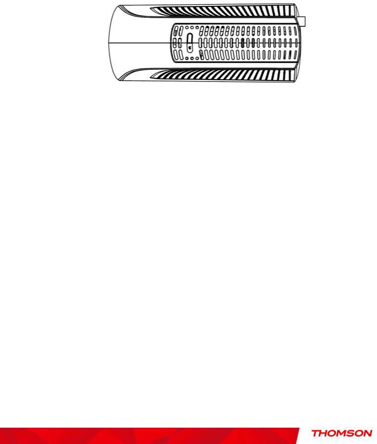
Wireless Voice Gateway Overview
Front Panel
The following illustration shows the front panel of the Wireless Voice Gateway:
8
Illustrations contained in this document are for representation only.

Chapter 1: Connections and Setup
The LEDs on the front panel are described in the table below (from left to right):
DWG875 / |
|
|
Internet |
|
|
Ethernet |
|
|
|
|
|
|
|
||
Power |
|
|
|
|
|
|
|
|
USB |
Wireless |
Tel 1 |
Tel 2 |
Battery |
Description |
|
DWG875T |
|
|
|
|
|
|
|
|
|||||||
|
DS |
US |
|
Online |
1 |
2 |
3 |
4 |
|
|
|
|
|
|
|
|
|
|
|
|
|
|
|
|
|||||||
|
|
|
|
|
|
|
|
|
|
|
|
|
|
|
|
|
ON |
ON |
ON |
|
ON |
ON |
ON |
ON |
ON |
On |
X |
ON |
ON |
X |
Power on 0.25 sec |
|
|
|
|
|
|
|
|
|
|
|
|
|
|
|
|
|
On |
0.25 second |
|
|
|
|
|
|
|
|
|
|
|||
Boot-up |
ON |
FLASH |
FLASH |
|
FLASH |
X |
X |
X |
X |
X |
X |
X |
X |
X |
From power ON to system |
|
|
|
|||||||||||||
Operation |
|
|
|
|
|
|
|
|
|
|
|
|
|
|
initialization complete |
|
|
|
|
|
|
|
|
|
|
|
|
|
|
|
|
|
|
ON |
ON |
|
ON |
|
|
|
|
|
|
|
|
|
Following system initialization |
|
ON |
|
|
|
|
X |
X |
X |
X |
X |
X |
X |
X |
X |
|
|
|
|
|
|
|
|
|
|
|
|
|
|
|
|
complete to (before) |
|
|
|
1 second |
|
|
|
|
|
|
|
|
|
|
||
|
|
|
|
|
|
|
|
|
|
|
|
|
|
||
|
ON |
FLASH |
OFF |
|
OFF |
X |
X |
X |
X |
X |
X |
X |
X |
X |
During DS scanning and |
|
|
|
|||||||||||||
|
|
|
|
|
|
|
|
|
|
|
|
|
|
|
acquiring SYNC |
|
|
|
|
|
|
|
|
|
|
|
|
|
|
|
|
|
|
|
|
|
|
|
|
|
|
|
|
|
|
|
From SYNC completed, |
|
ON |
ON |
FLASH |
|
OFF |
X |
X |
X |
X |
X |
X |
X |
X |
X |
receiving UCD to ranging |
|
|
|
|
|
|
|
|
|
|
|
|
|
|
|
|
DOCSIS Start-up |
|
|
|
|
|
|
|
|
|
|
|
|
|
|
completed |
Operation |
|
|
|
|
|
|
|
|
|
|
|
|
|
|
During DHCP, configuration file |
|
ON |
ON |
ON |
|
FLASH |
X |
X |
X |
X |
X |
X |
X |
X |
X |
download, registration, and |
|
|
|
|
|
|
|
|
|
|
|
|
|
|
|
|
|
|
|
|
|
|
|
|
|
|
|
|
|
|
|
Baseline Privacy initialization |
|
|
|
|
|
|
|
|
|
|
|
|
|
|
|
|
|
ON |
ON |
ON |
|
ON |
X |
X |
X |
X |
X |
X |
X |
X |
X |
Operational (NACO=ON) |
|
|
|
|
|
|
|
|
|
|
|
|
|
|
|
|
|
ON |
FLASH |
FLASH |
|
OFF |
X |
X |
X |
X |
X |
X |
X |
X |
X |
Operational (NACO=OFF) |
|
|
|
|
|
|
|
|
|
|
|
|
|
|
|
|
|
|
|
|
|
|
|
|
|
|
|
|
|
|
|
Wait registration with all DS |
|
FLASH |
FLASH |
FLASH |
|
FLASH |
FLASH |
X |
X |
X |
X |
X |
X |
X |
X |
and all US – Lights Flash |
|
|
|
|||||||||||||
|
|
|
|
|
|
|
|
|
|
|
|
|
|
|
sequentially from the right to |
|
|
|
|
|
|
|
|
|
|
|
|
|
|
|
left |
|
|
|
|
|
|
|
|
|
|
|
|
|
|
|
|
|
|
|
|
|
|
|
|
|
|
|
|
|
|
|
From 1 to 4 DS, from 1 to 4 |
Channel |
X |
X |
X |
|
X |
OFF |
X |
X |
X |
X |
X |
X |
X |
X |
LEDs are ON. |
|
|
||||||||||||||
|
|
|
|
|
|
|
|
|
|
|
|
|
|
|
|
Bonding |
|
|
|
|
|
|
|
|
|
|
|
|
|
|
From 5 to 8 DS, From 1 to 4 |
|
|
|
|
|
|
|
|
|
|
|
|
|
|
|
|
Operation |
|
|
|
|
|
|
|
|
|
|
|
|
|
|
LEDs are flashing |
|
|
|
|
|
|
|
|
|
|
|
|
|
|
|
|
|
|
|
|
|
|
|
|
|
|
|
|
|
|
From 1 to 4 US, from 1 to 4 |
|
|
|
|
|
|
|
|
|
|
|
|
|
|
|
|
|
|
OFF |
X |
X |
|
X |
X |
X |
X |
X |
X |
X |
X |
X |
X |
|
|
|
|
|
|
|
|
|
|
|
|
|
|
|
|
LEDs are ON. |
|
|
|
|
|
|
|
|
|
|
|
|
|
|
|
|
|
|
|
|
|
|
|
|
|
|
|
|
|
|
|
Wait registration with all DS |
|
FLASH |
FLASH |
FLASH |
|
FLASH |
FLASH |
X |
X |
X |
X |
X |
X |
X |
X |
and all US – Lights Flash |
|
|
|
|||||||||||||
|
|
|
|
|
|
|
|
|
|
|
|
|
|
|
sequentially from the left to |
|
|
|
|
|
|
|
|
|
|
|
|
|
|
|
right |
|
|
|
|
|
|
|
|
|
|
|
|
|
|
|
|
9
Illustrations contained in this document are for representation only.

Chapter 1: Connections and Setup
DWG875 / |
|
|
Internet |
|
|
Ethernet |
|
|
|
|
|
|
|
||
Power |
|
|
|
|
|
|
|
USB |
Wireless |
Tel 1 |
Tel 2 |
Battery |
Description |
||
DWG875T |
|
|
|
|
|
|
|
||||||||
|
DS |
US |
Online |
1 |
2 |
3 |
4 |
|
|
|
|
|
|
||
|
|
|
|
|
|
|
|
||||||||
|
|
|
|
|
|
|
|
|
|
|
|
|
|
|
|
MTA |
ON |
ON |
ON |
ON |
X |
X |
X |
X |
X |
X |
FLASH |
OFF |
OFF |
MTA DHCP |
|
initialization |
ON |
ON |
ON |
ON |
X |
X |
X |
X |
X |
X |
OFF |
FLASH |
OFF |
MTA SNMP/TFTP |
|
ON |
ON |
ON |
ON |
X |
X |
X |
X |
X |
X |
FLASH |
FLASH |
OFF |
RSIP for NCS/Register for SIP |
||
|
|||||||||||||||
|
|
|
|
|
OFF |
OFF |
OFF |
OFF |
|
|
|
|
|
No Ethernet Link |
|
|
ON |
X |
X |
X |
ON |
ON |
ON |
ON |
X |
X |
X |
X |
X |
Ethernet Link |
|
|
|
|
|
|
|
|
|
|
|
||||||
CPE Operation |
|
|
|
|
FLASH |
FLASH |
FLASH |
FLASH |
|
|
|
|
|
TX/RX Ethernet Traffic |
|
|
|
|
|
|
|
|
|
|
|
OFF |
|
|
|
Wireless is disable |
|
|
ON |
X |
X |
X |
X |
X |
X |
X |
X |
ON |
X |
X |
X |
Wireless initiate success or |
|
|
|
|
|
|
|
|
|
|
|
|
|
|
|||
|
|
|
|
|
|
|
|
|
|
FLASH |
|
|
|
TX/RX Wireless Traffic |
|
USB Operation |
|
|
|
|
|
|
|
|
OFF |
|
|
|
|
No USB Link |
|
ON |
X |
X |
X |
X |
X |
X |
X |
ON |
X |
X |
X |
X |
USB Link |
||
|
|
|
|
|
|
|
|
|
|
|
|
|
|||
|
|
|
|
|
|
|
|
|
FLASH |
|
|
|
|
TX/RX USB Traffic |
|
|
|
|
|
|
|
|
|
|
|
|
|
|
|
|
|
AC Good |
|
|
|
|
|
|
|
|
|
|
ON |
ON |
|
Both Lines On-Hook |
|
On |
|
|
< CM Normal Operation > |
|
|
|
FLASH |
ON |
ON |
Tel1 Off-hook, Tel2 On-hook |
|||||
|
|
|
|
|
|
||||||||||
Battery Good |
|
|
|
|
|
|
|
|
|
|
ON |
FLASH |
|
Tel1 On-hook, Tel2 Off-hook |
|
|
|
|
|
|
|
|
|
|
|
|
|
||||
|
|
|
|
|
|
|
|
|
|
<CM |
FLASH |
FLASH |
|
Both Lines Off-Hook |
|
AC Good |
|
|
|
|
|
|
|
|
|
Normal |
ON |
ON |
|
Both Lines On-Hook |
|
On |
|
|
< CM Normal Operation > |
|
|
FLASH |
ON |
FLASH |
Tel1 Off-hook, Tel2 On-hook |
||||||
|
|
|
|
|
|
||||||||||
Battery Low |
|
|
|
|
|
|
|
|
|
Operatio |
ON |
FLASH |
|
Tel1 On-hook, Tel2 Off-hook |
|
|
|
|
|
|
|
|
|
|
|
|
|
||||
|
|
|
|
|
|
|
|
|
|
n> |
FLASH |
FLASH |
|
Both Lines Off-Hook |
|
AC Good |
|
|
|
|
|
|
|
|
|
|
ON |
ON |
|
Both Lines On-Hook |
|
Flash |
|
|
< CM Normal Operation > |
|
|
|
FLASH |
ON |
OFF |
Tel1 Off-hook, Tel2 On-hook |
|||||
|
|
|
|
|
|
||||||||||
Battery Bad |
|
|
|
|
|
|
|
|
|
|
ON |
FLASH |
|
Tel1 On-hook, Tel2 Off-hook |
|
|
|
|
|
|
|
|
|
|
|
|
|
||||
|
|
|
|
|
|
|
|
|
|
|
FLASH |
FLASH |
|
Both Lines Off-Hook |
|
AC Fail |
|
|
|
|
|
|
|
|
|
|
ON |
|
|
Both Lines On-Hook |
|
|
|
|
|
|
|
|
|
|
|
|
FLASH |
|
OFF |
Tel1 Off-hook, Tel2 On-hook |
|
Battery Good |
|
|
|
|
|
|
|
|
|
|
ON |
|
|
Tel1 On-hook, Tel2 Off-hook |
|
|
Flash |
|
|
|
Off |
|
|
|
Off |
FLASH |
|
|
Both Lines Off-Hook |
||
AC Fail |
|
|
|
|
|
|
|
|
|
|
ON |
|
|
Both Lines On-Hook |
|
|
|
|
|
|
|
|
|
|
|
|
FLASH |
Off |
FLASH |
Tel1 Off-hook, Tel2 On-hook |
|
Battery Low |
|
|
|
|
|
|
|
|
|
|
ON |
|
|
Tel1 On-hook, Tel2 Off-hook |
|
|
|
|
|
|
|
|
|
|
|
|
FLASH |
|
|
Both Lines Off-Hook |
|
AC Fail |
|
|
|
|
|
|
|
|
|
|
|
|
|
Both Lines On-Hook |
|
|
|
|
< All LEDs may be unlit due to lack of battery power> |
|
|
|
OFF |
Tel1 Off-hook, Tel2 On-hook |
|||||||
Battery Bad |
|
|
|
|
|
|
|
|
|
|
|
|
|
Tel1 On-hook, Tel2 Off-hook |
|
|
|
|
|
|
|
|
|
|
|
|
|
|
|
Both Lines Off-Hook |
|
|
|
|
|
|
|
|
|
|
|
|
|
|
|
A software download and |
|
SW Download |
|
|
|
|
|
|
|
|
|
|
|
|
|
|
|
|
ON |
FLASH |
FLASH |
ON |
X |
X |
X |
X |
X |
X |
X |
X |
X |
while updating the FLASH |
|
Operation |
|
|
|
|
|
|
|
|
|
|
|
|
|
|
|
|
|
|
|
|
|
|
|
|
|
|
|
|
|
memory |
|
|
|
|
|
|
|
|
|
|
|
|
|
|
|
|
|
10
Illustrations contained in this document are for representation only.
Chapter 1: Connections and Setup
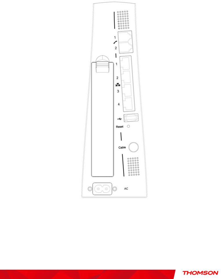
Rear Panel
A TEL1 & TEL2 |
2x Telephony RJ-11 connectors |
BETHERNET 1 2 3 4: 4x Ethernet 10/100/1000 Mbps RJ-45 connectors
C |
USB Host: |
1x |
USB 2.0 Connector |
D |
Reset: |
1x |
Reset or reset to factory default this Wireless Voice Gateway |
11
Illustrations contained in this document are for representation only.
Chapter 1: Connections and Setup
E |
CABLE: |
1x F-Connector for the coax cable |
F |
Power Connector: |
1x AC Power Connector |
IWPS & WiFi on/off button: 1x button with two features:
to activate/disable the WiFi, to execute a WPS association
12
Illustrations contained in this document are for representation only.
Chapter 1: Connections and Setup
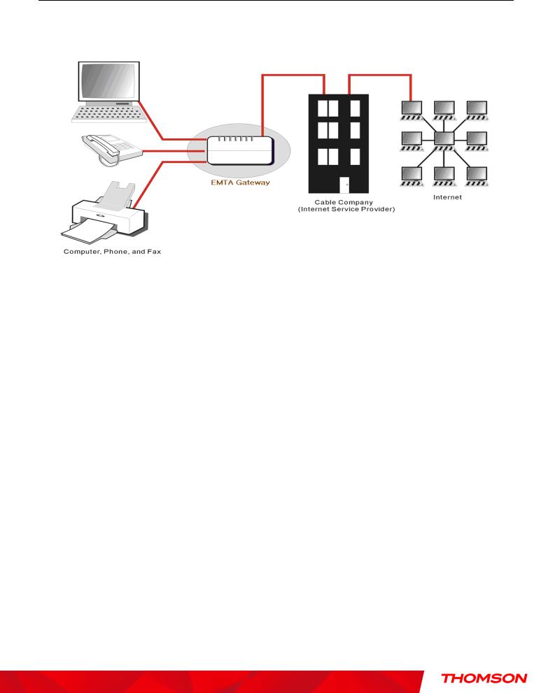
Relationship among the Devices
This illustration shows a cable company that offers DOCSIS and PacketCable-compliant voice/data services.
What the Modem Does
The Wireless Voice Gateway provides high-speed Internet access as well as cost-effective, toll-quality telephone voice and fax/modem services over residential, commercial, and education subscribers on public and private networks via an existing CATV infrastructure. It can inter-operate with the PacketCable compliant head-end equipment and provide the IP-based voice communications. The IP traffic can transfer between the Wireless Voice Gateway and DOCSIS compliant head-end equipment. The data security secures upstream and downstream communications.
13
Illustrations contained in this document are for representation only.

Chapter 1: Connections and Setup
What the Modem Needs to Do Its Job
The Right Cable Company: Make sure your local cable company provides data services that use cable TV industry-standard DOCSIS compliant and PacketCable compliant technology.
The Internet/Telephony Service Provider (ISP/TSP): Your cable company provides you access to an Internet Service Provider (ISP) and Telephony Service Provider (TSP). The ISP is your gateway to the Internet and provides you with a pipeline to access Internet content on the World Wide Web (WWW). The TSP provides you with telephony access to other modems or other telephony services over the Public Switched Telephone Network (PSTN).
Check with your cable company to make sure you have everything you need to begin; they’ll know if you need to install special software or re-configure your computer to make your cable internet service work for you.
14
Illustrations contained in this document are for representation only.

Chapter 1: Connections and Setup
Contact Your Local Cable Company
You will need to contact your cable company to establish an Internet account before you can use your gateway. You should have the following information ready (which you will find on the sticker on the gateway):
•The serial number
•The model number
•The Cable Modem (CM) Media Access Control (MAC) address
•The Terminal Adapter (EMTA) MAC address
•Security information: Service Set IDentifier (SSID), Encryption key / passphrase (WPA2-PSK by default), channel number. Default values are indicated underneath the modem on the sticker.
Please verify the following with the cable company
The cable service to your home supports DOCSIS compliant two-way modem access.
Your internet account has been set up. (The Media Terminal Adapter will provide data service if the cable account is set up but no telephony service is available.)
You have a cable outlet near your PC and it is ready for Cable Modem service.
Note: It is important to supply power to the modem at all times. Keeping your modem plugged in will keep it connected to the Internet. This means that it will always be ready whenever you need.
Important Information
Your cable company should always be consulted before installing a new cable outlet. Do not attempt any rewiring without contacting your cable company first.
15
Illustrations contained in this document are for representation only.
Chapter 1: Connections and Setup
Connecting the Wireless Voice Gateway to a Single Computer
This section of the manual explains how to connect your Wireless Voice Gateway to the USB or Ethernet port on your computer and install the necessary software. Please refer to Figure 1 to help you connect your Digital Cable Modem for the best possible connection.
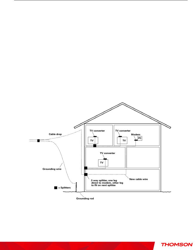
Attaching the Cable TV Wire to the Wireless Voice Gateway
1.Locate the Cable TV wire. You may find it one of three ways:
a.Connected directly to a TV, a Cable TV converter box, or VCR. The line will be connected to the jack, which should be labeled either IN, CABLE IN, CATV, CATV IN, etc.
b.Connected to a wall-mounted cable outlet.
c.Coming out from under a baseboard heater or other location. See Figure 1 for the wiring example.
Notes: For optimum performance, be sure to connect your Wireless Voice Gateway to the first point the cable enters your home. The splitter must be rated for at least 1GHz.
Fig. 1: Basic Home Wiring
16
Illustrations contained in this document are for representation only.
Chapter 1: Connections and Setup
Important Connection Information
The Wireless Voice Gateway supports Ethernet connection.
Below are important points to remember before you connect the Wireless Voice Gateway.
For Ethernet connections, go to page 21.
For telephone and fax connections, go to page 23.
If you do not want to use the CD-ROM, follow instructions 1 through 4 to connect the Wireless Voice Gateway to the Ethernet port on your computer. Instructions must be followed in the order they
appear.
1.Connect one end of the coaxial cable to the cable connection on the wall, and the other end to the CABLE jack on the Wireless Voice Gateway.
2.Attaching power cord to Wireless Voice Gateway and plug into the AC outlet.
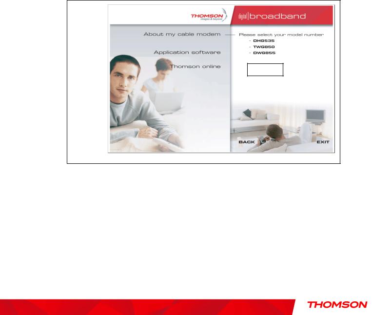
3.Insert the supplied Wireless Voice Gateway CD-ROM. Wait momentarily for the CD window display.
DWG875/D
Fig. 2: Main screen of CD
4. Close all open applications and dialog boxes, including the CD window.
Note: Some applications may interfere with your Wireless Voice Gateway installation.
17
Illustrations contained in this document are for representation only.
Chapter 1: Connections and Setup
Ethernet Connection to a Computer
Make the connection to the modem in the following sequence:
1.Connect one end of the coaxial cable to the cable connection on the wall, and the other end to the CABLE jack on the Wireless Voice Gateway.
2.Connect the plug from the AC power supply into the POWER AC ADAPTER jack on the Wireless Voice Gateway, and plug the power supply into an AC outlet.
Note: Use only the power supply that accompanied this unit. Using other adapters may damage the unit.
3.Connect one end of the Ethernet cable to an Ethernet port on the back of your computer, and the other end to the ETHERNET port on the Wireless Voice Gateway.
Fig.3: Ethernet Connection
18
Illustrations contained in this document are for representation only.
Chapter 1: Connections and Setup
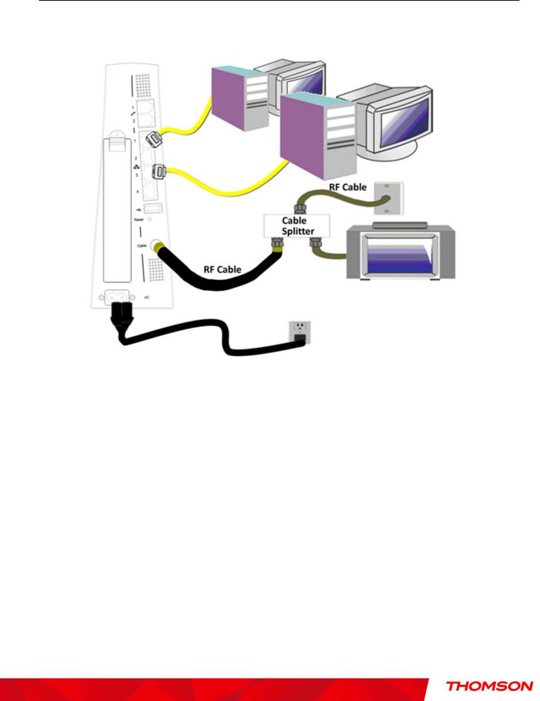
Connecting More Than A Computer to the Wireless Voice Gateway
If you need to connect more than one computer to the Wireless Voice Gateway, simply connect the computers to an Ethernet port on the rear panel.
Fig.4: Multiple-PC Connection
Note: You may need to check with your service provider in order to connect multiple computers.
19
Illustrations contained in this document are for representation only.
Chapter 1: Connections and Setup
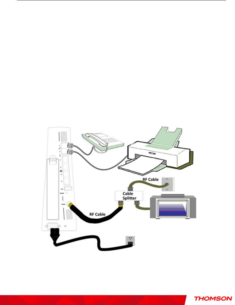
Telephone or Fax Connection
When properly connected, most telephony devices can be used with the Wireless Voice Gateway just as with a conventional telephone service. To make a normal telephone call, pick up the handset; listen for a dial tone, then dial the desired number. For services such as call waiting, use the hook switch (or FLASH button) to change calls. The following procedures describe some of the possible connection schemes for using telephony devices with the Wireless Voice Gateway.
1.Connect a standard phone line cord directly from the phone (fax machine, answering machine, caller ID box, etc.) to one of the LINE jacks on the Wireless Voice Gateway.
2.If there is a phone line in your home which is NOT connected to another telephone service provider, connect a standard phone line cord from a jack on this line to one of the LINE jacks of the Wireless Voice Gateway. Connect a standard phone line cord directly from the phone (fax machine, answering machine, caller ID box, etc.) to one of the other jacks in the house that uses that line.
3.If you have a multi-line telephone, connect a standard phone line cord (not an RJ-14 type line cord) from the phone to the LINE jacks on the Wireless Voice Gateway. (Other phones can be added to each line by using standard phone line splitters.
Fig. 5: Phone/Fax Connection
20
Illustrations contained in this document are for representation only.

Chapter 1: Connections and Setup
Turning on the Wireless Voice Gateway
After installing the Wireless Voice Gateway and turn it on for the first time (and each time the modem is reconnected to the power), it goes through several steps before it can be used. Each of these steps is represented by a different pattern of flashing lights on the front of the modem.
Note: All indicators flash once before the initialization sequence.
If both DS and US LEDs are flashing sequentially, it means the Wireless Voice Gateway is automatically updating its system software. Please wait for the lights to stop flashing. You cannot use your modem during this time. Do not remove the power supply, switch off (on/off switch) or reset the Wireless Voice Gateway during this process.
21
Illustrations contained in this document are for representation only.
Chapter 2: WEB Configuration
Chapter 2: WEB Configuration
To make sure that you can access the Internet successfully, please check the following first.
1.Make sure the connection (through Ethernet or USB) between the Wireless Voice Gateway and your computer is OK.
2.Make sure the TCP/IP protocol is set properly.
3.Subscribe to a Cable Company.
4.Make sure appropriate LEDs are turned on for normal operation as noted in the previous chapter.
Accessing the Web Configuration
The Wireless Voice Gateway offers local management capability through a built in HTTP server and a number of diagnostic and configuration web pages. You can configure the settings on the web page and apply them to the device.
Once your host PC is properly configured; please proceed as follows:
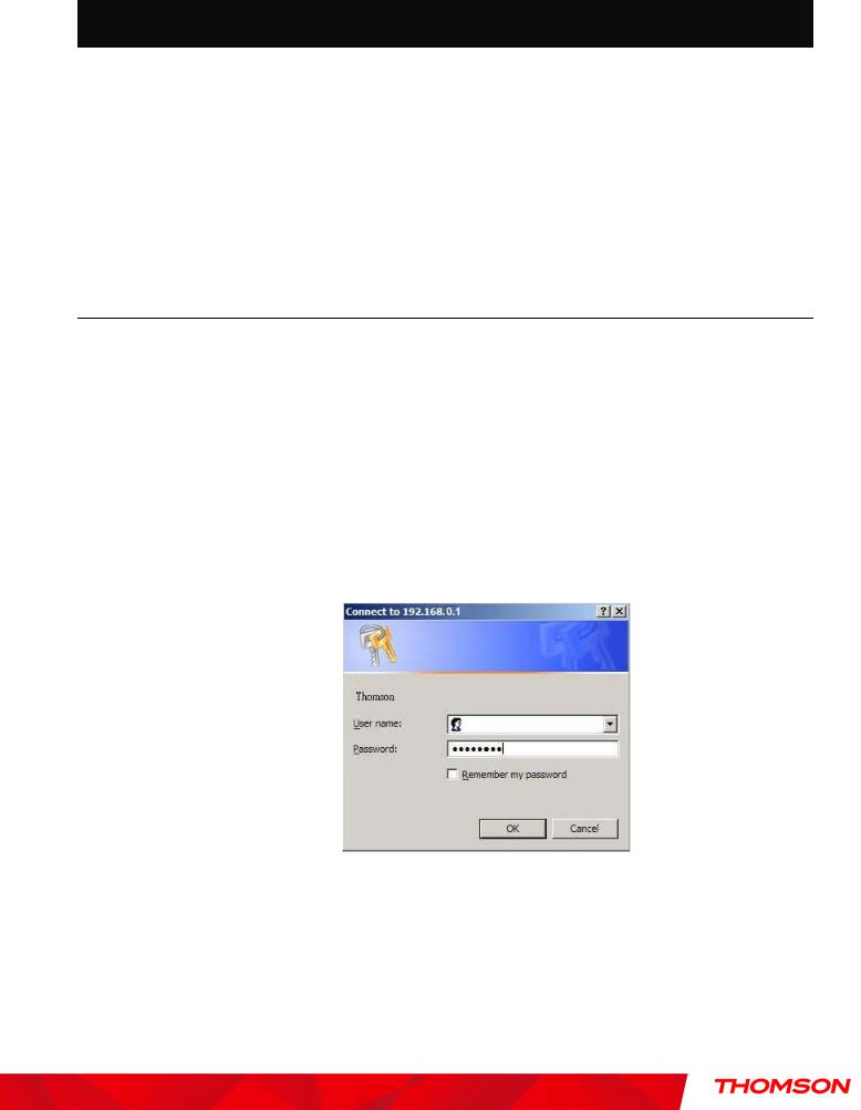
1.Start your web browser and type the private IP address of the Wireless Voice Gateway on the URL field: 192.168.0.1.
2.After connecting to the device, you will be prompted to enter username and password. By default, the username is “ ” (empty) and the password is “admin”.
Fig. 6 Dialogue for Login
If you login successfully, the main page will appear.
Please Note; some of the WEB pages shown later, will differ for different software versions and per service providers instructions.
22
Illustrations contained in this document are for representation only.

Chapter 2: WEB Configuration
Outline of Web Manager
The main screen will be shown as below.
Fig. 7 Outline of Web Manager
Main Menu: the hyperlinks on the top of the page, including Gateway, VoIP and several sub-menu items
Title: the sidebar on the left side of the page indicates the title of this management interface, e.g., Software in this example
Main Window: the current workspace of the web management, containing configuration or status information
For easy navigation, the pages are organized in groups with group in names main menu. Individual page names within each group are provided in the sidebar. So to navigate to a page, click the group hyperlink at the top, then the page title on the sidebar.
Your cable company may not support the reporting of some items of information listed on your gateway’s internal web pages. In such cases, the information field appears blank. This is normal.
23
Illustrations contained in this document are for representation only.

Chapter 2: WEB Configuration
Warning message to change the password
At your first connection or while the password is the default one, a warning message is displayed on the top banner of each Web configuration page. We want to encourage you to change the password in order to enforce the security of your modem. Please refer to the chapter “Password” page 27 for more information.
24
Illustrations contained in this document are for representation only.
 Loading...