

Page 1

eZ430-Chronos™ Development Tool
User's Guide
Literature Number: SLAU292F
November 2009–Revised October 2013
Page 2

Contents
Preface ....................................................................................................................................... 8
1 eZ430-Chronos™ Overview .................................................................................................. 9
1.1 Overview ..................................................................................................................... 9
1.2 eZ430-Chronos Features .................................................................................................. 9
1.3 Kit Contents ................................................................................................................ 10
2 Getting Started .................................................................................................................. 11
2.1 Using the eZ430-Chronos Wrist Module Stand Alone ................................................................ 11
2.1.1 Setting the Time .................................................................................................. 11
2.1.2 Setting the Date .................................................................................................. 12
2.1.3 Feature Overview and Menu Structure ........................................................................ 13
2.2 Install Demo Application, Drivers and Firmware ...................................................................... 14
2.2.1 Windows® Installation ........................................................................................... 14
2.2.2 Linux® Installation ................................................................................................ 14
2.3 Using the eZ430-Chronos Wrist Module With a PC .................................................................. 15
2.3.1 Transmission of Acceleration Data and Button Pushes ..................................................... 15
3 eZ430-Chronos Software .................................................................................................... 18
3.1 Overview .................................................................................................................... 18
3.2 eZ430-Chronos Demo Software ......................................................................................... 18
3.2.1 Detailed Feature Overview - Modes Using the Top LCD Line ............................................. 20
3.2.2 Detailed Feature Overview - Modes Using the Bottom LCD Line .......................................... 23
3.3 eZ430-Chronos Control Center PC Software .......................................................................... 26
3.3.1 SimpliciTI™ Acc/PPT Tab (Mouse and PowerPoint Control) ............................................... 27
3.3.2 Key Configuration Tab ........................................................................................... 30
3.3.3 SimpliciTI™ Sync ................................................................................................. 31
3.3.4 BlueRobin™ Heart Rate Simulator ............................................................................. 32
3.3.5 Wireless Update .................................................................................................. 33
3.4 eZ430-Chronos Data Logger ............................................................................................ 35
3.4.1 Detailed Feature Overview ...................................................................................... 36
3.5 Data Logger PC Software ................................................................................................ 36
3.5.1 SimpliciTI Data Logger ........................................................................................... 37
3.5.2 Wireless Update .................................................................................................. 39
3.6 eZ430-Chronos Software Projects ...................................................................................... 40
3.6.1 IDE Installation .................................................................................................... 40
3.6.2 eZ430-Chronos Software Flow ................................................................................. 41
3.6.3 eZ430-Chronos Wireless Update Feature .................................................................... 43
3.6.4 eZ430-Chronos Firmware ....................................................................................... 49
3.6.5 eZ430-Chronos GUI Sources ................................................................................... 50
4 eZ430-Chronos Hardware ................................................................................................... 56
4.1 Programming the eZ430-Chronos Wrist Module: Disassembly and Assembly of the Housing ................. 56
4.1.1 Disassembly of eZ430-Chronos Wrist Module ............................................................... 56
4.1.2 Assembly of eZ430-Chronos Wrist Module ................................................................... 58
4.2 Functional Description of the eZ430-Chronos Wrist Module ........................................................ 60
4.3 Functional Description of the eZ430-Chronos RF Access Point .................................................... 62
4.3.1 Access Point With Black PCB .................................................................................. 62
2
Contents SLAU292F–November 2009–Revised October 2013
Copyright © 2009–2013, Texas Instruments Incorporated
Submit Documentation Feedback
Page 3

www.ti.com
4.3.2 Access Point With White PCB .................................................................................. 63
4.4 Functional Description of the eZ430-Chronos Debug Interface ..................................................... 64
4.4.1 MSP430 Application UART ..................................................................................... 64
4.5 Schematics, Layout, BOM, and LCD ................................................................................... 65
4.5.1 eZ430-Chronos-433 Wrist Module With Black PCB ......................................................... 65
4.5.2 eZ430-Chronos-433 Wrist Module With White PCB ......................................................... 73
4.5.3 eZ430-Chronos-868 and -915 Wrist Modules With Black PCB ............................................ 81
4.5.4 eZ430-Chronos-868 and -915 Wrist Modules With White PCB ............................................ 89
4.5.5 LCD ................................................................................................................. 93
4.6 Access Point Schematics, Layout, and BOM .......................................................................... 95
4.6.1 eZ430-Chronos-433 With Black PCB RF Access Point ..................................................... 95
4.6.2 eZ430-Chronos-433 With White PCB RF Access Point ................................................... 100
4.6.3 eZ430-Chronos-868 and -915 With Black PCB RF Access Point ........................................ 105
4.6.4 eZ430-Chronos-868 and -915 With White PCB RF Access Point ........................................ 111
4.6.5 Debugging Interface Schematics and Layout ............................................................... 120
A Frequently Asked Questions ............................................................................................. 123
A.1 FAQs ....................................................................................................................... 123
B Detailed Hardware Driver Installation Guide ........................................................................ 126
B.1 eZ430-Chronos RF Access Point ...................................................................................... 126
B.2 eZ430-RF Debug Interface ............................................................................................. 130
Revision History ....................................................................................................................... 132
SLAU292F–November 2009–Revised October 2013 Contents
Submit Documentation Feedback
Copyright © 2009–2013, Texas Instruments Incorporated
3
Page 4

www.ti.com
List of Figures
1-1. eZ430-Chronos With Black PCB ........................................................................................ 10
1-2. eZ430-Chronos With White PCB........................................................................................ 10
2-1. eZ430-Chronos Wrist Module Push Buttons........................................................................... 11
2-2. Overview eZ430-Chronos LCD .......................................................................................... 11
2-3. eZ430-Chronos Feature Overview and Menu Structure ............................................................. 13
2-4. eZ430-Chronos Control Center.......................................................................................... 15
2-5. eZ430-Chronos Control Center With Acceleration Data ............................................................. 16
3-1. eZ430-Chronos Feature Overview and Menu Structure ............................................................. 19
3-2. eZ430-Chronos Control Center.......................................................................................... 27
3-3. eZ430-Chronos Control Center With Acceleration Data ............................................................. 28
3-4. eZ430-Chronos Control Center With PPT Control .................................................................... 29
3-5. eZ430-Chronos Control Center Key Configuration ................................................................... 30
3-6. eZ430-Chronos Control Center Sync................................................................................... 31
3-7. eZ430-Chronos Control Center Heart Rate Simulator................................................................ 32
3-8. eZ430-Chronos Control Center Wireless Update ..................................................................... 34
3-9. eZ430-Chronos Data Logger Feature Overview and Menu Structure.............................................. 35
3-10. eZ430-Chronos Data Logger ............................................................................................ 38
3-11. eZ430-Chronos Control Center Wireless Update..................................................................... 40
3-12. eZ430-Chronos Software Flowchart .................................................................................... 42
3-13. Flow Chart of Wireless Update Software on Access Point .......................................................... 44
3-14. Flow Chart of Flash Based Wireless Update Software on eZ430-Chronos Wrist Module....................... 45
3-15. Upgrade AP Firmware .................................................................................................... 46
3-16. eZ430-Chronos RF Access Point Connection to CC Debugger .................................................... 47
3-17. SmartRF Flash Programmer............................................................................................. 48
4-1. Remove Chronos Module From Housing .............................................................................. 56
4-2. Remove Chronos Module Battery....................................................................................... 57
4-3. eZ430-Chronos Module Attached to eZ430-RF Debug Interface................................................... 58
4-4. eZ430-Chronos Module Insertion Into Housing ....................................................................... 59
4-5. Metal Strips of Chronos Module Housing and Buttons of Housing ................................................. 59
4-6. Push Metal Strips Inward................................................................................................. 60
4-7. eZ430-Chronos Wrist Module Block Diagram ......................................................................... 60
4-8. eZ430-Chronos Module Front ........................................................................................... 61
4-9. eZ430-Chronos Module Back............................................................................................ 61
4-10. eZ430-Chronos RF Access Point ....................................................................................... 62
4-11. eZ430-Chronos RF Access Point Connection to CC Debugger .................................................... 62
4-12. Access Point With White PCB ........................................................................................... 63
4-13. Access Point With Connector............................................................................................ 63
4-14. eZ430-Chronos Debug Interface ........................................................................................ 64
4-15. eZ430-Chronos-433 Wrist Module With Black PCB, Schematics................................................... 65
4-16. eZ430-Chronos-433 Wrist Module With Black PCB, PCB Components on Top Layer .......................... 66
4-17. eZ430-Chronos-433 Wrist Module With Black PCB, Layout Top Layer (LCD Side) ............................. 67
4-18. eZ430-Chronos-433 Wrist Module With Black PCB, Layout Second Layer....................................... 68
4-19. eZ430-Chronos-433 Wrist Module With Black PCB, Layout Third Layer.......................................... 69
4-20. eZ430-Chronos-433 Wrist Module With Black PCB, Layout Bottom Layer (Battery Side) ...................... 70
4-21. eZ430-Chronos-433 Wrist Module With White PCB, Schematics .................................................. 73
4-22. eZ430-Chronos-433 Wrist Module With White PCB, PCB Components on Top Layer.......................... 74
4-23. eZ430-Chronos-433 Wrist Module With White PCB, Layout Top Layer (LCD Side) ............................. 75
4
List of Figures SLAU292F–November 2009–Revised October 2013
Copyright © 2009–2013, Texas Instruments Incorporated
Submit Documentation Feedback
Page 5

www.ti.com
4-24. eZ430-Chronos-433 Wrist Module With White PCB, Layout Second Layer....................................... 76
4-25. eZ430-Chronos-433 Wrist Module With White PCB, Layout Third Layer.......................................... 77
4-26. eZ430-Chronos-433 Wrist Module With White PCB, Layout Bottom Layer (Battery Side) ...................... 78
4-27. eZ430-Chronos-868 and -915 Wrist Modules With Black PCBs, Schematics..................................... 81
4-28. eZ430-Chronos-868 and -915 Wrist Modules With Black PCBs, PCB Components on Top Layer............ 82
4-29. eZ430-Chronos-868 and -915 Wrist Modules With Black PCBs, Layout Top Layer (LCD Side) ............... 83
4-30. eZ430-Chronos-868 and -915 Wrist Modules With Black PCBs, Layout Second Layer......................... 84
4-31. eZ430-Chronos-868 and -915 Wrist Modules With Black PCBs, Layout Third Layer............................ 85
4-32. eZ430-Chronos-868 and -915 Wrist Modules With Black PCBs, Layout Bottom Layer (Battery Side) ........ 86
4-33. eZ430-Chronos-868 Wrist Modules With White PCBs, Schematics................................................ 89
4-34. eZ430-Chronos-915 Wrist Modules With White PCBs, Schematics................................................ 90
4-35. LCD Segment Map........................................................................................................ 93
4-36. LCD Pinout ................................................................................................................. 94
4-37. eZ430-Chronos-433 RF Access Point With Black PCB, Schematics .............................................. 95
4-38. eZ430-Chronos-433 RF Access Point With Black PCB, PCB Components on Top Layer...................... 96
4-39. eZ430-Chronos-433 RF Access Point With Black PCB, Layout Top Layer ....................................... 97
4-40. eZ430-Chronos-433 RF Access Point With Black PCB, Layout Bottom Layer ................................... 98
4-41. eZ430-Chronos-433 RF Access Point With White PCB, Schematics............................................. 100
4-42. eZ430-Chronos-433 RF Access Point With White PCB, PCB Components on Top Layer .................... 101
4-43. eZ430-Chronos-433 RF Access Point With White PCB, Layout Top Layer...................................... 102
4-44. eZ430-Chronos-433 RF Access Point With White PCB, Layout Bottom Layer.................................. 103
4-45. eZ430-Chronos-868 and -915 RF Access Point With Black PCB, Schematics ................................. 105
4-46. eZ430-Chronos-868 and -915 RF Access Point With Black PCB, PCB Components on Top Layer......... 106
4-47. eZ430-Chronos-868 and -915 RF Access Point With Black PCB, Layout Top Layer .......................... 107
4-48. eZ430-Chronos-868 and -915 RF Access Point With Black PCB, Layout Bottom Layer ...................... 108
4-49. eZ430-Chronos-868 RF Access Point With White PCB, Schematics............................................. 111
4-50. eZ430-Chronos-915 RF Access Point With White PCB, Schematics............................................. 112
4-51. eZ430-Chronos-868 and -915 RF Access Point With White PCB, PCB Components on Top Layer......... 113
4-52. eZ430-Chronos-868 RF Access Point With White PCB, Layout Top Layer...................................... 114
4-53. eZ430-Chronos-915 RF Access Point With White PCB, Layout Top Layer...................................... 115
4-54. eZ430-Chronos-868 RF Access Point With White PCB, Layout Bottom Layer.................................. 116
4-55. eZ430-Chronos-915 RF Access Point With White PCB, Layout Bottom Layer.................................. 117
4-56. USB Debug Interface, Schematic...................................................................................... 120
4-57. USB Debug Interface, Schematic...................................................................................... 121
4-58. USB Debug Interface, PCB Components on Top Layer............................................................ 122
4-59. USB Debug Interface, PCB Components on Bottom Layer........................................................ 122
4-60. USB Debug Interface, Layout Top Layer ............................................................................. 122
4-61. USB Debug Interface, Layout Bottom Layer ......................................................................... 122
B-1. Device Driver installation Wizard for the Access Point ............................................................. 126
B-2. Successful Driver Installation for Access Point ...................................................................... 127
B-3. Access Point Detection for eZ430-Chronos With Black PCB ...................................................... 127
B-4. Access Point Detection for eZ430-Chronos With White PCB...................................................... 127
B-5. Windows Found New Hardware Wizard .............................................................................. 128
B-6. Automatic Driver installation............................................................................................ 128
B-7. Windows Uncertified Driver Installation Warning .................................................................... 129
B-8. Access Point in Windows Device Manager for eZ430-Chronos With Black PCB .............................. 129
B-9. Access Point in Windows Device Manager for eZ430-Chronos With White PCB .............................. 129
B-10. Port Settings for eZ430-Chronos With Black PCB .................................................................. 129
B-11. Port Settings for eZ430-Chronos With White PCB .................................................................. 129
SLAU292F–November 2009–Revised October 2013 List of Figures
Submit Documentation Feedback
Copyright © 2009–2013, Texas Instruments Incorporated
5
Page 6

www.ti.com
B-12. eZ430-RF Windows Driver Installation................................................................................ 130
B-13. eZ430-RF in Windows Device Manager as HID and COM Port Devices ........................................ 131
6
List of Figures SLAU292F–November 2009–Revised October 2013
Copyright © 2009–2013, Texas Instruments Incorporated
Submit Documentation Feedback
Page 7

www.ti.com
4-1. Estimated Battery Life (Demo Software) ............................................................................... 61
4-2. eZ430-Chronos-433 Wrist Module With Black PCB, BOM List...................................................... 71
4-3. eZ430-Chronos-433 Wrist Module With White PCB, BOM List ..................................................... 79
4-4. eZ430-Chronos-868 and -915 Wrist Modules With Black PCBs, BOM List ....................................... 87
4-5. eZ430-Chronos-868 and -915 PCB Cross Reference................................................................ 91
4-6. eZ430-Chronos-868 Wrist Module With White PCB, BOM List ..................................................... 91
4-7. eZ430-Chronos-433 Access Point With Black PCB, BOM List...................................................... 99
4-8. eZ430-Chronos-433 Access Point With White PCB, BOM List.................................................... 104
4-9. eZ430-Chronos-868 Access Point With Black PCB, BOM List .................................................... 109
4-10. eZ430-Chronos-915 Access Point With Black PCB, BOM List .................................................... 110
4-11. eZ430-Chronos-868 Access Point With White PCB, BOM List.................................................... 118
4-12. eZ430-Chronos-915 Access Point With White PCB, BOM List.................................................... 119
List of Tables
SLAU292F–November 2009–Revised October 2013 List of Tables
Submit Documentation Feedback
Copyright © 2009–2013, Texas Instruments Incorporated
7
Page 8

If You Need Assistance
If you have any feedback or questions, support for the MSP430™ microcontrollers and the eZ430Chronos™ software development tool is provided by the Texas Instruments Product Information Center
(PIC) (support.ti.com), the TI E2E Forum (http://e2e.ti.com/support/microcontrollers/msp430/default.aspx),
and the eZ430-Chronos wiki (www.ti.com/chronoswiki). Additional device-specific information can be found
on the MSP430 web site (www.ti.com/msp430).
Related Documentation from Texas Instruments
The primary sources of MSP430 information are the device-specific data sheets and user's guides. The
most up-to-date versions of the user's guide documents available at the time of production have been
provided on the CD-ROM included with this tool. However, the most current information is found at
www.ti.com/msp430.
Information specific to the eZ430-Chronos development tool can be found at www.ti.com/chronos.
MSP430 device and IDE user's guides may be accessed on the included CD-ROM under the user's
guides section. The IDE user's guides include detailed information on setting up a project for the MSP430
using Code Composer Studio™ integrated development environment (IDE) (SLAU157) and the IAR
Embedded Workbench™ IDE (SLAU138).
Preface
SLAU292F–November 2009–Revised October 2013
Read This First
FCC, IC, and Other Geographical Radio Use Restrictions
eZ430-Chronos-433 and eZ430-Chronos-868 are restricted from use in the USA and Canada due to
frequency conflicts.
eZ430-Chronos-915 is restricted from the use in Europe due to frequency conflicts.
It is the user's responsibility to assure this evaluation module is not operated in any other geographical
regions that may be restricted.
Environmental Operating Conditions
Operating temperature 0°C to 40°C (32°F to 104°F)
Storage temperature -20°C to 60°C (-4°F to 140°F)
Export Control Regulations
This development kit is subject to the export and import control regulations of the United States per the
harmonization code: ECCN 5A002A1A TSPA. Note that it may also be subject to export control policies of
local authorities.
Patents
German utility model and patent pending.
SimpliciTI, MSP430, eZ430-Chronos, Code Composer Studio are trademarks of Texas Instruments.
BlueRobin is a trademark of BM innovations GmbH.
IAR Embedded Workbench, KickStart are trademarks of IAR Systems.
Linux is a registered trademark of Linus Torvalds.
Windows, PowerPoint are registered trademarks of Microsoft Corporation.
All other trademarks are the property of their respective owners.
8
Read This First SLAU292F–November 2009–Revised October 2013
Copyright © 2009–2013, Texas Instruments Incorporated
Submit Documentation Feedback
Page 9

1.1 Overview
The eZ430-Chronos software development tool is a highly integrated, wearable, wireless development
system that is based on the CC430F6137. It may be used as a reference platform for watch systems, a
personal display for personal area networks, or as a wireless sensor node for remote data collection.
Based on the CC430F6137 sub-1-GHz RF SoC, the eZ430-Chronos is a complete development system
featuring a 96-segment LCD display, an integrated pressure sensor, and a three-axis accelerometer for
motion sensitive control. The integrated wireless interface allows the eZ430-Chronos to act as a central
hub for nearby wireless sensors such as pedometers and heart-rate monitors. The eZ430-Chronos offers
temperature and battery voltage measurement and is complete with a USB-based MSP430F5509 +
CC1101 (part of the new eZ430-Chronos kit with white PCBs) or CC1111 (part of the initial eZ430Chronos kit with black PCBs) wireless interface to a PC.
The eZ430-Chronos wrist module may be disassembled to be programmed with custom applications and
includes an eZ430 USB programming interface.
NOTE: The information provided in this document applies equally to all of the kits that are available,
Chapter 1
SLAU292F–November 2009–Revised October 2013
eZ430-Chronos™ Overview
unless otherwise noted.
There are several different eZ430-Chronos kit versions available. In addition to the different
frequency versions, there are two generations of kits:
• First generation eZ430-Chronos with black PCBs (legacy), sometimes referred
to as "Chronos BLACK"
– Chronos module based on VIT accelerometer and pressure sensor
– Chronos module based on discrete RF matching
– Access Point based on CC1111 (8051 based SoC with USB and <1GHz
transceiver)
• Second generation eZ430-Chronos with white PCBs, sometimes referred to as
"Chronos WHITE"
– Chronos module based on Bosch Sensortec accelerometer and pressure
sensor
– Model number engraved in metal back of wrist housing
– Chronos module based on Johanson Technology Filter baluns
– Access Point based on MSP430F5509 microcontroller with USB and
CC1101 <1GHz transceiver
1.2 eZ430-Chronos Features
• Sports watch development kit based on the CC430F6137, an MSP430™ microcontroller with
integrated sub-1-GHz wireless transceiver
• Wrist module can be programmed for custom wireless applications
• Highly integrated wrist module includes on-board three-axis accelerometer, pressure sensor,
temperature sensor, and battery voltage sensor
• 96-segment LCD display driven directly by the CC430 microcontroller
• Can be paired wirelessly with heart-rate monitors, pedometers, or other devices based on RF
SLAU292F–November 2009–Revised October 2013 eZ430-Chronos™ Overview
Submit Documentation Feedback
Copyright © 2009–2013, Texas Instruments Incorporated
9
Page 10

Kit Contents
transceivers such as the CC430 or CC11xx devices
• Includes an eZ430-RF USB emulator that connects the eZ430-Chronos to a PC for real-time in-system
programming and debugging.
Figure 1-1. eZ430-Chronos With Black PCB Figure 1-2. eZ430-Chronos With White PCB
1.3 Kit Contents
• One eZ430-Chronos module with wrist housing (battery included)
• One eZ430-RF USB debugging interface
• One CC1111 USB RF access point (Chronos BLACK only)
• One MSP430F5509 + CC1101 USB RF access point (Chronos WHITE only)
• One 4-pin solder-on debug connector for the USB RF access point (Chronos WHITE only)
• One mini Phillips screwdriver
• Two spare screws
• One MSP430 development tool CD containing documentation and development software (Chronos
BLACK only)
– eZ430-Chronos™ Windows® PC-Software and Source Code SLAC341
– eZ430-Chronos™ Linux® PC-Software and Source Code SLAC388
– eZ430-Chronos™ Development Tool User's Guide SLAU292
– CC430 Family User's Guide SLAU259
– Code Composer Studio™ v5 CCS Mediawiki
– Code Composer Studio™ v5 User's Guide for MSP430 SLAU157
– IAR Embedded Workbench™ KickStart™ SLAC050
– IAR Embedded Workbench™ User's Guide for MSP430 SLAU138
www.ti.com
10
NOTE: For the latest software and documentation, go to www.ti.com/chronos or
www.ti.com/chronoswiki.
eZ430-Chronos™ Overview SLAU292F–November 2009–Revised October 2013
Copyright © 2009–2013, Texas Instruments Incorporated
Submit Documentation Feedback
Page 11
SLAU292F–November 2009–Revised October 2013
2.1 Using the eZ430-Chronos Wrist Module Stand Alone
For first time use, remove the eZ430-Chronos from box and press any button twice to wake the Chronos
module from sleep mode. After the first button press, the LCD displays the same content as shown on the
box of the kit, and after the second button press, the Chronos module starts full operation.
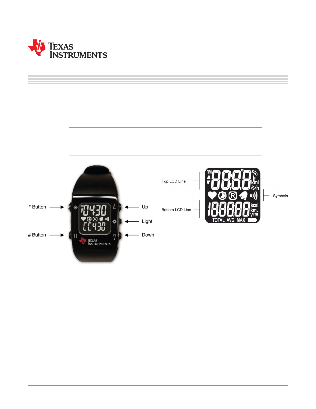
NOTE: For the next steps it is important to understand the eZ430-Chronos user concept. The top
and bottom LCD lines can be controlled individually by pushing the buttons on the left side.
The buttons on the right side are used to select or activate secondary functions. Detailed
instructions are available in Section 3.2.
Chapter 2
Getting Started
Figure 2-1. eZ430-Chronos Wrist Module Push
Buttons
2.1.1 Setting the Time
1. Push the * button until the time is displayed in the top LCD line.
2. Hold * for three seconds until the time disappears and 12H or 24H is shown on the LCD.
3. Select 12H or 24H mode by pushing the UP or DOWN buttons.
4. Press # to continue with the time adjustment.
5. Set the hours by pushing the UP or DOWN button.
6. Press # to continue with the minute adjustment.
7. Set the minutes by pushing the UP or DOWN button.
8. Press # to continue with the second adjustment.
9. Set the seconds by pushing the UP or DOWN button.
10. Press * to confirm the settings and go back to normal operation, or press # to start over with step 2.
Figure 2-2. Overview eZ430-Chronos LCD
SLAU292F–November 2009–Revised October 2013 Getting Started
Submit Documentation Feedback
Copyright © 2009–2013, Texas Instruments Incorporated
11
Page 12

Using the eZ430-Chronos Wrist Module Stand Alone
NOTE: If no button is pushed for more than 30 seconds, the previous settings are restored.
Alternatively, the time and date may be set wirelessly using the eZ430-Chronos Control
Center (see Section 3.3.3).
2.1.2 Setting the Date
1. Push the # button until the date is displayed in the bottom LCD line.
2. Hold # for three seconds until the year flashes on the bottom LCD line.
3. Set the year by pushing the UP or DOWN button.
4. Press # to continue with the month adjustment.
5. Set the month by pushing the UP or DOWN button.
6. Press # to continue with the day adjustment.
7. Set the day by pushing the UP or DOWN button.
8. Press * to confirm the settings and go back to normal operation, or press # to start over with step 3.
NOTE: If no button is pushed for more than 30 seconds, the previous settings are being restored.
www.ti.com
12
Getting Started SLAU292F–November 2009–Revised October 2013
Copyright © 2009–2013, Texas Instruments Incorporated
Submit Documentation Feedback
Page 13

Top Modes
Bottom Modes
* button for
mode selection
UP button for
alternate functions
# button for
mode selection
DOWN button for
alternate functions
Seconds
HR
On or Off
ACC
On or Off
Year
Start or
Stop
Hold * button for
set functions
Set
Time
Calibrate
Altitude
Tilt
Z-Axis
Tilt
X-Axis
Alarm
On or Off
Time
Alarm
Temp
Heart
Rate
Altitude
Speed
Tilt
Y-Axis
Date
Stop
watch
Battery
PPTACC SYNC Calories
Set
Alarm
Calibrate
Temp
To modify values in set functions, press UP or DOWN to select values, # for the next item, and * to save.
RFBSL
SYNC
On or Off
Distance
Start
Update
PPT
On or Off
Set
Date
To modify values in set functions, press UP or DOWN to select values, # for the next item, and * to save.
Reset
to Zero
Calorie
Settings
Hold # button for
set functions
www.ti.com
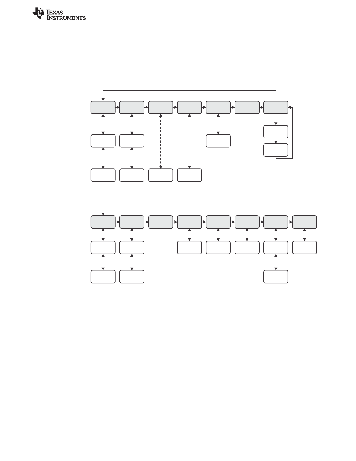
2.1.3 Feature Overview and Menu Structure
Figure 2-3 shows all modes and secondary functions. A detailed description of the features can be found
in Section 3.2.
Using the eZ430-Chronos Wrist Module Stand Alone
Figure 2-3. eZ430-Chronos Feature Overview and Menu Structure
SLAU292F–November 2009–Revised October 2013 Getting Started
Submit Documentation Feedback
Copyright © 2009–2013, Texas Instruments Incorporated
13
Page 14

Install Demo Application, Drivers and Firmware
2.2 Install Demo Application, Drivers and Firmware
The eZ430-Chronos PC software supports Windows®and Linux®(Ubuntu 12.04) operating systems.
Download the latest eZ430-Chronos Software and Source Code Installer for Windows (SLAC341) or for
Linux (SLAC388) from the eZ430-Chronos web page at www.ti.com/chronos.
2.2.1 Windows® Installation
1. Unzip the archive and run Chronos-Setup.exe.
2. Respond to the prompts to install the software. During the installation a separate window opens for the
Windows driver installation. Accept the driver installation.
NOTE: The eZ430-Chronos access point driver may not be certified by Microsoft. Therefore,
Windows may generate a warning. Allow the driver installation to continue.
3. When installation finishes, connect the eZ430-Chronos RF USB access point to the PC and follow the
Windows driver installation (see Section 2.3).
4. If prompted for the driver for the TI CC1111 Low-Power RF to USB CDC Serial Port (legacy software),
or eZ430-ChronosAP (current software) allow Windows to 'Install the software automatically'. This can
be done only if the eZ430-Chronos PC Software package has already been installed.
5. Open the eZ430-Chronos Control Center program. A shortcut is available on the Desktop and the Start
Menu under Programs > Texas Instruments > eZ430-Chronos > eZ430-Chronos Control Center.
For a detailed driver installation, see Appendix B.
www.ti.com
2.2.2 Linux® Installation
The eZ430-Chronos PC software for Linux requires TCL/Tk. If the Linux distribution does not already
include TCL/Tk yet, install both with the apt-get command:
sudo apt-get install tcl8.5-dev
sudo apt-get install tk8.5-dev
To generate keyboard events and mouse clicks through the Chronos module buttons, xdotool is required.
Install with the apt-get command:
sudo apt-get install xdotool
The PC now has the infrastructure for the eZ430-Chronos PC Software. Continue with the eZ430-Chronos
installation:
1. Extract the archive and run Chronos-Setup.
2. Respond to the prompts to install the software.
3. Insert the eZ430-Chronos RF USB access point to the PC.
4. Check the /dev directory for new entry /dev/ttyACMx, where x specifies the number of the port.
5. Set the COM variable in eZ430-Chronos_CC_1_2.tcl and eZ430-Chronos_Datalogger_1_2.tcl if the
USB RF access point is not mounted as /dev/ttyACM0
6. Set script files to executable:
chmod u+x ./eZ430-Chronos_CC_1_2.tcl
chmod u+x ./eZ430-Chronos_Datalogger_1_2.tcl
7. Launch the script (./eZ430-Chronos_CC_1_2.tcl) from terminal as root user.
NOTE: Linux is supported by the eZ430-Chronos Control Center and eZ430-Chronos Data Logger
PC applications. The eZ430-Chronos software package also contains all source code for the
Chronos module and access point, which are provided for Code Composer Studio IDE
(Windows and Linux) and the IAR Embedded Workbench IDE (Windows only). CrossWorks
from Rowley Associates supports Linux and MacOS in addition to Windows OS but requires
manual project setup. MSPGCC may also be used.
14
Getting Started SLAU292F–November 2009–Revised October 2013
Copyright © 2009–2013, Texas Instruments Incorporated
Submit Documentation Feedback
Page 15
www.ti.com
2.3 Using the eZ430-Chronos Wrist Module With a PC
1. The Control Center provides a variety of demos. A detailed description can be found in Section 3.3.
The following sections describe only how to use the eZ430-Chronos module to control the mouse
pointer on the PC and to use it to control PowerPoint®presentation software.
Using the eZ430-Chronos Wrist Module With a PC
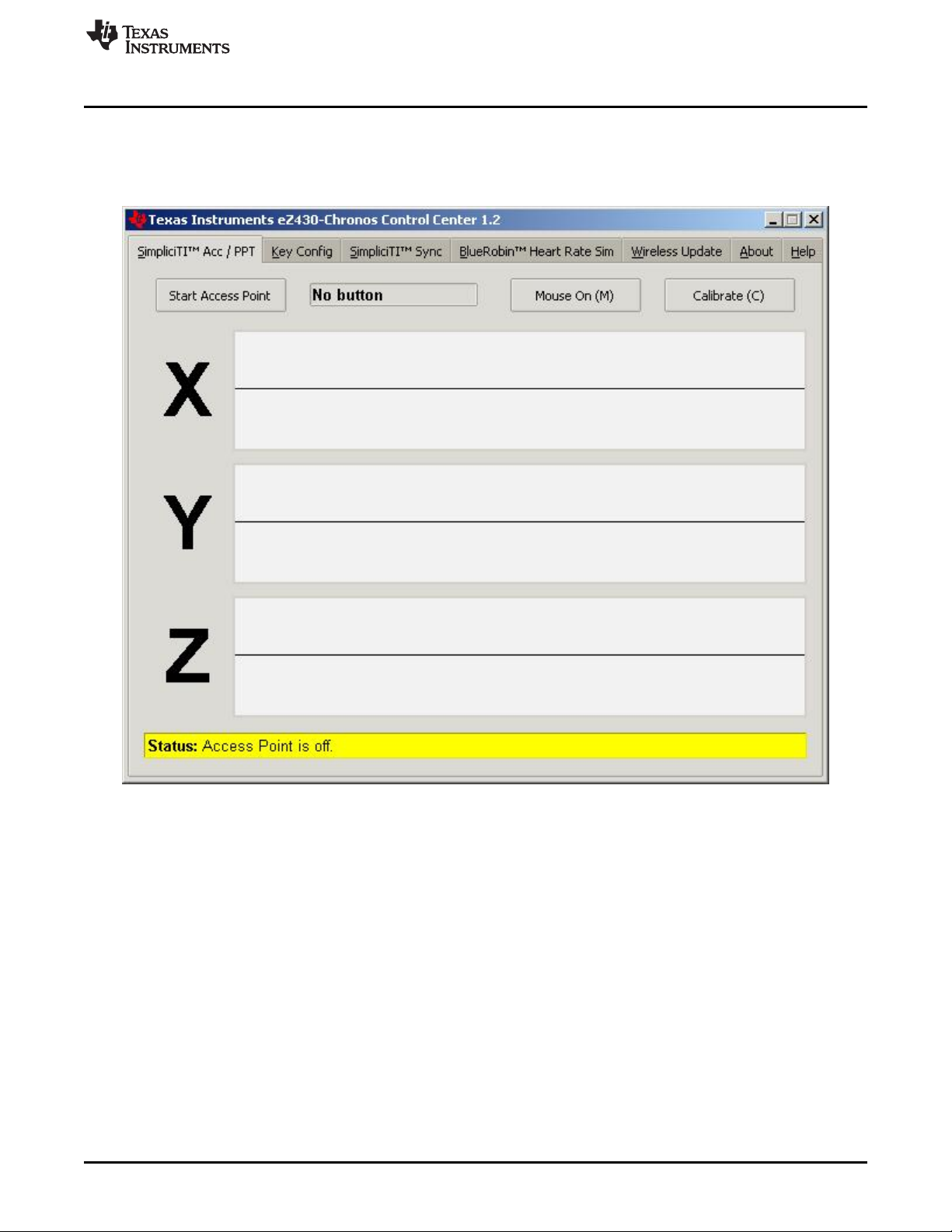
Figure 2-4. eZ430-Chronos Control Center
2.3.1 Transmission of Acceleration Data and Button Pushes
1. Select the SimpliciTI Acc/PPT tab.
2. Click Start Access Point to start PC. When the PC is ready, the control center status line displays
"Access point started. Now start watch in ACC, PPT or synch mode".
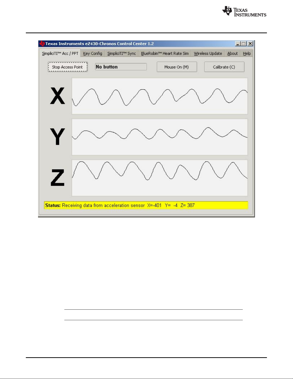
3. Select the ACC mode in the bottom LCD line of the eZ430-Chronos module and active the data
transmission by pressing the DOWN button. The Chronos module connects to the PC (this may take a
few seconds) and starts transmitting 3-Axis acceleration values
4. After connection, the Control Center status bar reports "Receiving data from acceleration sensor" and
the values according to the axis. The graphs display the acceleration data of the Chronos module for
each axis.
SLAU292F–November 2009–Revised October 2013 Getting Started
Submit Documentation Feedback
Copyright © 2009–2013, Texas Instruments Incorporated
15
Page 16
Using the eZ430-Chronos Wrist Module With a PC
www.ti.com
Figure 2-5. eZ430-Chronos Control Center With Acceleration Data
2.3.1.1 PC Mouse Control
1. Click Mouse On (M) to control the PC mouse pointer with the eZ430-Chronos module. Hold the
Chronos module with its display facing up. The mouse pointer moves vertically (x-axis in Control
Center) when tilting the Chronos module forward/backward and moves vertically (y-axis in Control
Center) when tilting the Chronos module left/right. Mouse clicks are possible as well:
• Left single click: * button
• Left double click: # button
• Right click: UP button
2. Mouse control can be calibrated to set a point of zero acceleration (that is, no pointer movement) by
selecting Calibration (C). It may be disabled by clicking Mouse Off (M) or by typing M on the PC
keyboard.
NOTE: Holding buttons (for example, for drag and drop) is not supported.
3. Turn the demo off by pushing the DOWN button on the eZ430-Chronos module and clicking Stop
Access Point in the PC application
16
Getting Started SLAU292F–November 2009–Revised October 2013
Copyright © 2009–2013, Texas Instruments Incorporated
Submit Documentation Feedback
Page 17

www.ti.com
2.3.1.2 PowerPoint Control
The Control Center allows the user to map button pushes on the wrist module into keystrokes on the PC.
The default setting is PowerPoint control, which allows switching slides forward/backward and to start the
slide show.
1. Select the SimpliciTI Acc/PPT tab.
2. Click Start Access Point to start linking. The control center status line displays "Access point started".
3. Select PPt mode in the bottom LCD line of the eZ430-Chronos module and activate the RF link by
pressing the DOWN button. The wrist module connects to the PC, this may take a moment.
4. Once connected, the Control Center status bar show when a button is pushed.
5. Open a PowerPoint presentation. Press # to go to presentation mode (slide show - F5), UP to switch to
next slide (right arrow key), and * (left arrow key) to switch to previous slide.
NOTE: To avoid bouncing of the Chronos buttons, a delay of 0.6 seconds between transmissions is
implemented; that is, if a button is pressed twice in less than 0.6 seconds, it is translated into
one keystroke only.
The eZ430-Chronos Control Center allows to the user to define other short cuts; for example,
to control a music or video player. See Section 3.3.2 for details.
For troubleshooting tips, see Appendix A, Frequently Asked Questions.
Using the eZ430-Chronos Wrist Module With a PC
SLAU292F–November 2009–Revised October 2013 Getting Started
Submit Documentation Feedback
Copyright © 2009–2013, Texas Instruments Incorporated
17
Page 18

Chapter 3
SLAU292F–November 2009–Revised October 2013
eZ430-Chronos Software
3.1 Overview
This chapter describes the software that is included in the eZ430-Chronos kit. Different projects and PC
user interfaces are available:
• eZ430-Chronos module demo software
• Control Center PC software for Windows and Linux
• eZ430-Chronos module data logger
• Data logger PC software for Windows and Linux
Many features of the eZ430-Chronos kit are based on TI's SimpliciTI protocol stack. However, the
Chronos module can also be used as a heart-rate monitor. For this purpose, the BlueRobin™ ultralowpower protocol stack can be used.
protocol stacks are selected automatically, depending on which feature is used.
3.2 eZ430-Chronos Demo Software
The sports firmware (default) of the Chronos module provides a broad set of features. In addition to basic
Chronos module functions such as time, date, alarm, and stopwatch, other advanced features such as an
altimeter, heart-rate monitor, calorie, vertical speed, and distance information
accelerometer provides acceleration data on the wrist module LCD and allows control of a PC by
transferring the sensor's measurements. The Chronos module can also be used to control PowerPoint or
other PC software with its buttons.
User concept:
The different features are either available in the top or bottom LCD line.
There are three user modes available: Modes such as Time or Date, Secondary Functions that allow
activation and deactivation of features (for example, to start or stop the stopwatch or to enable or disable
the alarm), and Set Functions that allow changing settings (for example, setting the time or date or
resetting the stopwatch) (see Figure 3-1).
• Modes: The different modes can be selected by using the button left of the corresponding LCD line.
Examples:
The * button allows selecting the top line mode
The # button allows changing the bottom line modes
• Secondary Functions: Secondary functions provide an extension to the selected mode and are
available through the button to the right of the corresponding LCD line.
Examples:
Toggling between time (HH:MM) and seconds (.SS) in time mode: push UP button to toggle between
modes.
Start or Stop in stopwatch mode: push DOWN to start or stop stopwatch
• Set Functions: Time, date, and other options can be set by holding the button to the left of the
corresponding LCD line.
Examples:
(1)
(2)
To set the time (shown in top LCD line): hold the * button to enter the time set menu.
BlueRobin is available from BM wireless at www.bmwireless.com.
For heart-rate monitor, calorie, vertical speed, and distance information, additional accessories or the eZ430-Chronos Control Center
heart rate simulation required.
(1)
is implemented on the wrist module and USB access point. The
(2)
are available. The internal
18
eZ430-Chronos Software SLAU292F–November 2009–Revised October 2013
Copyright © 2009–2013, Texas Instruments Incorporated
Submit Documentation Feedback
Page 19
Top Modes
Bottom Modes
* button for
mode selection
UP button for
alternate functions
# button for
mode selection
DOWN button for
alternate functions
Seconds
HR
On or Off
ACC
On or Off
Year
Start or
Stop
Hold * button for
set functions
Set
Time
Calibrate
Altitude
Tilt
Z-Axis
Tilt
X-Axis
Alarm
On or Off
Time
Alarm
Temp
Heart
Rate
Altitude
Speed
Tilt
Y-Axis
Date
Stop
watch
Battery
PPTACC SYNC Calories
Set
Alarm
Calibrate
Temp
To modify values in set functions, press UP or DOWN to select values, # for the next item, and * to save.
RFBSL
SYNC
On or Off
Distance
Start
Update
PPT
On or Off
Set
Date
To modify values in set functions, press UP or DOWN to select values, # for the next item, and * to save.
Reset
to Zero
Calorie
Settings
Hold # button for
set functions
www.ti.com
An exception to the above modes is the Keylock. It allows locking the buttons to avoid accidental change
or activation of modes (for example, when the Chronos module is carried in a suitcase or bag). The
keylock may be enabled or disabled by holding # and DOWN simultaneously for three seconds. The LCD
shows "Loct" when the keylock is active and "oPEn" when it is inactive.
eZ430-Chronos Demo Software
To reset the stopwatch (shown in bottom LCD line): hold the # button to reset.
Note: Heart rate can be generated by eZ430-Chronos Control Center. Optional heart-rate monitor is available
from BM innovations at www.bm-innovations.com/chronos.
Figure 3-1. eZ430-Chronos Feature Overview and Menu Structure
SLAU292F–November 2009–Revised October 2013 eZ430-Chronos Software
Submit Documentation Feedback
Copyright © 2009–2013, Texas Instruments Incorporated
19
Page 20

eZ430-Chronos Demo Software
3.2.1 Detailed Feature Overview - Modes Using the Top LCD Line
3.2.1.1 Time Mode
Press * until the time mode is active (see Figure 3-1 for details).
Secondary function: Seconds. Press UP to activate the alternative display. To return to the HH:MM
mode, push the UP button again.
Set function: Setting the time.
1. Hold * for three seconds until the time disappears and 12H or 24H is shown on the LCD.
2. Select 12H or 24H mode by pushing the UP or DOWN buttons.
3. Press # to continue with the time adjustment.
4. Set the hours by pushing the UP or DOWN button.
5. Press # to continue with the minutes adjustment.
6. Set the minutes by pushing the UP or DOWN button.
7. Press # to continue with the second adjustment.
8. Set the seconds by pushing the UP or DOWN button.
9. Press * to confirm the settings and go back to normal operation, or press # to start over with step 2.
NOTE: If no button is pressed for more than 30 seconds, the previous settings are restored.
www.ti.com
3.2.1.2 Alarm Mode
Press * until the alarm mode is active (see Figure 3-1 for details). The alarm mode can be distinguished
from time mode by an alarm symbol (bell) that flashes when the alarm time is displayed.
Secondary function: Alarm on or off. Press UP to enable or disable the alarm. The settings are
confirmed by "on" and "off" in the top LCD line. The bell icon stays on in all other modes when the alarm is
enabled and does not appear when the alarm is disabled.
Set function: Setting the alarm time.
1. Hold * for three seconds until the alarm time hour starts to flash.
2. Set the hours by pushing the UP or DOWN button.
3. Press # to continue with the minutes adjustment.
4. Set the minutes by pushing the UP or DOWN button.
5. Press * to confirm the settings and go back to normal operation, or press # to start over with step 2.
NOTE: If no button is pressed for more than 30 seconds, the previous settings are restored.
20
eZ430-Chronos Software SLAU292F–November 2009–Revised October 2013
Copyright © 2009–2013, Texas Instruments Incorporated
Submit Documentation Feedback
Page 21

www.ti.com
3.2.1.3 Temperature Mode
Press * until the temperature mode is active (see Figure 3-1 for details). The temperature can be shown in
degree Celsius or Fahrenheit. The selection depends on the time mode setting. In 12H mode, the
temperature is shown in degrees Fahrenheit, in 24H mode in degrees Celsius. The temperature is
measured in 1-second intervals. Positive temperatures are marked with a small arrow pointing up in the
upper LCD line, left of the temperature. An arrow pointing down indicated temperatures below zero.
Secondary function: None
Set function: Temperature calibration (can also calibrated from PC software in Sync mode, see
Section 3.3).
1. Hold * for three seconds until the temperature starts to flash.
2. Set the temperatures by pushing the UP or DOWN button.
3. Press * to confirm the settings.
NOTE: The temperature is measured inside the wrist module by the CC430 device. When the wrist
module is worn, its temperature may be different from the surrounding temperature due to
body heat. For accurate temperature measurements, do not wear the wrist module and allow
a sufficient amount of time for the wrist module to adapt to the surrounding temperature.
3.2.1.4 Altimeter Mode
Press * until the altimeter alarm mode is active (see Figure 3-1 for details). The altitude can be shown in
metric or imperial units. In 12H time mode, the altitude is shown in imperial units. In 24H time mode, the
altitude is shown in metric units. The altitude is measured only when the altimeter mode is active, and
measurement are made in intervals of 1 second.
The implementation of the altitude algorithm is done according to the VTI's application report AN33 without
any additional low-power optimizations. Therefore, the altimeter is active only in altimeter mode. In
addition, a timeout deactivates the measurements after 60 minutes. Altitudes above sea level are
indicated with a small arrow pointing up in the upper LCD line, left of the altitude. Altitudes below sea level
are indicated with a small arrow pointing down.
The altimeter algorithm is based on the air pressure and the ambient temperature. Therefore, changes in
air pressure affect the altitude accuracy. For precise measurements, the altimeter must be calibrated
manually for weather changes.
eZ430-Chronos Demo Software
NOTE: For most accurate altitude measurement, the wrist module must be fully exposed to the
ambient temperature (that is, the wrist module should not be worn directly on the arm),
because temperature is part of the altitude measurement (see Section 3.2.1.3).
Secondary function: Re-activate altimeter after timeout
Set function: Altitude calibration
1. Hold * for three seconds until the altitude starts to flash.
2. Set the altitude by pushing the UP or DOWN button.
3. Press * to confirm the settings.
SLAU292F–November 2009–Revised October 2013 eZ430-Chronos Software
Submit Documentation Feedback
Copyright © 2009–2013, Texas Instruments Incorporated
21
Page 22

eZ430-Chronos Demo Software
3.2.1.5 Heart Rate Mode - RF
Press * until the heart icon appears on the display that is heart rate mode is active (see Figure 3-1 for
details). When this mode is active, heart rate is shown and burned calories are determined (additional
settings must be made for first time use, see Section 3.2.2.7). For information on how to use the chest
belt, see to the documentation included with the heart-rate monitor device.
NOTE: This mode requires a heart-rate monitor (chest belt) that is not included in this kit, but
available from BM innovations, Germany (see www.bm-innovations.com/chronos). However,
a heart rate can be simulated without a chest belt by the eZ430-Chronos Control Center, see
Section 3.3 for details.
While almost all other eZ430-Chronos functions are based on TI's SimpliciTI protocol, the
heart-rate monitoring uses BlueRobin, an ultralow-power low-data-rate wireless
communication protocol from BM innovations.
Secondary function: Heart rate display on/off. Press UP to enable or disable the heart-rate monitoring.
Once a connection is established, the heart rate is shown on the top LCD line
Set function: None
www.ti.com
(3)
3.2.1.6 Speed Mode - RF
(4)
Press * until the "mi/h" or "km/h" icon is shown on the display; that is, the speed mode is active (see
Figure 3-1). Your running speed is shown on the LCD top line.
NOTE: This mode requires a heart-rate monitor (chest belt) which includes an accelerometer to
determine running speed. Visit BM innovations at www.bm-innovations.com/chronos for
available additions. However, speed can be simulated without a chest belt by the eZ430Chronos Control Center, see Section 3.3.4 for details.
While almost all other eZ430-Chronos functions are based on TI's SimpliciTI protocol, the
speed mode uses BlueRobin, an ultralow-power low-data-rate wireless communication
protocol from BM innovations.
Secondary function: None
Set function: None
3.2.1.7 Tilt Mode
Press * until the tilt mode is active (see Figure 3-1). The acceleration is shown in G (9.81 m/s2) for all
three axes. After entering the tilt mode, the y-axis acceleration is shown by default, and the z-axis or xaxis can be selected. Positive acceleration values are marked with a small arrow pointing up in the top
LCD line, left of the acceleration. Negative acceleration values are marked with a small arrow pointing
down. After 60 minutes, a timeout deactivates the measurements.
Secondary function: Select axis. The default is y-axis, followed by z-axis and x-axis.
Set function: None
(3)
Additional accessory or eZ430-Chronos Control Center heart rate simulation required.
(4)
Additional accessory or eZ430-Chronos Control Center heart rate simulation required.
22
eZ430-Chronos Software SLAU292F–November 2009–Revised October 2013
Copyright © 2009–2013, Texas Instruments Incorporated
Submit Documentation Feedback
Page 23

www.ti.com
3.2.2 Detailed Feature Overview - Modes Using the Bottom LCD Line
3.2.2.1 Date Mode
Press # until the date mode is active (see Figure 3-1).
Secondary function: Year. Press DOWN to activate the alternative display. To return to day and month,
push the DOWN button again.
Set function: Setting the date
1. Push the # button until the date is displayed in the bottom LCD line.
2. Hold # for three seconds until the year flashes on the bottom LCD line.
3. Set the year by pushing the UP or DOWN button.
4. Press # to continue with the month adjustment.
5. Set the month by pushing the UP or DOWN button.
6. Press # to continue with the day adjustment.
7. Set the day by pushing the UP or DOWN button. Press * to confirm the settings and go back to normal
operation, or press # to start over with step 3.
NOTE: If no key is pressed for more than 30 seconds, the previous settings are restored.
eZ430-Chronos Demo Software
3.2.2.2 Stopwatch Mode
Press # until the stopwatch mode is active (see Figure 3-1). It supports up time intervals up to 19 hours,
59 minutes and 59 seconds. For the first 20 minutes, the resolution is 1/100 second, after 20 minutes the
resolution changes to 1 second.
Secondary function: Start and stop. Press DOWN to start or stop the stopwatch
Set function: Reset stopwatch.
Hold the # button until the stopwatch is set to zero.
3.2.2.3 Battery Voltage Mode
Press # until the battery voltage is shown (see Figure 3-1). It is updated once per minute.
Secondary function: None
Set function: None
3.2.2.4 Acceleration Mode - RF
This mode requires the eZ430-Chronos Control Center PC software.
Press # until "ACC" is shown on the LCD (see Figure 3-1). This mode provide a continuous transmission
of 3D acceleration from the Chronos module using TI's SimpliciTI protocol stack. In addition, the Chronos
module transmits a signal when the #, *, or UP buttons are pushed.
Secondary function: Start or stop transmission of acceleration data. Pushing DOWN starts/stops the
pairing process or stop the transmission (the access point on the PC must be started first from the eZ430Chronos Control Center (see Section 3.3.1). The RF icon on the LCD flashes when the radio is active. If
the pairing fails, it disappears. The top LCD line shows the time during the pairing and until the data
transmission is disabled.
Set function: None
SLAU292F–November 2009–Revised October 2013 eZ430-Chronos Software
Submit Documentation Feedback
Copyright © 2009–2013, Texas Instruments Incorporated
23
Page 24

eZ430-Chronos Demo Software
3.2.2.5 PowerPoint Mode - RF
This mode requires the eZ430-Chronos Control Center PC software.
Press # until PPt is shown (see Figure 3-1). This mode allows control of a PowerPoint presentation by
translating button pushes on the Chronos module into keystrokes of the PC keyboard. No acceleration or
other data is transmitted. The default settings are:
• # : Go to presentation mode (F5)
• * : Previous slide (Left)
• UP : Next slide (Right)
The Control Center allows user defined key settings (including combinations) (see Section 3.3.2).
Secondary function: Start or stop transmission of button pushes. Pushing DOWN starts/stops the pairing
process or stops the transmission (the access point on the PC must be started from the eZ430-Chronos
Control Center (see Section 3.3.1). The RF icon on the LCD flashes when the radio is active; if pairing
fails, the icon disappears. The top LCD line shows the time during the pairing until the data transmission is
disabled.
Set function: None
3.2.2.6 Sync Mode - RF
This mode requires the eZ430-Chronos Control Center PC software.
Press # until "SYnC" is shown (see Figure 3-1). This mode allows doing a variety of settings for the wrist
module conveniently from the eZ430-Chronos Control Center PC software over the air (see Section 3.3.3).
• Time settings
• Date settings
• Altitude calibration
• Temperature calibration
Secondary function: Start or stop link for Sync Mode. Pushing DOWN starts/stops the pairing process or
stop the link (the access point on the PC must be started first from the eZ430-Chronos Control Center
(see Section 3.3.3). The RF icon on the LCD flashes when the radio is active. If the pairing fails, it
disappears. After a successfully received message, the LCD shows "DONE". The top LCD line is off
during the pairing and until the Sync Mode is disabled.
Set function: None
www.ti.com
24
eZ430-Chronos Software SLAU292F–November 2009–Revised October 2013
Copyright © 2009–2013, Texas Instruments Incorporated
Submit Documentation Feedback
Page 25

www.ti.com
3.2.2.7 Calorie/Distance Mode - RF
Press # until the "kcal" icon appears (see Figure 3-1). This mode shows the amount of calories that were
burned while exercising, if the optional chest belt is used and heart rate mode is active. This mode also
provides the distance (for example, when running) if a chest belt with build-in accelerometer is used. For
accurate calorie determination, users need to set their sex and weight.
Secondary function: Distance. Press DOWN to activate the alternative display. To return to Calorie
Mode, push the DOWN button again.
Set function: (Re-)setting calories and setting user weight and sex.
1. Push the # button until the calories is displayed in the bottom LCD line
2. Hold # for three seconds until the calorie value flashes on the bottom LCD line
3. (Re-)set the calories by pushing UP or DOWN
4. Press # to continue with the user sex adjustment
5. Set the user sex by pushing UP or DOWN
6. Press # to continue with user weight adjustment
7. Set the user weight (lb in 12H time mode, kg in 24H time mode) by pushing UP or DOWN
8. Press * to confirm the settings and go back to normal operation, or press # to start over with step 3
NOTE: If no key is pressed for more than 30 seconds, the previous settings are restored.
eZ430-Chronos Demo Software
(5)
3.2.2.8 Wireless Update - RF
This mode requires the eZ430-Chronos Control Center PC software.
Press # until the "rFbSL" is shown (see Figure 3-1). This mode allows updating the firmware of the eZ430-
Chronos module wirelessly.
Secondary function: Start or restart the update process. Push DOWN once to switch to the confirmation
menu "CONF". Pushing DOWN again starts or restarts the update process (the wireless update on the PC
must be started from the eZ430-Chronos Control Center first (see Section 3.3.1)). At the beginning of the
update the LCD shows "rAM" for a few seconds. During this time, the update software is downloaded from
the PC to the RAM of the CC430 on the Chronos module. This program contains all memory write and
LCD routines. After this transfer is finished, the code is executed from RAM, and the download of the
actual firmware file is started. The LCD shows the progress in percent on the upper LCD line. After the
transfer is complete, a reset starts the software on the Chronos module. See Section 3.6.3 for details.
NOTE: When the wireless update is activated on the Chronos module, it returns to the main
application only with a reset, whether or not an update was performed. Time, data, alarm,
and other RAM-based data are lost.
(5)
Additional accessory or eZ430-Chronos Control Center heart rate simulation required.
SLAU292F–November 2009–Revised October 2013 eZ430-Chronos Software
Submit Documentation Feedback
Copyright © 2009–2013, Texas Instruments Incorporated
25
Page 26

eZ430-Chronos Control Center PC Software
3.3 eZ430-Chronos Control Center PC Software
The eZ430-Chronos Control Center software provides several features demonstrating the wireless
capabilities of the kit on Windows and Linux operating systems. Different RF protocol stacks are
automatically selected for use, depending on the function. Available features:
• 3D acceleration graph with PC mouse control
• Wireless remote control / PowerPoint control
• Time, date, and calibration data synchronization tool
• Heart rate and speed simulator
• Wireless firmware update
NOTE: Connect the USB RF access point to the PC before launching the Control Center software.
For first time use, wait until Windows has finished the access point driver installation.
In case of problems on Windows PCs, check if the settings for the RF access point are
correct in the Windows Device Manager Start > Control Panel > System > Hardware >
Device Manager. The RF access point is listed under Ports (COM & LPT) as TI CC1111
Low-Power RF to USB CDC Serial Port (Chronos BLACK) or eZ430-ChronosAP (Chronos
WHITE). The port settings should be:
• Baud Rate: 115200
• Data bits: 8
• Parity: None
• Stop bits: 1
• Flow control: None
www.ti.com
In case of problems on Linux PCs, ensure that the correct tty setting is specified. Check /dev
for the new tty device after plugging in the RF access point. If the RF access point is
assigned to a device other than ttyACM0, either remove the serial device that occupies this
slot (for example, a modem), or change the script file variable "com" in eZ430Chronos_CC_1_2.tcl located in /home/<user name>/Texas Instruments/eZ430Chronos/Control Center/eZ430-Chronos Control Center.
To launch the Control Center software on a Windows PC, shortcuts are available on the Desktop and in
the Start Menu under Programs > Texas Instruments > eZ430-Chronos > eZ430-Chronos Control Center.
To launch the Control Center software on a Linux PC, browse to /home/<user name>/Texas
Instruments/eZ430-Chronos/Control Center/eZ430-Chronos Control Center and run eZ430Chronos_CC_1_2.tcl as root user.
The different features are grouped onto tabs of the Control Center window. The tabs also indicate which
radio protocol is used.
26
eZ430-Chronos Software SLAU292F–November 2009–Revised October 2013
Copyright © 2009–2013, Texas Instruments Incorporated
Submit Documentation Feedback
Page 27
www.ti.com
eZ430-Chronos Control Center PC Software
Figure 3-2. eZ430-Chronos Control Center
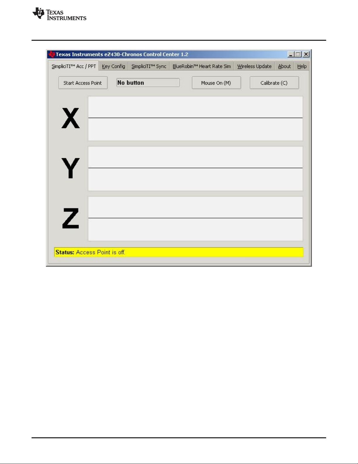
3.3.1 SimpliciTI™ Acc/PPT Tab (Mouse and PowerPoint Control)
The SimpliciTI Acc / PPT tab support two different features. It may be used to display the acceleration
data transmitted by the Chronos module, which can also be used to control the mouse pointer. It may also
be used to remotely control the PC with user-definable shortcuts such as PowerPoint control.
Pairing Chronos module and PC:
1. Activate the pairing on the PC by clicking Start Access Point. The control center status line displays
"Access point started. Now start watch in acc, ppt or sync mode" when the PC is ready
2. Select "ACC" or "PPt" on the eZ430-Chronos module by pushing the # button, depending on the
desired function - see detailed description in Section 3.3.1.1 or in Section 3.2.2.4.
3. Initiate pairing on the Chronos module by pushing the DOWN button to activate the selected mode
After a short time, the link is established.
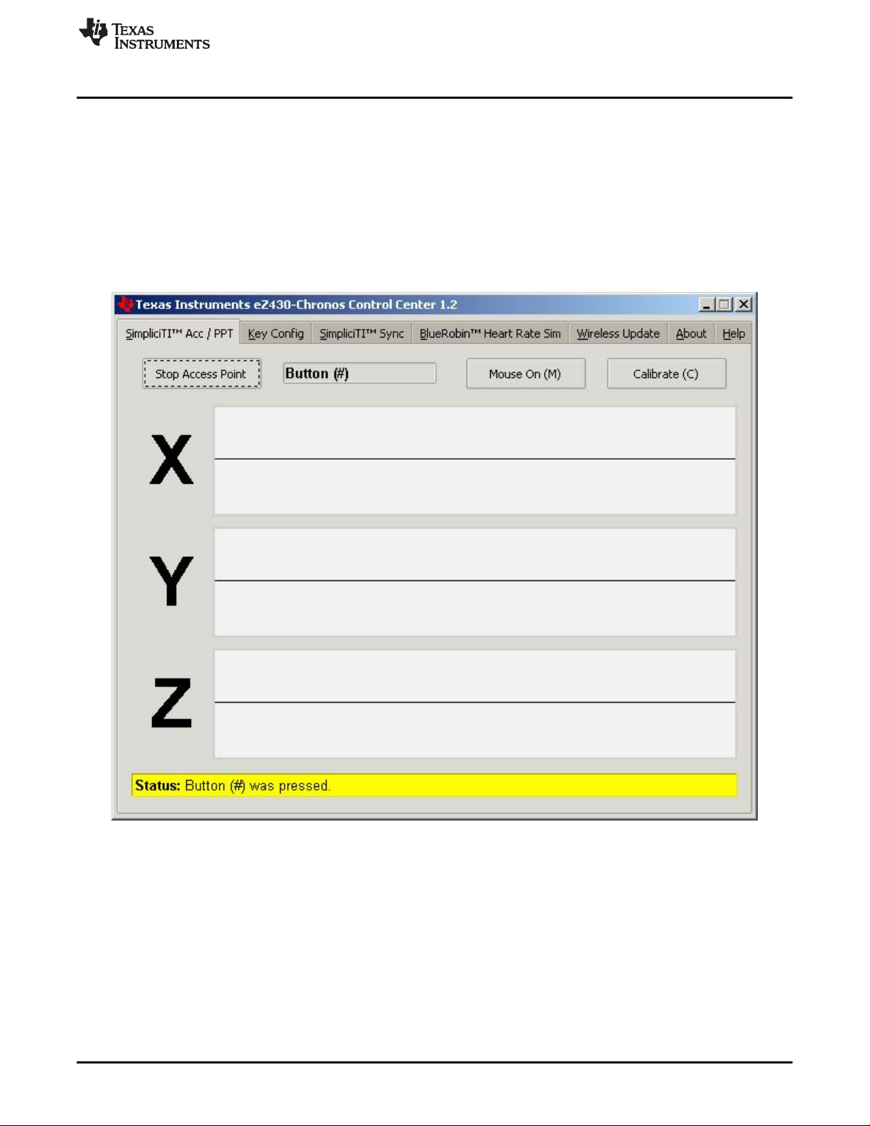
In "ACC" mode, the Control Center status bar shows:
"Receiving data from acceleration sensor X=... Y=... Z=...".
In PPt mode, the Control Center status bar reports which button is pushed (#, *, or UP).
SLAU292F–November 2009–Revised October 2013 eZ430-Chronos Software
Submit Documentation Feedback
Copyright © 2009–2013, Texas Instruments Incorporated
27
Page 28

eZ430-Chronos Control Center PC Software
3.3.1.1 Acc Mode
In this mode, the Chronos module constantly transmits acceleration data to the PC. In addition, #, *, and
UP button pushes are transferred. The Control Center software shows the 3D acceleration in graphs.
Optionally, mouse control can be activated by clicking on Mouse On (M) or by typing M on the keyboard.
Once active, the PC mouse pointer can be controlled by tilting the Chronos module. Hold the Chronos
module with its display facing up. The mouse pointer moves vertically (X-axis in Control Center) when
tilting the wrist module forward or backward and move vertically (Y-axis in Control Center) when tilting it
left or right. Mouse clicks are also possible–see the following description. Mouse control can be calibrated
(to set a point of zero acceleration or no pointer movement) by selecting Calibration (C). It may be
disabled by clicking Mouse Off (M) or by typing M on the PC keyboard.
• Left single click: * button
• Left double click: # button
• Right click: UP button
NOTE: Holding buttons (for example, to drag and drop) is not supported.
Turn the demo off by pushing the DOWN button on the eZ430-Chronos module and clicking "Stop Access
Point" in the PC application.
www.ti.com
28
Figure 3-3. eZ430-Chronos Control Center With Acceleration Data
eZ430-Chronos Software SLAU292F–November 2009–Revised October 2013
Copyright © 2009–2013, Texas Instruments Incorporated
Submit Documentation Feedback
Page 29
www.ti.com
3.3.1.2 PPT Mode
This mode allows using the eZ430-Chronos module as a simple PC remote control. Data is transmitted
only when either the #, *, or UP button is pushed. This information is mapped into keystrokes on the PC.
The default setting is PowerPoint control, and the buttons are mapped to:
• # to go to presentation mode (slide show - F5)
• UP to switch to next slide (right arrow key)
• * (left arrow key) to switch to previous slide
These settings can be changed to many other combinations; for example, such as controlling music
players or standard Windows functions (see Section 3.3.2 for details).
eZ430-Chronos Control Center PC Software
Figure 3-4. eZ430-Chronos Control Center With PPT Control
SLAU292F–November 2009–Revised October 2013 eZ430-Chronos Software
Submit Documentation Feedback
Copyright © 2009–2013, Texas Instruments Incorporated
29
Page 30

eZ430-Chronos Control Center PC Software
3.3.2 Key Configuration Tab
This tab contains the key mapping for the eZ430-Chronos module buttons #, * and UP. Besides a single
key selection (pulldown menu for each button), also full combinations including the Shift, Ctrl, Alt, and
Windows keys can be user defined by selecting the corresponding option. Changes can be made while
the PPT mode is active. Configurations can be saved by clicking the Save button.
Predefined configurations are available in a pull down menu on top of the menu. Select configuration from
menu and click Load to activate them.
Predefined key configurations:
• PowerPoint Control (eZ430-Chronos-CC.ini)
* = previous slide
UP = next slide
# = start presentation (F5)
• Windows Media Player (Media Player Control.ini)
* = previous song
UP = next song
# = start/pause
• iTunes (iTunes Control.ini)
* = previous song
UP = next song
# = start/pause
The key mapping may be changes while PPT mode is active.
www.ti.com
30
Figure 3-5. eZ430-Chronos Control Center Key Configuration
eZ430-Chronos Software SLAU292F–November 2009–Revised October 2013
Copyright © 2009–2013, Texas Instruments Incorporated
Submit Documentation Feedback
Page 31
www.ti.com
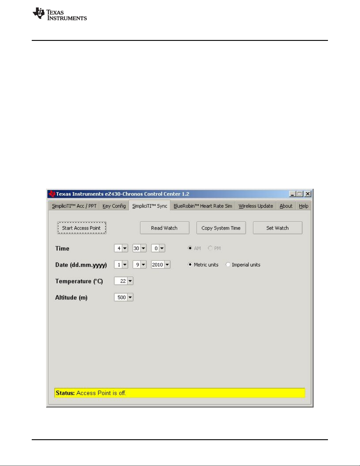
3.3.3 SimpliciTI™ Sync
The SimpliciTI Sync tab offers the possibility setting time/date of the Chronos module including calibration
data conveniently.
Pairing Chronos module and PC:
1. Activate the pairing on the PC by clicking Start Access Point. The Control Center status line displays
"Access point started. Now start watch in ACC, PPT or synch mode" when the PC is ready
2. Select "SYnC" on the eZ430-Chronos module by pushing the # button.
3. Initiate pairing on the Chronos module by pushing the DOWN button to activate the selected mode.
After a short time, the link is established.
Setting the Chronos module:
1. Select metric or imperial units
2. Enter calibration data for the temperature and altitude OR read back the data from the Chronos
module by clicking Read Watch.
3. Click Copy System Time to set the Chronos module according to read the PC system time.
4. Click Set Watch to transfer data to the Chronos module.
5. The Chronos module shows DONE.
6. Push the DOWN button on the Chronos module to end connection.
eZ430-Chronos Control Center PC Software
Figure 3-6. eZ430-Chronos Control Center Sync
SLAU292F–November 2009–Revised October 2013 eZ430-Chronos Software
Submit Documentation Feedback
Copyright © 2009–2013, Texas Instruments Incorporated
31
Page 32
eZ430-Chronos Control Center PC Software
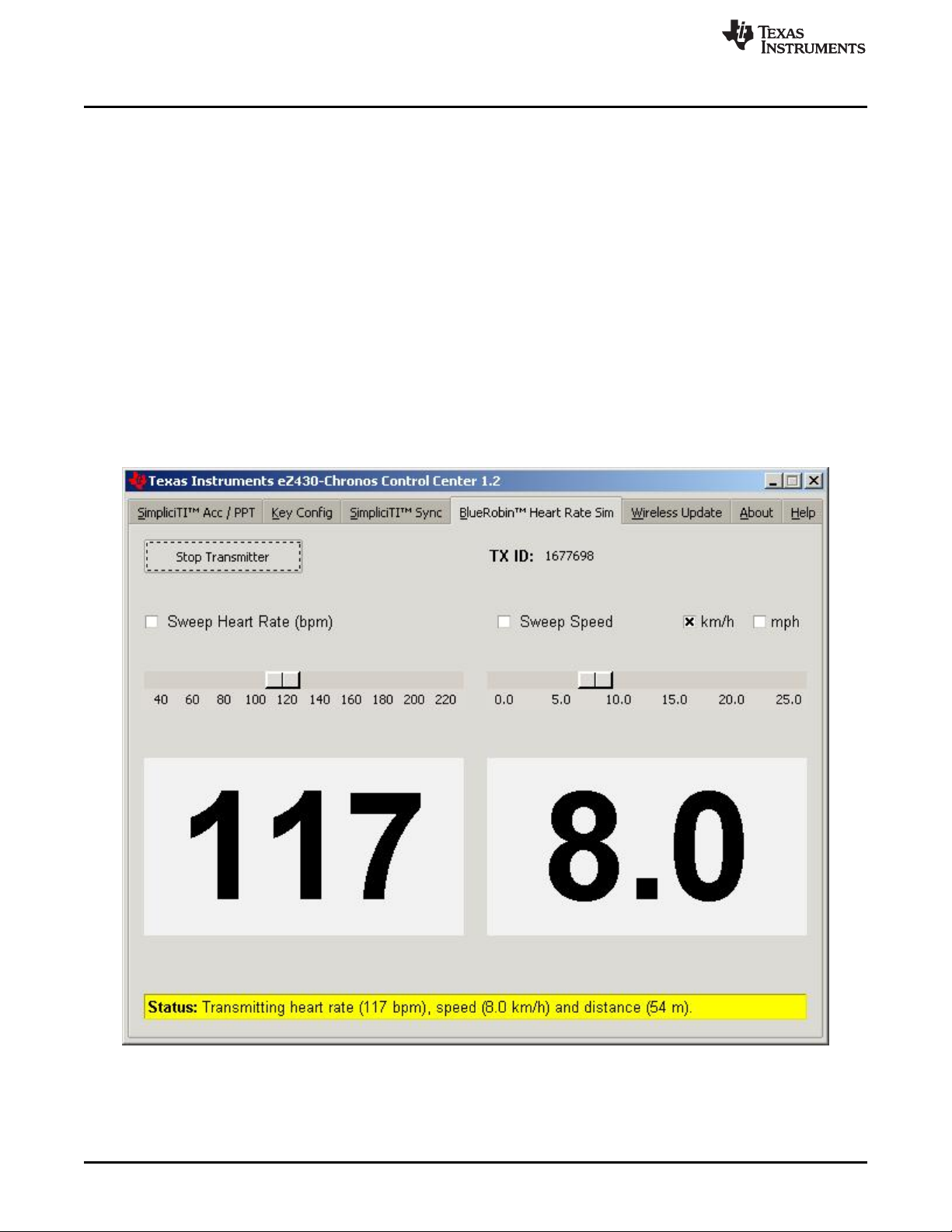
3.3.4 BlueRobin™ Heart Rate Simulator
This mode simulates an active heart rate chest belt. Besides the heart rate it may also be used to transfer
speed and distance data from the PC to the eZ430-Chronos wrist module.
Pairing Chronos module and PC:
1. Activate link on the PC by clicking Start Transmitter. The Control Center status line displays
"Transmitting heart rate (...bpm), speed (...km/h) and distance (...m)" when the PC is transmitting data.
The heart rate may be changed by the heart rate and speed sliders or by selecting "sweep" for
automatic heart rate and speed sweeping
2. Select heart rate mode (heart symbol is shown) by pushing the * button (see detailed description in
Section 3.2.1.5).
3. Start receiver on wrist module by pushing the UP button
4. After a short moment, the current heart rate is displayed
Speed can be selected by pushing the * button
Calories can be selected by pushing the # button
Distance can be selected by pushing the DOWN button in Calorie Mode (see Section 3.2.2.7).
5. The reception may be stopped by pushing UP while the heart rate is shown
www.ti.com
32
Figure 3-7. eZ430-Chronos Control Center Heart Rate Simulator
eZ430-Chronos Software SLAU292F–November 2009–Revised October 2013
Copyright © 2009–2013, Texas Instruments Incorporated
Submit Documentation Feedback
Page 33

www.ti.com
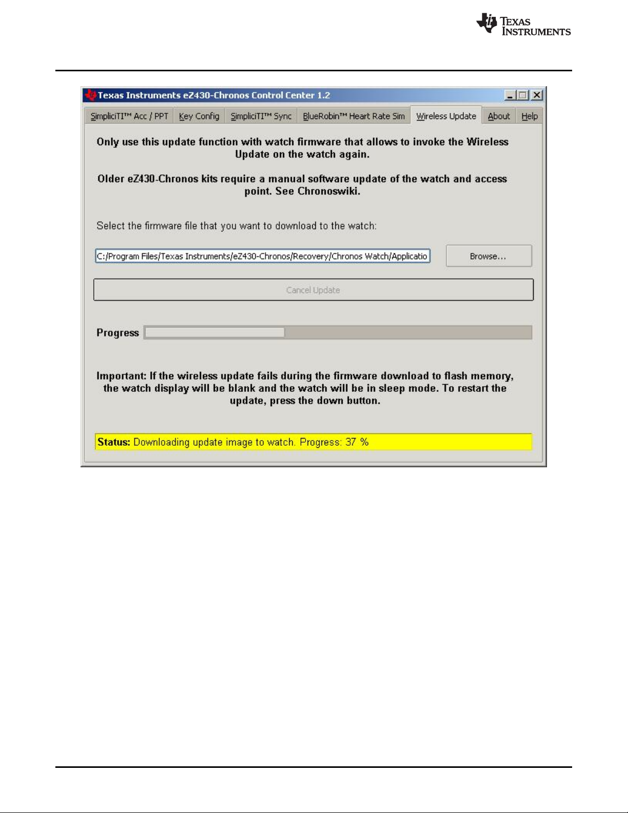
3.3.5 Wireless Update
This mode allows updating the firmware of the eZ430-Chronos wrist module wirelessly, without
disassembling it.
Update procedure:
1. Select CC430 flash image (.txt file) by clicking Browse.... Example images for the demo software and
the data logger application are located for Windows in C:\Program Files\Texas Instruments\eZ430Chronos\Recovery\Chronos Watch\Applications and for Linux in /home/<user name>/Texas
Instruments/eZ430-Chronos/Recovery/Chronos Watch/Applications.
NOTE: Ensure selecting the correct version of the flash images. If the wrong frequency is selected,
no wireless communication is possible anymore. In that case, the Chronos module must be
updated using the eZ430 debug interface.
Only transfer flash images to the Chronos module, which allow invoking the update software
on the Chronos module.
The file to be downloaded to the Chronos module must be in TI-TXT format to work with this
update procedure. This new firmware must reside within the main memory flash (0x8000 to
0xFFFF), otherwise the update procedure fails due to boundary checks on the Chronos
module side.
2. Activate the update mechanism on the PC by clicking Update eZ430-Chronos Watch. The Control
Center status line displays "Access point started. Now start watch in rFbSL mode" when the PC is
ready.
3. Select "rFbSL" on the eZ430-Chronos module by pushing the # button
4. Initiate update by pushing the DOWN button
5. After a short moment, the update is started
At the beginning of the update the LCD shows "rAM" for a few seconds. During this time, the actual
update software is downloaded from the PC to the RAM of the CC430 on the Chronos module. This
program contains all memory write and LCD routines. After this transfer is finished, the code is
executed from RAM, and the download of the firmware file is started. The LCD shows the progress in
percent on the upper LCD line. After the transfer is complete, a reset starts the software on the
Chronos module (see Section 3.6.3).
eZ430-Chronos Control Center PC Software
NOTE: If the update fails, it can be activated again by pushing the DOWN button again on the
eZ430-Chronos wrist module, given that the wireless update is active in the eZ430-Chronos
Control Center.
SLAU292F–November 2009–Revised October 2013 eZ430-Chronos Software
Submit Documentation Feedback
Copyright © 2009–2013, Texas Instruments Incorporated
33
Page 34
eZ430-Chronos Control Center PC Software
www.ti.com
34
Figure 3-8. eZ430-Chronos Control Center Wireless Update
eZ430-Chronos Software SLAU292F–November 2009–Revised October 2013
Copyright © 2009–2013, Texas Instruments Incorporated
Submit Documentation Feedback
Page 35

Top Modes
Bottom Modes
* button for
mode selection
UP button for
alternate functions
# button for
mode selection
DOWN button for
alternate functions
Seconds
HR
On or Off
SYNC
On or Off
Year
Logger
On or Off
Start
Update
Time
Temp
Altitude
Heart
Rate
Date
Data
Logger
RFBSLSYNC
www.ti.com
3.4 eZ430-Chronos Data Logger
Besides the demo software, the eZ430-Chronos kit comes with an additional software project that turns
the Chronos module into a data logger. Heart rate
definable intervals of 1 to 255 seconds. 8KB of flash memory is reserved for logging several hours up to
days, depending on the settings. The stored data can be transferred to a PC (in CSV format) and used for
further analysis. The data logger provides fewer features compared to the demo software as memory is
freed for data storage. Most importantly, no Set Functions are available (that is, the Chronos module
cannot be set or calibrated standalone); however, calibration can be done conveniently by using the
eZ430-Chronos Data Logger PC software. The software project for CCS can be found in C:\Program
Files\Texas Instruments\eZ430-Chronos\Software Projects\Chronos Watch\CCS\Data Logger and for IAR
in C:\Program Files\Texas Instruments\eZ430-Chronos\Software Projects\Chronos Watch\IAR\Data
Logger.
Available features:
• Time and Date
• Temperature
• Altitude
• Heart rate
• Sync
• Wireless firmware update
• Data logger
• Battery monitoring
eZ430-Chronos Data Logger
(6)
, temperature, and altitude can be logged in user
NOTE: No Set Functions are available in this software. All settings can be done using the eZ430-
Chronos Data Logger PC software.
User concept:
The user concept and the modes remain the same as in the demo software except for the Set Functions
(see Section 2.1).
(6)
Heart rate can be generated by eZ430-Chronos Control Center. Optional heart-rate monitor is available from BM innovations at www.bm-
innovations.com/chronos.
SLAU292F–November 2009–Revised October 2013 eZ430-Chronos Software
Submit Documentation Feedback
Figure 3-9. eZ430-Chronos Data Logger Feature Overview and Menu Structure
Copyright © 2009–2013, Texas Instruments Incorporated
35
Page 36

Data Logger PC Software
3.4.1 Detailed Feature Overview
As all available modes remain the same in the Data Logger software, only the additions are described in
this section.
3.4.1.1 Data Logger Mode
The data logger mode can be selected by pushing the # button until the bottom LCD line shows "dLog". It
may be enabled or disabled by pushing the DOWN button. If the heart rate data logging is selected (see
Section 3.5 ) in data logger PC software, the heart-rate monitor is automatically enabled (the RF icon
flashes until linked to a heart-rate monitor). When active, the record icon on the LCD is on (see Figure 1-
1).
NOTE: Connect the USB RF access point to the PC before launching the Control Center software.
For first time use, wait until Windows has finished the access point driver installation.
In case of problems on Windows PCs, check if the settings for the RF access point are
correct in the Windows Device Manager Start > Control Panel > System > Hardware >
Device Manager. The RF access point is listed under Ports (COM & LPT) as TI CC1111
Low-Power RF to USB CDC Serial Port (Chronos BLACK) or eZ430-ChronosAP (Chronos
WHITE). The port settings should be:
• Baud Rate: 115200
• Data bits: 8
• Parity: None
• Stop bits: 1
• Flow control: None
www.ti.com
In case of problems on Linux PCs, ensure that the correct tty setting is specified. Check /dev
for the new tty device after plugging in the RF access point. If the RF access point is
assigned to a device other than ttyACM0, either remove the serial device that occupies this
slot (for example, a modem), or change the script file variable "com" in eZ430-
Chronos_Datalogger_1_2.tcl located in /home/<user name>/Texas Instruments/eZ430Chronos/Control Center/eZ430-Chronos Data Logger.
To launch the Control Center software, shortcuts are available in the Start Menu under Programs >
Texas Instruments > eZ430-Chronos > eZ430-Chronos Data Logger.
3.5 Data Logger PC Software
The eZ430-Chronos data logger PC software allows reading out logged data from the Chronos module. It
can also be used to set and calibrate the Chronos module, as its set modes were removed to free up as
much memory as possible for data logging. Available features:
• Time, date, and calibration data synchronization tool
• Read out of logged data
• Wireless firmware update
To launch the eZ430-Chronos Data Logger software on a Windows PC, shortcuts are available on the
Desktop and in the Start Menu under Programs > Texas Instruments > eZ430-Chronos > eZ430-Chronos
Data Logger.
To launch the eZ430-Chronos Data Logger software on a Linux PC, browse to /home/<user name>/Texas
Instruments/eZ430-Chronos/Control Center/eZ430-Chronos Data Logger and run eZ430Chronos_Datalogger_1_2.tcl as root user.
36
eZ430-Chronos Software SLAU292F–November 2009–Revised October 2013
Copyright © 2009–2013, Texas Instruments Incorporated
Submit Documentation Feedback
Page 37

www.ti.com
3.5.1 SimpliciTI Data Logger
The SimpliciTI Sync tab offers the possibility setting time/date of the wrist module including calibration
data besides reading out logged data.
Pairing Chronos module and PC:
1. Activate the pairing on the PC by clicking Start Access Point. When the PC is ready, the eZ430Chronos Data Logger status line displays Access point started. Now start watch in acc, ppt or sync
mode.
2. Select SYnC on the eZ430-Chronos module by pushing the # button (see detailed description in
Section 3.3.3).
3. Initiate pairing on the wrist module by pushing the DOWN button to activate the selected mode. After a
short time, the link is established
Setting the Chronos module:
1. Select metric or imperial units.
2. Enter calibration data for the temperature and altitude or read back the data from the Chronos module
by clicking Read Watch.
3. Specify the data that should be logged.
4. Define logging time interval (1 to 255 seconds) in which data is stored.
5. Click Copy System Time to set the Chronos module according to read the PC's system time.
6. Click Set Watch to transfer data to the Chronos module.
7. The Chronos module shows DONE.
8. Push the DOWN button on the Chronos module to end connection
Reading out logged data:
1. Pair the wrist module with PC in case not linked yet (see the previous section, Pairing Chronos module
and PC)
2. Specify file name and location of log file
3. Click Download to start data transfer
4. Push the DOWN button to stop connection when the transfer has finished.
The log file is stored in CSV format. Its content appears as one line per log. Each line starts with date,
time, heart rate, temperature, and altitude. Parameters which were not logged are set to zero (according
to settings in eZ430-Chronos Data Logger PC software).
Data Logger PC Software
SLAU292F–November 2009–Revised October 2013 eZ430-Chronos Software
Submit Documentation Feedback
Copyright © 2009–2013, Texas Instruments Incorporated
37
Page 38
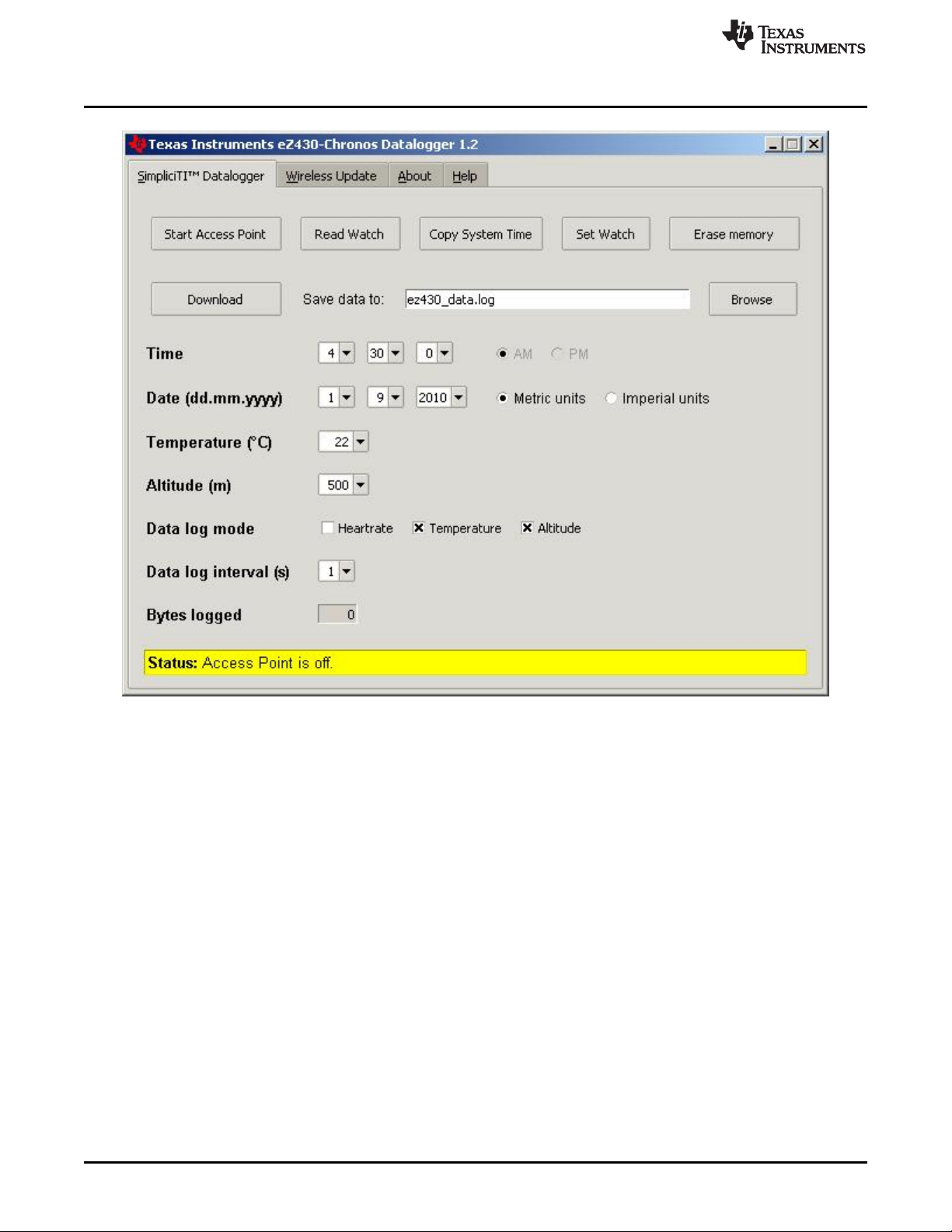
Data Logger PC Software
www.ti.com
Figure 3-10. eZ430-Chronos Data Logger
38
eZ430-Chronos Software SLAU292F–November 2009–Revised October 2013
Copyright © 2009–2013, Texas Instruments Incorporated
Submit Documentation Feedback
Page 39

www.ti.com
3.5.2 Wireless Update
This mode allows updating the firmware of the eZ430-Chronos wrist module wirelessly, without
disassembling it.
Update procedure:
1. Select CC430 flash image (.txt file) by clicking Browse.... Example images for the demo software and
the data logger application are located for Windows in C:\Program Files\Texas Instruments\eZ430-
Chronos\Recovery\Chronos Watch\Applications and for Linux in /home/<user name>/Texas
Instruments/eZ430-Chronos/Recovery/Chronos Watch/Applications.
NOTE: Ensure selecting the correct version of the flash images. If the wrong frequency is selected,
no wireless communication is possible anymore. In that case, the wrist module must be
updated using the eZ430 debug interface.
Only transfer flash images to the Chronos module, which allow invoking the update software
on the Chronos module.
The file to be downloaded to the Chronos module must be in TI-TXT format to work with this
update procedure. This new firmware must reside within the main memory flash (0x8000 to
0xFFFF), otherwise the update procedure fails due to boundary checks on the Chronos
module side.
2. Activate the update mechanism on the PC by clicking Update eZ430-Chronos Watch. The Control
Center status line displays "Access point started. Now start watch in rFbSL mode" when the PC is
ready.
3. Select "rFbSL" on the eZ430-Chronos wrist module by pushing the # button
4. Push once DOWN button to switch to confirmation menu
5. Push DOWN again to initiate update
6. After a short moment, the update is started
At the beginning of the update the LCD shows "rAM" for a few seconds. During this time, the actual
update software is downloaded from the PC to the RAM of the CC430 on the Chronos module. This
program contains all memory write and LCD routines. After this transfer is finished, the code is
executed from RAM, and the download of the firmware file is started. The LCD shows the progress in
percent on the upper LCD line. After the transfer is complete, a reset starts the software on the
Chronos module. See Section 3.6.3 for details.
Data Logger PC Software
NOTE: If the update fails, it can be activated again by pushing the DOWN button again on the
eZ430-Chronos wrist module, given that the wireless update is active in the eZ430-Chronos
Control Center.
SLAU292F–November 2009–Revised October 2013 eZ430-Chronos Software
Submit Documentation Feedback
Copyright © 2009–2013, Texas Instruments Incorporated
39
Page 40
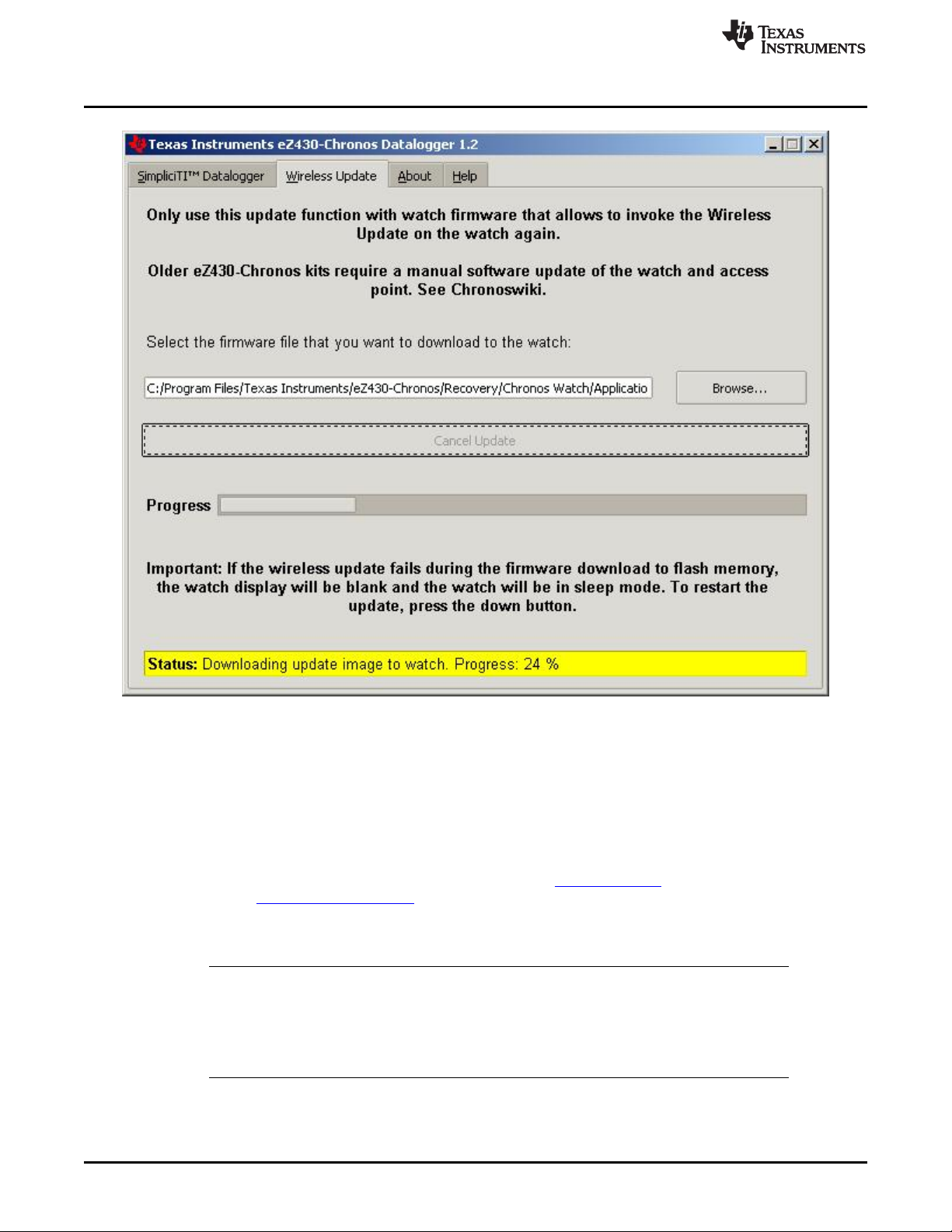
eZ430-Chronos Software Projects
www.ti.com
Figure 3-11. eZ430-Chronos Control Center Wireless Update
3.6 eZ430-Chronos Software Projects
3.6.1 IDE Installation
To edit and download code to the CC430 device used inside the eZ430-Chronos module, Code Composer
Studio v5.5 Core Edition or the IAR Embedded Workbench KickStart 5.60.2 must be installed.
1. Download Code Composer Studio v5.5 Core Edition from www.ti.com/ccs, IAR Embedded Workbench
KickStart from www.ti.com/iarkickstart or from the included CD
2. Extract the zip file and run the installation program
3. Respond to the prompts to install the IDE
NOTE: The eZ430-Chronos firmware projects are provided for both Code Composer Studio and IAR
Embedded Workbench, the user has the option to select the IDE of their choice.
Currently IAR Embedded Workbench is only available for Windows. CrossWorks from
Rowley Associates supports Linux and MacOS, but requires manual project setup. MSPGCC
may be used for Linux as well.
40
eZ430-Chronos Software SLAU292F–November 2009–Revised October 2013
Copyright © 2009–2013, Texas Instruments Incorporated
Submit Documentation Feedback
Page 41

www.ti.com
3.6.2 eZ430-Chronos Software Flow
The Chronos module software is structured according to the menu items. The source for each menu item
is stored in a separate source file (for example, "temperate.c" for the temperature menu and its functions).
Details can be found in the flow chart in Figure 3-12. The data logger application works in a very similar
way and, therefore, is not described separately.
Each menu item has at least the following functions:
• UP or DOWN button pushed
• * or # button is pressed for more than three seconds
The source code file "menu.c" contains two linked lists with menu items, one for the upper LCD line
(Line1), one for the lower LCD line (Line2). Each list entry contains the following pointers:
• Pointer to next menu item
• UP or DOWN button is pressed
• * or # button is pressed for more than three seconds
To support the various RF frequencies and compiler licenses, the following configurations are available:
RF Frequencies
• 915 MHz (USA)
• 868 MHz (Europe)
• 433 MHz (Other regions)
IDE Versions (CCS, IAR)
• Unrestricted IDE versions
• Free IDE versions (CCS Core Edition, IAR KickStart). To allow recompilation of the source code, parts
of the source code files have been embedded in libraries; for example, the SimpliciTI stack and most of
the hardware drivers.
Figure 3-12 shows the basic software flow of the demo application.
eZ430-Chronos Software Projects
SLAU292F–November 2009–Revised October 2013 eZ430-Chronos Software
Submit Documentation Feedback
Copyright © 2009–2013, Texas Instruments Incorporated
41
Page 42
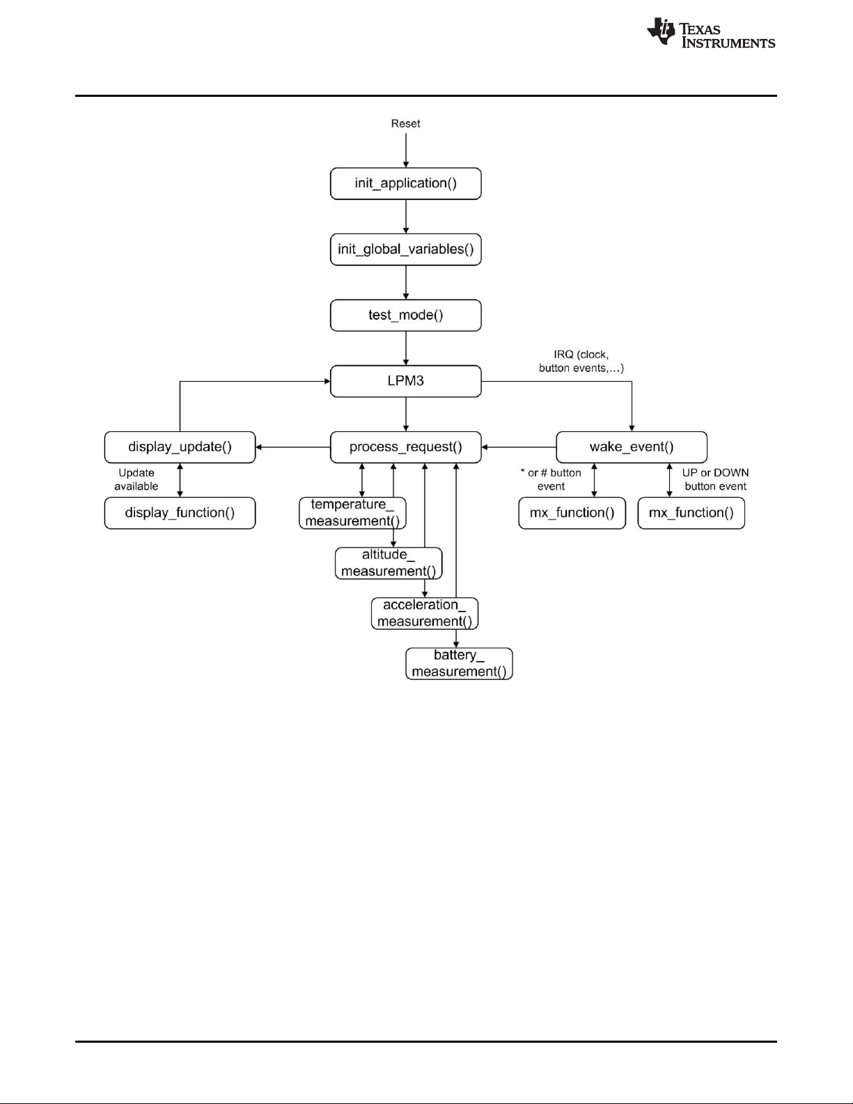
eZ430-Chronos Software Projects
www.ti.com
42
Figure 3-12. eZ430-Chronos Software Flowchart
After a power-up reset, the hardware is initialized, the display memory is cleared and the radio is set to
sleep mode. The main loop waits for wake-up events, which can be either a scheduled event such as a
clock interrupt, or a button event.
Button events lead to the execution of either mx_functions or sx_functions.
If the LCD is updated with new data, the modules set a display flag, and LCD Line1, Line2, or both are
updated by calling the menu-specific display functions. Display updates have been reduced as much as
possible; for example, when the time changes from 10:22 to 10:23, only the last digit is updated.
eZ430-Chronos Software SLAU292F–November 2009–Revised October 2013
Copyright © 2009–2013, Texas Instruments Incorporated
Submit Documentation Feedback
Page 43

www.ti.com
3.6.3 eZ430-Chronos Wireless Update Feature
The wireless update feature allows to perform a firmware update of the eZ430-Chronos wrist module
wirelessly, that is the Chronos module does not need to be opened. The wireless update software should
be seen as an application and not as an universal BSL. It can only be invoked by the main application,
which needs to be created in a certain way (see Section 3.6.3.2). In addition it may must be modified to
comply local RF regulatory. The current consumption during the update process may be significant.
Considering the small battery capacity, the update software is intended to be used only occasionally.
NOTE: References in the software projects and the menu items of the Chronos module refer to it as
"RF BSL" and "WBSL" for simplicity reasons.
Whenever the wireless update is activated on the Chronos module, it returns to the main
application with a reset, wether or not an update was performed. Time, data, alarm, and
other RAM-based data are lost.
3.6.3.1 Overview and Components of the Wireless Update Feature
As described in Section 3.6.3, the wireless update feature allows wireless updates of the eZ430-Chronos
firmware. One of the requirements for the wireless update implementation is to use as little flash memory
as possible. Therefore, a lightweight radio protocol was developed, which resides in the BSL flash area of
the CC430. The software that handles the LCD progress information and the flash memory programming
is downloaded over the air and executed in RAM. Components of the wireless update software include:
• Radio protocol in BSL memory area of the CC430 (eZ430-Chronos wrist module)
• The "RAM-based update software" contains LCD and flash write routines (transferred from PC to RAM
of the wrist module)
• Radio protocol stack of the wireless update on RF access point (CC1111 or MSP430F5509 + CC1101)
• PC application supporting the update functionality
The update procedure works as follows:
1. Wireless update functionality is activated in the PC application, after a valid flash image is selected
2. RF access point is ready and awaits a request from a Chronos module
3. Wireless update is activated on the Chronos module
4. Chronos module downloads LCD and flash write routines (RAM-based update software) from the PC
into the RAM of the CC430. The Chronos module displays "rAN" (=RAM).
5. Chronos module executes the RAM-based update software. This starts the actual code (flash image)
download process. The LCD shows the progress.
6. A reset starts the new application on the Chronos module when the update is finished.
The FAQ in Appendix A also list common questions on the wireless update feature.
eZ430-Chronos Software Projects
3.6.3.2 Detailed Description of the Wireless Update Feature
To invoke the wireless update procedure, the main application must call the start of the wireless update
software, which is located at address 0x1000. Therefore, the demo and data logger projects contain an
extra menu item called "rFbSL". When activated, it determines if the battery level of the Chronos module is
sufficient to start a wireless update and then calls address 0x1000. At this time, the user application is no
longer running.
NOTE: Whenever the wireless update is activated on the Chronos module, it returns to the main
application with a reset, whether or not an update was performed. Time, data, alarm, and
other RAM-based data is lost.
SLAU292F–November 2009–Revised October 2013 eZ430-Chronos Software
Submit Documentation Feedback
Copyright © 2009–2013, Texas Instruments Incorporated
43
Page 44

eZ430-Chronos Software Projects
After invoking the wireless update (rFbSL), the Chronos module tries to link to a listening RF access point
and start the update procedure. If the link is successful, the Chronos module downloads the RAM-based
update software into the RAM of the CC430. Once finished, this software then tries to link again with the
RF access point to download the actual update image. If this link is successful, a mass flash erase is
performed, which erases all the main memory flash (0x8000 to 0xFFFF). The Chronos module then starts
to receive all of the data packets and writes them to flash, checking if each word was written successfully.
If the link is not successful, the Chronos module generates a reset to restart the user application. During
the download of the update image, a percentage indicator appears on the Chronos module. When
download is complete, "dOnE" is shown on the LCD, and a reset is generated to start the new user
application that has just been written to flash.
A detailed flow of the update software on the Chronos module and the USB access point can be found in
Figure 3-13 and Figure 3-14.
www.ti.com
44
Figure 3-13. Flow Chart of Wireless Update Software on Access Point
eZ430-Chronos Software SLAU292F–November 2009–Revised October 2013
Copyright © 2009–2013, Texas Instruments Incorporated
Submit Documentation Feedback
Page 45

www.ti.com
eZ430-Chronos Software Projects
Figure 3-14. Flow Chart of Flash Based Wireless Update Software on eZ430-Chronos Wrist Module
3.6.3.3 Error Handling
The wireless update software is designed to be fail safe. The radio protocol contains limited error handling
due to its small footprint, but the update software provides recovery if the update process fails. Upon
communication failures, the Chronos module is put in low-power mode (LPM4) and the LCD is turned off.
The update process can be restarted by pushing the DOWN button after the update process is restarted
on the PC.
SLAU292F–November 2009–Revised October 2013 eZ430-Chronos Software
Submit Documentation Feedback
Copyright © 2009–2013, Texas Instruments Incorporated
45
Page 46

eZ430-Chronos Software Projects
3.6.3.4 Upgrading Existing eZ430-Chronos Kits
Earlier eZ430-Chronos kits (production date prior to 04/2010; the production date may be found on bottom
of eZ430-Chronos box) do not support the wireless update feature. Therefore, the kits must be updated
manually. In addition to a new version of the PC software, firmware updates of the RF access point and
the eZ430-Chronos wrist module are required.
3.6.3.4.1 RF Access Point Update
3.6.3.4.1.1 Access Point Based on MSP430F5509 Microcontroller and CC1101 Transceiver
The eZ430 USB emulator provided with the Chronos WHITE kit can be used to reprogram the access
point.
1. As shown in Figure 3-15, solder the 4-pin debugger connector (provided with the kit) onto the access
point.
www.ti.com
46
Figure 3-15. Upgrade AP Firmware
2. Connect the eZ430 USB emulator to the access point and then to a PC.
3. Launch an IDE (Code Composer Studio or IAR Embedded Workbench).
4. Select and download the corresponding firmware (default directory: C:\Program Files\Texas
Instruments\eZ430-Chronos\Software Projects\RF Access Point\MSP430 v1.1 - white PCB\CCS ) as
described in Section 3.6.4 .
eZ430-Chronos Software SLAU292F–November 2009–Revised October 2013
Copyright © 2009–2013, Texas Instruments Incorporated
Submit Documentation Feedback
Page 47

www.ti.com
3.6.3.4.1.2 Access Point Based on CC1111
The CC Debugger is required to program the CC1111 based RF access point. To perform the update, the
SmartRF Flash Programmer software is used to on the PC.
1. Solder a debug interface connector cable onto the CC1111 access point as shown in Figure 3-16.
Figure 3-16. eZ430-Chronos RF Access Point Connection to CC Debugger
CC-Debugger RF Access Point
Pin 1 GND
Pin 2 Vcc
Pin 3 P2.2 (DC)
Pin 4 P2.1 (DD)
Pin 7 RST
Pin 9 Vcc
eZ430-Chronos Software Projects
2. Connect RF access point to CC Debugger and press the "Reset". The LED on the CC Debugger
should become green.
3. Launch the SmartRF Programmer software
4. Open .hex file according to frequency in C:\Program Files\Texas Instruments\eZ430-
Chronos\Recovery\RF Access Point
5. Select "Erase, program and verify"
6. Clock "Perform actions"
SLAU292F–November 2009–Revised October 2013 eZ430-Chronos Software
Submit Documentation Feedback
Copyright © 2009–2013, Texas Instruments Incorporated
47
Page 48
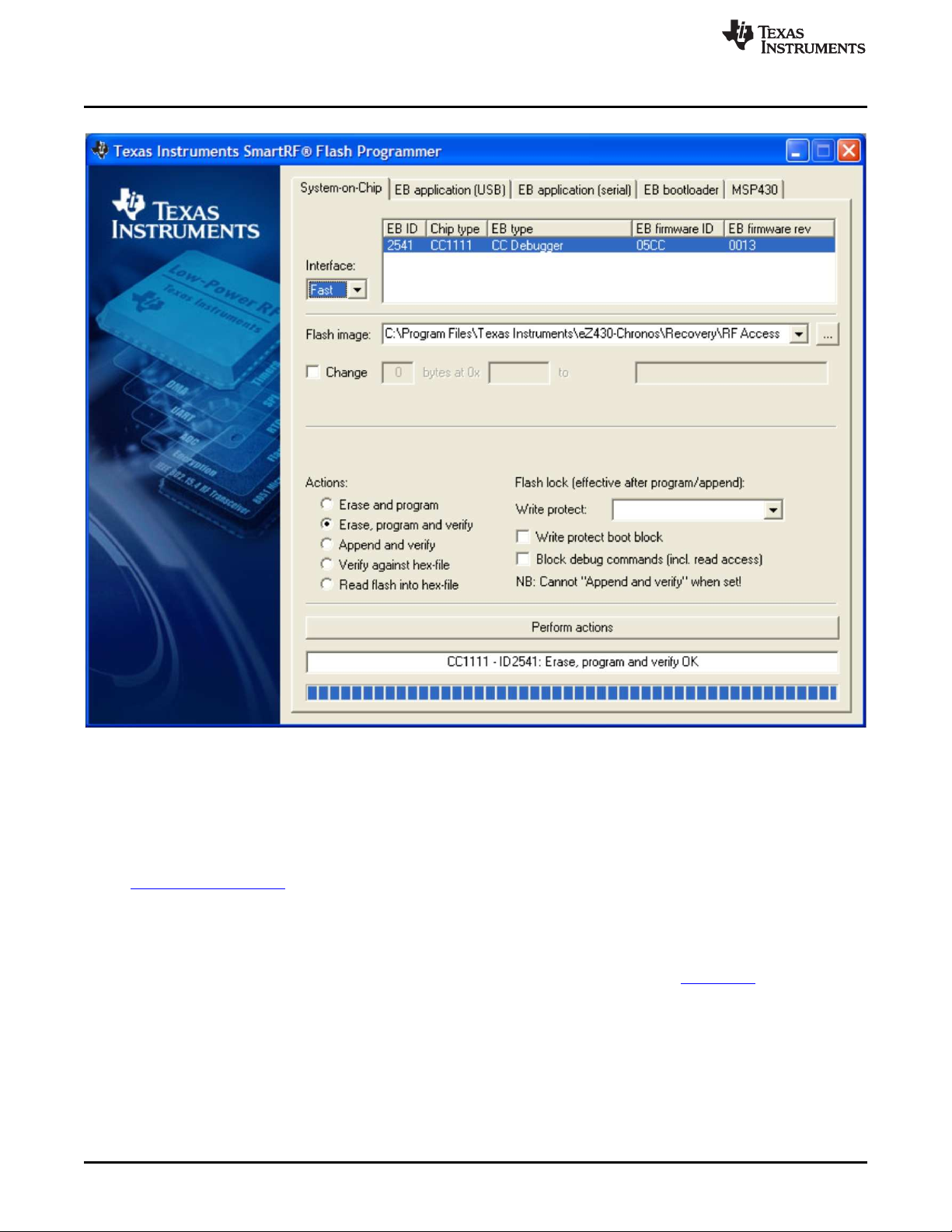
eZ430-Chronos Software Projects
www.ti.com
Figure 3-17. SmartRF Flash Programmer
3.6.3.4.2 eZ430-Chronos Wrist Module Update
The update of the eZ430-Chronos wrist module needs to be done in two stages. First, the wireless update
software needs to be written to the BSL area of the flash memory of the CC430. Afterwards, the main
application must be loaded onto the wrist module. The easiest and fasted way is using BM innovations'
Firmware Update Tool. It writes the wireless update software into the BSL memory of the wrist module
and programs the corresponding demo firmware according to the latest eZ430-Chronos software release
(recommended).
Alternatively, the wireless update software may be loaded onto the wrist module using the included IAR
Embedded Workbench (free KickStart version is sufficient). Moreover, the .txt image may be written to the
device by using 3rd party tools such as the free FET-Pro430 Lite software from Elprotronic.
48
eZ430-Chronos Software SLAU292F–November 2009–Revised October 2013
Copyright © 2009–2013, Texas Instruments Incorporated
Submit Documentation Feedback
Page 49

www.ti.com
3.6.3.4.2.1 eZ430-Chronos Wrist Module Update Using IAR
The project is available in C:\Program Files\Texas Instruments\eZ430-Chronos\Software Projects\Chronos
Watch\IAR\Wireless Update. The eZ430-Chronos module needs to be connected to the emulator which
must be connected to the PC.
1. Open project by double clicking "Wireless Updater.eww"
2. Select build configuration according to frequency in Project > Edit Configurations...
3. Click Project > Download and Debug
4. Close the Embedded Workbench after code was written
5. Program the wrist module main application as described in Section 3.6.4.
3.6.4 eZ430-Chronos Firmware
To restore or modify the original Chronos module projects, the source code must be installed. This
happens during the installation of the demo software package (SLAC341), which contains two different
sets of examples. Code Composer Studio v5.5 or the IAR Workbench can be used, regardless if code
limited or not.
3.6.4.1 Using Code Composer Studio™ v5.5
1. Launch Code Composer Studio v5.5: Start > All Programs > Texas Instruments > Code Composer
Studio 5.5.0 > Code Composer Studio 5.5.0
2. Create new Workspace or open existing Workspace that does not yet contain eZ430-Chronos projects
eZ430-Chronos Software Projects
NOTE: Workspaces should not be located in a long path of directories as Windows only supports
path names up to 255 characters. Keep in mind that the projects contain subdirectories as
well.
3. Import eZ430-Chronos Projects by clicking: Project > Import Existing CCS Eclipse Project
4. Click Browse and browse to eZ430-Chronos Projects (C:\Program Files\Texas Instruments\eZ430-
Chronos\Software Projects\Chronos Watch\CCS ). Confirm directory by clicking OK
5. The eZ430-Chronos demo project appears as ez430_chronos, the eZ430-Chronos data logger
appears as ez430_chronos_datalogger. Check the boxes Copy projects into workspace and
Automatically import referenced projects to create a new copy of the projects
6. Click Finish to finalize the project import. The projects appear in the C/C++ Projects view of CCS
7. Select the right version of the project. Each project comes with six different project settings (build
configurations), which can be selected in Project > Properties > C/C++ Build > Active Configuration >
Configuration:
915 MHz – Limited CCS Core Edition (USA)
868 MHz – Limited CCS Core Edition (Europe)
433 MHz – Limited CCS Core Edition (Other regions)
915 MHz – Unrestricted CCS Platinum (USA)
868 MHz – Unrestricted CCS Platinum (Europe)
433 MHz – Unrestricted CCS Platinum (Other regions)
8. Go to Run > Debug to launch the debugger
SLAU292F–November 2009–Revised October 2013 eZ430-Chronos Software
Submit Documentation Feedback
Copyright © 2009–2013, Texas Instruments Incorporated
49
Page 50

eZ430-Chronos Software Projects
3.6.4.2 Using IAR Embedded Workbench™
1. Launch the Embedded Workbench:Start > All Programs > IAR Systems > IAR Embedded Workbench
KickStart for MSP430 5.60 > IAR Embedded Workbench
2. Open eZ430-Chronos Workspace by: File > Open > Workspace...
3. Browse to eZ430-Chronos Projects (C:\Program Files\Texas Instruments\eZ430-Chronos\Software
Projects\Chronos Watch\IAR\Sports Watch or C:\Program Files\Texas Instruments\eZ430Chronos\Software Projects\Chronos Watch\IAR\Data Logger)
4. Select *.eww file and click Open
5. Select the right version of the project. Each project comes with four different project settings (build
configurations), which can be selected on top of the Workspace window:
915 MHz – Limited IAR KickStart (USA)
868 MHz – Limited IAR KickStart (Europe)
433 MHz – Limited IAR KickStart (Other regions)
915 MHz – Unrestricted IAR Workbench (USA)
868 MHz – Unrestricted IAR Workbench (Europe)
433 MHz – Unrestricted IAR Workbench (Other regions)
6. Go to Project > Download and Debug to launch the debugger
3.6.5 eZ430-Chronos GUI Sources
Full sources of the eZ430-Chronos Control Center and eZ430-Chronos Data Logger are available in the
eZ430-Chronos software packages for Windows SLAC341 and Linux SLAC388. The sources are copied
to the PC during the software installation. The graphical user interfaces are based on TCL/Tk.
www.ti.com
3.6.5.1 eZ430-Chronos GUI for Windows
The eZ430-Chronos PC software consists of a TCL/Tk executable and a DLL, which handles the
communication with the RF access Point. Download TCL/Tk for Windows for free from
http://www.activestate.com/activetcl. Once TCL/Tk was installed on the computer, a double-click on a TCL
script (*.tcl) starts the interpreter and executes the script. Alternatively, start the TCL interpreter wish.exe
and execute the script with the "source" command. If the script filename contains blanks, put it into quotes.
The sources files are located in C:\Program Files\Texas Instruments\eZ430-Chronos\Control Center\GUI
Sources
3.6.5.1.1 TCL/TK Handling
A wrapping tool is needed to compile all TCL/Tk components into standalone applications. The freeware
tool Freewrap http://freewrap.sourceforge.net may be used for that purpose.
1. Open Command Prompt
2. Navigate to the Freewrap directory; for example, C:\Tcl\freewrap
3. Start Freewrap with the complete path to the TCL script to be wrapped; for example, freewrap.exe
C:\Program Files\Texas Instruments\eZ430-Chronos\Control Center\eZ430-Chronos Control
Center\eZ430-Chronos CC 1_2.tcl
A standalone application, which only requires the corresponding Windows DLL is generated. It can be
used on every PC, TCL/Tk must not be installed.
50
eZ430-Chronos Software SLAU292F–November 2009–Revised October 2013
Copyright © 2009–2013, Texas Instruments Incorporated
Submit Documentation Feedback
Page 51

www.ti.com
3.6.5.1.2 Control Center DLL
The sources for the DLL are available in the eZ430-Chronos Windows package and can be found in
C:\Program Files\Texas Instruments\eZ430-Chronos\Control Center\GUI Sources\DLL.
The eZ430-Chronos Windows DLL has been developed using Microsoft Visual C++ 2008 Express Edition.
In order to rebuild the DLL file the Microsoft Visual Studio must be installed, since the registry enumeration
code uses MFC functions. If Microsoft Visual Studio is not present, it is still possible to rebuild the DLL, but
the "enumser" source code part needs to be removed from the project. Therefore, the BM_GetCOM()
function won’t work anymore.
The DLL has two interface sections, one that exports standard C functions, and a second one exporting
TCL-compliant functions. These TCL-compliant functions are used by the graphical user interface. Hence,
when compiling the DLL, TCL needs to be present in the default directory (C:\Tcl); otherwise, the
reference to the TCL libraries (tcl85.lib, tclstub85.lib) is invalid. If the DLL is compiled without the TCL
interface, the respective source code file and the references to the TCL libraries must be deleted.
COM Port Management
1. Opening the COM port
Prior to any communication, the COM port where the RF access point is connected must be opened.
The hardware is powered up immediately after the unit is connected. Some parts of the hardware
require a startup time of several hundred milliseconds. As a result, any access to the hardware should
not be done within one second after connecting the device.
NOTE: To address COM ports higher than COM9 in Windows, precede the "COMxx" string with the
sequence "\\.\".
eZ430-Chronos Software Projects
The COM port is opened with the following function:
bool BM_OpenCOM( char * strPortName,
DWORD dwBaudrate = 115200,
WORD wTimeout = 30,
bool bRTS = false,
bool bDTR = false);
Parameters
strPortName
Name of the COM port (for example, "\\.\COM11").
wTimeout
Time in milliseconds a reply to a command is expected; default value is 30 ms, should not be
changed
dwBaudrate
Baudrate for the serial interface; default is 115200 Baud, should not be changed
bRTS
State of RTS line during normal operation; default is false (=GND), should not be changed
bDTR
State of DTR line during normal operation; default is false (=GND), should not be changed
Return Value
Returns true if COM port could be opened, otherwise returns false.
2. Closing the COM port
A successfully opened COM port must be closed when quitting the application to release all allocated
memory and the port itself.
The COM port is closed with the following function:
void BM_CloseCOM(void);
SLAU292F–November 2009–Revised October 2013 eZ430-Chronos Software
Submit Documentation Feedback
Copyright © 2009–2013, Texas Instruments Incorporated
51
Page 52

eZ430-Chronos Software Projects
3. Locating the RF access point
This function checks the Windows registry for the friendly name "TI CC1111 Low-Power RF to USB
CDC Serial Port" or "eZ430-ChronosAP" and returns the COM port number if the device was found.
bool BM_GetCOM(unsigned char& bPortNb);
Parameters
bPortNb
Number of the COM port (for example, „11")
Return Value
Returns true if device was found, otherwise returns false.
4. Resetting the RF access point
After power-up, the hardware is not automatically reset. Use the following function to initialize the RF
access point hardware. This function can also be used during normal operation if an error condition
was detected.
bool BM_Reset(void);
Return Value
Returns true if RF access point could be initialized successfully and false if the reset failed.
5. Read status from RF access point
This command returns the current RF access point status.
bool BM_GetStatus(WORD& wStatus);
Parameters
wStatus
Current status of RF access point HW_IDLE, HW_SIMPLICITI_STOPPED,
HW_SIMPLICITI_TRYING_TO_LINK, HW_SIMPLICITI_LINKED, HW_BLUEROBIN_STOPPED,
HW_BLUEROBIN_TRANSMITTING, HW_ERROR, HW_NO_ERROR, HW_NOT_CONNECTED
Return Value
Returns true if command could be executed and false if the command execution failed.
BlueRobin Functions
1. Set BlueRobin Heart Rate
This command sets the heart rate value that is transmitted in each BlueRobin packet.
bool BM_BR_SetHeartrate(WORD wHeartrate);
Parameters
wHeartrate
Heart rate in bpm
Return Value
Returns true if command could be executed and false if the command execution failed.
2. Set BlueRobin ID
This command sets the transmitter ID for BlueRobin transmission.
bool BM_BR_SetID(DWORD dwID);
Parameters
dwID
24-bit transmitter ID
Return Value
Returns true if command could be executed and false if the command execution failed.
www.ti.com
52
eZ430-Chronos Software SLAU292F–November 2009–Revised October 2013
Copyright © 2009–2013, Texas Instruments Incorporated
Submit Documentation Feedback
Page 53

www.ti.com
3. Read BlueRobin ID
4. Start BlueRobin transmission
5. Stop BlueRobin transmission
SimpliciTI Functions
1. Start SimpliciTI in acc/ppt mode
2. Start SimpliciTI in sync mode
3. Stop SimpliciTI
eZ430-Chronos Software Projects
This command reads the transmitter ID for BlueRobin transmission.
bool BM_BR_GetID(DWORD& dwID);
Parameters
dwID
24-bit transmitter ID
Return Value
Returns true if command could be executed and false if the command execution failed.
This command starts the BlueRobin transmission.
bool BM_BR_Start(void);
Return Value
Returns true if command could be executed and false if the command execution failed.
This command stops the BlueRobin transmission.
bool BM_BR_Stop(void);
Return Value
Returns true if command could be executed and false if the command execution failed.
This command starts SimpliciTI in acc/ppt mode.
bool BM_SPL_Start(void);
Return Value
Returns true if command could be executed and false if the command execution failed.
This command starts SimpliciTI in sync mode.
bool BM_SYNC_Start(void);
Return Value
Returns true if command could be executed and false if the command execution failed.
This command exits the SimpliciTI stack.
bool BM_SPL_Stop(void);
Return Value
Returns true if command could be executed and false if the command execution failed.
SLAU292F–November 2009–Revised October 2013 eZ430-Chronos Software
Submit Documentation Feedback
Copyright © 2009–2013, Texas Instruments Incorporated
53
Page 54

eZ430-Chronos Software Projects
4. Read SimpliciTI acc/ppt data
This command reads the received data from the RF access point buffer.
bool BM_SPL_GetData(DWORD& wData);
Parameters
wData
4 byte data (byte3, byte2, byte1, byte0)
byte3 = Acceleration value Z-axis
byte2 = Acceleration value Y-axis
byte1 = Acceleration value X-axis
byte0 = 0x11 → Left mouse click (acc mode)
byte0 = 0x21 → Left mouse double-click (acc mode)
byte0 = 0x31 → Right mouse click (acc mode)
byte0 = 0x12 → Button * (ppt mode)
byte0 = 0x22 → Button # (ppt mode)
byte0 = 0x32 → Button ↑ (ppt mode)
byte0 = 0xFF → Data has been read before
Return Value
Returns true if command could be executed and false if the command execution failed.
5. Read SimpliciTI sync buffer status
This command reads the buffer status during sync mode from the RF access point buffer.
bool BM_SYNC_GetBufferStatus(WORD& wStatus);
Parameters
wStatus
Buffer status
0 = Buffer empty
1 = Data available for download
Return Value
Returns true if command could be executed and false if the command execution failed.
6. Read SimpliciTI sync buffer
This command reads the buffer content during sync mode.
bool BM_SYNC_ReadBuffer(BYTE * bData);
Parameters
bData
19-byte SimpliciTI data Packet content defined Chronos module sending routine
Return Value
Returns true if command could be executed and false if the command execution failed.
Wireless Update Functions
1. Start wireless update
This command starts SimpliciTI in acc/ppt mode.
BR_COMM_API bool BM_WBSL_Start(void)
Return Value
Returns true if command could be executed and false if the command execution failed.
2. Stop wireless update
This command exits the SimpliciTI stack.
BR_COMM_API bool BM_WBSL_Stop(void)
Return Value
Returns true if command could be executed and false if the command execution failed.
www.ti.com
54
eZ430-Chronos Software SLAU292F–November 2009–Revised October 2013
Copyright © 2009–2013, Texas Instruments Incorporated
Submit Documentation Feedback
Page 55

www.ti.com
3. Get status of update
4. Send Data (Text File parts) to the End Device
5. Get status of packet (checks if a new packet needs to be sent from the GUI)
eZ430-Chronos Software Projects
This command reads the buffer status during sync mode from the RF access point buffer.
BR_COMM_API bool BM_WBSL_GetStatus(DWORD& wData)
Parameters
dwData
Status
1 = linking
2 = linked
4 = error
Return Value
Returns true if command could be executed and false if the command execution failed.
This command reads the buffer status during sync mode from the RF access point buffer.
BR_COMM_API bool BM_WBSL_Send_Data(BYTE * data, int len, DWORD& dwData)
Parameters
data
Pointer to byte array
len
Array length
dwData
Return value
Return Value
dwData = Length of last transmitted package.
This command reads the buffer status during sync mode from the RF access point buffer.
BR_COMM_API bool BM_WBSL_GetPacketStatus(DWORD& wData)
Return Value
dwData
0x80 = error
0x01 = disabled
0x02 = processing packet
0x04 = send info packet
0x08 = send new data packet
3.6.5.2 eZ430-Chronos GUI for Linux
The eZ430-Chronos PC software for Linux consists of a TCL/Tk scrips, similar to its Windows equivalent.
The scripts are available in/home/<user name>/Texas Instruments/eZ430-Chronos/Control Center/eZ430-
Chronos Control Center.
See Section 3.3 for instructions on how to run these scripts on Linux machines.
SLAU292F–November 2009–Revised October 2013 eZ430-Chronos Software
Submit Documentation Feedback
Copyright © 2009–2013, Texas Instruments Incorporated
55
Page 56

Chapter 4
SLAU292F–November 2009–Revised October 2013
eZ430-Chronos Hardware
4.1 Programming the eZ430-Chronos Wrist Module: Disassembly and Assembly of the Housing
To program and debug code on the CC430, it needs to be connected to a PC with a JTAG interface. The
eZ430-Chronos kit includes the eZ430-RF JTAG interface for that purpose. It can only be connected to the
eZ430-Chronos module after the electronic module is removed from its housing. This chapter describes
how to remove the electronic module from the housing and how to assemble the wrist module again.
NOTE: Videos with detailed instructions can be found on www.ti.com/chronos and the CD that is
included in the kits.
4.1.1 Disassembly of eZ430-Chronos Wrist Module
1. Open screws on back of the wrist module. Use the included Phillips screwdriver.
2. Remove the metal back of the wrist housing. Be careful not to damage the gasket between the wrist
module and the metal back.
3. Lift out the Chronos module. Use the screwdriver as shown in Figure 4-1.
56
Figure 4-1. Remove Chronos Module From Housing
eZ430-Chronos Hardware SLAU292F–November 2009–Revised October 2013
Copyright © 2009–2013, Texas Instruments Incorporated
Submit Documentation Feedback
Page 57

www.ti.com
4. Remove the battery before connecting the module to the emulator. Place the screwdriver tip between
Programming the eZ430-Chronos Wrist Module: Disassembly and Assembly of the Housing
the battery and the battery holder (small metal tab) and push the tab away from battery (see Figure 4-
2). Detailed instructions are shown in the eZ430-Chronos Disassembly and Assembly video on
www.ti.com/chronoswiki.
Figure 4-2. Remove Chronos Module Battery
CAUTION
To prevent the battery from being charged, always remove the battery from the
enclosure before connecting the Chronos module to an emulator.
WARNING
Properly dispose of the battery. Keep the battery out of the reach
of children. If the battery is swallowed, contact a physician
immediately.
SLAU292F–November 2009–Revised October 2013 eZ430-Chronos Hardware
Submit Documentation Feedback
Copyright © 2009–2013, Texas Instruments Incorporated
57
Page 58
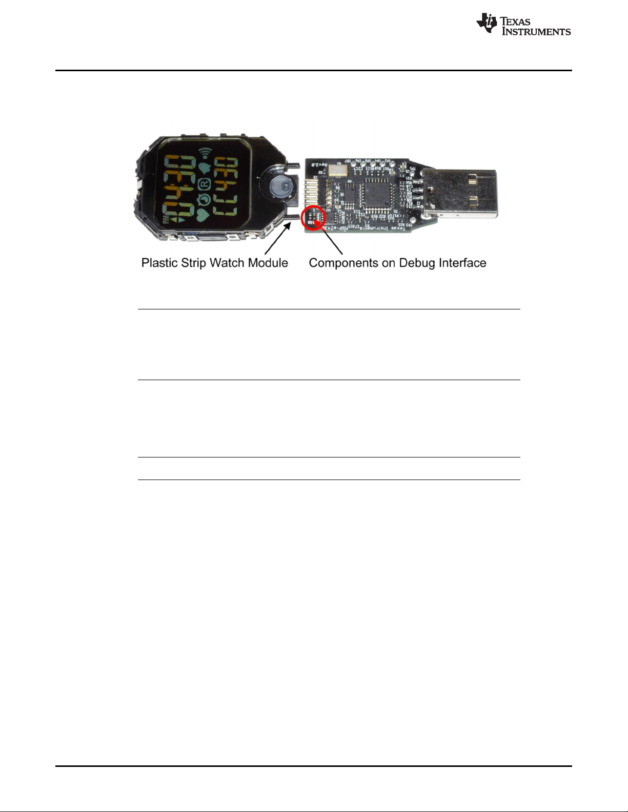
Programming the eZ430-Chronos Wrist Module: Disassembly and Assembly of the Housing
5. Connect the Chronos module to the emulator. The Chronos module and the USB connector must be
on the same side of the PCB as shown in Figure 4-3. Be careful when connecting the Chronos
module, because its small plastic strips can get stuck at components on the emulator.
Figure 4-3. eZ430-Chronos Module Attached to eZ430-RF Debug Interface
NOTE:
• Never disassemble the Chronos module itself.
• Do not bend the metal strips that are used as contacts for the buttons.
• Be careful when connecting the Chronos module to the debug interface; its small plastic
strips can get stuck at components on the emulator.
www.ti.com
4.1.2 Assembly of eZ430-Chronos Wrist Module
1. Insert the battery ("+" facing up) into Chronos module and close battery holder clip by pushing the
open end towards the module. If the small clip at the end of the holder does not snap into the plastic
frame, it may need to be bent inwards slightly
NOTE: Only insert Q-LITE Lithium battery type CR2032 or equivalent.
2. Gently insert Chronos module into the housing. Insert it in parallel to the housing. Do not try to insert
one side first (see Figure 4-4). Ensure that the small metal strips of the buttons on Chronos module
slide over buttons of the housing (see Figure 4-5).
58
eZ430-Chronos Hardware SLAU292F–November 2009–Revised October 2013
Copyright © 2009–2013, Texas Instruments Incorporated
Submit Documentation Feedback
Page 59
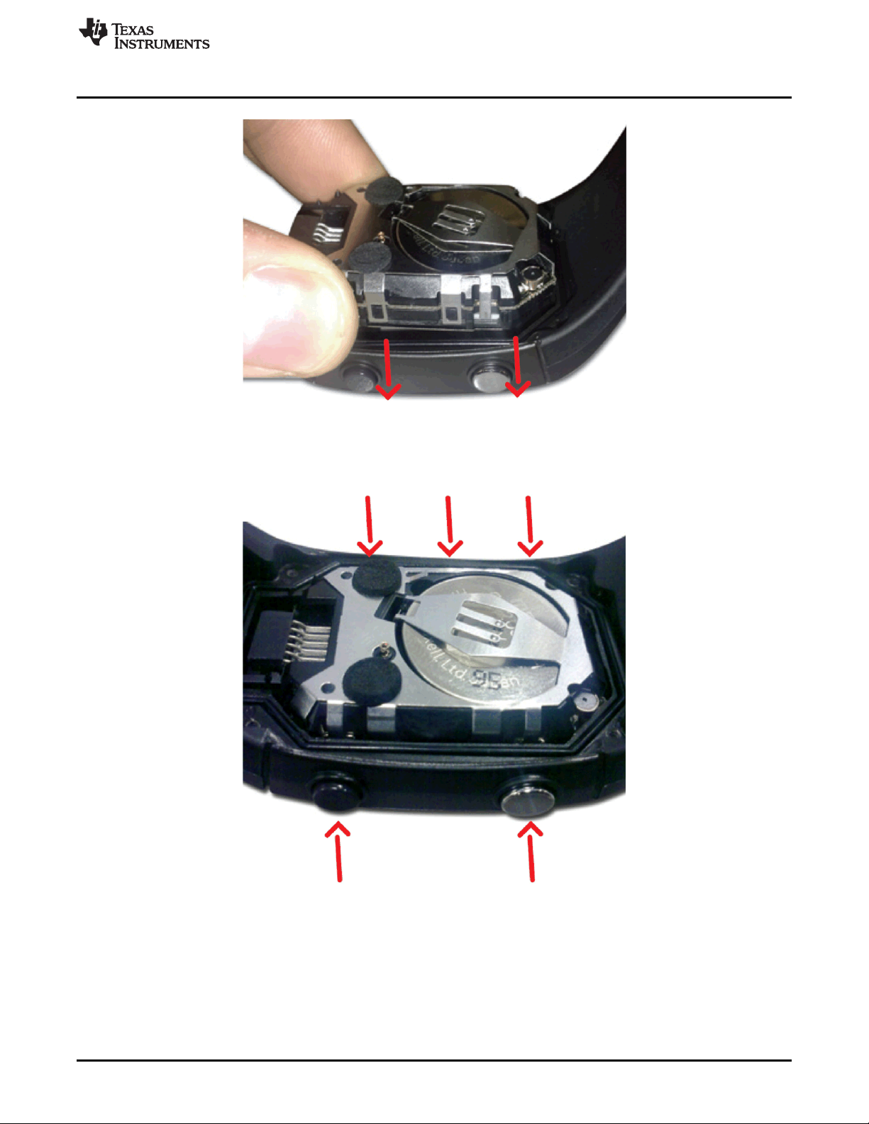
www.ti.com
Programming the eZ430-Chronos Wrist Module: Disassembly and Assembly of the Housing
Figure 4-4. eZ430-Chronos Module Insertion Into Housing
Figure 4-5. Metal Strips of Chronos Module Housing and Buttons of Housing
SLAU292F–November 2009–Revised October 2013 eZ430-Chronos Hardware
Submit Documentation Feedback
Copyright © 2009–2013, Texas Instruments Incorporated
59
Page 60

Functional Description of the eZ430-Chronos Wrist Module
Be careful when inserting the Chronos module. Do not push in the Chronos
module or tighten the screws without checking if the module is in position. The
metal strips of the buttons may get stuck at the buttons of the Chronos module
housing. If this happens, gently push the strips towards the module with the
screwdriver until they slide over the buttons (see Figure 4-6).
www.ti.com
CAUTION
Figure 4-6. Push Metal Strips Inward
3. Make sure that the gasket is in position and replace the back with the screws. Try to use the existing
threads in the plastic housing and do not over tighten the screws.
4.2 Functional Description of the eZ430-Chronos Wrist Module
The core technology behind the eZ430-Chronos wrist module is the CC430F6137 microcontroller with its
integrated <1-GHz radio. The CC430 also controls the LCD and its temperature sensor is used for
temperature measurement. The only other ICs on the Chronos module PCB are pressure and acceleration
sensors and the LCD backlight driver.
60
Figure 4-7. eZ430-Chronos Wrist Module Block Diagram
eZ430-Chronos Hardware SLAU292F–November 2009–Revised October 2013
Copyright © 2009–2013, Texas Instruments Incorporated
Submit Documentation Feedback
Page 61

www.ti.com
The PCB does not include an antenna; the metal frame of the Chronos module that surrounds the LCD is
used as antenna. The antenna is tuned for best performance when the Chronos module is worn or held in
hands.
Functional Description of the eZ430-Chronos Wrist Module
Figure 4-8. eZ430-Chronos Module Front
Figure 4-9. eZ430-Chronos Module Back
Table 4-1. Estimated Battery Life (Demo Software)
Mode Average Current Battery Life
Shelf mode (LPM4) 2.7 µA 92.6 months
Welcome screen (LPM3) 8.9 µA 28.0 months
Time and date 9.0 µA 27.7 months
Continuous temperature measurement 10.0 µA 25.0 months
Continuous altitude measurement 18.0 µA 13.8 months
Continuous acceleration measurement 166.0 µA 1.5 months
Continuous BlueRobin RX 40.0 µA 6.2 months
Continuous SimpliciTI PPT (no button pressed) 10.0 µA 25.0 months
Continuous SimpliciTI SYNC 0.9 mA 8 days
Continuous SimpliciTI ACC 3.7 mA 2 days
1 hour per day BlueRobin RX 10.3 µA 24.2 months
1 hour per day SimpliciTI PPT (no button pressed) 9.1 µA 25.4 months
1 hour per day SimpliciTI SYNC 46.1 µA 5.4 months
1 hour per day SimpliciTI ACC 169.9 µA 1.4 months
SLAU292F–November 2009–Revised October 2013 eZ430-Chronos Hardware
Submit Documentation Feedback
Copyright © 2009–2013, Texas Instruments Incorporated
61
Page 62
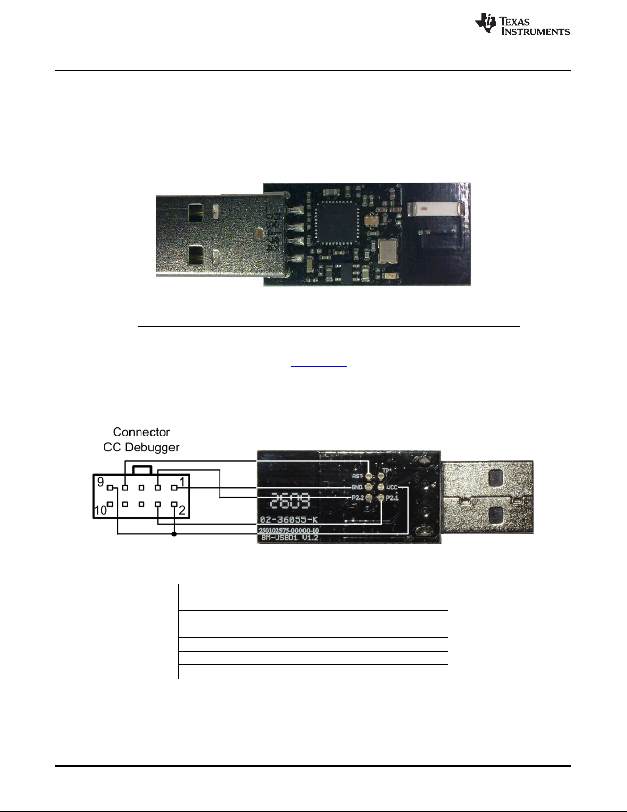
Functional Description of the eZ430-Chronos RF Access Point
4.3 Functional Description of the eZ430-Chronos RF Access Point
The RF access point allows wireless communication with the eZ430-Chronos directly from the PC to
download data, sync information, or control programs running on the PC (see Figure 4-10).
4.3.1 Access Point With Black PCB
This access point is based on the CC1111F32 controller, which features an integrated USB controller in
addition to a <1-GHz radio.
Figure 4-10. eZ430-Chronos RF Access Point
NOTE: The access point is this kit comes in a small production-ready design. Therefore, it does not
include a JTAG connector. However, the bottom side provides pads that allow soldering
cables to connect the CC1111 to the CC Debugger. TI also offers the professional
CC1111EMK868-915 development kit including connectors and a push button.
www.ti.com
To program the RF access point, a debug interface connector cable must be soldered to the CC1111
access point as shown in Figure 4-11.
Figure 4-11. eZ430-Chronos RF Access Point Connection to CC Debugger
CC-Debugger RF Access Point
Pin 1 GND
Pin 2 Vcc
Pin 3 P2.2 (DC)
Pin 4 P2.1 (DD)
Pin 7 RST
Pin 9 Vcc
62
eZ430-Chronos Hardware SLAU292F–November 2009–Revised October 2013
Copyright © 2009–2013, Texas Instruments Incorporated
Submit Documentation Feedback
Page 63
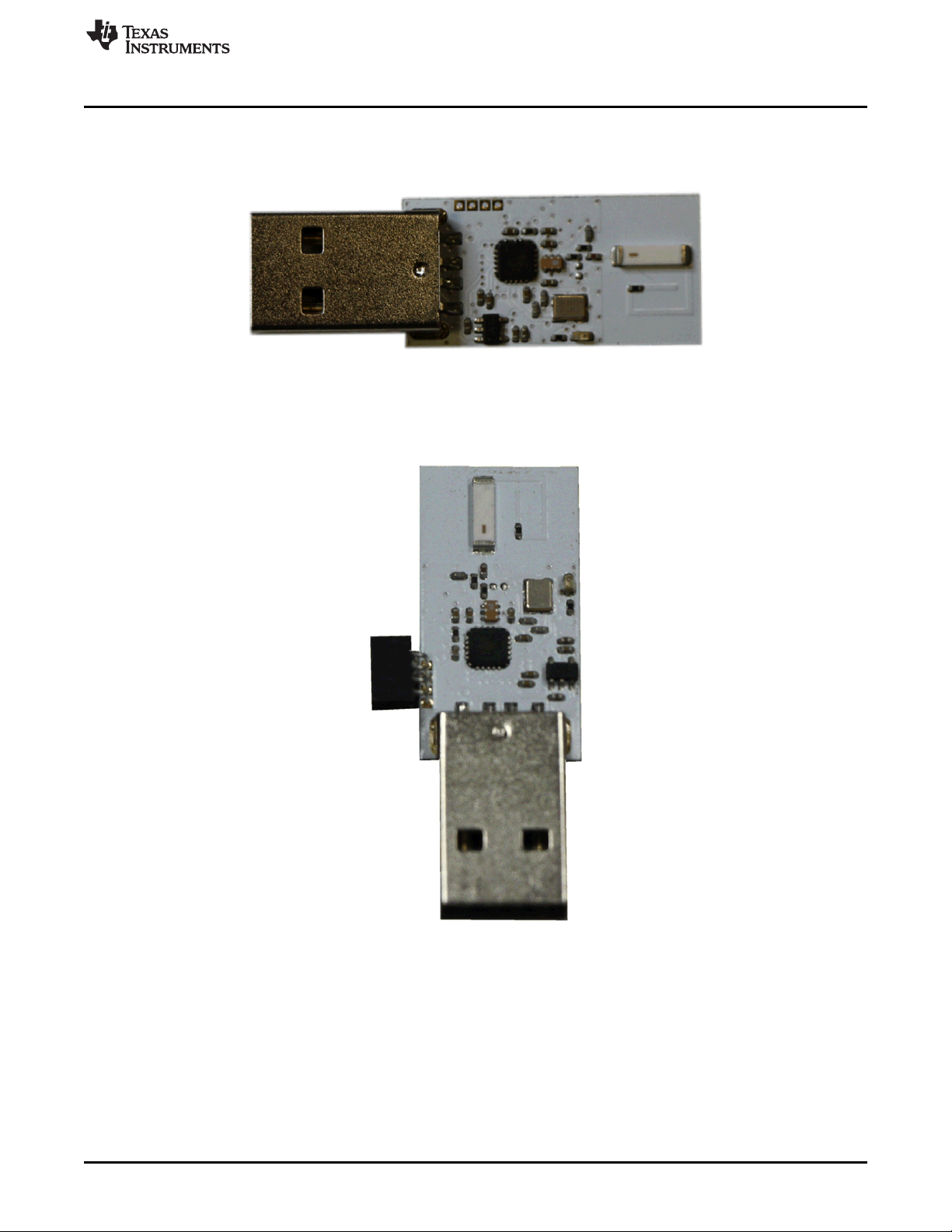
www.ti.com
4.3.2 Access Point With White PCB
This access point consists of an MSP430F5509 microcontroller connected to a <1-GHz transceiver
(CC1101) (see Figure 4-12).
Figure 4-12. Access Point With White PCB
As shown in Figure 3-15, the RF access point can be reprogrammed by connecting the eZ430 USB
emulator to the access point. First of all, solder the 4-pin debugger connector (provided with the kit) onto
the access point.
Functional Description of the eZ430-Chronos RF Access Point
Figure 4-13. Access Point With Connector
SLAU292F–November 2009–Revised October 2013 eZ430-Chronos Hardware
Submit Documentation Feedback
Copyright © 2009–2013, Texas Instruments Incorporated
63
Page 64
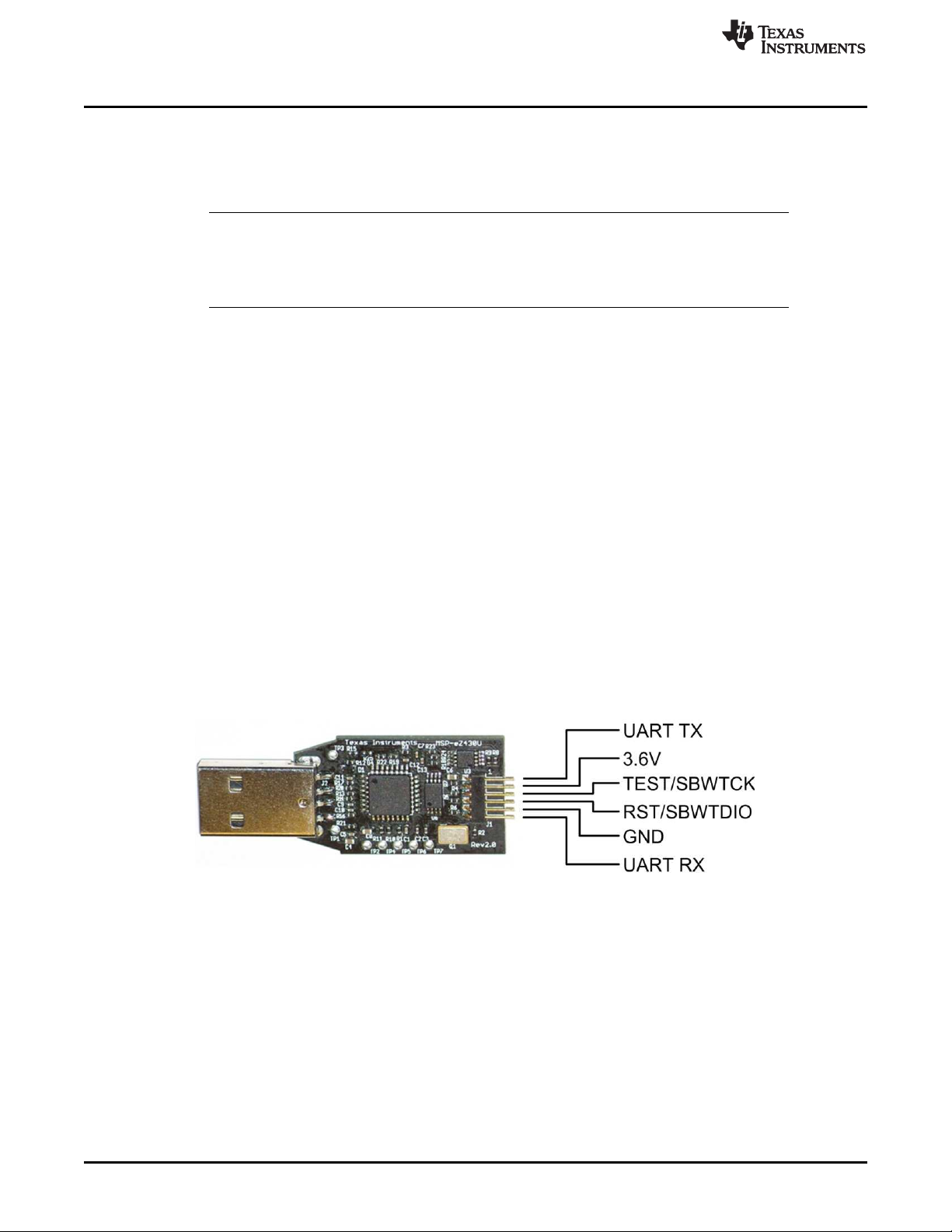
Functional Description of the eZ430-Chronos Debug Interface
4.4 Functional Description of the eZ430-Chronos Debug Interface
The eZ430-Chronos kit includes an USB emulator that provides full programming and debugging features
using its Spy-Bi-Wire (2-wire) interface. It features a back channel MSP430 application UART that may be
used independently of a debug session.
NOTE: The eZ430 USB emulator with white or black PCB are identical from a hardware perspective.
Despite the fact that the Chronos module is equipped with a 6-pin connector, there is no
UART connection from the Chronos module to the emulator as all pins of the CC430 are
already used for other purposes.
Supported devices:
• CC430F51xx
• CC430F61xx
• MSP430F20xx
• MSP430F21x2
• MSP430F22xx
• MSP430F41x2
• MSP430F54xx
• MSP430F54xxA
• MSP430F55xx
Connector J1 on the emulator (starting on top with pin 1) (see Figure 4-14).
• UART TX (from emulator to target)
• 3.6-V supply for target
• TEST/SBWTCK
• RST/SBWTDIO
• GND
• UART RX (from target to emulator)
www.ti.com
Figure 4-14. eZ430-Chronos Debug Interface
4.4.1 MSP430 Application UART
The eZ430-Chronos emulator includes a back channel MSP430 Application UART that may be used
independently of a debug session. This allows the user to transfer serial data to a terminal window at a
fixed rate of 9600 bps with no flow control. Check the Device Manager for COM port assignment of the
MSP430 Application UART (for more details, see Section B.2).
64
eZ430-Chronos Hardware SLAU292F–November 2009–Revised October 2013
Copyright © 2009–2013, Texas Instruments Incorporated
Submit Documentation Feedback
Page 65

www.ti.com
4.5 Schematics, Layout, BOM, and LCD
Gerber files for the eZ430-Chronos wrist module are part of the eZ430-Chronos software packages for
Windows SLAC341 and Linux SLAC388.
4.5.1 eZ430-Chronos-433 Wrist Module With Black PCB
Schematics, Layout, BOM, and LCD
Figure 4-15. eZ430-Chronos-433 Wrist Module With Black PCB, Schematics
SLAU292F–November 2009–Revised October 2013 eZ430-Chronos Hardware
Submit Documentation Feedback
Copyright © 2009–2013, Texas Instruments Incorporated
65
Page 66
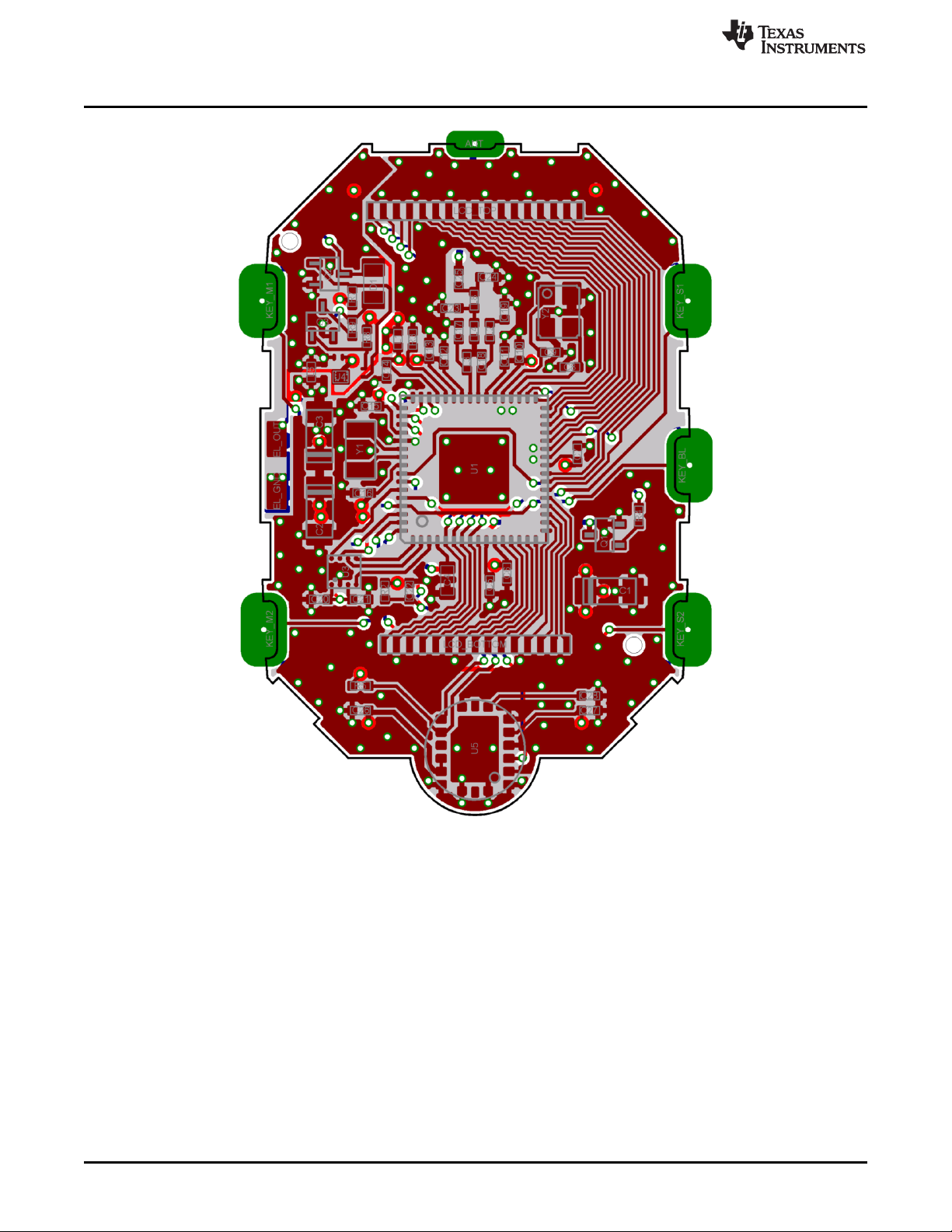
Schematics, Layout, BOM, and LCD
www.ti.com
Figure 4-16. eZ430-Chronos-433 Wrist Module With Black PCB, PCB Components on Top Layer
66
eZ430-Chronos Hardware SLAU292F–November 2009–Revised October 2013
Copyright © 2009–2013, Texas Instruments Incorporated
Submit Documentation Feedback
Page 67
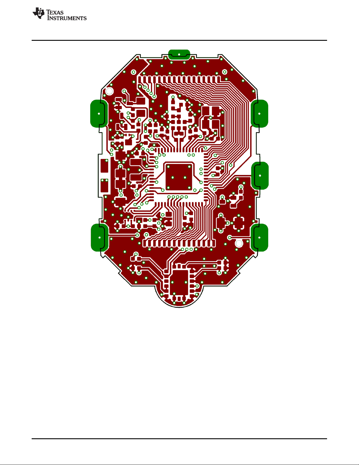
www.ti.com
Schematics, Layout, BOM, and LCD
Figure 4-17. eZ430-Chronos-433 Wrist Module With Black PCB, Layout Top Layer (LCD Side)
SLAU292F–November 2009–Revised October 2013 eZ430-Chronos Hardware
Submit Documentation Feedback
Copyright © 2009–2013, Texas Instruments Incorporated
67
Page 68

Schematics, Layout, BOM, and LCD
www.ti.com
68
Figure 4-18. eZ430-Chronos-433 Wrist Module With Black PCB, Layout Second Layer
eZ430-Chronos Hardware SLAU292F–November 2009–Revised October 2013
Copyright © 2009–2013, Texas Instruments Incorporated
Submit Documentation Feedback
Page 69

www.ti.com
Schematics, Layout, BOM, and LCD
Figure 4-19. eZ430-Chronos-433 Wrist Module With Black PCB, Layout Third Layer
SLAU292F–November 2009–Revised October 2013 eZ430-Chronos Hardware
Submit Documentation Feedback
Copyright © 2009–2013, Texas Instruments Incorporated
69
Page 70
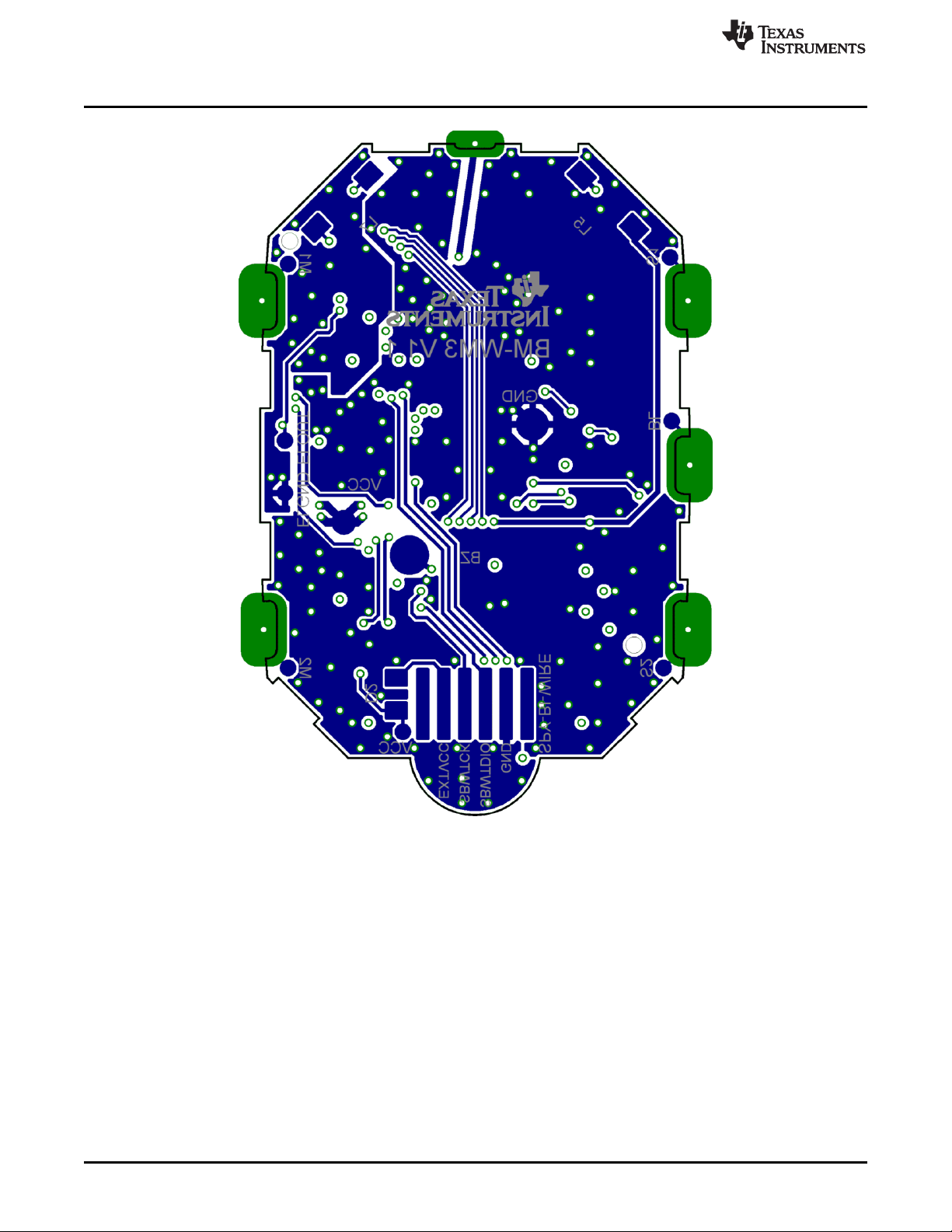
Schematics, Layout, BOM, and LCD
www.ti.com
Figure 4-20. eZ430-Chronos-433 Wrist Module With Black PCB, Layout Bottom Layer (Battery Side)
70
eZ430-Chronos Hardware SLAU292F–November 2009–Revised October 2013
Copyright © 2009–2013, Texas Instruments Incorporated
Submit Documentation Feedback
Page 71

www.ti.com
Schematics, Layout, BOM, and LCD
Table 4-2. eZ430-Chronos-433 Wrist Module With Black PCB, BOM List
Designator Value Tolerance Footprint Description Manufacturer
C1 47 µF ±20% TAJ-A Capacitor SMD Tantalum, height max. 1.6 mm
C2 47 µF ±20% TAJ-A Capacitor SMD Tantalum, height max. 1.6 mm
C3 47 µF ±20% TAJ-A Capacitor SMD Tantalum, height max. 1.6 mm
C4 4.7 µF ±20%, X5R 603 Capacitor SMD
C5 470 nF ±10%, X5R 402 Capacitor SMD
C6 100 nF ±10%, X7R 402 Capacitor SMD
C7 100 nF ±10%, X7R 402 Capacitor SMD
C8 15 pF ±5%, COG/NP0 402 Capacitor SMD
C9 15 pF ±5%, COG/NP0 402 Capacitor SMD
C10 10 nF ±10%, X7R 402 Capacitor SMD
C11 2.2 pF ±0.25 pF, COG/NP0 402 Capacitor SMD
C12 10 nF ±10%, X7R 402 Capacitor SMD
C13 220 pF ±10%, COG/NP0 402 Capacitor SMD
C14 100 nF ±10%, X7R 402 Capacitor SMD
C15 100 nF ±10%, X7R 402 Capacitor SMD
C16 100 nF ±10%, X7R 402 Capacitor SMD
C17 3.9 pF ±0.1 pF, COG/NP0 402 Capacitor SMD Johanson 500R07S3R9BV4
C18 3.9 pF ±0.1 pF, COG/NP0 402 Capacitor SMD Johanson 500R07S3R9BV4
C19 220 pF ±10%, COG/NP0 402 Capacitor SMD
C20 100 nF ±10%, X7R 402 Capacitor SMD
C21 100 nF ±10%, X7R 402 Capacitor SMD
C22 2.2 nF ±10%, X7R 402 Capacitor SMD
C26 470 nF ±10%, X5R 402 Capacitor SMD
C27 470 nF ±10%, X5R 402 Capacitor SMD
C28 100 nF ±10%, X7R 402 Capacitor SMD
D1 1N4148 805 Diode SMD
D2 1N4148 805 Diode SMD
L1 12 nH ±5% 402 Inductor Monolithic SMD Johanson L-07C12NJV4
L2 27 nH ±5% 402 Inductor Monolithic SMD Johanson L-07C27NJV4
L3 27 nH ±5% 402 Inductor Monolithic SMD Johanson L-07C27NJV4
L4 4.7 nH ±0.3nH 402 Inductor Monolithic SMD Johanson L-07C4N7SV4
L5 RDC≤250Ω, ±10% Inductor Coil
L6 100 nH ±10% 402 Inductor Monolithic SMD
L7 ±10% Inductor Coil
L8 18 nH ±5% 402 Inductor Monolithic SMD Johanson L-07C18NJV4
P1 Connector SMD for example, MPE-Garry BL SMD 91-06
PCB1
Q1 SOT323
Q2 SOT323
Q3 SOT323
R2 47k ±5% 402 Resistor SMD
R3 56k ±1% 402 Resistor SMD
R4 47k ±5% 402 Resistor SMD
R5 47k ±5% 402 Resistor SMD
R7 10k ±5% 402 Resistor SMD
R8 10k ±5% 402 Resistor SMD
R9 10k ±5% 402 Resistor SMD
35 mH,
IDC≥1mA
4mH, RDC≤100Ω,
IDC≥10mA
Female Header
1.27mm
CUSTOM, solder PCB, 4 layers, 0.6 mm
stop black thick
BC846BW or Bipolar Transistor NPN
BC847BW SMD
BC846BW or Bipolar Transistor NPN
BC847BW SMD
BC846BW or Bipolar Transistor NPN
BC847BW SMD
SLAU292F–November 2009–Revised October 2013 eZ430-Chronos Hardware
Submit Documentation Feedback
Copyright © 2009–2013, Texas Instruments Incorporated
71
Page 72

Schematics, Layout, BOM, and LCD
Table 4-2. eZ430-Chronos-433 Wrist Module With Black PCB, BOM List (continued)
Designator Value Tolerance Footprint Description Manufacturer
U1 CC430F6137IRGC QFN64 TI
U3 CMA3000-D01 WLP Acceleration Sensor SPI VTI
U4 HKA5403Q-30 DIE EL Driver
U5 SCP1000-D11 Pressure Sensor I2C VTI
Y1 CL=12.5pF, ±20ppm Crystal SMD Microcrystal CC7V-T1A
Y2 ±10ppm Crystal SMD Epson TSX3225-X1E000021014300
32.768kHz,
ESR≤80kΩ
26MHz, CL=10pF,
ESR≤40Ω
3.2 x 1.5
2
mm
3.2 x 2.5
2
mm
www.ti.com
MCU with ISM
Transceiver
72
eZ430-Chronos Hardware SLAU292F–November 2009–Revised October 2013
Copyright © 2009–2013, Texas Instruments Incorporated
Submit Documentation Feedback
Page 73

www.ti.com
4.5.2 eZ430-Chronos-433 Wrist Module With White PCB
Schematics, Layout, BOM, and LCD
Figure 4-21. eZ430-Chronos-433 Wrist Module With White PCB, Schematics
SLAU292F–November 2009–Revised October 2013 eZ430-Chronos Hardware
Submit Documentation Feedback
Copyright © 2009–2013, Texas Instruments Incorporated
73
Page 74
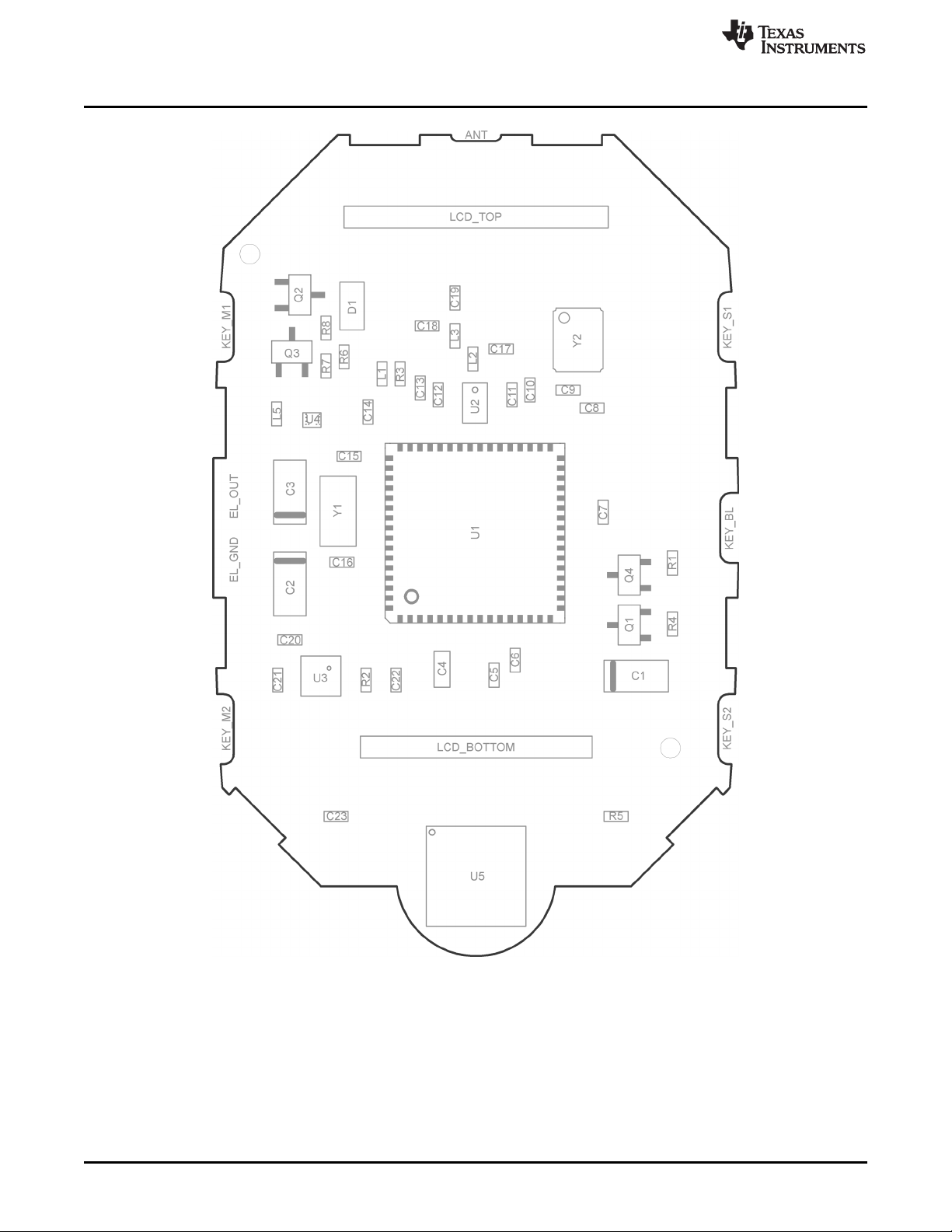
Schematics, Layout, BOM, and LCD
www.ti.com
Figure 4-22. eZ430-Chronos-433 Wrist Module With White PCB, PCB Components on Top Layer
74
eZ430-Chronos Hardware SLAU292F–November 2009–Revised October 2013
Copyright © 2009–2013, Texas Instruments Incorporated
Submit Documentation Feedback
Page 75
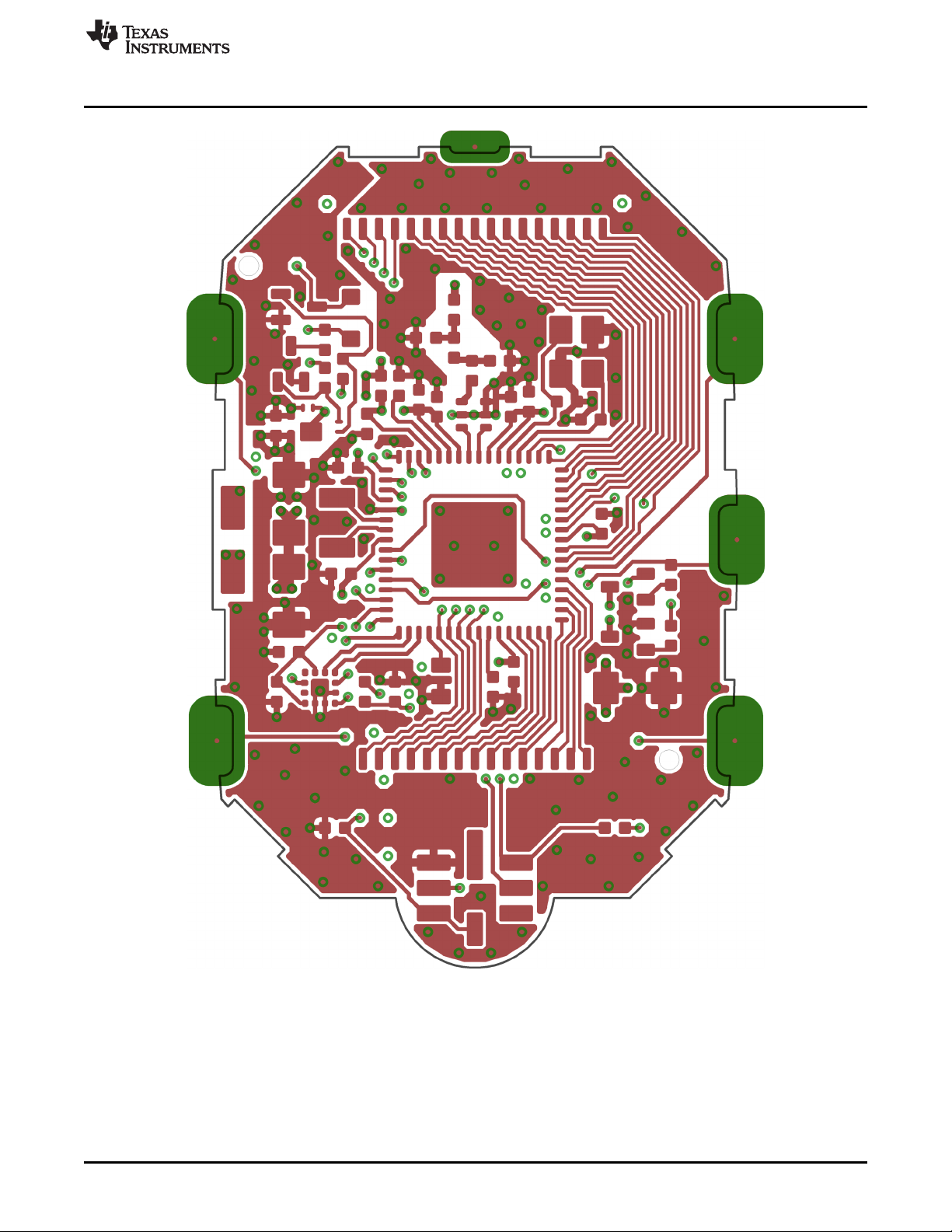
www.ti.com
Schematics, Layout, BOM, and LCD
Figure 4-23. eZ430-Chronos-433 Wrist Module With White PCB, Layout Top Layer (LCD Side)
SLAU292F–November 2009–Revised October 2013 eZ430-Chronos Hardware
Submit Documentation Feedback
Copyright © 2009–2013, Texas Instruments Incorporated
75
Page 76

Schematics, Layout, BOM, and LCD
www.ti.com
76
Figure 4-24. eZ430-Chronos-433 Wrist Module With White PCB, Layout Second Layer
eZ430-Chronos Hardware SLAU292F–November 2009–Revised October 2013
Copyright © 2009–2013, Texas Instruments Incorporated
Submit Documentation Feedback
Page 77
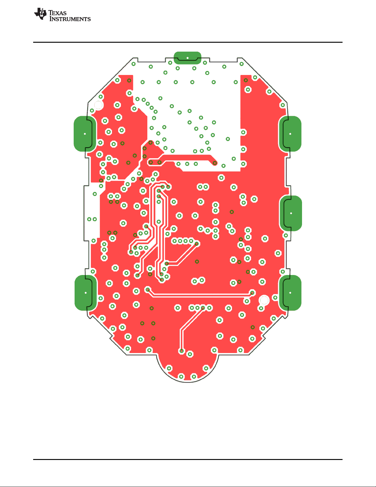
www.ti.com
Schematics, Layout, BOM, and LCD
Figure 4-25. eZ430-Chronos-433 Wrist Module With White PCB, Layout Third Layer
SLAU292F–November 2009–Revised October 2013 eZ430-Chronos Hardware
Submit Documentation Feedback
Copyright © 2009–2013, Texas Instruments Incorporated
77
Page 78
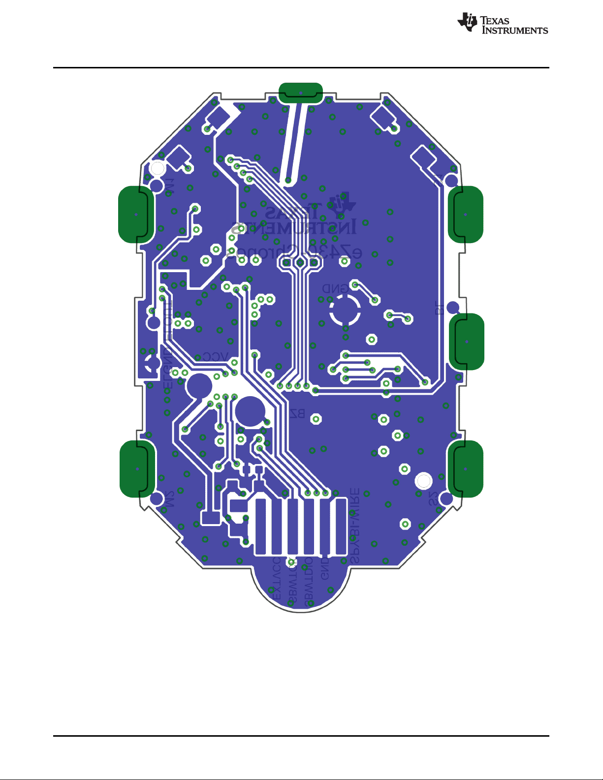
Schematics, Layout, BOM, and LCD
www.ti.com
Figure 4-26. eZ430-Chronos-433 Wrist Module With White PCB, Layout Bottom Layer (Battery Side)
78
eZ430-Chronos Hardware SLAU292F–November 2009–Revised October 2013
Copyright © 2009–2013, Texas Instruments Incorporated
Submit Documentation Feedback
Page 79

www.ti.com
Schematics, Layout, BOM, and LCD
Table 4-3. eZ430-Chronos-433 Wrist Module With White PCB, BOM List
Designator Value Tolerance Footprint Description Manufacturer
C1 47 µF ±20% TAJ-A Capacitor SMD Tantalum, height max. 1.6 mm
C2 47 µF ±20% TAJ-A Capacitor SMD Tantalum, height max. 1.6 mm
C3 47 µF ±20% TAJ-A Capacitor SMD Tantalum, height max. 1.6 mm
C4 4.7 µF ±20%, X5R 603 Capacitor SMD
C5 470 nF ±10%, X5R 402 Capacitor SMD
C6 100 nF ±10%, X5R or X7R 402 Capacitor SMD
C7 100 nF ±10%, X5R or X7R 402 Capacitor SMD
C8 15 pF ±5%, COG/NP0 402 Capacitor SMD
C9 15 pF ±5%, COG/NP0 402 Capacitor SMD
C10 10 nF ±10%, X7R 402 Capacitor SMD
C11 2.2 pF ±0.25 pF, COG/NP0 402 Capacitor SMD
C12 10 nF ±10%, X7R 402 Capacitor SMD
C13 220 pF ±10%, COG/NP0 402 Capacitor SMD
C14 100 nF ±10%, X5R or X7R 402 Capacitor SMD
C15 100 nF ±10%, X5R or X7R 402 Capacitor SMD
C16 100 nF ±10%, X5R or X7R 402 Capacitor SMD
C17 N.A.
C18 N.A.
C19 220 pF ±10%, COG/NP0 402 Capacitor SMD
C20 100 nF ±10%, X5R or X7R 402 Capacitor SMD
C21 100 nF ±10%, X5R or X7R 402 Capacitor SMD
C22 2.2 nF ±10%, X7R 402 Capacitor SMD
C23 100 nF ±10%, X5R or X7R 402 Capacitor SMD
D1 1SS355 SOD323 Diode SMD
D2 1SS355 SOD323 Diode SMD
L1 12 nH ±5% 402 Inductor Monolithic SMD Johanson L-07C12NJV4
L2(R) 0R ±5% 402 Resistor SMD
L3 18 nH ±5% 402 Inductor Monolithic SMD Johanson L-07C18NJV4
L4 RDC≤250Ω, ±10% Inductor Coil
L5 100 nH ±10% 402 Inductor Monolithic SMD
L6 ±10% Inductor Coil
P1 Connector SMD e.g. MPE-Garry BL SMD 91-06
PCB1
Q1 SOT323
Q2 SOT323
Q3 SOT323
Q4 SOT323
Q5 NTR4101P SOT23 P-Channel MOSFET SMD
R1 470R ±5% 402 Resistor SMD
R2 47k ±5% 402 Resistor SMD
R3 56k ±1% 402 Resistor SMD
R4 47k ±5% 402 Resistor SMD
R5 10k ±5% 402 Resistor SMD
R6 10k ±5% 402 Resistor SMD
R7 10k ±5% 402 Resistor SMD
R8 10k ±5% 402 Resistor SMD
35mH,
IDC≥1mA
4 mH, RDC≤100Ω,
IDC≥10mA
Female Header
1.27mm
CUSTOM, solder PCB, 4 layers, 0.6 mm
stop white thick
BC846BW or Bipolar Transistor NPN
BC847BW SMD
BC846BW or Bipolar Transistor NPN
BC847BW SMD
BC846BW or Bipolar Transistor NPN
BC847BW SMD
BC846BW or Bipolar Transistor NPN
BC847BW SMD
SLAU292F–November 2009–Revised October 2013 eZ430-Chronos Hardware
Submit Documentation Feedback
Copyright © 2009–2013, Texas Instruments Incorporated
79
Page 80

Schematics, Layout, BOM, and LCD
Table 4-3. eZ430-Chronos-433 Wrist Module With White PCB, BOM List (continued)
Designator Value Tolerance Footprint Description Manufacturer
R9 100k ±5% 402 Resistor SMD
U1 CC430F6137IRGC QFN64 TI
U2 0433BM15A0001 Balun 433MHz Johanson
U3 BMA250 LGA12 Acceleration Sensor SPI Bosch Sensortec
U4 HKA5403Q-30 DIE EL Driver
U5 BMP085 Pressure Sensor I2C Bosch Sensortec
Y1 CL=12.5pF, ±20ppm Crystal SMD Microcrystal CM7V-T1A
Y2 ±10ppm Crystal SMD Epson TSX3225-X1E000021014300
32.768kHz,
ESR≤80kΩ
26MHz, CL=10pF,
ESR≤40Ω
3.2 x
1.5mm
3.2 x 2.5
2
mm
www.ti.com
MCU with ISM
Transceiver
2
80
eZ430-Chronos Hardware SLAU292F–November 2009–Revised October 2013
Copyright © 2009–2013, Texas Instruments Incorporated
Submit Documentation Feedback
Page 81
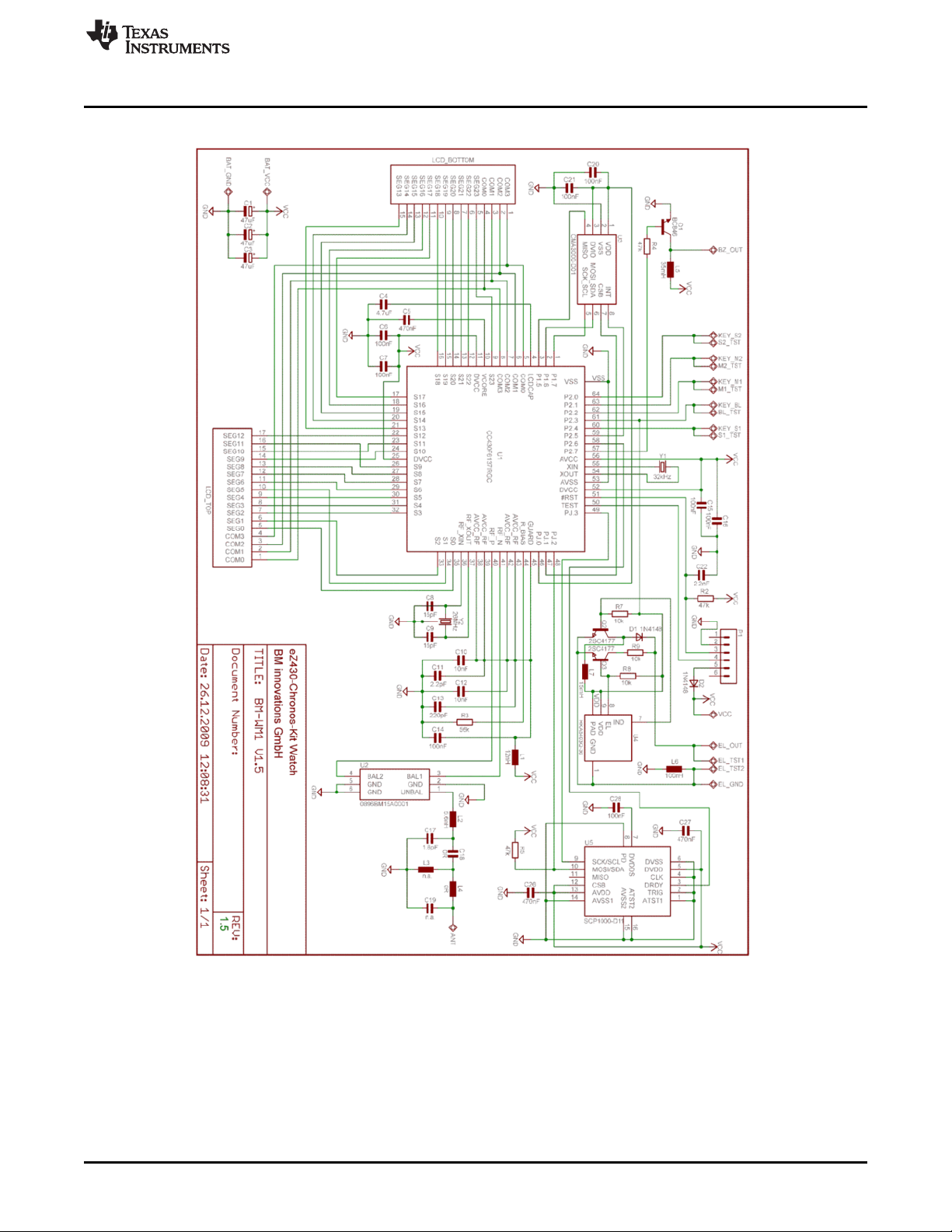
www.ti.com
4.5.3 eZ430-Chronos-868 and -915 Wrist Modules With Black PCB
Schematics, Layout, BOM, and LCD
Figure 4-27. eZ430-Chronos-868 and -915 Wrist Modules With Black PCBs, Schematics
SLAU292F–November 2009–Revised October 2013 eZ430-Chronos Hardware
Submit Documentation Feedback
Copyright © 2009–2013, Texas Instruments Incorporated
81
Page 82

Schematics, Layout, BOM, and LCD
www.ti.com
Figure 4-28. eZ430-Chronos-868 and -915 Wrist Modules With Black PCBs, PCB Components on Top
Layer
82
eZ430-Chronos Hardware SLAU292F–November 2009–Revised October 2013
Copyright © 2009–2013, Texas Instruments Incorporated
Submit Documentation Feedback
Page 83

www.ti.com
Schematics, Layout, BOM, and LCD
Figure 4-29. eZ430-Chronos-868 and -915 Wrist Modules With Black PCBs, Layout Top Layer (LCD Side)
SLAU292F–November 2009–Revised October 2013 eZ430-Chronos Hardware
Submit Documentation Feedback
Copyright © 2009–2013, Texas Instruments Incorporated
83
Page 84
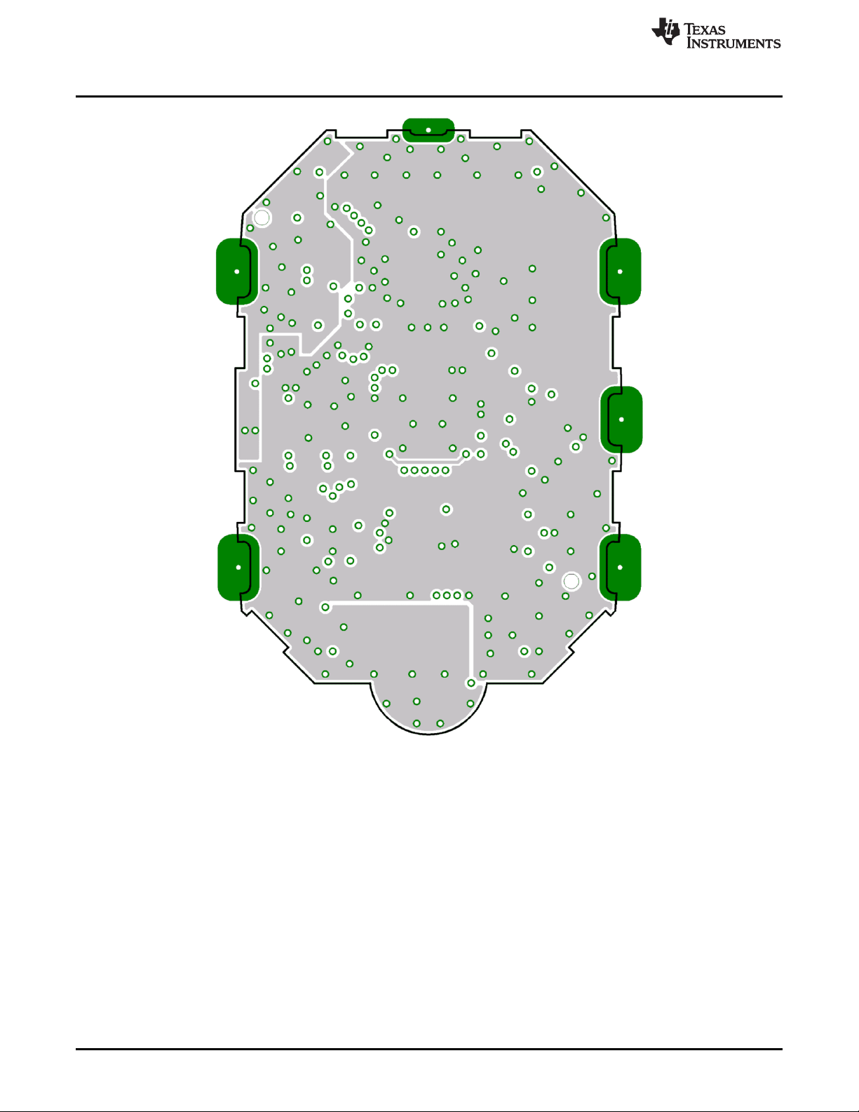
Schematics, Layout, BOM, and LCD
www.ti.com
Figure 4-30. eZ430-Chronos-868 and -915 Wrist Modules With Black PCBs, Layout Second Layer
84
eZ430-Chronos Hardware SLAU292F–November 2009–Revised October 2013
Copyright © 2009–2013, Texas Instruments Incorporated
Submit Documentation Feedback
Page 85
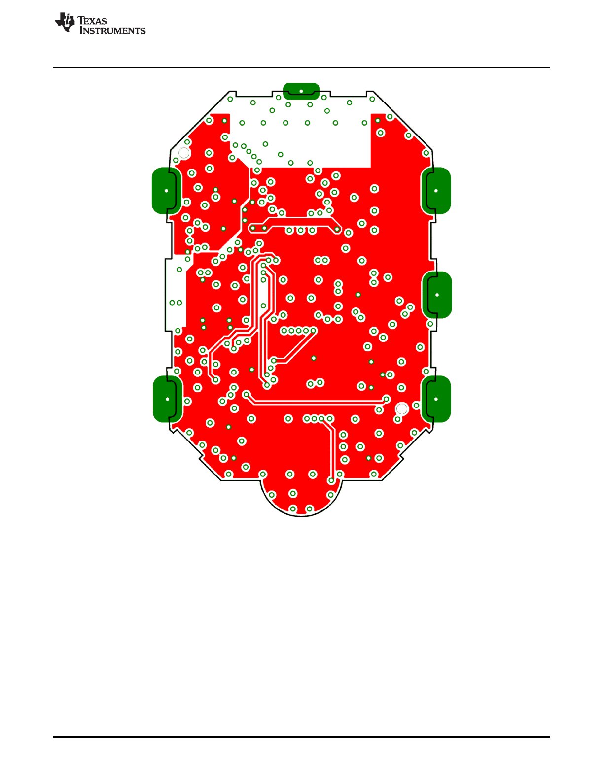
www.ti.com
Schematics, Layout, BOM, and LCD
Figure 4-31. eZ430-Chronos-868 and -915 Wrist Modules With Black PCBs, Layout Third Layer
SLAU292F–November 2009–Revised October 2013 eZ430-Chronos Hardware
Submit Documentation Feedback
Copyright © 2009–2013, Texas Instruments Incorporated
85
Page 86

Schematics, Layout, BOM, and LCD
www.ti.com
Figure 4-32. eZ430-Chronos-868 and -915 Wrist Modules With Black PCBs, Layout Bottom Layer (Battery
Side)
86
eZ430-Chronos Hardware SLAU292F–November 2009–Revised October 2013
Copyright © 2009–2013, Texas Instruments Incorporated
Submit Documentation Feedback
Page 87

www.ti.com
Schematics, Layout, BOM, and LCD
Table 4-4. eZ430-Chronos-868 and -915 Wrist Modules With Black PCBs, BOM List
Designator Value Tolerance Footprint Description Manufacturer
C1 47 µF ±20% TAJ-A Capacitor SMD Tantalum, height max. 1.6mm
C2 47 µF ±20% TAJ-A Capacitor SMD Tantalum, height max. 1.6mm
C3 47 µF ±20% TAJ-A Capacitor SMD Tantalum, height max. 1.6mm
C4 4.7 µF ±20%, X5R 603 Capacitor SMD
C5 470 nF ±10%, X5R 402 Capacitor SMD
C6 100 nF ±10%, X7R 402 Capacitor SMD
C7 100 nF ±10%, X7R 402 Capacitor SMD
C8 15 pF ±5%, COG/NP0 402 Capacitor SMD
C9 15 pF ±5%, COG/NP0 402 Capacitor SMD
C10 10 nF ±10%, X7R 402 Capacitor SMD
C11 2.2 pF ±0.25pF, COG/NP0 402 Capacitor SMD
C12 10 nF ±10%, X7R 402 Capacitor SMD
C13 220 pF ±10%, COG/NP0 402 Capacitor SMD
C14 100 nF ±10%, X7R 402 Capacitor SMD
C15 100 nF ±10%, X7R 402 Capacitor SMD
C16 100 nF ±10%, X7R 402 Capacitor SMD
C17 1.8 pF ±0.1pF, COG/NP0 402 Capacitor SMD Johanson 500R07S1R8BV4
C18 0R ±5% 402 Resistor SMD
C19 N.A.
C20 100 nF ±10%, X7R 402 Capacitor SMD
C21 100 nF ±10%, X7R 402 Capacitor SMD
C22 2.2 nF ±10%, X7R 402 Capacitor SMD
C26 470 nF ±10%, X5R 402 Capacitor SMD
C27 470 nF ±10%, X5R 402 Capacitor SMD
C28 100 nF ±10%, X7R 402 Capacitor SMD
D1 1N4148 805 Diode SMD
D2 1N4148 805 Diode SMD
L1 12 nH ±5% 402 Inductor Monolithic SMD Johanson L-07C12NJV4
L2 5.6 nH ±0.3nH 402 Inductor Monolithic SMD Johanson L-07C5N6SV4
L3 N.A.
L4 0R ±5% 402 Resistor SMD
L5 RDC≤250Ω, ±10% Inductor Coil
L6 100nH ±10% 402 Inductor Monolithic SMD
L7 ±10% Inductor Coil
P1 Connector SMD for example, MPE-Garry BL SMD 91-06
PCB1
Q1 SOT323
Q2 SOT323
Q3 SOT323
R2 47k ±5% 402 Resistor SMD
R3 56k ±1% 402 Resistor SMD
R4 47k ±5% 402 Resistor SMD
R5 47k ±5% 402 Resistor SMD
R7 10k ±5% 402 Resistor SMD
R8 10k ±5% 402 Resistor SMD
R9 10k ±5% 402 Resistor SMD
35 mH,
IDC≥1mA
4mH, RDC≤100Ω,
IDC≥10mA
Female Header
1.27mm
CUSTOM, solder PCB, 4 layers, 0.6 mm
stop black thick
BC846BW or Bipolar Transistor NPN
BC847BW SMD
BC846BW or Bipolar Transistor NPN
BC847BW SMD
BC846BW or Bipolar Transistor NPN
BC847BW SMD
SLAU292F–November 2009–Revised October 2013 eZ430-Chronos Hardware
Submit Documentation Feedback
Copyright © 2009–2013, Texas Instruments Incorporated
87
Page 88

Schematics, Layout, BOM, and LCD
Table 4-4. eZ430-Chronos-868 and -915 Wrist Modules With Black PCBs, BOM List (continued)
Designator Value Tolerance Footprint Description Manufacturer
U1 CC430F6137IRGC QFN64 TI
U2 0896BM15A0001 896MHz Balun Johanson
U3 CMA3000-D01 WLP Acceleration Sensor SPI VTI
U4 HKA5403Q-30 DIE EL Driver
U5 SCP1000-D11 Pressure Sensor I2C VTI
Y1 CL=12.5pF, ±20ppm Crystal SMD Microcrystal CC7V-T1A
Y2 ±10ppm Crystal SMD Epson TSX3225-X1E000021014300
32.768kHz,
ESR≤80kΩ
26MHz, CL=10pF,
ESR≤40Ω
3.2 x 1.5
2
mm
3.2 x 2.5
2
mm
www.ti.com
MCU with ISM
Transceiver
88
eZ430-Chronos Hardware SLAU292F–November 2009–Revised October 2013
Copyright © 2009–2013, Texas Instruments Incorporated
Submit Documentation Feedback
Page 89
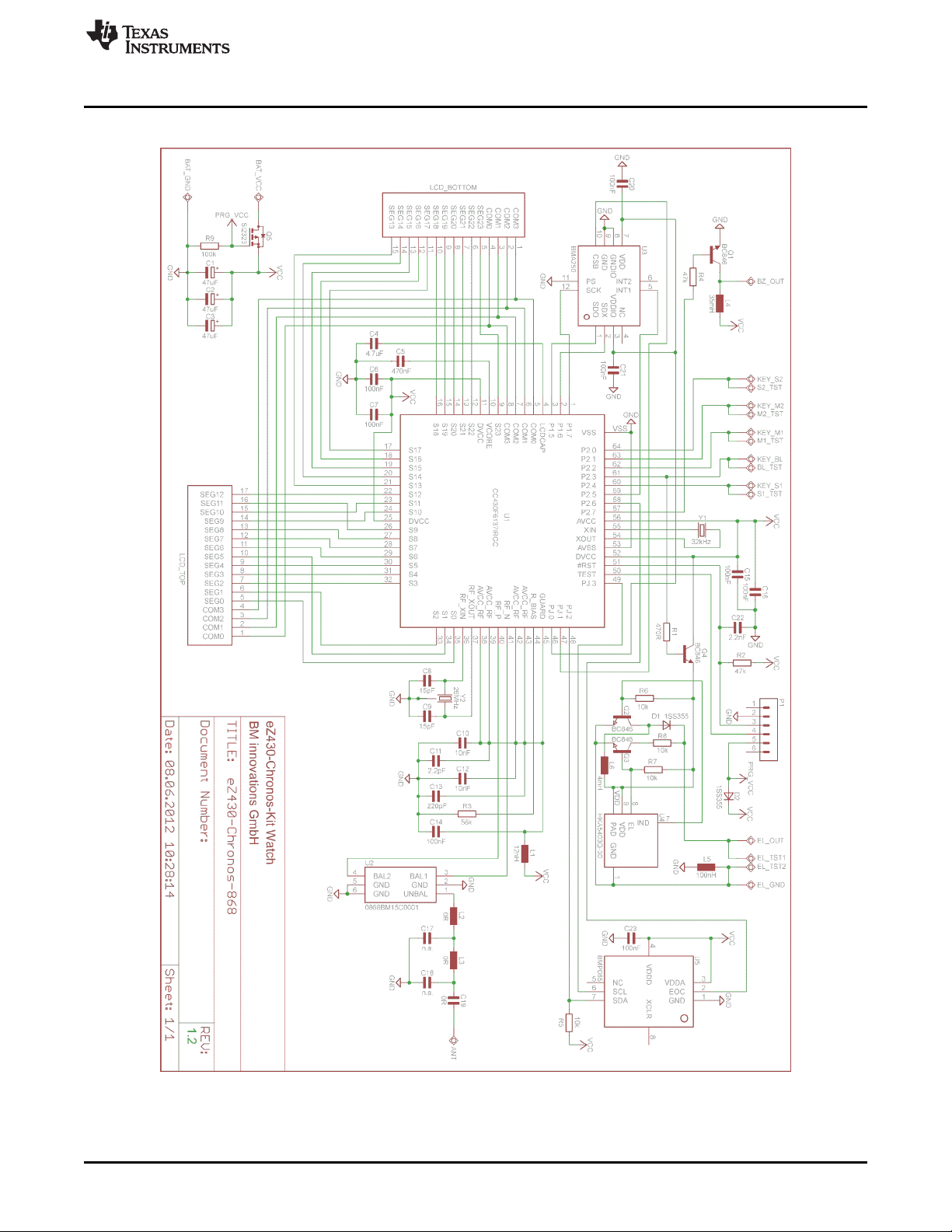
www.ti.com
4.5.4 eZ430-Chronos-868 and -915 Wrist Modules With White PCB
Schematics, Layout, BOM, and LCD
Figure 4-33. eZ430-Chronos-868 Wrist Modules With White PCBs, Schematics
SLAU292F–November 2009–Revised October 2013 eZ430-Chronos Hardware
Submit Documentation Feedback
Copyright © 2009–2013, Texas Instruments Incorporated
89
Page 90
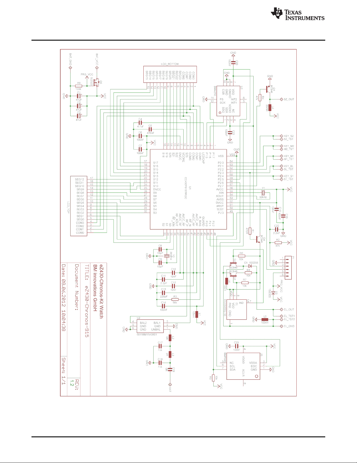
Schematics, Layout, BOM, and LCD
www.ti.com
90
Figure 4-34. eZ430-Chronos-915 Wrist Modules With White PCBs, Schematics
eZ430-Chronos Hardware SLAU292F–November 2009–Revised October 2013
Copyright © 2009–2013, Texas Instruments Incorporated
Submit Documentation Feedback
Page 91
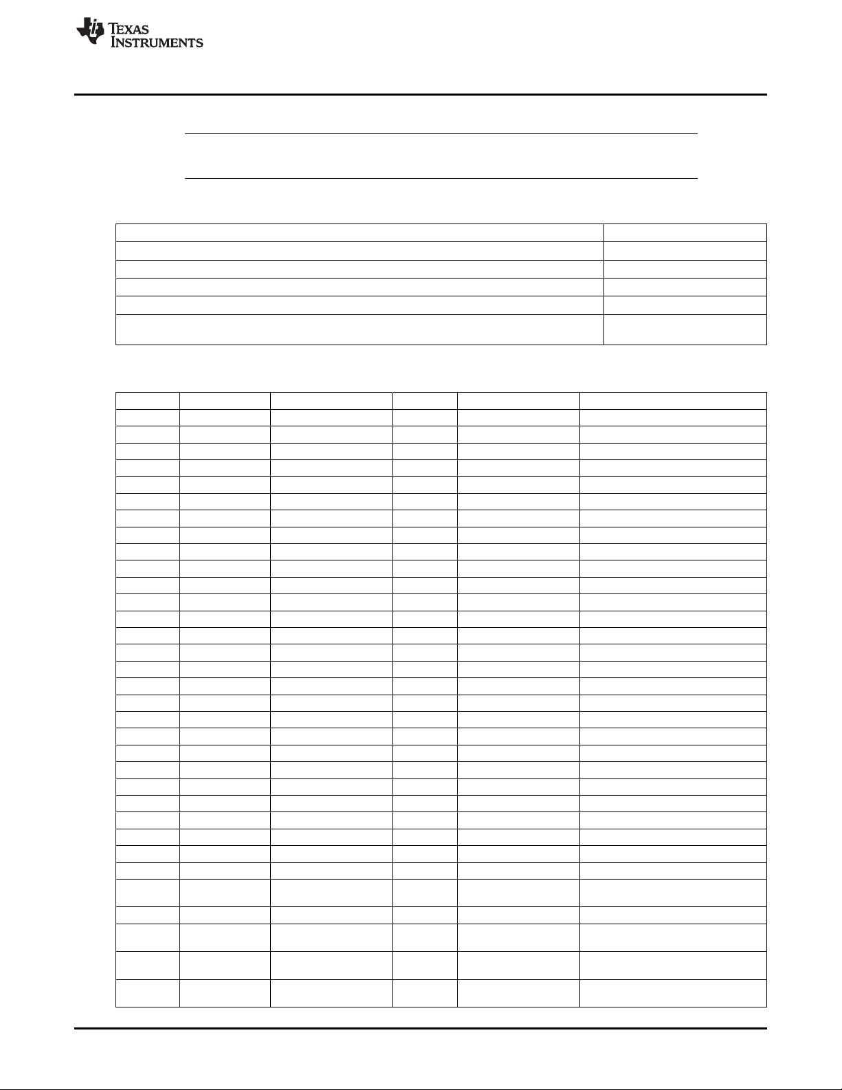
www.ti.com
Schematics, Layout, BOM, and LCD
NOTE: The layers for the eZ430-Chronos-433 wrist module with White PCB also apply to the
following layers. Table 4-5 shows the applicable images.
Table 4-5. eZ430-Chronos-868 and -915 PCB Cross Reference
PCB Layer Figure Reference
eZ430-Chronos-868 and -915 Wrist Modules With White PCBs, PCB Components on Top Layer Figure 4-22
eZ430-Chronos-868 and -915 Wrist Modules With White PCBs, Layout Top Layer (LCD Side) Figure 4-23
eZ430-Chronos-868 and -915 Wrist Modules With White PCBs, Layout Second Layer Figure 4-24
eZ430-Chronos-868 and -915 Wrist Modules With White PCBs, Layout Third Layer Figure 4-25
eZ430-Chronos-868 and -915 Wrist Modules With White PCBs, Layout Bottom Layer (Battery
Side)
Figure 4-26
Table 4-6. eZ430-Chronos-868 Wrist Module With White PCB, BOM List
Designator Value Tolerance Footprint Description Manufacturer
C1 47 µF ±20% TAJ-A Capacitor SMD Tantalum, height max. 1.6 mm
C2 47 µF ±20% TAJ-A Capacitor SMD Tantalum, height max. 1.6 mm
C3 47 µF ±20% TAJ-A Capacitor SMD Tantalum, height max. 1.6 mm
C4 4.7 µF ±20%, X5R 603 Capacitor SMD
C5 470 nF ±10%, X5R 402 Capacitor SMD
C6 100 nF ±10%, X5R or X7R 402 Capacitor SMD
C7 100 nF ±10%, X5R or X7R 402 Capacitor SMD
C8 15 pF ±5%, COG/NP0 402 Capacitor SMD
C9 15 pF ±5%, COG/NP0 402 Capacitor SMD
C10 10 nF ±10%, X7R 402 Capacitor SMD
C11 2.2 pF ±0.25pF, COG/NP0 402 Capacitor SMD
C12 10 nF ±10%, X7R 402 Capacitor SMD
C13 220 pF ±10%, COG/NP0 402 Capacitor SMD
C14 100 nF ±10%, X5R or X7R 402 Capacitor SMD
C15 100 nF ±10%, X5R or X7R 402 Capacitor SMD
C16 100 nF ±10%, X5R or X7R 402 Capacitor SMD
C17 N.A.
C18 N.A.
C19 (R) 0R ±5% 402 Capacitor SMD
C20 100 nF ±10%, X5R or X7R 402 Capacitor SMD
C21 100 nF ±10%, X5R or X7R 402 Capacitor SMD
C22 2.2 nF ±10%, X7R 402 Capacitor SMD
C23 100 nF ±10%, X5R or X7R 402 Capacitor SMD
D1 1SS355 SOD323 Diode SMD
D2 1SS355 SOD323 Diode SMD
L1 12 nH ±5% 402 Inductor Monolithic SMD Johanson L-07C12NJV4
L2 (R) 0R ±5% 402 Resistor SMD
L3 (R) 0R ±5% 402 Resistor SMD
L4 ±10% Inductor Coil
L5 100 nH ±10% 402 Inductor Monolithic SMD
L6 ±10% Inductor Coil
P1 Connector SMD e.g. MPE-Garry BL SMD 91-06
PCB1
35 mH, RDC≤250
Ω, IDC≥1 mA
4 mH, RDC≤100
Ω, IDC≥10 mA
Female Header
1.27mm
CUSTOM, solder PCB, 4 layers, 0.6 mm
stop white thick
SLAU292F–November 2009–Revised October 2013 eZ430-Chronos Hardware
Submit Documentation Feedback
Copyright © 2009–2013, Texas Instruments Incorporated
91
Page 92

Schematics, Layout, BOM, and LCD
Table 4-6. eZ430-Chronos-868 Wrist Module With White PCB, BOM List (continued)
Designator Value Tolerance Footprint Description Manufacturer
Q1 SOT323
Q2 SOT323
Q3 SOT323
Q4 SOT323
Q5 NTR4101P SOT23 P-Channel MOSFET SMD
R1 470R ±5% 402 Resistor SMD
R2 47k ±5% 402 Resistor SMD
R3 56k ±1% 402 Resistor SMD
R4 47k ±5% 402 Resistor SMD
R5 10k ±5% 402 Resistor SMD
R6 10k ±5% 402 Resistor SMD
R7 10k ±5% 402 Resistor SMD
R8 10k ±5% 402 Resistor SMD
R9 100k ±5% 402 Resistor SMD
U1 CC430F6137IRGC QFN64 TI
U2 0868BM15C0001 Balun 868MHz Johanson
U3 BMA250 LGA12 Acceleration Sensor SPI Bosch Sensortec
U4 HKA5403Q-30 DIE EL Driver
U5 BMP085 Pressure Sensor I2C Bosch Sensortec
Y1 CL=12.5pF, ±20ppm Crystal SMD Microcrystal CM7V-T1A
Y2 ±10ppm Crystal SMD Epson TSX3225-X1E000021014300
BC846BW or Bipolar Transistor NPN
BC847BW SMD
BC846BW or Bipolar Transistor NPN
BC847BW SMD
BC846BW or Bipolar Transistor NPN
BC847BW SMD
BC846BW or Bipolar Transistor NPN
BC847BW SMD
32.768kHz,
ESR≤80kΩ
26MHz, CL=10pF,
ESR≤40Ω
3.2 x 1.5
2
mm
3.2 x 2.5
2
mm
www.ti.com
MCU with ISM
Transceiver
NOTE: The BOM in Table 4-6 also applies to the eZ430-Chronos-915 wrist module with White PCB
except as shown in the following table.
Designator Value Tolerance Footprint Description Manufacturer
U2 0915BM15A0001 Balun 915MHz Johanson
92
eZ430-Chronos Hardware SLAU292F–November 2009–Revised October 2013
Copyright © 2009–2013, Texas Instruments Incorporated
Submit Documentation Feedback
Page 93
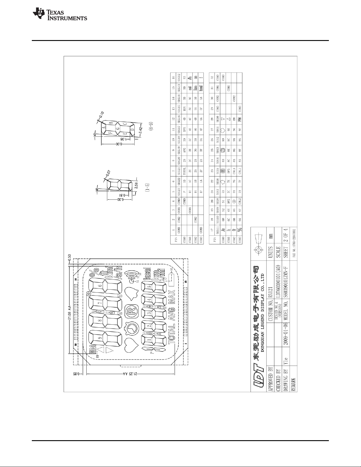
www.ti.com
4.5.5 LCD
Schematics, Layout, BOM, and LCD
Figure 4-35. LCD Segment Map
SLAU292F–November 2009–Revised October 2013 eZ430-Chronos Hardware
Submit Documentation Feedback
Copyright © 2009–2013, Texas Instruments Incorporated
93
Page 94
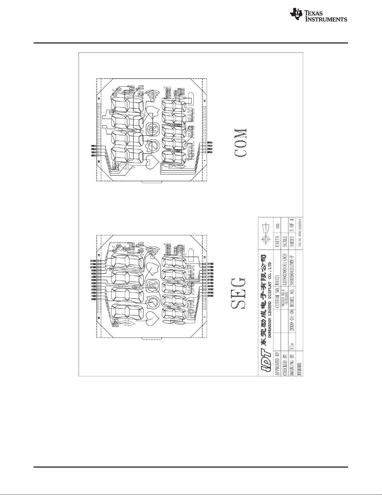
Schematics, Layout, BOM, and LCD
www.ti.com
94
Figure 4-36. LCD Pinout
eZ430-Chronos Hardware SLAU292F–November 2009–Revised October 2013
Copyright © 2009–2013, Texas Instruments Incorporated
Submit Documentation Feedback
Page 95
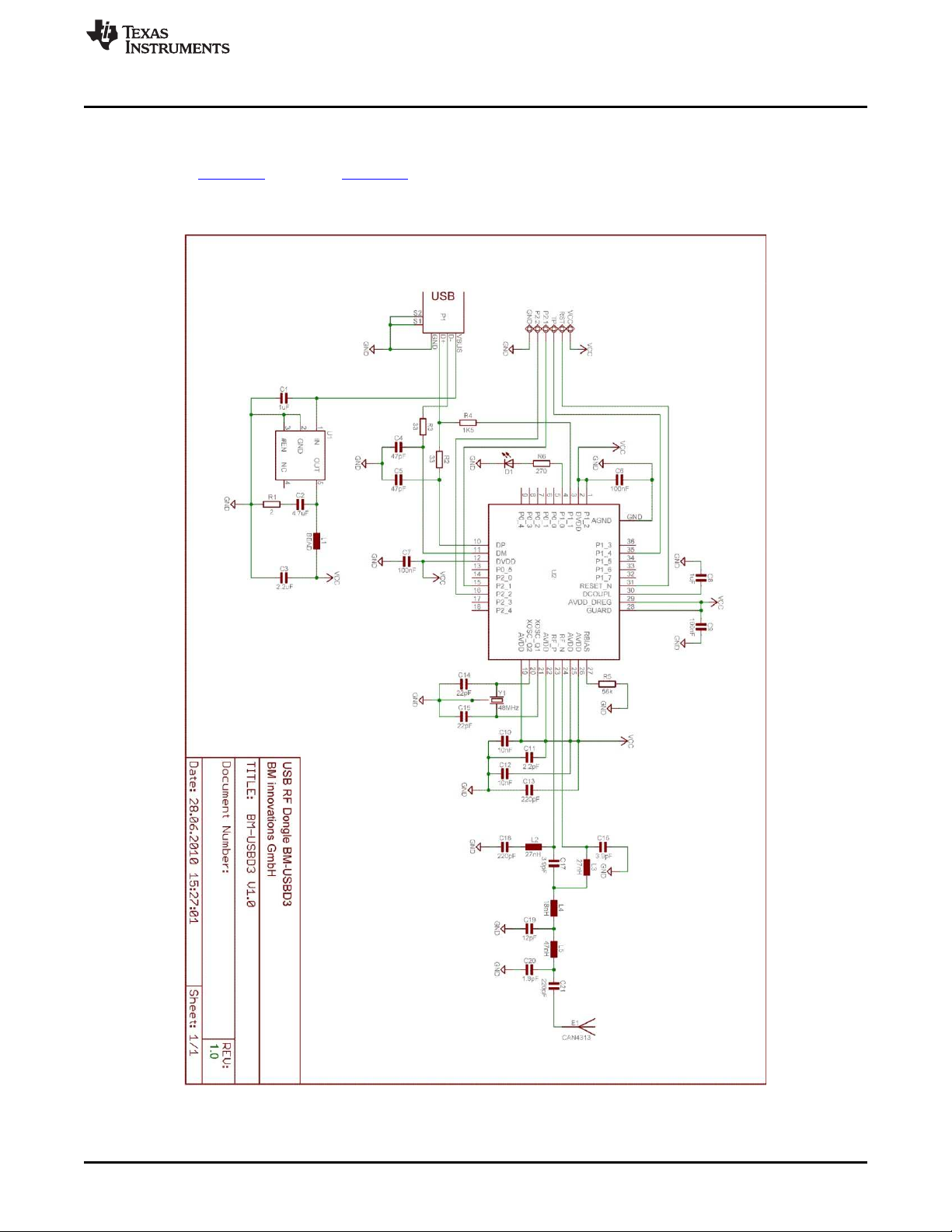
www.ti.com
4.6 Access Point Schematics, Layout, and BOM
Gerber files for the eZ430-Chronos access point are part of the eZ430-Chronos software packages for
Windows SLAC341 and Linux SLAC388.
4.6.1 eZ430-Chronos-433 With Black PCB RF Access Point
Access Point Schematics, Layout, and BOM
Figure 4-37. eZ430-Chronos-433 RF Access Point With Black PCB, Schematics
SLAU292F–November 2009–Revised October 2013 eZ430-Chronos Hardware
Submit Documentation Feedback
Copyright © 2009–2013, Texas Instruments Incorporated
95
Page 96
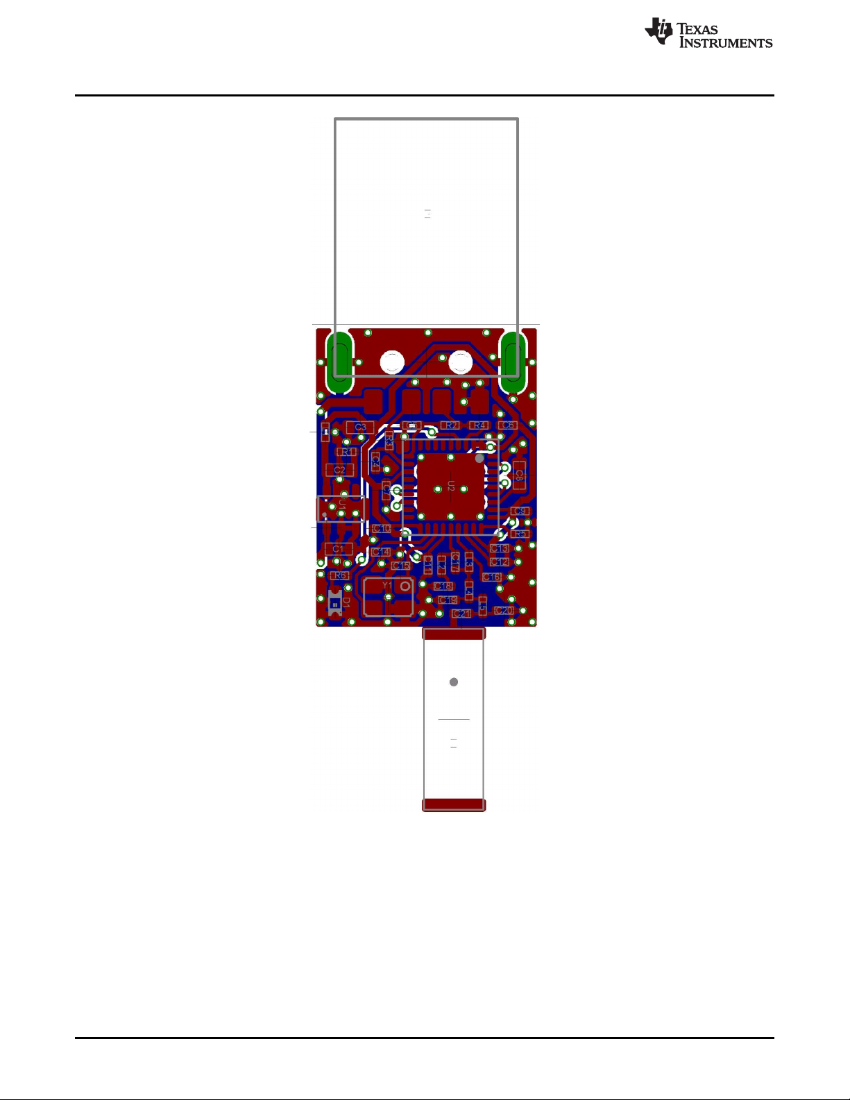
Access Point Schematics, Layout, and BOM
www.ti.com
Figure 4-38. eZ430-Chronos-433 RF Access Point With Black PCB, PCB Components on Top Layer
96
eZ430-Chronos Hardware SLAU292F–November 2009–Revised October 2013
Copyright © 2009–2013, Texas Instruments Incorporated
Submit Documentation Feedback
Page 97
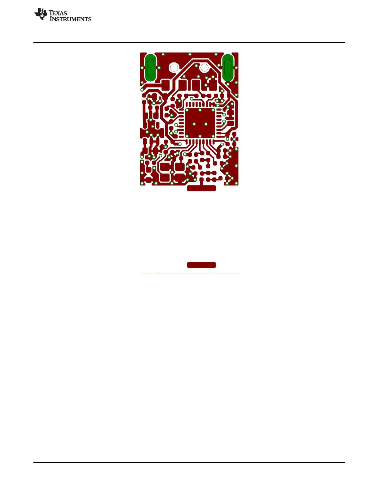
www.ti.com
Access Point Schematics, Layout, and BOM
Figure 4-39. eZ430-Chronos-433 RF Access Point With Black PCB, Layout Top Layer
SLAU292F–November 2009–Revised October 2013 eZ430-Chronos Hardware
Submit Documentation Feedback
Copyright © 2009–2013, Texas Instruments Incorporated
97
Page 98

Access Point Schematics, Layout, and BOM
www.ti.com
Figure 4-40. eZ430-Chronos-433 RF Access Point With Black PCB, Layout Bottom Layer
98
eZ430-Chronos Hardware SLAU292F–November 2009–Revised October 2013
Copyright © 2009–2013, Texas Instruments Incorporated
Submit Documentation Feedback
Page 99

www.ti.com
Access Point Schematics, Layout, and BOM
Table 4-7. eZ430-Chronos-433 Access Point With Black PCB, BOM List
Designator Value Tolerance Footprint Description Manufacturer
C1 1 µF ±10%,X5R 603 Capacitor SMD
C2 4.7 µF ±10%, X5R 603 Capacitor SMD
C3 2.2 µF ±10%, X5R 603 Capacitor SMD
C4 47 pF ±10%, COG/NP0 402 Capacitor SMD
C5 47 pF ±10%, COG/NP0 402 Capacitor SMD
C6 100 nF ±10%, X7R 402 Capacitor SMD
C7 100 nF ±10%, X7R 402 Capacitor SMD
C8 1 µF ±10%,X5R 603 Capacitor SMD
C9 100 nF ±10%, X7R 402 Capacitor SMD
C10 10 nF ±10%, X7R 402 Capacitor SMD
C11 2.2 pF ±0.25pF, COG/NP0 402 Capacitor SMD
C12 10 nF ±10%, X7R 402 Capacitor SMD
C13 220 pF ±10%, COG/NP0 402 Capacitor SMD
C14 22 pF ±5%, COG/NP0 402 Capacitor SMD
C15 22 pF ±5%, COG/NP0 402 Capacitor SMD
C16 3.9 pF ±0.1pF, COG/NP0 402 Capacitor SMD Johanson 500R07S3R9BV4
C17 3.9 pF ±0.1pF, COG/NP0 402 Capacitor SMD Johanson 500R07S3R9BV4
C18 220 pF ±10%, COG/NP0 402 Capacitor SMD
C18 220 pF ±10%, COG/NP0 402 Capacitor SMD
C19 220 pF ±10%, COG/NP0 402 Capacitor SMD
C20 220 pF ±10%, COG/NP0 402 Capacitor SMD
C21 220 pF ±10%, COG/NP0 402 Capacitor SMD
D1 green 603 LED SMD
E1 0868AT43A0020 Chip Antenna Johanson
L1 402 EMI Filter SMD for example, TDK MMZ1005S102C
L2 27 nH ±5% 402 Inductor Monolithic SMD Johanson L-07C27NJV4
L3 27 nH ±5% 402 Inductor Monolithic SMD Johanson L-07C27NJV4
L4 18 nH ±5% 402 Inductor Monolithic SMD Johanson L-07C18NJV4
L5 47nH ±5% 402 Inductor Monolithic SMD Johanson L-07C47NJV4
P1 USB Type A USB Plug for example, Lumberg 241007
PCB1
R1 2R ±5% 402 Resistor SMD
R2 33R ±5% 402 Resistor SMD
R3 33R ±5% 402 Resistor SMD
R4 1.5k ±5% 402 Resistor SMD
R5 56k ±1% 402 Resistor SMD
R6 270R ±5% 402 Resistor SMD
U1 TPS76933DBV SOT-23 Linear Regulator TI
U2 CC1111F32RSP QFN36 ISM Transceiver TI
Y1 ±10ppm Crystal SMD Epson TSX3225-X1E000021040300
Ferrite Bead 1k,
1R, min. 100mA
CUSTOM, solder PCB, 2 layers, 0.8 mm
stop black thick
48MHz, CL=16pF,
ESR≤40Ω
23.2 x 2.5
2
mm
SLAU292F–November 2009–Revised October 2013 eZ430-Chronos Hardware
Submit Documentation Feedback
Copyright © 2009–2013, Texas Instruments Incorporated
99
Page 100
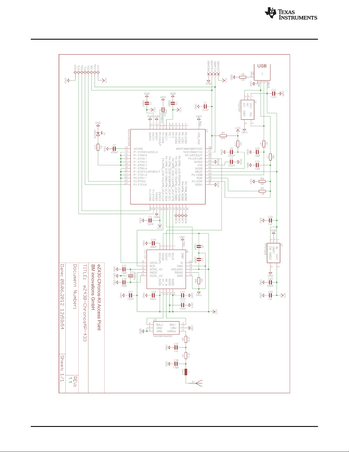
Access Point Schematics, Layout, and BOM
4.6.2 eZ430-Chronos-433 With White PCB RF Access Point
www.ti.com
100
Figure 4-41. eZ430-Chronos-433 RF Access Point With White PCB, Schematics
eZ430-Chronos Hardware SLAU292F–November 2009–Revised October 2013
Copyright © 2009–2013, Texas Instruments Incorporated
Submit Documentation Feedback
 Loading...