


GB I F D E P
NL DK SF N S GR RU H RO PL CZ SK SI HR/SCG LT EE LV BG
INSTRUCTION MANUAL |
Cod.953552 |
|
|
MANUALE D’ISTRUZIONE |
|
MANUEL D’INSTRUCTIONS |
|
BEDIENUNGSANLEITUNG |
|
MANUAL DE INSTRUCCIONES |
|
MANUAL DE INSTRUÇÕES |
|
INSTRUCTIEHANDLEIDING |
|
INSTRUKTIONSMANUAL |
|
OHJEKIRJA |
|
BRUKERVEILEDNING |
|
BRUKSANVISNING |
|
ΕΓΧΕΙΡΙΔΙΟ ΧΡΗΣΗΣ |
|
РУКОВОДСТВО ПОЛЬЗОВАТЕЛЯ |
|
HASZNÁLATI UTASÍTÁS |
|
MANUAL DE INSTRUCŢIUNI |
|
INSTRUKCJA OBSŁUGI |
|
NÁVOD K POUŽITÍ |
|
NÁVOD NA POUŽITIE |
|
PRIROČNIK Z NAVODILI ZA UPORABO |
|
PRIRUČNIK ZA UPOTREBU |
|
INSTRUKCIJŲ KNYGELĖ |
|
KASUTUSJUHEND |
|
ROKASGRĀMATA |
|
РЪКОВОДСТВО С ИНСТРУКЦИИ |
|
MIG-MAG • TIG • MMA
MIG-MAG SYNERGIC SYSTEMS MULTI PROCESS SYSTEMS
 Professional wire welding machines
 Saldatrici a filo professionali
 Postes de soudure à fil professionnels
 Professionelle Draht-Schweißmaschinen
 Soldadoras de hilo profesionales
 Aparelho de soldar de fio profissional
 Professionele draadlasmachines
 Professionelle trådsvejsemaskiner
 Ammattikäyttöön tarkoitetut lankahitsauslaitteet
 Sveisebrenner med trå for profesionelt bruk
 Professionella varmtrådssvetsar
 Επαγγελματικές συγκολλητικές μηχανές σύρματος
 Профессиональные сварочные аппараты с использованием проволоки
 Professzionális huzalhegesztők
 Aparate de sudură cu sârmă destinate uzului profesional
 Profesjonalne spawarki do spawania drutem
 Profesionální svařovací přístroje pro svařování drátem
 Profesionálne zváracie prístroje
  Profesionalni varilni aparati z žico
 Profesionalni strojevi za varenje na žicu
 Profesionalūs aparatai suvirinimui viela
 Professionaalsed traatkeevitusaparaadid
 Profesionālie metināšanas aparāti ar stiepli
 Професионални електрожени за заваряване с електродна тел
- 1 -

GB |
|
|
EXPLANATION OF DANGER, MANDATORY AND PROHIBITION SIGNS. |
H |
A VESZÉLY, KÖTELEZETTSÉG ÉS TILTÁS JELZÉSEINEK FELIRATAI. |
|
I |
|
|
LEGENDA SEGNALI DI PERICOLO, D’OBBLIGO E DIVIETO. |
RO |
LEGENDĂ INDICATOARE DE AVERTIZARE A PERICOLELOR, DE OBLIGARE ŞI |
|
F |
|
|
LÉGENDE SIGNAUX DE DANGER, D’OBLIGATION ET D’INTERDICTION. |
PL |
DE INTERZICERE. |
|
D |
|
|
LEGENDE DER GEFAHREN-, GEBOTSUND VERBOTSZEICHEN. |
OBJAŚNIENIA ZNAKÓW OSTRZEGAWCZYCH, NAKAZU I ZAKAZU. |
||
E |
|
|
LEYENDA SEÑALES DE PELIGRO, DE OBLIGACIÓN Y PROHIBICIÓN. |
CZ |
VYSVĚTLIVKY K SIGNÁLŮM NEBEZPEČÍ, PŘÍKAZŮM A ZÁKAZŮM. |
|
P |
|
|
LEGENDA DOS SINAIS DE PERIGO, OBRIGAÇÃO E PROIBIDO. |
SK |
VYSVETLIVKY K SIGNÁLOM NEBEZPEČENSTVA, PRÍKAZOM A ZÁKAZOM. |
|
NL |
|
|
LEGENDE SIGNALEN VAN GEVAAR, VERPLICHTING EN VERBOD. |
SI |
LEGENDA SIGNALOV ZA NEVARNOST, ZA PREDPISANO IN PREPOVEDANO. |
|
DK |
|
|
OVERSIGT OVER FARE, PLIGT OG FORBUDSSIGNALER. |
HR/SCG |
LEGENDA OZNAKA OPASNOSTI, OBAVEZA I ZABRANA. |
|
SF |
|
|
VAROITUS, VELVOITUS, JA KIELTOMERKIT. |
LT |
PAVOJAUS, PRIVALOMŲJŲ IR DRAUDŽIAMŲJŲ ŽENKLŲ PAAIŠKINIMAS. |
|
N |
|
|
SIGNALERINGSTEKST FOR FARE, FORPLIKTELSER OG FORBUDT. |
EE |
OHUD, KOHUSTUSED JA KEELUD. |
|
S |
|
|
BILDTEXT SYMBOLER FÖR FARA, PÅBUD OCH FÖRBUD. |
LV |
BĪSTAMĪBU, PIENĀKUMU UN AIZLIEGUMA ZĪMJU PASKAIDROJUMI. |
|
GR |
|
|
ΛΕΖΑΝΤΑ ΣΗΜΑΤΩΝ ΚΙΝΔΥΝΟΥ, ΥΠΟΧΡΕΩΣΗΣ ΚΑΙ ΑΠΑΓΟΡΕΥΣΗΣ. |
BG |
ЛЕГЕНДА НА ЗНАЦИТЕ ЗА ОПАСНОСТ, ЗАДЪЛЖИТЕЛНИ И ЗА ЗАБРАНА. |
|
RU |
|
|
ЛЕГЕНДА СИМВОЛОВ БЕЗОПАСНОСТИ, ОБЯЗАННОСТИ И ЗАПРЕТА. |
|
|
|
|
|
|
|
|
||
|
|
|
|
DANGER OF ELECTRIC SHOCK - PERICOLO SHOCK ELETTRICO - RISQUE DE CHOC ÉLECTRIQUE - STROMSCHLAGGEFAHR - PELIGRO DESCARGA ELÉCTRICA - PERIGO |
||
|
|
|
|
DE CHOQUE ELÉTRICO - GEVAAR ELEKTROSHOCK - FARE FOR ELEKTRISK STØD - SÄHKÖISKUN VAARA - FARE FOR ELEKTRISK STØT - FARA FÖR ELEKTRISK STÖT - |
||
|
|
|
|
ΚΙΝΔΥΝΟΣ ΗΛΕΚΤΡΟΠΛΗΞΙΑΣ - ОПАСНОСТЬ ПОРАЖЕНИЯ ЭЛЕКТРИЧЕСКИМ ТОКОМ - ÁRAMÜTÉS VESZÉLYE - PERICOL DE ELECTROCUTARE - NIEBEZPIECZEŃSTWO |
||
|
|
|
|
SZOKU ELEKTRYCZNEGO - NEBEZPEČÍ ZÁSAHU ELEKTRICKÝM PROUDEM - NEBEZPEČENSTVO ZÁSAHU ELEKTRICKÝM PRÚDOM - NEVARNOST ELEKTRIČNEGA UDARA |
||
|
|
|
|
- OPASNOST STRUJNOG UDARA - ELEKTROS SMŪGIO PAVOJUS - ELEKTRILÖÖGIOHT - ELEKTROŠOKA BĪSTAMĪBA - ОПАСНОСТ ОТ ТОКОВ УДАР. |
||
|
|
|
|
|
||
|
|
|
|
DANGER OF WELDING FUMES - PERICOLO FUMI DI SALDATURA - DANGER FUMÉES DE SOUDAGE - GEFAHR DER ENTWICKLUNG VON RAUCHGASEN BEIM SCHWEISSEN |
||
|
|
|
|
- PELIGRO HUMOS DE SOLDADURA - PERIGO DE FUMAÇAS DE SOLDAGEM - GEVAAR LASROOK - FARE P.G.A. SVEJSEDAMPE - HITSAUSSAVUJEN VAARA - FARE FOR |
||
|
|
|
|
SVEISERØYK - FARA FÖR RÖK FRÅN SVETSNING - ΚΙΝΔΥΝΟΣ ΚΑΠΝΩΝ ΣΥΓΚΟΛΛΗΣΗΣ - ОПАСНОСТЬ ДЫМОВ СВАРКИ - HEGESZTÉS KÖVETKEZTÉBEN KELETKEZETT |
||
|
|
|
|
FÜST VESZÉLYE - PERICOL DE GAZE DE SUDURĂ - NIEBEZPIECZEŃSTWO OPARÓW SPAWALNICZYCH - NEBEZPEČÍ SVAŘOVACÍCH DÝMŮ - NEBEZPEČENSTVO VÝPAROV |
||
|
|
|
|
ZO ZVÁRANIA - NEVARNOST VARILNEGA DIMA - OPASNOST OD DIMA PRILIKOM VARENJA - SUVIRINIMO DŪMŲ PAVOJUS - KEEVITAMISEL SUITSU OHT - METINĀŠANAS |
||
|
|
|
|
IZTVAIKOJUMU BĪSTAMĪBA - ОПАСНОСТ ОТ ПУШЕКА ПРИ ЗАВАРЯВАНЕ. |
|
|
|
|
|
|
|
||
|
|
|
|
DANGER OF EXPLOSION - PERICOLO ESPLOSIONE - RISQUE D’EXPLOSION - EXPLOSIONSGEFAHR - PELIGRO EXPLOSIÓN - PERIGO DE EXPLOSÃO - GEVAAR ONTPLOFFING |
||
|
|
|
|
- SPRÆNGFARE - RÄJÄHDYSVAARAFARE FOR EKSPLOSJON - FARAFÖR EXPLOSION - ΚΙΝΔΥΝΟΣ ΕΚΡΗΞΗΣ - ОПАСНОСТЬ ВЗРЫВА - ROBBANÁS VESZÉLYE - PERICOL DE |
||
|
|
|
|
EXPLOZIE - NIEBEZPIECZEŃSTWO WYBUCHU - NEBEZPEČÍ VÝBUCHU - NEBEZPEČENSTVO VÝBUCHU - NEVARNOST EKSPLOZIJE - OPASNOST OD EKSPLOZIJE - SPROGIMO |
||
|
|
|
|
PAVOJUS - PLAHVATUSOHT - SPRĀDZIENBĪSTAMĪBA - ОПАСНОСТ ОТ ЕКСПЛОЗИЯ |
|
|
|
|
|
|
|
||
|
|
|
|
WEARING PROTECTIVE CLOTHING IS COMPULSORY - OBBLIGO INDOSSARE INDUMENTI PROTETTIVI - PORT DES VÊTEMENTS DE PROTECTION OBLIGATOIRE - DAS |
||
|
|
|
|
TRAGEN VON SCHUTZKLEIDUNG IST PFLICHT - OBLIGACIÓN DE LLEVAR ROPA DE PROTECCIÓN - OBRIGATÓRIO O USO DE VESTUÁRIO DE PROTEÇÃO - VERPLICHT |
||
|
|
|
|
BESCHERMENDE KLEDIJ TE DRAGEN - PLIGT TIL AT ANVENDE BESKYTTELSESTØJ - SUOJAVAATETUKSEN KÄYTTÖ PAKOLLISTA - FORPLIKTELSE Å BRUKE VERNETØY |
||
|
|
|
|
- OBLIGATORISKT ATT BÄRA SKYDDSPLAGG - ΥΠΟΧΡΕΩΣΗ ΝΑ ΦΟΡΑΤΕ ΠΡΟΣΤΑΤΕΥΤΙΚΑ ΕΝΔΥΜΑΤΑ - ОБЯЗАННОСТЬ НАДЕВАТЬ ЗАЩИТНУЮ ОДЕЖДУ - VÉDŐRUHA |
||
|
|
|
|
HASZNÁLATA KÖTELEZŐ - FOLOSIREA ÎMBRĂCĂMINTEI DE PROTECŢIE OBLIGATORIE - NAKAZ NOSZENIA ODZIEŻY OCHRONNEJ - POVINNÉ POUŽITÍ OCHRANNÝCH |
||
|
|
|
|
PROSTŘEDKŮ - POVINNÉ POUŽITIE OCHRANNÝCH PROSTRIEDKOV - OBVEZNO OBLECITE ZAŠČITNAOBLAČILAOBAVEZNO KORIŠTENJE ZAŠTITNE ODJEĆE - PRIVALOMA |
||
|
|
|
|
DĖVĖTI APSAUGINĘ APRANGĄ - KOHUSTUSLIK KANDA KAITSERIIETUST - PIENĀKUMS ĢĒRBT AIZSARGTĒRPUS - ЗАДЪЛЖИТЕЛНО НОСЕНЕ НА ПРЕДПАЗНО ОБЛЕКЛО. |
||
|
|
|
|
|
||
|
|
|
|
WEARING PROTECTIVE GLOVES IS COMPULSORY - OBBLIGO INDOSSARE GUANTI PROTETTIVI - PORT DES GANTS DE PROTECTION OBLIGATOIRE - DAS TRAGEN VON |
||
|
|
|
|
SCHUTZHANDSCHUHENISTPFLICHT-OBLIGACIÓNDELLEVARGUANTESDEPROTECCIÓN-OBRIGATÓRIOOUSODELUVASDESEGURANÇA-VERPLICHTBESCHERMENDE |
||
|
|
|
|
HANDSCHOENEN TE DRAGEN - PLIGT TIL AT BRUGE BESKYTTELSESHANDSKER - SUOJAKÄSINEIDEN KÄYTTÖ PAKOLLISTA - FORPLIKTELSE Å BRUKE VERNEHANSKER - |
||
|
|
|
|
OBLIGATORISKT ATT BÄRA SKYDDSHANDSKAR - ΥΠΟΧΡΕΩΣΗ ΝΑ ΦΟΡΑΤΕ ΠΡΟΣΤΑΤΕΥΤΙΚΑ ΓΑΝΤΙΑ - ОБЯЗАННОСТЬ НАДЕВАТЬ ЗАЩИТНЫЕ ПЕРЧАТКИ - VÉDŐKESZTYŰ |
||
|
|
|
|
HASZNÁLATA KÖTELEZŐ - FOLOSIREA MĂNUŞILOR DE PROTECŢIE OBLIGATORIE - NAKAZ NOSZENIA RĘKAWIC OCHRONNYCH - POVINNÉ POUŽITÍ OCHRANNÝCH |
||
|
|
|
|
RUKAVIC - POVINNÉ POUŽITIE OCHRANNÝCH RUKAVÍC - OBVEZNO NADENITE ZAŠČITNE ROKAVICE - OBAVEZNO KORIŠTENJE ZAŠTITNIH RUKAVICA - PRIVALOMA MŪVĖTI |
||
|
|
|
|
APSAUGINES PIRŠTINES - KOHUSTUSLIK KANDA KAITSEKINDAID - PIENĀKUMS ĢĒRBT AIZSARGCIMDUS - ЗАДЪЛЖИТЕЛНО НОСЕНЕ НА ПРЕДПАЗНИ РЪКАВИЦИ. |
||
|
|
|
|
|
||
|
|
|
|
DANGER OF ULTRAVIOLET RADIATION FROM WELDING - PERICOLO RADIAZIONI ULTRAVIOLETTE DA SALDATURA - DANGER RADIATIONS ULTRAVIOLETTES DE SOUDAGE |
||
|
|
|
|
- GEFAHR ULTRAVIOLETTER STRAHLUNGEN BEIM SCHWEISSEN - PELIGRO RADIACIONES ULTRAVIOLETAS - PERIGO DE RADIAÇÕES ULTRAVIOLETAS DE SOLDADURA - |
||
|
|
|
|
GEVAAR ULTRAVIOLET STRALEN VAN HET LASSEN - FARE FOR ULTRAVIOLETTE SVEJSESTRÅLER - HITSAUKSEN AIHEUTTAMAN ULTRAVIOLETTISÄTEILYN VAARA - FARE |
||
|
|
|
|
FOR ULTRAFIOLETT STRÅLNING UNDER SVEISINGSPROSEDYREN - FARAFÖR ULTRAVIOLETT STRÅLNING FRÅN SVETSNING - ΚΙΝΔΥΝΟΣ ΥΠΕΡΙΩΔΟΥΣΑΚΤΙΝΟΒΟΛΙΑΣΑΠΟ |
||
|
|
|
|
ΣΥΓΚΟΛΛΗΣΗ - ОПАСНОСТЬ УЛЬТРАФИОЛЕТОВОГО ИЗЛУЧЕНИЯ СВАРКИ - HEGESZTÉS KÖVETKEZTÉBEN LÉTREJÖTT IBOLYÁNTÚLI SUGÁRZÁS VESZÉLYE - PERICOL |
||
|
|
|
|
DE RADIAŢII ULTRAVIOLETE DE LA SUDURĂ - NIEBEZPIECZEŃSTWO PROMIENIOWANIA NADFIOLETOWEGO PODCZAS SPAWANIA - NEBEZPEČÍ ULTRAFIALOVÉHO ZÁŘENÍ |
||
|
|
|
|
ZE SVAŘOVÁNÍ Í - NEBEZPEČENSTVO ULTRAFIALOVÉHO ŽIARENIA ZO ZVÁRANIA - NEVARNOST SEVANJA ULTRAVIJOLIČNIH ŽARKOV ZARADI VARJENJA - OPASNOST OD |
||
|
|
|
|
ULTRALJUBIČASTIH ZRAKAPRILIKOM VARENJAULTRAVIOLETINIO SPINDULIAVIMO SUVIRINIMO METU PAVOJUS - KEEVITAMISELERALDUVAULTRAVIOLETTKIIRGUSEOHT |
||
|
|
|
|
- METINĀŠANAS ULTRAVIOLETĀ IZSTAROJUMA BĪSTAMĪBA - ОПАСНОСТ ОТ УЛТРАВИОЛЕТОВО ОБЛЪЧВАНЕ ПРИ ЗАВАРЯВАНЕ. |
||
|
|
|
|
|
||
|
|
|
|
DANGER OF FIRE - PERICOLO INCENDIO - RISQUE D’INCENDIE - BRANDGEFAHR - PELIGRO DE INCENDIO - PERIGO DE INCÊNDIO - GEVAAR VOOR BRAND - BRANDFARE - |
||
|
|
|
|
TULIPALON VAARA - BRANNFARE - BRANDRISK - ΚΙΝΔΥΝΟΣ ΠΥΡΚΑΓΙΑΣ - ОПАСНОСТЬ ПОЖАРА - TŰZVESZÉLY - PERICOL DE INCENDIU - NIEBEZPIECZEŃSTWO POŻARU |
||
|
|
|
|
- NEBEZPEČÍ POŽÁRU - NEBEZPEČENSTVO POŽIARU - NEVARNOST POŽARA - OPASNOST OD POŽARA - GAISRO PAVOJUS - TULEOHT - UGUNSGRĒKA BĪSTAMĪBA - |
||
|
|
|
|
ОПАСНОСТ ОТ ПОЖАР. |
|
|
|
|
|
|
|
||
|
|
|
|
DANGER OF BURNS - PERICOLO DI USTIONI - RISQUE DE BRÛLURES - VERBRENNUNGSGEFAHR - PELIGRO DE QUEMADURAS - PERIGO DE QUEIMADURAS - GEVAAR |
||
|
|
|
|
VOOR BRANDWONDEN - FARE FOR FORBRÆNDINGER - PALOVAMMOJEN VAARA - FARE FOR FORBRENNINGER - RISK FÖR BRÄNNSKADA - ΚΙΝΔΥΝΟΣ ΕΓΚΑΥΜΑΤΩΝ - |
||
|
|
|
|
ОПАСНОСТЬ ОЖОГОВ - ÉGÉSI SÉRÜLÉS VESZÉLYE - PERICOL DE ARSURI - NIEBEZPIECZEŃSTWO OPARZEŃ - NEBEZPEČÍ POPÁLENIN - NEBEZPEČENSTVO POPÁLENÍN |
||
|
|
|
|
- NEVARNOST OPEKLIN - OPASNOST OD OPEKLINA - NUSIDEGINIMO PAVOJUS - PÕLETUSHAAVADE SAAMISE OHT - APDEGUMU GŪŠANAS BĪSTAMĪBA - ОПАСНОСТ ОТ |
||
|
|
|
|
ИЗГАРЯНИЯ. |
|
|
DANGER OF NON-IONISING RADIATION - PERICOLO RADIAZIONI NON IONIZZANTI - DANGER RADIATIONS NON IONISANTES - GEFAHR NICHT IONISIERENDER STRAHLUNGEN - PELIGRO RADIACIONES NO IONIZANTES - PERIGO DE RADIAÇÕES NÃO IONIZANTES - GEVAAR NIET IONISERENDE STRALEN - FARE FOR IKKE-IONISERENDE STRÅLER - IONISOIMATTOMAN SÄTEILYN VAARA - FARE FOR UJONISERT STRÅLNING - FARA FÖR ICKE JONISERANDE - ΚΙΝΔΥΝΟΣ ΜΗ ΙΟΝΙΖΟΝΤΩΝ ΑΚΤΙΝΟΒΟΛΙΩΝ - ОПАСНОСТЬ НЕ ИОНИЗИРУЮЩЕЙ РАДИАЦИИ - NEM INOGEN SUGÁRZÁS VESZÉLYE - PERICOL DE RADIAŢII NEIONIZANTE - ZAGROŻENIE PROMIENIOWANIEM NIEJONIZUJĄCYM - NEBEZPEČÍ NEIONIZUJÍCÍHO ZÁŘENÍ - NEBEZPEČENSTVO NEIONIZUJÚCEHO ZARIADENIA - NEVARNOST NEJONIZIRANEGA SEVANJA - OPASNOST NEJONIZIRAJUĆIH ZRAKA - NEJONIZUOTO SPINDULIAVIMO PAVOJUS - MITTEIONISEERITUDKIIRGUSTE OHT - NEJONIZĒJOŠA IZSTAROJUMA BĪSTAMĪBA - ОПАСТНОСТ ОТ НЕ ЙОНИЗИРАНО ОБЛЪЧВАНЕ.
GENERAL HAZARD - PERICOLO GENERICO - DANGER GÉNÉRIQUE - GEFAHR ALLGEMEINER ART - PELIGRO GENÉRICO - PERIGO GERAL - ALGEMEEN GEVAAR - ALMEN FARE - YLEINEN VAARA - GENERISK FARE STRÅLNING - ALLMÄN FARA - ΓΕΝΙΚΟΣ ΚΙΝΔΥΝΟΣ - ОБЩАЯ ОПАСНОСТЬ - ÁLTALÁNOS VESZÉLY - PERICOL GENERAL - OGÓLNE NIEBEZPIECZEŃSTWO - VŠEOBECNÉ NEBEZPEČÍ - VŠEOBECNÉ NEBEZPEČENSTVO - SPLOŠNA NEVARNOST - OPĆA OPASNOST - BENDRAS PAVOJUS - ÜLDINE OHT - VISPĀRĪGA BĪSTAMĪBA - ОБЩИ ОПАСТНОСТИ.
WARNING: MOVING PARTS - ATTENZIONE ORGANI IN MOVIMENTO - ATTENTION ORGANES EN MOUVEMENT - VORSICHT BEWEGUNGSELEMENTE - ATENCIÓN ÓRGANOS EN MOVIMIENTO - CUIDADO ÓRGÃOS EM MOVIMENTO - OPGELET ORGANEN IN BEWEGING - PAS PÅ DELE I BEVÆGELSE - VARO LIIKKUVIA OSIA - ADVARSEL: BEVEGELIGE DELER - VARNING FÖR ORGAN I RÖRELSE - ΠΡΟΣΟΧΗ ΟΡΓΑΝΑ ΣΕ ΚΙΝΗΣΗ - ВНИМАНИЕ, ЧАСТИ В ДВИЖЕНИИ - VIGYÁZAT: GÉPALKATRÉSZEK MOZGÁSBAN VANNAK - ATENŢIE PIESE ÎN MIŞCARE - UWAGA: RUCHOME CZĘŚCI MASZYNY - POZOR NA POHYBUJÍCÍ SE SOUČÁSTI - POZOR NA POHYBUJÚCE SA SÚČASTI - POZOR, NAPRAVE DELUJEJO - POZOR DIJELOVI U POKRETU - DĖMESIO! JUDANČIOS DETALĖS - TÄHELEPANU! LIIKUVAD MASINAOSAD - UZMANĪBU KUSTĪGĀS DAĻAS - ВНИМАНИЕ ДВИЖЕЩИ СЕ МЕХАНИЗМИ.
MIND YOUR HANDS, MOVING PARTS - ATTENZIONE ALLE MANI, ORGANI IN MOVIMENTO - ATTENTION AUX MAINS, ORGANES EN MOUVEMENT - AUF DIE HÄNDE ACHTEN, BEWEGUNGSELEMENTE - ATENCIÓN A LAS MANOS, ÓRGANOS EN MOVIMIENTO - CUIDADO COM AS MÃOS, ÓRGÃOS EM MOVIMENTO - OPGELET VOOR DE HANDEN, ORGANEN IN BEWEGING - PAS PÅ HÆNDERNE, DELE I BEVÆGELSE - SUOJAA KÄDET LIIKKUVILTA OSILTA - FORSIKTIG MED HENDENE, BEVEGELIGE DELER - AKTA HÄNDERNA, ORGAN I RÖRELSE - ΠΡΟΣΟΧΗ ΣΤΑ ΧΕΡΙΑ, ΟΡΓΑΝΑ ΣΕ ΚΙΝΗΣΗ - ОПАСНОСТЬ ДЛЯ РУК, ЧАСТИ В ДВИЖЕНИИ - VIGYÁZAT A KEZEKRE, GÉPALKATRÉSZEK MOZGÁSBAN VANNAKATENŢIE LA MÂINI, PIESE ÎN MIŞCARE - CHRONIĆ RĘCE PRZED RUCHOMYMI CZĘŚCIAMI MASZYNY - POZOR NA RUCE, POHYBUJÍCÍ SE SOUČÁSTI - POZOR NA RUKY, POHYBUJÚCE SA SÚČASTI - PAZITE NA ROKE, NAPRAVE DELUJEJO - POZOR SA RUKAMA, DIJELOVI U POKRETU - SAUGOTI RANKAS, JUDANČIOS DETALĖS - TÄHELEPANU KÄTELE, LIIKUVAD MASINAOSAD - UZMANĪBU KUSTĪGĀS DAĻAS - UZMANĪBU SEKOJIET TAM, LAI ROKAS NEPIESKARTOS KUSTĪGAJĀM DAĻĀM - UZMANĪBU SEKOJIET TAM, LAI ROKAS NEPIESKARTOS KUSTĪGAJĀM DAĻĀM - ВНИМАНИЕ ПАЗЕТЕ РЪЦЕТЕ ОТ ДВИЖЕЩИТЕ СЕ МЕХАНИЗМИ.
EYE PROTECTIONS MUST BE WORN - OBBLIGO DI INDOSSARE OCCHIALI PROTETTIVI - PORT DES LUNETTES DE PROTECTION OBLIGATOIRE - DAS TRAGEN EINER SCHUTZBRILLEISTPFLICHT-OBLIGACIÓNDEUSARGAFASDEPROTECCIÓN-OBRIGAÇÃODEVESTIRÓCULOSDEPROTECÇÃO-VERPLICHTDRAGENVANBESCHERMENDE BRIL - PLIGT TILAT ANVENDE BESKYTTELSESBRILLER - SUOJALASIEN KÄYTTÖ PAKOLLISTA - DET ER OBLIGATORISK Å HA PÅ SEG VERNEBRILLEN - OBLIGATORISKT ATT ANVÄNDASKYDDSGLASÖGON - ΥΠΟΧΡΕΩΣΗ ΝΑ ΦΟΡΑΤΕ ΠΡΟΣΤΕΤΕΥΤΙΚΑ ΓΥΑΛΙΑ - ОБЯЗАННОСТЬ НОСИТЬ ЗАЩИТНЫЕ ОЧКИ - VÉDŐSZEMÜVEG VISELETE KÖTELEZŐ - ESTE OBLIGATORIE PURTAREAOCHELARILOR DE PROTECŢIE - NAKAZ NOSZENIAOKULARÓW OCHRONNYCH - POVINNOST POUŽÍVÁNÍ OCHRANNÝCH BRÝLÍ - POVINNOSŤ POUŽÍVANIA OCHRANNÝCH OKULIAROV - OBVEZNA UPORABA ZAŠČITNIH OČAL - OBAVEZNA UPOTREBA ZAŠTITNIH NAOČALA - PRIVALOMA DIRBTI SU APSAUGINIAIS AKINIAIS - KOHUSTUS KANDA KAITSEPRILLE - PIENĀKUMS VILKT AIZSARGBRILLES - ЗАДЪЛЖИТЕЛНО ДА СЕ НОСЯТ ПРЕДПАЗНИ ОЧИЛА.
NO ENTRY FOR UNAUTHORISED PERSONNEL - DIVIETO DI ACCESSO ALLE PERSONE NON AUTORIZZATE - ACCÈS INTERDIT AUX PERSONNES NON AUTORISÉES - UNBEFUGTENPERSONENISTDERZUTRITTVERBOTEN-PROHIBIDOELACCESOAPERSONASNOAUTORIZADAS-PROIBIÇÃODEACESSOÀSPESSOASNÃOAUTORIZADAS - TOEGANGSVERBOD VOOR NIET GEAUTORISEERDE PERSONEN -ADGANG FORBUDT FOR UVEDKOMMENDE - PÄÄSY KIELLETTYASIATTOMILTAPERSONER SOM IKKE ER AUTORISERTE MÅ IKKE HAADGANG TILAPPARATEN - TILLTRÄDE FÖRBJUDET FÖR ICKE AUKTORISERADE PERSONER - ΑΠΑΓΟΡΕΥΣΗ ΠΡΟΣΒΑΣΗΣ ΣΕ ΜΗ ΕΠΙΤΕΤΡΑΜΕΝΑ ΑΤΟΜΑ - ЗАПРЕТ ДЛЯ ДОСТУПА ПОСТОРОННИХ ЛИЦ - FEL NEM JOGOSÍTOTT SZEMÉLYEK SZÁMÁRA TILOS A BELÉPÉS - ACCESUL PERSOANELOR NEAUTORIZATE ESTE INTERZIS - ZAKAZ DOSTĘPU OSOBOM NIEUPOWAŻNIONYM - DOSTOP PREPOVEDAN NEPOOBLAŠČENIM OSEBAM - ZÁKAZ VSTUPU NEPOVOLANÝM OSOBÁM - ZABRANAPRISTUPANEOVLAŠTENIM OSOBAMAPAŠALINIAMS ĮEITI DRAUDŽIAMASELLEKS VOLITAMATAISIKUTEL ON TÖÖALAS VIIBIMINE KEELATUD - NEPIEDEROŠĀM PERSONĀM IEEJA AIZLIEGTA - ЗАБРАНЕН Е ДОСТЪПЪТ НА НЕУПЪЛНОМОЩЕНИ ЛИЦА.
WEARING A PROTECTIVE MASK IS COMPULSORY - OBBLIGO USARE MASCHERA PROTETTIVA - PORT DU MASQUE DE PROTECTION OBLIGATOIRE - DER GEBRAUCH EINER SCHUTZMASKE IST PFLICHT - OBLIGACIÓN DE USAR MÁSCARA DE PROTECCIÓN - OBRIGATÓRIO O USO DE MÁSCARA DE PROTEÇÃO - VERPLICHT GEBRUIK VAN BESCHERMEND MASKER - PLIGT TIL AT ANVENDE BESKYTTELSESMASKE - SUOJAMASKIN KÄYTTÖ PAKOLLISTA - FORPLIKTELSE Å BRUKE VERNEBRILLER - OBLIGATORISKT ATT BÄRA SKYDDSMASK - ΥΠΟΧΡΕΩΣΗ ΝΑ ΦΟΡΑΤΕ ΠΡΟΣΤΑΤΕΥΤΙΚΗ ΜΑΣΚΑ - ОБЯЗАННОСТЬ ПОЛЬЗОВАТЬСЯ ЗАЩИТНОЙ МАСКОЙ - VÉDŐMASZK HASZNÁLATA KÖTELEZŐ - FOLOSIREA MĂŞTII DE PROTECŢIE OBLIGATORIE - NAKAZ UŻYWANIA MASKI OCHRONNEJ - POVINNÉ POUŽITÍ OCHRANNÉHO ŠTÍTU - POVINNÉ POUŽITIE OCHRANNÉHO ŠTÍTU - OBVEZNOST UPORABI ZAŠČITNE MASKE - OBAVEZNO KORIŠTENJE ZAŠTITNE MASKE - PRIVALOMA UŽSIDĖTI APSAUGINĘ KAUKĘ - KOHUSTUSLIK KANDA KAITSEMASKI - PIENĀKUMS IZMANTOT AIZSARGMASKU - ЗАДЪЛЖИТЕЛНО ИЗПОЛЗВАНЕ НА ПРЕДПАЗНА ЗАВАРЪЧНА МАСКА.
- 2 -
USERS OF VITAL ELECTRICAL AND ELECTRONIC DEVICES MUST NOT USE THE WELDING MACHINE - VIETATO L’USO DELLA SALDATRICE AI PORTATORI DI APPARECCHIATURE ELETTRICHE ED ELETTRONICHE VITALI - UTILISATION DU POSTE DE SOUDAGE INTERDIT AUX PORTEURS D’APPAREILS ÉLECTRIQUES ET ÉLECTRONIQUES MÉDICAUX - TRÄGERN LEBENSERHALTENDER ELEKTRISCHER UND ELEKTRONISCHER GERÄTE IST DER GEBRAUCH DER SCHWEISSMASCHINE UNTERSAGT - PROHIBIDO EL USO DE LA SOLDADORA A LOS PORTADORES DE APARATOS ELÉCTRICOS Y ELECTRÓNICOS VITALES - È PROIBIDO O USO DA MÁQUINA DE SOLDA POR PORTADORES DE APARELHAGENS ELÉTRICAS E ELETRÔNICAS VITAIS - HET GEBRUIK VAN DE LASMACHINE IS VERBODEN AAN DE DRAGERS VAN VITALE ELEKTRISCHE EN ELEKTRONISCHE APPARATUUR - DET ER FORBUDT FOR DEM, DER ANVENDER LIVSVIGTIGT ELEKTRISK OG ELEKTRONISK APPARATUR, AT BENYTTE SVEJSEMASKINEN - HITSAUSKONEEN KÄYTTÖ KIELLETTY HENKILÖILLE, JOILLA ON ELIMISTÖÖN ASENNETTU SÄHKÖINEN TAI ELEKTRONINEN LAITE - FORBUDT Å BRUKE SVEISEBRENNEREN FOR PERSONER SOM BRUKER LIVSVIKTIGE ELEKTRISKE OG ELEKTRONISKE APPARATER - FÖRBJUDET FÖR PERSONER SOM BÄR ELEKTRISKA OCH ELEKTRONISKA LIVSUPPEHÅLLANDE APPARATER ATT ANVÄNDA SVETSEN - ΑΠΑΓΟΡΕΥΕΤΑΙ Η ΧΡΗΣΗ ΤΟΥ ΣΥΓΚΟΛΛΗΤΗ ΣΕ ΑΤΟΜΑ ΠΟΥ ΦΕΡΟΥΝ ΗΛΕΚΤΡΙΚΕΣ ΚΑΙ ΗΛΕΚΤΡΟΝΙΚΕΣ ΣΥΣΚΕΥΕΣ ΖΩΤΙΚΗΣ ΣΗΜΑΣΙΑΣ - ЗАПРЕЩАЕТСЯ ИСПОЛЬЗОВАНИЕ СВАРОЧНОГО АППАРАТА ЛИЦАМ С ЖИЗНЕННОВАЖНОЙ ЭЛЕКТРИЧЕСКОЙ И ЭЛЕКТРОННОЙ АППАРАТУРЫ - TILOS A HEGESZTŐGÉP HASZNÁLATA MINDAZOK SZÁMÁRA, AKIK SZERVEZETÉBEN ÉLETFENNTARTÓ ELEKTROMOS VAGY ELEKTRONIKUS KÉSZÜLEK VAN BEÉPÍTVE - SE INTERZICE FOLOSIREA APARATULUI DE SUDURĂ DE CĂTRE PERSOANE PURTĂTOARE DE APARATURĂ ELECTRICĂ ŞI ELECTRONICĂ VITALE - ZABRONIONE JEST UŻYWANIE SPAWARKI OSOBOM STOSUJĄCYM URZĄDZENIA ELEKTRYCZNEIELEKTRONICZNEWSPOMAGAJĄCEFUNKCJEŻYCIOWE-ZÁKAZPOUŽITÍSVAŘOVACÍHOPŘÍSTROJENOSITELŮMELEKTRICKÝCH A ELEKTRONICKÝCH ŽIVOTNĚ DŮLEŽITÝCH ZAŘÍZENÍ - ZÁKAZ POUŽÍVANIA ZVÁRACIEHO PRÍSTROJA OSOBÁM POUŽÍVAJÚCIM ELEKTRICKÉ A ELEKTRONICKÉ ŽIVOTNE DÔLEŽITÉ ZARIADENIA - PREPOVEDANA UPORABA VARILNE NAPRAVE ZA OSEBE, KI UPORABLJAJO ELEKTRIČNE IN ELEKTRONSKE ŽIVLJENJSKO POMEMBNE NAPRAVE - ZABRANJENO JE KORIŠTENJE STROJA ZA VARENJE NOSITELJIMA ELEKTRIČNIH I ELEKTRONSKIH APARATA - ASMENIMS, SU GYVYBIŠKAI SVARBIAIS ELEKTRINIAIS AR ELEKTRONINIAIS PRIETAISAIS, SUVIRINIMO APARATU NAUDOTIS DRAUDŽIAMAKEEVITUSAPARAADI KASUTAMINE ON KEELATUD ISIKUTELE, KES KANNAVAD MEDITSIINILISI ELEKTRIINSTRUMENTE JA ELUSTAMISSEADMEID - ELEKTRISKO VAI ELEKTRONISKO MEDICĪNISKO IERĪČU LIETOTĀJIEM IR AIZLIEGTS IZMANTOT METINĀŠANAS APARĀTU - ЗАБРАНЕНО Е ИЗПОЛЗВАНЕТО НА ЕЛЕКТРОЖЕНА ОТ ЛИЦА - НОСИТЕЛИ НА ЕЛЕКТРИЧЕСКИ И ЕЛЕКТРОННИ МЕДИЦИНСКИ УСТРОЙСТВА.
PEOPLE WITH METAL PROSTHESES ARE NOT ALLOWED TO USE THE MACHINE - VIETATO L’USO DELLA MACCHINA AI PORTATORI DI PROTESI METALLICHE - UTILISATION INTERDITE DE LA MACHINE AUX PORTEURS DE PROTHÈSES MÉTALLIQUES - TRÄGERN VON METALLPROTHESEN IST DER UMGANG MIT DER MASCHINE VERBOTEN - PROHIBIDO EL USO DE LA MÁQUINA A LOS PORTADORES DE PRÓTESIS METÁLICAS - PROIBIDO O USO DA MÁQUINA AOS PORTADORES DE PRÓTESES METÁLICAS - HET GEBRUIK VAN DE MACHINE IS VERBODEN AAN DE DRAGERS VAN METALEN PROTHESEN - DET ER FORBUDT FOR PERSONER MED METALPROTESER AT BENYTTE MASKINEN - KONEEN KÄYTTÖ KIELLETTY METALLIPROTEESIEN KANTAJILTA - BRUK AV MASKINEN ER IKKE TILLATT FOR PERSONER MED METALLPROTESER - FÖRBJUDET FÖR PERSONER SOM BÄR METALLPROTES ATT ANVÄNDA MASKINEN - ΑΠΑΓΟΡΕΥΕΤΑΙ Η ΧΡΗΣΗ ΤΗΣ ΜΗΧΑΝΗΣ ΣΕ ΑΤΟΜΑ ΠΟΥ ΦΕΡΟΥΝ ΜΕΤΑΛΛΙΚΕΣ ΠΡΟΣΘΗΚΕΣ - ИСПОЛЬЗОВАНИЕ МАШИНЫ ЗАПРЕЩАЕТСЯ ЛЮДЯМ, ИМЕЮЩИМ МЕТАЛЛИЧЕСКИЕ ПРОТЕЗЫ - TILOS A GÉP HASZNÁLATA FÉMPROTÉZIST VISELŐ SZEMÉLYEK SZÁMÁRA - SE INTERZICE FOLOSIREA MAŞINII DE CĂTRE PERSOANELE PURTĂTOARE DE PROTEZE METALICE - ZAKAZ UŻYWANIA URZĄDZENIA OSOBOM STOSUJĄCYM PROTEZY METALOWE - ZÁKAZ POUŽITÍ STROJE NOSITELŮM KOVOVÝCH PROTÉZ - ZÁKAZ POUŽITIASTROJAOSOBÁM S KOVOVÝMI PROTÉZAMI - PREPOVEDANAUPORABASTROJAZANOSILCE KOVINSKIH PROTEZ - ZABRANJENA UPOTREBA STROJA OSOBAMA KOJE NOSE METALNE PROTEZE - SU SUVIRINIMO APARATU DRAUDŽIAMA DIRBTI ASMENIMS, NAUDOJANTIEMS METALINIUS PROTEZUS - SEADET EI TOHI KASUTADA ISIKUD, KES KASUTAVAD METALLPROTEESE - CILVĒKIEM AR METĀLA PROTĒZĒM IR AIZLIEGTS LIETOT IERĪCI - ЗАБРАНЕНА Е УПОТРЕБАТА НА МАШИНАТА ОТ НОСИТЕЛИ НА МЕТАЛНИ ПРОТЕЗИ.
DO NOT WEAR OR CARRY METAL OBJECTS, WATCHES OR MAGNETISED CARDS - VIETATO INDOSSARE OGGETTI METALLICI, OROLOGI E SCHEDE MAGNETICHE - INTERDICTION DE PORTER DES OBJETS MÉTALLIQUES, MONTRES ET CARTES MAGNÉTIQUES - DAS TRAGEN VON METALLOBJEKTEN, UHREN UND MAGNETKARTEN IST VERBOTEN - PROHIBIDO LLEVAR OBJETOS METÁLICOS, RELOJES, Y TARJETAS MAGNÉTICAS - PROIBIDO VESTIR OBJECTOS METÁLICOS, RELÓGIOS E FICHAS MAGNÉTICAS - HET IS VERBODEN METALEN VOORWERPEN, UURWERKEN EN MAGNETISCHE FICHES TE DRAGEN - FORBUD MOD AT BÆRE METALGENSTANDE, URE OG MAGNETISKE KORT - METALLISTEN ESINEIDEN, KELLOJEN JA MAGNEETTIKORTTIEN MUKANA PITÄMINEN KIELLETTY - FORBUDT Å HA PÅ SEG METALLFORMÅL, KLOKKER OG MAGNETISKE KORT - FÖRBJUDET ATT BÄRA METALLFÖREMÅL, KLOCKOR OCH MAGNETKORT - ΑΠΑΓΟΡΕΥΕΤΑΙ ΝΑ ΦΟΡΑΤΕ ΜΕΤΑΛΛΙΚΑ ΑΝΤΙΚΕΙΜΕΝΑ, ΡΟΛΟΓΙΑ ΚΑΙ ΜΑΓΝΗΤΙΚΕΣ ΠΛΑΚΕΤΕΣ - ЗАПРЕЩАЕТСЯ НОСИТЬ МЕТАЛЛИЧЕСКИЕ ПРЕДМЕТЫ, ЧАСЫ ИЛИ МАГНИТНЫЕ ПЛАТЫЮ - TILOS FÉMTÁRGYAK, KARÓRÁK VISELETE ÉS MÁGNESES KÁRTYÁK MAGUKNÁL TARTÁSA - ESTE INTERZISĂ PURTAREA OBIECTELOR METALICE, A CEASURILOR ŞI A CARTELELOR MAGNETICE - ZAKAZ NOSZENIA PRZEDMIOTÓW METALOWYCH, ZEGARKÓW I KART MAGNETYCZNYCH - ZÁKAZ NOŠENÍ KOVOVÝCH PŘEDMĚTŮ, HODINEK A MAGNETICKÝCH KARET - ZÁKAZ NOSENIA KOVOVÝCH PREDMETOV, HODINIEK A MAGNETICKÝCH KARIET - PREPOVEDANO NOŠENJE KOVINSKIH PREDMETOV, UR IN MAGNETNIH KARTIC - ZABRANJENO NOŠENJE METALNIH PREDMETA, SATOVA I MAGNETSKIH ČIPOVA - DRAUDŽIAMA PRIE SAVĘS TURĖ TI METALINIŲ DAIKTŲ, LAIKRODŽIŲ AR MAGNETINIŲ PLOKŠTELIŲ - KEELATUD ON KANDA METALLESEMEID, KELLASID JA MAGENTKAARTE - IR AIZLIEGTS VILKT METĀLA PRIEKŠMETUS, PULKSTEŅUS UN ŅEMT LĪDZI MAGNĒTISKĀS KARTES - ЗАБРАНЕНО Е НОСЕНЕТО НА МЕТАЛНИ ПРЕДМЕТИ, ЧАСОВНИЦИ И МАГНИТНИ СХЕМИ.
NOT TO BE USED BY UNAUTHORISED PERSONNEL - VIETATO L’USO ALLE PERSONE NON AUTORIZZATE - UTILISATION INTERDITE AU PERSONNEL NON AUTORISÉ - DER GEBRAUCH DURCH UNBEFUGTE PERSONEN IST VERBOTEN - PROHIBIDO EL USO A PERSONAS NO AUTORIZADAS - PROIBIDO O USO ÀS PESSOAS NÃO AUTORIZADAS - HET GEBRUIK IS VERBODEN AAN NIET GEAUTORISEERDE PERSONEN - DET ER FORBUDT FOR UVEDKOMMENDE AT ANVENDE MASKINEN - KÄYTTÖ KIELLETTY VALTUUTTAMATTOMILTA HENKILÖILTÄ - BRUK ER IKKE TILLATT FOR UAUTORISERTE PERSONER - FÖRBJUDET FÖR ICKE AUKTORISERADE PERSONER ATT ANVÄNDA APPARATEN - ΑΠΑΓΟΡΕΥΣΗ ΧΡΗΣΗΣ ΣΕ ΜΗ ΕΠΙΤΕΤΡΑΜΕΝΑ ΑΤΟΜΑ - ИСПОЛЬЗОВАНИЕ ЗАПРЕЩАЕТСЯ ЛЮДЯМ, НЕ ИМЕЮЩИМ РАЗРЕШЕНИЯ - TILOS A HASZNÁLATA A FEL NEM JOGOSÍTOTT SZEMÉLYEK SZÁMÁRA - FOLOSIREA DE CĂTRE PERSOANELE NEAUTORIZATE ESTE INTERZISĂ - ZAKAZ UŻYWANIA OSOBOM NIEAUTORYZOWANYM - ZÁKAZ POUŽITÍ NEPOVOLANÝM OSOBÁM - ZÁKAZ POUŽITIA NEPOVOLANÝM OSOBÁM - NEPOOBLAŠČENIM OSEBAM UPORABA PREPOVEDANA - ZABRANJENA UPOTREBA NEOVLAŠTENIM OSOBAMA - PAŠALINIAMS NAUDOTIS DRAUDŽIAMA - SELLEKS VOLITAMATA ISIKUTEL ON SEADME KASUTAMINE KEELATUD - NEPILNVAROTĀM PERSONĀM IR AIZLIEGTS IZMANTOT APARĀTUЗАБРАНЕНО Е ПОЛЗВАНЕТО ОТ НЕУПЪЛНОМОЩЕНИ ЛИЦА.
Symbol indicating separation of electrical and electronic appliances for refuse collection. The user is not allowed to dispose of these appliances as solid, mixed urban refuse, and must do it through authorised refuse collection centres. - Simbolo che indica la raccolta separata delle apparecchiature elettriche ed elettroniche. L’utente ha l’obbligo di non smaltire questa apparecchiatura come rifiuto municipale solido misto, ma di rivolgersi ai centri di raccolta autorizzati. - Symbole indiquant la collecte différenciée des appareils électriques et électroniques. L’utilisateur ne peut éliminer ces appareils avec les déchets ménagers solides mixtes, mais doit s’adresser à un centre de collecte autorisé. - Symbol für die getrennte Erfassung elektrischer und elektronischer Geräte. Der Benutzer hat pflichtgemäß dafür zu sorgen, daß dieses Gerät nicht mit dem gemischt erfaßten festen Siedlungsabfall entsorgt wird. Stattdessen muß er eine der autorisierten Entsorgungsstellen einschalten. - Símbolo que indica la recogida por separado de los aparatos eléctricos y electrónicos. El usuario tiene la obligación de no eliminar este aparato como desecho urbano sólido mixto, sino de dirigirse a los centros de recogida autorizados. - Símbolo que indica a reunião separada das aparelhagens eléctricas e electrónicas. O utente tem a obrigação de não eliminar esta aparelhagem como lixo municipal sólido misto, mas deve procurar os centros de recolha autorizados. - Symbool dat wijst op de gescheiden inzameling van elektrische en elektronische toestellen. De gebruiker is verplicht deze toestellen niet te lozen als gemengde vaste stadsafval, maar moet zich wenden tot de geautoriseerde ophaalcentra. - Symbol, der står for særlig indsamling af elektriske og elektroniske apparater. Brugeren har pligt til ikke at bortskaffe dette apparat som blandet, fast byaffald; der skal rettes henvendelse til et autoriseret indsamlingscenter. - Symboli, joka ilmoittaa sähköja elektroniikkalaitteiden erillisen keräyksen. Käyttäjän velvollisuus on kääntyä valtuutettujen keräyspisteiden puoleen eikä välittää laitetta kunnallisena sekajätteenä. - Symbol som angir separat sortering av elektriske og elektroniske apparater. Brukeren må oppfylle forpliktelsen å ikke kaste bort dette apparatet sammen med vanlige hjemmeavfallet, uten henvende seg til autoriserte oppsamlingssentraler. - Symbol som indikerar separat sopsortering av elektriska och elektroniska apparater. Användaren får inte sortera denna anordning tillsammans med blandat fast hushållsavfall, utan måste vända sig till en auktoriserad insamlingsstation. - Σύμβολο που δείχνει τη διαφοροποιημένη συλλογή των ηλεκτρικών κια ηλεκτρονικών συσκευών. Ο χρήστης υποχρεούται να μην διοχετεύει αυτή τη συσκευή σαν μικτό στερεό αστικό απόβλητο, αλλά να απευθύνεται σε εγκεκριμένα κέντρα συλλογής. - Символ, указывающий на раздельный сбор электрического и электронного оборудования. Пользователь не имеет права выбрасывать данное оборудование в качестве смешанного твердого бытового отхода, а обязан обращаться в специализированные центры сбора отходов. - Jelölés, mely az elektromos és elektronikus felszerelések szelektív hulladékgyűjtését jelzi. A felhasználó köteles ezt a felszerelést nem a városi törmelékhulladékkal együttesen gyűjteni, hanem erre engedéllyel rendelkező hulladékgyűjtő központhoz fordulni. - Simbol ce indică depozitarea separată a aparatelor electrice şi electronice. Utilizatorul este obligat să nu depoziteze acest aparat împreună cu deşeurile solide mixte ci să-l predea într-un centru de depozitare a deşeurilor autorizat. - Symbol, który oznacza sortowanie odpadów aparatury elektrycznej i elektronicznej. Zabrania się likwidowania aparatury jako mieszanych odpadów miejskich stałych, obowiązkiem użytkownika jest skierowanie się do autoryzowanych ośrodków gromadzących odpady. - Symbol označující separovaný sběr elektrických a elektronických zařízení. Uživatel je povinen nezlikvidovat toto zařízení jako pevný smíšený komunální odpad, ale obrátit se s ním na autorizované sběrny. - Symbol označujúci separovaný zber elektrických a elektronických zariadení. Užívateľ nesmie likvidovať toto zariadenie ako pevný zmiešaný komunálny odpad, ale je povinný doručiť ho do autorizovaný zberní. - Simbol, ki označuje ločeno zbiranje električnih in elektronskih aparatov. Uporabnik tega aparata ne sme zavreči kot navaden gospodinjski trden odpadek, ampak se mora obrniti na pooblaščene centre za zbiranje. - Simbol koji označava posebno sakupljanje električnih i elektronskih aparata. Korisnik ne smije odložiti ovaj aparat kao običan kruti otpad, već se mora obratiti ovlaštenim centrima za sakupljanje. - Simbolis, nurodantis atskirų nebenaudojamų elektrinių ir elektroninių prietaisų surinkimą. Vartotojas negali išmesti šių prietaisų kaip mišrių kietųjų komunalinių atliekų, bet privalo kreiptis į specializuotus atliekų surinkimo centrus. - Sümbol, mis tähistab elektrija elektroonikaseadmete eraldi kogumist. Kasutaja kohustuseks on pöörduda volitatud kogumiskeskuste poole ja mitte käsitleda seda aparaati kui munitsipaalne segajääde. - Simbols, kas norāda uz to, ka utilizācija ir jāveic atsevišķi no citām elektriskajām un elektroniskajām ierīcēm. Lietotāja pienākums ir neizmest šo aparatūru municipālajā cieto atkritumu izgāztuvē, bet nogādāt to pilnvarotajā atkritumu savākšanas centrā. - Символ, който означава разделно събиране на електрическата и електронна апаратура. Ползвателят се задължава да не изхвърля тази апаратура като смесен твърд отпадък в контейнерите за смет, поставени от общината, а трябва да се обърне към специализираните за това центрове.
- 3 -
|
|
|
INSTRUCTIONS FOR USE AND MAINTENANCE................................................... |
pag. 5 |
||
|
|
|
||||
|
|
|
WARNING! BEFORE USING THE WELDING MACHINE READ THE INSTRUCTION MANUAL CAREFULLY! |
|
|
|
|
|
|
|
|
|
|
|
|
|
|
|
|
|
|
|
|
|
|
|
|
|
|
|
ISTRUZIONI PER L’USO E LA MANUTENZIONE.................................................. |
pag. 12 |
|
|
|
|
|
|
|||
|
|
|
ATTENZIONE! PRIMA DI UTILIZZARE LA SALDATRICE LEGGERE ATTENTAMENTE IL MANUALE DI ISTRUZIONE! |
|
|
|
|
|
|
|
|
|
|
|
|
|
|
|
|
|
|
|
|
|
|
|
|
|
|
|
INSTRUCTIONS D’UTILISATION ET D’ENTRETIEN............................................. |
pag. 19 |
||
|
|
|
||||
|
|
|
ATTENTION! AVANT TOUTE UTILISATION DU POSTE DE SOUDAGE, LIRE ATTENTIVEMENT LE MANUEL D’INSTRUCTIONS! |
|||
|
|
|
||||
|
|
|
||||
|
|
|
|
|
|
|
|
|
|
BETRIEBSUND WARTUNGSANLEITUNG............................................................... |
s. 26 |
||
|
|
|
||||
|
|
|
ACHTUNG! VOR GEBRAUCH DER SCHWEISSMASCHINE LESEN SIE BITTE SORGFÄLTIG DIE BETRIEBSANLEITUNG! |
|
|
|
|
|
|
|
|
|
|
|
|
|
|
|
|
|
|
|
|
|
|
|
|
|
|
|
INSTRUCCIONES PARA EL USO Y MANTENIMIENTO........................................ |
pág. 33 |
||
|
|
|
||||
|
|
|
ATENCIÓN! ANTES DE UTILIZAR LA SOLDADORA LEER ATENTAMENTE EL MANUAL DE INSTRUCCIONES! |
|
|
|
|
|
|
|
|
|
|
|
|
|
|
|
|
|
|
|
|
|
|
|
|
|
|
|
INSTRUÇÕES DE USO E MANUTENÇÃO ........................................................... |
pág. 40 |
||
|
|
|
||||
|
|
|
CUIDADO! ANTES DE UTILIZAR A MÁQUINA DE SOLDA LER CUIDADOSAMENTE O MANUAL DE INSTRUÇÕES ! |
|
|
|
|
|
|
|
|
|
|
|
|
|
|
|
|
|
|
|
|
|
|
|
|
|
|
|
INSTRUCTIES VOOR HET GEBRUIK EN HET ONDERHOUD............................. |
pag. 47 |
||
|
|
|
||||
|
|
|
OPGELET! VOORDAT MEN DE LASMACHINE GEBRUIKT MOET MEN AANDACHTIG DE INSTRUCTIEHANDLEIDING LEZEN! |
|||
|
|
|
||||
|
|
|
||||
|
|
|
|
|
|
|
|
|
|
BRUGSOG VEDLIGEHOLDELSESVEJLEDNING.................................................. |
sd. 54 |
||
|
|
|
||||
|
|
|
GIV AGT! LÆS BRUGERVEJLEDNINGEN OMHYGGELIGT, FØR MASKINEN TAGES I BRUG! |
|
|
|
|
|
|
|
|
|
|
|
|
|
|
|
|
|
|
|
|
|
|
|
|
|
|
|
KÄYTTÖJA HUOLTO-OHJEET................................................................................. |
s. 61 |
||
|
|
|
||||
|
|
|
HUOM! ENNEN HITSAUSKONEEN KÄYTTÖÄ LUE HUOLELLISESTI KÄYTTÖOHJEKIRJA! |
|
|
|
|
|
|
|
|
|
|
|
|
|
|
|
|
|
|
|
|
|
|
|
|
|
|
|
INSTRUKSER FOR BRUK OG VEDLIKEHOLD........................................................ |
s. 68 |
||
|
|
|
||||
|
|
|
ADVARSEL! FØR DU BRUKER SVEISEBRENNEREN MÅ DU LESE BRUKERVEILEDNINGEN NØYE! |
|
|
|
|
|
|
|
|
|
|
|
|
|
|
|
|
|
|
|
|
|
|
|
|
|
|
|
INSTRUKTIONER FÖR ANVÄNDNING OCH UNDERHÅLL ................................. |
sid. 75 |
||
|
|
|
||||
|
|
|
VIKTIGT! LÄS BRUKSANVISNINGEN NOGGRANT INNAN NI ANVÄNDER SVETSEN! |
|
|
|
|
|
|
|
|
|
|
|
|
|
|
|
|
|
|
|
|
|
|
|
|
|
|
|
ΟΔΗΓΙΕΣ ΧΡΗΣΗΣ ΚΑΙ ΣΥΝΤΗΡΗΣΗΣ................................................................... |
σελ. 82 |
||
|
|
|
||||
|
|
|
ΠΡΟΣΟΧΗ! ΠΡΙΝ ΧΡΗΣΙΜΟΠΟΙΗΣΕΤΕ ΤΟ ΣΥΓΚΟΛΛΗΤΗ ΔΙΑΒΑΣΤΕ ΠΡΟΣΕΚΤΙΚΑ ΤΟ ΕΓΧΕΙΡΙΔΙΟ ΧΡΗΣΗΣ! |
|
|
|
|
|
|
|
|
|
|
|
|
|
|
|
|
|
|
|
|
|
|
|
|
|
|
|
ИНСТРУКЦИИ ПО РАБОТЕ И ТЕХОБСЛУЖИВАНИЮ..................................... |
стр. 89 |
||
ВНИМАНИЕ! ПЕРЕД ТЕМ, КАК ИСПОЛЬЗОВАТЬ МАШИНУ, ВНИМАТЕЛЬНО ПРОЧИТАТЬ РУКОВОДСТВО ПОЛЬЗОВАТЕЛЯ!
|
|
|
HASZNÁLATI UTASÍTÁSOK ÉS KARBANTARTÁSI SZABÁLYOK..................... |
oldal 96 |
|
|
|
||
|
|
|
FIGYELEM: A HEGESZTŐGÉP HASZNÁLATÁNAK MEGKEZDÉSE ELŐTT OLVASSA EL FIGYELMESEN A HASZNÁLATI UTASÍTÁST! |
|
|
|
|
||
|
|
|
||
|
|
|
|
|
|
|
|
INSTRUCŢIUNI DE FOLOSIRE ŞI ÎNTREŢINERE............................................... |
pag. 103 |
|
|
|
||
|
|
|
ATENŢIE: CITIŢI CU ATENŢIE ACEST MANUAL DE INSTRUCŢIUNI ÎNAINTE DE FOLOSIREA APARATULUI DE SUDURĂ! |
|
|
|
|
||
|
|
|
||
|
|
|
|
|
|
|
|
INSTRUKCJE OBSŁUGI I KONSERWACJI ........................................................... |
str. 110 |
|
|
|
||
|
|
|
UWAGA: PRZED ROZPOCZĘCIEM SPAWANIA NALEŻY UWAŻNIE PRZECZYTAĆ INSTRUKCJĘ OBSŁUGI! |
|
|
|
|
|
|
|
|
|
|
|
|
|
|
NÁVOD K POUŽITÍ A ÚDRŽBĚ ............................................................................. |
str. 117 |
|
|
|
||
|
|
|
UPOZORNĚNÍ: PŘED POUŽITÍM SVAŘOVACÍHO PŘÍSTROJE SI POZORNĚ PŘEČTĚTE NÁVOD K POUŽITÍ! |
|
|
|
|
|
|
|
|
|
|
|
|
|
|
NÁVOD NA POUŽITIE A ÚDRŽBU ........................................................................ |
str. 124 |
|
|
|
||
|
|
|
UPOZORNENIE: PRED POUŽITÍM ZVÁRACIEHO PRÍSTROJA SI POZORNE PREČÍTAJTE NÁVOD NA POUŽITIE! |
|
|
|
|
|
|
|
|
|
|
|
|
|
|
|
|
|
|
|
NAVODILA ZA UPORABO IN VZDRŽEVANJE...................................................... |
str. 131 |
|
|
|
||
|
|
|
POZOR: PRED UPORABO VARILNE NAPRAVE POZORNO PREBERITE PRIROČNIK Z NAVODILI ZA UPORABO! |
|
|
|
|
|
|
|
|
|
|
|
|
|
|
|
|
|
|
|
UPUTSTVA ZA UPOTREBU I SERVISIRANJE ..................................................... |
str. 138 |
|
|
|
||
|
|
|
POZOR: PRIJE UPOTREBE STROJA ZA VARENJE POTREBNO JE PAŽLJIVO PROČITATI PRIRUČNIK ZA UPOTREBU! |
|
|
|
|
||
|
|
|
||
|
|
|
|
|
|
|
|
EKSPLOATAVIMO IR PRIEŽIŪROS INSTRUKCIJOS.......................................... |
psl. 144 |
|
|
|
||
|
|
|
DĖMESIO: PRIEŠ NAUDOJANT SUVIRINIMO APARATĄ, ATIDŽIAI PERSKAITYTI INSTRUKCIJŲ KNYGELĘ! |
|
|
|
|
|
|
|
|
|
|
|
|
|
|
|
|
|
|
|
KASUTUSJUHENDID JA HOOLDUS ...................................................................... |
lk. 151 |
|
|
|
||
|
|
|
TÄHELEPANU: ENNE KEEVITUSAPARAADI KASUTAMIST LUGEGE KASUTUSJUHISED TÄHELEPANELIKULT LÄBI! |
|
|
|
|
|
|
|
|
|
|
|
|
|
|
|
|
|
|
|
IZMANTOŠANAS UN TEHNISKĀS APKOPES ROKASGRĀMATA .................... |
lpp. 158 |
|
|
|
||
|
|
|
UZMANĪBU: PIRMS METINĀŠANAS APARĀTA IZMANTOŠANAS UZMANĪGI IZLASIET ROKASGRĀMATU! |
|
|
|
|
|
|
|
|
|
|
|
|
|
|
|
|
|
|
|
ИНСТРУКЦИИ ЗА УПОТРЕБА И ПОДДРЪЖКА.............................................. |
стр. 165 |
ВНИМАНИЕ: ПРЕДИ ДА ИЗПОЛЗВАТЕ ЕЛЕКТРОЖЕНА, ПРОЧЕТЕТЕ ВНИМАТЕЛНО РЪКОВОДСТВОТО С ИНСТРУКЦИИ ЗА ПОЛЗВАНЕ.
GUARANTEE AND CONFORMITY - GARANZIA E CONFORMITÀ - GARANTIE ET CONFORMITÉ - GARANTIE UND KONFORMITÄT - GARANTÍA Y CONFORMIDAD GARANTIA E CONFORMIDADE - GARANTIE EN CONFORMITEIT - GARANTI OG OVERENSSTEMMELSESERKLÆRING TAKUU JA VAATIMUSTENMUKAISUUS’ - GARANTI OG KONFORMITET - GARANTI OCH ÖVERENSSTÄMMELSEΕΓΓΥΗΣΗ ΚΑΙ ΣΥΜΜΟΡΦΩΣΗ ΣΤΙΣ ΔΙΑΤΑΞΕΙΣ - ГАРАНТИЯ И СООТВЕТСТВИЕ - GARANCIA ÉS A JOGSZABÁLYI ELŐÍRÁSOKNAK VALÓ MEGFELELŐSÉG - GARNŢIE ŞI CONFORMITATE - GWARANCJAI ZGODNOŚĆ - ZÁRUKAASHODAZÁRUKAAZHODAGARANCIJAIN UDOBJE - GARANCIJAI SUKLADNOST
- GARANTIJA IR ATITIKTIS - GARANTII JA VASTAVUS - GARANTIJA UN ATBILSTĪBA - ГАРАНЦИЯ И СЪОТВЕТСТВИЕ ........................... |
179-180 |
- 4 -
ENGLISH
INDEX
1. GENERAL SAFETY CONSIDERATIONS FOR ARC WELDING |
page |
5.5.1.2 Connecting the torch |
page |
5 |
9 |
||
2. INTRODUCTION AND GENERAL DESCRIPTION..................................................... |
6 |
5.5.1.3 Connecting the welding current return cable................................... |
9 |
2.1 INTRODUCTION................................................................................................... |
6 |
5.5.2 TIG WELDING........................................................................................... |
9 |
2.2 METAL WELDABILITY.......................................................................................... |
6 |
5.5.2.1 Connection to the gas bottle........................................................... |
9 |
2.3 STANDARD ACCESSORIES................................................................................ |
6 |
5.5.2.2 Connecting the welding current return cable................................... |
9 |
2.4 OPTIONAL ACCESSORIES.................................................................................. |
6 |
5.5.2.3 Connecting the torch....................................................................... |
9 |
3. TECHNICAL DATA...................................................................................................... |
6 |
5.5.3 MMA WELDING WITH COATED ELECTRODE......................................... |
9 |
3.1 DATA PLATE.......................................................................................................... |
6 |
5.5.3.1 Connecting the electrode-holder clamp........................................... |
9 |
3.2 OTHER TECHNICAL DATA................................................................................... |
6 |
5.5.3.2 Connecting the welding current return cable................................... |
9 |
4. DESCRIPTION OF THE WELDING MACHINE........................................................... |
6 |
5.5.4 WARNINGS................................................................................................ |
9 |
4.1 CONTROL DEVICES, ADJUSTMENT AND CONNECTION................................. |
6 |
5.6 LOADING THE WIRE REEL.................................................................................. |
9 |
4.1.1 Welding machine.......................................................................................... |
6 |
5.7 REPLACING THE LINER IN THE TORCH............................................................ |
9 |
4.1.2 Wire feeder................................................................................................... |
6 |
5.7.1 Coiled hose for steel wires.......................................................................... |
9 |
4.2 WELDING MACHINE CONTROL PANEL............................................................. |
6 |
5.7.2 Synthetic hose for aluminium wires............................................................. |
9 |
4.2.1 CONTROL PANEL OF THE WIRE FEEDER................................................ |
7 |
6. WELDING: DESCRIPTION OF THE PROCEDURE................................................... |
9 |
4.3 RECALLING AND STORING PROGRAMS........................................................... |
8 |
6.1 MIG-MAG WELDING............................................................................................ |
9 |
4.3.1 RECALLING MANUFACTURER’S PRE-STORED PROGRAMS................ |
8 |
6.1.1 SHORT ARC TRANSFER MODE............................................................... |
9 |
4.3.1.1 MIG-MAG SYNERGIC programs.................................................... |
8 |
6.1.2 SPRAY ARC TRANSFER MODE.............................................................. |
10 |
4.3.1.2 OPERATION IN MANUAL MODE (“PRG 0”)................................... |
8 |
6.1.3 PULSE ARC TRANSFER MODE.............................................................. |
10 |
4.3.2 STORING AND RECALLING CUSTOMISED MIG-MAG PROGRAMS....... |
8 |
6.1.4 ADJUSTING THE WELDING PARAMETERS IN MIG-MAG.................... |
10 |
4.3.2.1 Introduction...................................................................................... |
8 |
6.1.4.1 Protective gas................................................................................ |
10 |
4.3.2.2 Storage capacity for customised MIG-MAG programs.................... |
8 |
6.1.4.2 Welding current............................................................................. |
10 |
4.3.2.3 Storage procedure (SAVE).............................................................. |
8 |
6.1.4.3 Arc voltage and arc pinch-off......................................................... |
10 |
4.3.2.4 Procedure for recalling a customised program (RECALL).............. |
8 |
6.1.5 BI-LEVEL AND PULSE ON PULSE OPERATION..................................... |
10 |
5. INSTALLATION........................................................................................................... |
8 |
6.2 TIG (DC) WELDING............................................................................................ |
10 |
5.1 PREPARATION..................................................................................................... |
8 |
6.2.1 LIFT strike.................................................................................................. |
10 |
5.2 HOW TO LIFT THE WELDING MACHINE............................................................ |
8 |
6.3 MMA WELDING WITH COATED ELECTRODES............................................... |
10 |
5.3 POSITION OF THE WELDING MACHINE............................................................ |
9 |
6.4 WELD QUALITY.................................................................................................. |
10 |
5.4 CONNECTION TO THE MAIN POWER SUPPLY................................................ |
9 |
7. MAINTENANCE......................................................................................................... |
10 |
5.4.1 Note............................................................................................................. |
9 |
7.1 ROUTINE MAINTENANCE................................................................................. |
10 |
5.4.2 Plug and outlet............................................................................................. |
9 |
7.1.1.Torch.......................................................................................................... |
10 |
5.5 CONNECTION OF THE WELDING CABLES...................................................... |
9 |
7.1.2 Wire feeder............................................................................................... |
10 |
5.5.1 MIG-MAG WIRE WELDING......................................................................... |
9 |
7.2 EXTRAORDINARY MAINTENANCE.................................................................. |
11 |
5.5.1.1 Connecting the gas bottle............................................................... |
9 |
8. TROUBLESHOOTING............................................................................................... |
11 |
|
|
|
|
CONTINUOUS WIRE WELDING MACHINES FOR MIG-MAG AND FLUX TIG, MMA ARC WELDING DESIGNED FOR PROFESSIONAL AND INDUSTRIAL USE. Note: In the following text the term “welding machine” will be used.
1. GENERAL SAFETY CONSIDERATIONS FOR ARC WELDING
The operator should be properly trained to use the welding machine safely and should be informed about the risks related to arc welding procedures, the associated protection measures and emergency procedures.
(Refer also to the “IEC TECHNICAL SPECIFICATION or CLC/TS 62081”: INSTALLATION AND USE OF EQUIPMENT FOR ARC WELDING).
-Avoid direct contact with the welding circuit: the no-load voltage supplied by the welding machine can be dangerous under certain circumstances.
-When the welding cables are being connected or checks and repairs are carried out the welding machine should be switched off and disconnected from the power supply outlet.
-Switch off the welding machine and disconnect it from the power supply outlet before replacing consumable torch parts.
-Make the electrical connections and installation according to the safety rules and legislation in force.
-The welding machine should be connected only and exclusively to a power source with the neutral lead connected to earth.
-Make sure that the power supply plug is correctly connected to the earth protection outlet.
-Do not use the welding machine in damp or wet places and do not weld in the rain.
-Do not use cables with worn insulation or loose connections.
-If the welding machine has a liquid cooling unit the filling operations should be carried out with the welding machine switched off and disconnected from the power supply outlet.
-Do not weld on containers or piping that contains or has contained flammable liquid or gaseous products.
-Do not operate on materials cleaned with chlorinated solvents or near such substances.
-Do not weld on containers under pressure.
-Remove all flammable materials (e.g. wood, paper, rags etc.) from the working area.
-Provide adequate ventilation or facilities for the removal of welding fumes near the arc; a systematic approach is needed in evaluating the exposure limits for the welding fumes, which will depend on their composition, concentration and the length of exposure itself.
-Keep the gas bottle (if used) away from heat sources, including direct sunlight.
-Use adequate electrical insulation with regard to the electrode, the work piece and any (accessible) earthed metal parts in the vicinity.
This is normally achieved by wearing gloves, shoes, head coverings and clothing designed for this purpose and by using insulating platforms or mats.
-Always protect your eyes using masks or helmets fitted with appropriate lenses.
Use special fire-resistant protective clothing and do not allow the skin to be exposed to the ultraviolet and infrared rays produced by the arc; other people in the vicinity of the arc should be protected by shields of non-reflecting curtains.
-Noise level: If particularly intensive welding operations cause a personal daily exposure level (LEPd) that is greater than or equal to 85db(A), the use of suitable personal protectors is compulsory.
-The flow of the welding current generates electromagnetic fields (EMF) around the welding circuit.
Electromagnetic fields can interfere with certain medical equipment (e.g. Pacemakers, respiratory equipment, metallic prostheses etc.).
Adequate protective measures must be adopted for persons with these types of medical apparatus. For example, they must be forbidden access to the area in which welding machines are in operation.
This welding machine conforms to technical product standards for exclusive use in an industrial environment for professional purposes. It does not assure compliance with the basic limits relative to human exposure to electromagnetic fields in the domestic environment.
The operator must adopt the following procedures in order to reduce exposure to electromagnetic fields:
-Fasten the two welding cables as close together as possible.
-Keep head and trunk as far away as possible from the welding circuit.
-Never wind welding cables around the body.
-Avoid welding with the body within the welding circuit. Keep both cables on the same side of the body.
-Connect the welding current return cable to the piece being welded, as close as possible to the welding joint.
-Do not weld while close to, sitting on or leaning against the welding machine (keep at least 50 cm away from it).
-Do not leave objects in ferromagnetic material in proximity of the welding circuit.
-Minimum distance d: 20 cm (Fig. N).
-Class A equipment:
This welding machine conforms to technical product standards for exclusive use in an industrial environment and for professional purposes. It does not assure compliance with electromagnetic compatibility in domestic dwellings and in premises directly connected to a low-voltage power supply system feeding buildings for domestic use.
EXTRA PRECAUTIONS
-WELDING OPERATIONS:
-In environments with increased riskof electric shock
-In confined spaces
-In the presence of flammable or explosive materials
MUST BE evaluated in advance by an “Expert supervisor” and must always be carried out in the presence of other people trained to intervene in emergencies. Technical protection measures MUST BE taken as described in 5.10; A.7; A.9. of the “IEC TECHNICAL SPECIFICATION or CLC/TS 62081”.
-Welding MUST NOT be allowed if the welding machine or wire feeder is supported by the operator (e.g. using belts).
-The operator MUST NOT BE ALLOWED to weld in raised positions unless safety platforms are used.
-VOLTAGE BETWEEN ELECTRODE HOLDERS OR TORCHES: working with more than one welding machine on a single piece or on pieces that are connected electrically may generate a dangerous accumulation of no-load voltage between two different electrode holders or torches, the value of which may reach double the allowed limit.
An expert coordinator must use measuring instruments to determine the existence of a risk and should take suitable protection measures as detailed in 5.9 of the “IEC TECHNICAL SPECIFICATION or CLC/TS 62081”.
- 5 -
RESIDUAL RISKS
-OVERTURNING: position the welding machine on a horizontal surface that is able to support the weight: otherwise (e.g. inclined or uneven floors etc.) there is danger of overturning.
-Never lift the trolley assembled with the welding machine, wire feeder and cooling system (when present).
-The only permitted lifting method is that described in the “INSTALLATION” section of this manual.
-IMPROPER USE: it is hazardous to use the welding machine for any work other than that for which it was designed (e.g. de-icing mains water pipes).
-MOVING THE WELDING MACHINE AND ITS TROLLEY: always secure the gas bottle with appropriate equipment, to prevent it falling accidentally.
The safety guards and moving parts covers of the welding machine and of the wire feeder should be in their proper positions before connecting the welding machine to the power supply.
WARNING! Any manual operation carried out on the moving parts of the wire feeder, for example:
-Replacing rollers and/or the wire guide
-Inserting wire in the rollers
-Loading the wire reel
-Cleaning the rollers, the gears and the area underneath them
-Lubricating the gears
SHOULD BE CARRIED OUT WITH THE WELDING MACHINE SWITCHED OFF AND DISCONNECTED FROM THE POWER SUPPLY OUTLET.
2. INTRODUCTION AND GENERAL DESCRIPTION
2.1 INTRODUCTION
This welding machine consists of a power source with an integrated wire feeder. The power source is a multi-procedure (continuous and pulsed MIG-MAG SYNERGIC, TIG and MMA) 3-phase powered rectifier with microprocessor controlled electronic regulation (switch-mode), with primary side whole bridge.
The wire feeder is equipped with a 4-roller motorised wire puller unit with independent adjustment of pulling pressure; the digital control panel is integrated with the microprocessor adjustment board and it contains fundamentally three condensed functions:
a)PARAMETER SETTINGS AND ADJUSTMENTS
With this user interface it is possible to set and adjust the operating parameters, select previously stored programs, view parameter status and values on the display.
b)RECALLING PRE-STORED SYNERGIC PROGRAMS FOR MIG-MAG WELDING These programs are pre-defined and stored by the manufacturer (so cannot be modified); when the user recalls one of these programs, he can select a specific job point (corresponding to a set of various independent welding parameters), adjusting a single magnitude. This is the SINERGY concept, which makes it extremely easy to achieve perfect adjustment of the welding machine depending on each specific operating condition.
c)STORING/RECALLING CUSTOMISED PROGRAMS
This function is available when working within a synergic program and also when in manual mode (in this case the setting for all the welding parameters is at the discretion of the operator). This mode of operation allows the user to store and later recall a specific welding procedure.
2.2 METAL WELDABILITY
MIG-MAG The welding machine is suitable for MIG welding of aluminium and its alloys, MIG brazing is typically carried out on galvanised plate and MAG welding on carbon, low alloy and stainless steels.
MIG welding of aluminium and its alloys should be carried out using core wire with a composition that is compatible with the material being welded and pure Ar (99.9%) protective gas.
MIG brazing can be carried out, typically, on galvanised plate using core wire in copper alloy (e.g. copper silicon or copper aluminium) with pure Ar (99.9%) protective gas. MAG welding with carbon and low alloy steels should be done using core wire with a composition that is compatible with the material to be welded and with CO2, or with an Ar/CO2 or Ar/CO2-O2 mixture, as the protective gas (Argon normally > 80%).
For welding stainless steel, Ar/O2 or Ar/CO2 gas mixtures are normally used (Ar normally> 98%).
TIG The welding machine is suitable for TIG welding with direct current (DC). with contact arc strike (LIFT ARC mode), and is suitable for use with all steels (carbon, low and high alloys) and heavy metals (copper, nickel, titanium and their alloys) with pure Ar (99.9%) protective gas or, for particular operations, with Argon/Helium mixtures.
MMA The welding machine is suitable for MMA electrode welding in direct current (DC) with all types of coated electrodes.
2.3STANDARD ACCESSORIES
- ARGON bottle adapter
- Return cable complete with earth clamp.
- Pressure reducing valve, 2 pressure gauges. - 1.5 m. cable connection kit
- G.R.A. water cooling system (only for R.A. version).
- MIG torch
(the R.A. version is water cooled). - Wire feeder
- Coil cover kit. - Trolley
2.4OPTIONAL ACCESSORIES
-Remote control 1 potentiometer (only TIG and MMA).
-Manual remote control, 2 potentiometers.
-Pedal remote control (only TIG and MMA).
-G.R.A water cooling system
(standard accessories only for the R.A. version).
-R.A. connecting cable kit, 4m, 10m, 30m.
-Connecting cable kit, 4 or 10 m.
-Wire feeder wheel kit.
-Aluminium welding kit
-Flux-core wire welding kit.
-MMA 600A welding kit.
-MIG torch 5m 500A.
-MIG torch 3m 500A R.A.
(standard accessory only for the R.A. version).
-MIG torch 5m 500A R.A.
-TIG torch 4 or 8m, 220A.
-TIG torch 4 or 8m 350A R.A.
-MIG/TIG UP/DOWN torch with/without potentiometer.
-PUSH PULL torch.
-Torch with serial 485.
-Double bottle kit.
3.TECHNICAL DATA
3.1 DATA PLATE (FIG. A)
The most important data regarding use and performance of the welding machine are summarised on the rating plate and have the following meaning:
1- Protection rating of the covering.
2- Symbol for power supply line:
1~: single phase alternating voltage; 3~: three phase alternating voltage.
3- Symbol S: indicates that welding operations may be carried out in environments with heightened risk of electric shock (e.g. very close to large metallic volumes).
4- Symbol for welding procedure provided.
5- Symbol for internal structure of the welding machine.
6- EUROPEAN standard of reference, for safety and construction of arc welding machines.
7- Manufacturer’s serial number for welding machine identification (indispensable for
8- |
technical assistance, requesting spare parts, discovering product origin). |
|
Performance of the welding circuit: |
||
|
- U0 : maximum no-load voltage (open welding circuit). |
|
|
- I2/U2: current and corresponding normalised voltage that the welding machine can |
|
|
|
supply during welding. |
|
- X : Duty cycle: indicates the time for which the welding machine can supply |
|
|
|
the corresponding current (same column). It is expressed as %, based on a 10 |
|
|
minutes cycle (e.g. 60% = 6 minutes working, 4 minutes pause, and so on). |
|
|
If the usage factors (on the plate, referring to a 40°C environment) are exceeded, |
|
|
the thermal safeguard will trigger (the welding machine will remain in standby until |
|
|
its temperature returns within the allowed limits). |
|
- A/V-A/V: shows the range of adjustment for the welding current (minimum |
|
9- |
|
maximum) at the corresponding arc voltage. |
Technical specifications for power supply line: |
||
|
- U1: Alternating voltage and power supply frequency of welding machine (allowed |
|
|
|
limit ±10%). |
|
- I1 max: Maximum current absorbed by the line. |
|
|
- |
I1eff: : Effective current supplied. |
10- |
: Size of delayed action fuses to be used to protect the power line. |
|
11- Symbols referring to safety regulations, whose meaning is given in chapter 1 “General safety considerations for arc welding”.
Note: The data plate shown above is an example to give the meaning of the symbols and numbers; the exact values of technical data for the welding machine in your possession must be checked directly on the data plate of the welding machine itself.
3.2 OTHER TECHNICAL INFORMATION:
- |
WELDING MACHINE: |
see table (TAB.1) |
- |
TORCH: |
see table (TAB.2A) |
- |
WIRE FEEDER: |
see table (TAB.2B) |
4. WELDING MACHINE DESCRIPTION
4.1 CONTROL DEVICES, ADJUSTMENT AND CONNECTION 4.1.1 Welding machine (FIG. B1)
on front:
1- Control panel (see description).
2- Negative (-) quick connector for welding current cable (earth cable for MIG and MMA, torch cable for TIG).
3- Gas connector for TIG torch.
4- 3p connector for TIG TORCH control cable
5- 14p connector for remote control connection (optional). 6- Positive (+) quick connector for TIG welding earth cable.
at the back:
7- Main ON/OFF switch.
8- Gas pipe connector (bottle) for TIG welding.
9- Positive (+) quick connector for connecting the welding current cable to the wire feeder.
1014p connector for wire feeder control cable.
11Power supply cable with cable gland.
125p connector for water cooling system.
13Fuse.
14USB socket.
4.1.2 Wire feeder (FIG. B2) on front:
1- Control panel (see description).
2- 14p connector for remote control connection.
3- Quick connectors for MIG torch water pipes.
4- Centralised connection for MIG torch (Euro). at the back:
5- 14p connector for control cable connection with the welding machine.
6- Positive (+) quick connector for connecting the welding current cable to the welding machine.
7- Gas pipe connector (bottle) for MIG welding.
8- Quick connectors for connecting the cooling water delivery and return pipes. 9- Fuse.
4.2 WELDING MACHINE CONTROL PANEL (FIG. C)
The control panel is enabled (i.e. the commands and signals are active) only if the welding machine is not connected to the wire feeder, or if the MMA or TIG process is set. Should the welding machine be connected to the wire feeder, or the function set is MIG, the latter automatically takes complete control and the word “feed” appears on the welding machine display (3).
1- LED indicating ALARM (machine output is disabled). An alarm message appears on the display (3).
The welding machine is reset automatically when the cause for alarm has been
- 6 -
removed.
2- LED indicating voltage presence at output (output active). 3- 3-digit alphanumeric display. This shows:
-The welding current in amperes.
The indicated value is the set value when the machine is in no-load mode, and is the true value during operation.
-An alarm message with the following code:
- ”AL1” |
: thermal relay cut in for primary circuit. |
- ”AL2” |
: thermal relay cut in for secondary circuit. |
- ”AL3” |
: overvoltage safeguard one power line triggered. |
- ”AL4” |
: undervoltage safeguard on power line triggered. |
- ”AL5” |
: model with GRA: safeguard triggered due to insufficient pressure |
|
in water-cooled circuit in torch. Reset is not automatic. |
|
model without GRA: no connection between the polarisation |
- “AL9” |
connector and the machine (FIG. E). |
: magnetic components safeguard triggered. |
-“AL10” : fault in serial line: serial line disconnected.
-“AL11” : phase failure safeguard on power line triggered.
-“AL12” : fault in serial line: data error.
-“AL13” : too much dust deposited inside welding machine, reset by
-cleaning inside the machine;
-key for selecting the parameters on the control panel.
The signal “AL11” and “OFF” may appear for a few seconds when the welding machine is being switched off.
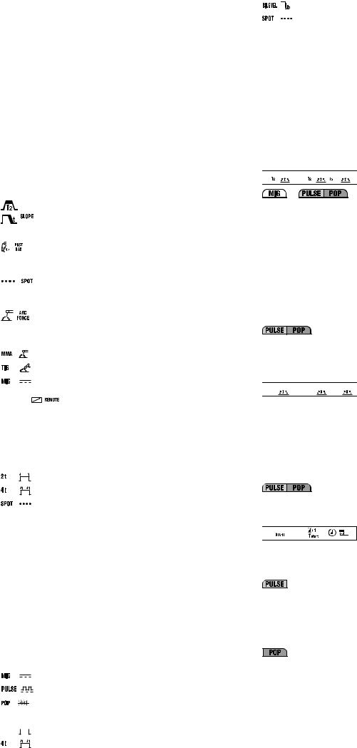
3a, 3b, 3c – LED’s indicating current unit of measurement (amperes, seconds, percentage).
4- Encoder control knob.
Makes it possible to adjust the welding parameters (4a).
: Welding current in TIG/MMA mode.
: In tig mode it is used to reduce the current gradually when the 

 torch button is released (adjustment range 0-3 seconds) and the
LED (3b) on.
: In TIG mode this parameter corresponds to “Post-gas”, and is used to adjust the time for which protective gas will flow after welding stops (adjustment range 0.1-10 seconds and LED (3b) on).
: This is enabled only and exclusively if the “SPOT” mode has been selected with key (7). It is used for TIG spot welding with welding time control (adjustment range 0.1-10 seconds and LED (3b) on).
: With MMA electrode operation, the parameter takes the value of “;Arc force”, so that it is possible to make the setting for dynamic
overcurrent (adjustment range 0-100% and LED (3c) on).
5- Key for selecting welding procedure.
When this key is pressed the LED corresponding to the intended welding mode will light up:
: |
MMA” coated electrode |
: TIG-DC with arc striking at contact (LIFT-ARC). |
|
: |
MIG. |
6- Key for switching on the remote control. |
|
With LED |
on, adjustments can only be by remote control i.e.: |
a)Single potentiometer control: it is used to adjust the welding current in TIG/ MMA mode.
b)Control by two potentiometers: it is used to adjust the TIG/MMA welding current and adjust the SLOPE DOWN in TIG or ARC FORCE in MMA (automatic LED parameter selection).
c)Pedal control: it is used to adjust the welding current in TIG/MMA mode. NOTE: It is only possible to select REMOTE if a remote control is actually connected to the socket.
7- Key for selecting TIG torch button control mode.
Pressing the key lights up the LED that corresponds to:
: 2-stroke operation, ON-OFF with pushbutton pressed.
: 4-stroke operation, ON-OFF with pushbutton released.
: TIG spot welding.
4.2.1 CONTROL PANEL OF THE WIRE FEEDER (FIG. D) 1- ALARM signalling LED (machine output is blocked).
Resetting is automatic when the reason for alarm activation has ceased. Exclusive alarm messages indicated on displays (15) and (16):
-“AL7” : overcurrent safeguard intervention during MIG-MAG welding.
-“AL8” : serial line fault: torch is shorting.
For the remaining messages refer to “WELDING MACHINE CONTROL PANEL” (par. 4.2).
2- VOLTAGE PRESENT IN THE TORCH OR AT THE ELECTRODE signalling LED.
3- WELDING MACHINE PROGRAMMING signalling LED.
4 - RECALL key of the personalised welding programs (see section 4.3.2.4). 5- SAVE key of the personalised welding programs (see section 4.3.2.3). 6- Welding program selection key and 2 digit display.
The display shows the numbers between “0” and “36” when the key is pressed in succession. A synergic welding program is associated with each number from “1” to “36” (see TAB. 3) while manual operation of the welding machine is associated with the number “0”, in which all the parameters can be set by the operator (only in MIG-MAG short and spray arc).
7- Welding procedure selection key.
When this key is pressed the LED corresponding to the intended welding mode will light up:
: MIG-MAG with “SHORT/SPRAY ARC” mode.
: MIG-MAG with “PULSE ARC” mode.
: MIG-MAG with “PULSE ON PULSE” mode.
8- Key for selecting MIG-MAG torch button control mode.
When this key is pressed the LED will light up corresponding to: 

 : 2- stroke operation, ON-OFF with button pressed.
: 4- stroke operation, ON-OFF with button released.
: bi-level operation for MIG-MAG, TIG.
: MIG-MAG (SPOT) welding.
9- Key for switching on remote control.
When LED 

 is on, adjustments can only be made by remote control, i.e.:
-control by two potentiometers: replaces the function of encoder knobs (14) and (13).
NOTE: It is only possible to select REMOTE if a remote control is actually connected to the corresponding socket.
10Key for selecting welding parameters.
Pressing the key repeatedly will light up one of the LED’s from (10a) to (10h), each associated with a specific parameter. Settings of the value of each activated parameter can be carried out using the knob (13) and shown on the display (15). During these settings the knob (14) adjusts the main welding level shown on the display (16) either current or wire feed rate (see description at point (14)), except for (10b).
Knob (14) can only be used to adjust the secondary level when LED (10b) is on (see description of LED (10b)).
Note: Parameters that cannot be modified by the operator, depending on whether you are working with a synergic programme or in manual mode (“PRG” 0) are automatically excluded so that they cannot be selected; the corresponding LED will not light up.
10a- 


This parameter is displayed automatically during MIG-MAG welding operations, and shows the actual arc voltage (LED (15a) is on).
Adjustments:
 Short arc
When setting a MIG-MAG Short Arc synergic programme this parameter is used to set the correction to be made to the arc length as calculated in synergy (range from -5% to +5%) (LED (15c) on).
In the same mode, setting bi-level mode will cause the parameter to take the value of arc length correction at the main welding level as calculated in synergy as above (range from -5% to +5%) (LED (15c) on).
 Short arc “PRG 0”
Also in MIG-MAG ShortArc mode, manual programming “PRG 0”, this parameter is used to set the actual arc voltage (range 10-40) (LED (15a) on).
In the same mode, setting bi-level mode will cause the parameter to take the value of actual arc length at the main welding level as calculated in synergy as above (range 10-40) (LED (15a) on).
When setting a MIG-MAG Pulse Arc synergic programme this parameter is used to set the correction to be made to the arc length as calculated in synergy (range from -5% to +5%) (LED (15c) on).
In the same mode, setting bi-level, pulse on pulse or Tstart mode will cause the parameter to take the value of arc length correction at the main welding level as calculated in synergy as above (range from -5% to +5%) (LED (15c) on).
10b- 


 Short arc
For synergic MIG-MAG short arc programmes, setting bi-level mode will make it possible to adjust the current/wire feed rate (using knob (14)) and to correct arc length (using knob (13)) for the secondary welding level as calculated in synergy (range from -5% to +5%) (LED (15c) on).
 Short arc “PRG 0”
When manual programming “PRG 0” is selected with bi-level mode, this parameter is used to adjust wire feed rate (using knob (14), (LED 16c) on) and actual arc voltage (using knob (13)) for the secondary welding level I1 (range 1040) ((LED (15a) on).
In MIG-MAG pulse arc mode, setting bi-level, pulse on pulse or Tstart mode will enable adjustment of currents I1 and IS (Istart) (using knob (14)) and correction of arc length (using knob (13)) for the secondary welding level, as calculated in synergy (range from -5% to +5%)(LED (15c) on).).
10c- 


 Short arc “PRG 0”
In manual mode, “PRG 0”, this parameter is used to adjust wire feed rate as welding starts, in order to optimise arc strike (adjustment 1-100% and LED (15c) on).
In MIG-MAG Pulse Arc 2-STROKE mode this parameter is used to adjust the length of start current time (Tstart). If the parameter is set to zero, the function is disabled, while with any setting greater than zero (adjustment range 0.1- 3 seconds) it is possible to select LED (10b) in order to set the arc voltage correction and the start current value (secondary level). The start current can be set at a higher or lower value than the main welding value; a higher start current is very useful, especially when welding aluminium and its alloys, making it possible to heat the piece more quickly (“Hot start”).
In MIG-MAG Pulse on Pulse mode the parameter can be used to adjust the length of main welding current time (adjustment range 0.1-10 seconds and LED (15b) on).
10d- 

 Short arc “PRG 0”
In MIG-MAG “PRG 0” manual mode the parameter is used to adjust electronic reactance (adjustment range 20-80% and LED (15c) on). The higher the value, the hotter will be the weld pool. In bi-level mode electronic reactance has the same setting for both levels.
- 7 -

In MIG-MAG pulse arc mode the parameter determines arc pinch-off. The higher the value the more concentrated will be the arc during welding. In a welding mode using two current levels (bi-level, pulse on pulse or Tstart) arc pinch-off has the same setting for both levels (+1% / -1%).
In MIG-MAG Pulse on Pulse mode the parameter can be used to adjust the duration of secondary welding current (adjustment range 0.1-10 seconds and LED (15b) on).
10e-
Wire BURN-BACK time when welding stops.
This parameter is used to adjust wire burn-back time at the end of welding.
When setting a MIG-MAG synergic programme this parameter is used to set the correction to be made to BURN-BACK TIME as calculated in synergy (range from -1% to +1%, LED (15c) on).
 Short arc “PRG 0”
An appropriate setting will prevent the wire from sticking to the piece in manual mode (adjustment range 0.001-1 seconds and LED (15b) on).
10f-
Post-gas
It allows adjusting the time for which protective gas will flow after welding stops (adjustment range 0.1-10 seconds and LED (15b) on).
10g-
Welding current SLOPE DOWN.
This is enabled only and exclusively when using MIG-MAG SHORT ARC, PULSE ARC and PULSE on PULSE synergic programmes.
It is used to reduce the current gradually when the torch button is released (adjustment range 0-3 seconds and LED (15b) on).
10h-
SPOT WELDING TIME.
This is enabled only and exclusively if “SPOT” mode has been selected with key
(8). It is used for MIG-MAG spot welding, with welding time control (adjustment range 0.1-10 seconds and LED (15b) on).
11Key for manual activation of gas solenoid valve.
This button causes gas outflow (piping discharge – flow rate adjustment) without having to operate the torch button; the action of the button is momentary.
12Key for manual wire feed.
This button is used to feed the wire along the torch hose without having to operate the torch button; the action is momentary and feed rate is fixed.
13Encoder knob for adjusting welding parameters (see 10a-10h). 14Encoder knob.
The knob adjusts:
-Welding current I2 (LED (16a) on).
-The wire feed rate (LED (16c) on)
-The thickness of the piece used in welding (LED (16b) on)
In a welding mode using two current levels (bi-level, pulse on pulse or Tstart), with LED (10b) on the knob adjusts:
-Welding current I1 (LED (16a) on) for the secondary level.
-Wire feed rate for the secondary welding level (LED (16c) on).
-The thickness of the piece used in welding (LED (16b) on) for the secondary
level.
15- 3-digit alphanumeric display. This shows:
-welding parameter values (see from (10a) to (10h)) in no-load operation.
-the actual arc voltage during welding.
NOTE: when welding stops, the display automatically switches to the setting value.
- an alarm indicator (see point 1).
15a, 15b, 15cLED’s indicating current unit of measurement (volts, seconds, percentage).
16- 3-digit alphanumeric display. This shows:
-the value of the setting made using the encoder knob (14).
-the actual current during welding.
NOTE: when welding stops, the display automatically switches to the setting value.
- an alarm indicator (see point 1).
16a, 16b, 16cLED’s indicating current unit of measurement (current in amps (A), thickness in millimetres (mm) and wire feed rate metres/minute (m/min)).
17Key for selecting unit of measurement - Amps/Thickness in m/min (LED’s (16a)(16b) (16c)).
In synergic MIG/MAG programs it is used to set weld material thickness, welding current and wire feed rate respectively, using the encoder (14).
The setting for each individual parameter (e.g. material thickness) automatically defines the values of the other parameters (e.g. welding current and wire feed rate).
In “PRG 0” manual selection: it is only possible to adjust the wire feed rate (LED
(16c) on).
4.3 RECALLING AND STORING PROGRAMS
4.3.1 RECALLING MANUFACTURER’S PRE-STORED PROGRAMS 4.3.1.1 MIG-MAG SYNERGIC programs
The welding machine is designed with 36 stored synergic programs, as specified in the table (TAB.3), which must be consulted when selecting a suitable program for the type of welding to be carried out.
A particular program is selected by pressing the “PRG” program repeatedly and the corresponding number, between “0” and “36” will be shown on the display (the number “0” does not have a corresponding synergic program but is for operating in manual mode, as described in the next paragraph).
Note: In a synergic program, it is essential to first select the desired transfer mode, PULSE ARC or SHORT/SPRAY ARC, using the appropriate key (see FIG. D (7)).
Note: All types of wire that are not shown in the table can be used in manual
mode “PRG 0”.
4.3.1.2 OPERATION IN MANUAL MODE (“PRG 0”)
Operation in manual mode corresponds to the number “0” on the display and is only active if the SHORT/SPRAY ARC transfer mode has been selected previously (see
FIG. D (7)).
In this mode, as there will be no synergy, the operator should set all welding parameters manually.
Warning! The operator can set all the parameters freely therefore it is possible to set values that are incompatible with a correct welding procedure.
Note: it is NOT possible to use PULSE ARC transfer mode when manual is selected.
4.3.2STORING AND RECALLING CUSTOMISED MIG-MAG PROGRAMS
4.3.2.1Introduction
The welding machine can be used to (SAVE) customised work programs relating to a set of valid parameters for a particular welding job. Each stored program can be recalled (RECALL) at any time so that the user finds the welding machine “ready-to- use” for a specific job that has been optimised previously.
4.3.2.2 Saving of personalised programs in MIG-MAG
The welding machine can save 40 personalised programs that refer to the three synergy transfer modes (SHORT/SPRAY ARC Pulse arc and Pulse on pulse) and to operation in the manual mode, with the following specifications:
-SYNERGIC SHORT/SPRAY ARC: 10 programs that can be saved (numbers available from “1” to “10”)
-MANUAL SHORT/SPRAY ARC (“PRG=0”): 10 programs that can be saved (numbers available from “1” to “10”)
-SYNERGIC PULSE ARC: 10 programs that can be saved (numbers available from “1” to “10”)
-SYNERGIC PULSE ARC PULSE ON PULSE: 10 programs that can be saved (numbers available from “1” to “10”).
NOTE: To call the program to be used:
a)select the required transfer mode PULSE ARC, PULSE ARC PULSE-ON- PULSE or SHORT/SPRAY ARC or select “PRG=0” if the programs are saved in the manual mode;
b)select the number of the program (as described in section 4.3.1)
4.3.2.3 Storage procedure (SAVE)
After adjusting the welding machine to carry out a particular weld perfectly, proceed as follows (see FIG. D):
a)Press key (5) “SAVE”.
b)“Pr” will appear on display (16) and a number (between “1” and “10”) on display
(15).
c)Turn the encoder knob (either (13) or (14)) to select the number where the program is to be stored (see also 4.3.2 ).
d)Press the “SAVE” key again.
e)Displays (15) and (16) will flash.
f)Within two seconds, press the “SAVE” key again.
g)The displays will show “St Pr”, indicating that the program has been stored; after 2 seconds the displays will automatically switch to the values relating to the parameters that have just been saved.
Note. If the “SAVE” key is not pressed again within 2 seconds while the displays are flashing, they will show “No St” and the program will not be stored; the displays automatically return to what they were showing initially.
4.3.2.4 Procedure for recalling a customised program (RECALL)
Before proceeding to recall a program, make sure the selected transfer mode (PULSE ARC, PULSE ARC PULSE-ON-PULSE, SHORT/SPRY ARC or ”PRG=0”) is actually the one you intend to use.
Then proceed as follows (see FIG. D):
a)Press the “RECALL” key.
b)“Pr” appears on display (16) and a number (between “1” and “10”) on display (15).
c)Turn the encoder knob (either (13) or (14)) to select the number used to save the program that is to be used.
d)Press the “RECALL” key again for more than 2 seconds.
e)The displays will show “Ld Pr” indicating that the program has been loaded; after 2 seconds the displays will automatically switch to the values relating to the program that has just been recalled.
Note. If the “RECALL” key is not pressed again for longer than 2 seconds, the displays will show “No Ld” and the program will not be loaded; the displays automatically return to what they were showing initially.
NOTES:
-DURING OPERATIONS WITH THE “SAVE” AND “RECALL” KEYS THE “PRG” LED IS ON.
-A RECALLED PROGRAM CAN BE MODIFIED AS THE OPERATOR WISHES, BUT THE MODIFIED VALUES ARE NOT AUTOMATICALLY SAVED. TO SAVE THE NEW VALUES IN THE SAME PROGRAM IT IS NECESSARY TO FOLLOW THE STORAGE PROCEDURE (see 4.3.2.3).
-THE USER IS RESPONSIBLE FOR RECORDING CUSTOMISED PROGRAMS AND THE RELATED MANAGING OF THE ASSOCIATED PARAMETERS.
-CUSTOMISED PROGRAMS CANNOT BE SAVED IN TIG OR MMA ELECTRODE MODE.
5.INSTALLATION
WARNING! CARRY OUT ALL INSTALLATION OPERATIONS AND ELECTRICAL CONNECTIONS WITH THE WELDING MACHINE COMPLETELY SWITCHED OFF AND DISCONNECTED FROM THE
POWER SUPPLY OUTLET.
THE ELECTRICAL CONNECTIONS MUST BE MADE ONLY AND EXCLUSIVELY BY AUTHORISED OR QUALIFIED PERSONNEL.
5.1 UNPACKING
-Unpack the trolley and assemble as indicated in the supplied instructions.
-Unpack the welding machine, the wire feeder, and the cooling group if present; install on the trolley
NOTE: Insert the polarisation connector if the GRA is not connected (FIG. E)
5.2 LIFTING THE WELDING MACHINE OR THE WELDING EQUIPMENT
-he welding machine must be lifted as shown in the figure (FIG. O), with no removable parts that can detach (torch, gas pipes, cables, etc.).
As shown in the illustration, assemble the attachment rings using the two M8x25 screws provided.
Please note: eyelet rings for lifting, with threaded hole M8, are not supplied.
-The welding equipment must be lifted as shown in the figure (FIG. P), with no removable parts that can detach (wire feeder, bottle, cables, remote control) Please note: use all 4 lifting points contemporaneously
- 8 -
5.3 POSITION OF THE WELDING MACHINE
Choose the place to install the welding machine so that the cooling air inlets and outlets are not obstructed (forced circulation by fan, if present); at the same time make sure that conductive dusts, corrosive vapours, humidity etc. will not be sucked into the machine.
Leave at least 250mm free space around the welding machine.
WARNING! Position the welding machine on a flat surface with sufficient carrying capacity for its weight, to prevent it from tipping
or moving hazardously.
5.4CONNECTION TO THE MAIN POWER SUPPLY
5.4.1Note
-Before making any electrical connection, make sure the rating data of the welding machine correspond to the mains voltage and frequency available at the place of installation.
-The welding machine should only be connected to a power supply system with the neutral conductor connected to earth.
-To ensure protection against indirect contact use residual current devices of the following types:
-Type A ( 

 ) for single phase machines;
-Type B ( 


 ) for 3-phase machines.
-To comply with the requirements of the EN 61000-3-11 (Flicker) standard we recommend connecting the welding machine to interface points of the power supply that have an impedance of less than Zmax = 0.283 ohm.
-The welding machine does not fall within the requisites of IEC/EN 61000-3-12 standard.
Should it be connected to a public mains system, it is the installer’s responsibility to verify that the welding machine itself is suitable for connecting to it (if necessary, consult the distribution network company).
5.4.2 Plug and outlet
Connect a normalised plug (3P + T) having sufficient capacity to the power cable and prepare a mains outlet fitted with fuses or an automatic circuit-breaker; the special earth terminal should be connected to the earth conductor (yellow-green) of the power supply line. The table (TAB.1) shows the recommended delayed fuse sizes in amps, chosen according to the max. nominal current supplied by the welding machine, and the nominal voltage of the main power supply.
5.5 CONNECTION OF THE WELDING CABLES
WARNING! BEFORE MAKING THE FOLLOWING CONNECTIONS MAKE SURE THE WELDING MACHINE IS SWITCHED OFF AND DISCONNECTED FROM THE POWER SUPPLY OUTLET.
Table (TAB. 1) gives the recommended values for the welding cables (in mm2) .
5.5.1 MIG-MAG WIRE WELDING (FIG.F)
5.5.1.1 Connecting the gas bottle
-Screw the pressure reducing valve onto the gas bottle, inserting the appropriate adapter supplied as an accessory when Argon or an Ar/CO2 mixture is used.
-Connect the gas inlet hose to the pressure reducing valve and tighten the supplied clip; then connect the other end of the hose to the connector provided on the back of the welding machine and tighten it with the supplied clip.
-Loosen the adjustment ring nut on the pressure reducing valve before opening the gas bottle valve.
5.5.1.2Connecting the torch
-Engage the torch with its dedicated connector by tightening the locking ring nut manually as far down as it will go.
-Prepare the wire for loading the first time, by dismantling the nozzle and the contact tip, to ease its exit.
-Welding power supply cable to the quick connector (+).
-Control cable to the corresponding connector.
-Water pipes for R.A. versions (water-cooled torch) with quick connectors.
-Make sure that the connectors are tightened properly so as to prevent overheating and reduced efficiency.
-Connect the gas inlet hose to the pressure reducing valve and tighten the supplied clip; then connect the other end of the hose to the connector provided on the back of the welding machine and tighten it with the supplied clip.
5.5.1.3Connecting the welding current return cable
-This is connected to the piece being welded or to the metal bench supporting it, as close as possible to the join being made.
-This cable is connected to the terminal with the symbol (-).
5.5.2 TIG WELDING (FIG. G)
5.5.2.1Connection to the gas bottle
-Screw the pressure reducing valve onto the gas bottle valve, inserting the appropriate adapter supplied as an accessory, for when the gas used is Argon or an Argon /CO2 mixture.
-Connect the gas inlet pipe to the pressure-reducing valve and tighten the band supplied; then connect the other end of the pipe to the connector on the back of the welding machine and tighten it using the band supplied.
-Loosen the adjustment ring nut on the pressure-reducing valve before opening the bottle valve.
5.5.2.2Connecting the welding current return cable
-This is connected to the piece being welded or to the metal bench supporting it, as close as possible to the join being made.
-This cable is connected to the terminal with the symbol (+).
5.5.2.3Connecting the torch
-Connect the TIG torch to the quick connection (-) on the front panel of the welding machine; complete the connection of the gas pipe and torch control cable.
5.5.3 MMA WELDING WITH COATED ELECTRODE (FIG. H) 5.5.3.1 Connecting the electrode-holder clamp
Practically all coated electrodes are connected to the positive pole (+) of the power source; as an exception, electrodes with an acid coating are connected to the negative pole (-).
Connect the electrode holder clamp cable to the quick connector (+) on the front panel. Note: In some cases, (-) polarity is recommended for the electrode holder clamp, so check the electrode manufacturer’s instructions.
5.5.3.2 Connecting the welding current return cable
-This is connected to the piece being welded or to the metal bench supporting it, as close as possible to the join being made.
-This cable is connected to the terminal with the symbol (-).
5.5.4 WARNINGS
-Turn the welding cable connectors right down into the quick connections , to ensure a perfect electrical contact; otherwise the connectors themselves will overheat, resulting in their rapid deterioration and loss of efficiency.
-The welding cables should be as short as possible.
-Do not use metal structures which are not part of the workpiece to substitute the return cable of the welding current: this could jeopardise safety and result in poor welding.
5.6 LOADING THE WIRE REEL (FIG. I)
WARNING! BEFORE STARTING THE OPERATIONS TO LOAD THE WIRE MAKE SURE THE WELDING MACHINE IS SWITCHED OFF AND DISCONNECTED FROM THE MAIN POWER SUPPLY OUTLET.
MAKE SURE THAT THE WIRE FEEDER ROLLERS, THE WIRE GUIDE HOSE AND THE CONTACT TIP OF THE TORCH MATCH THE DIAMETER AND TYPE OF WIRE TO BE USED AND MAKE SURE THAT THESE ARE FITTED CORRECTLY. WHEN INSERTING AND THREADING THE WIRE DO NOT WEAR PROTECTIVE GLOVES.
-Open the reel compartment door.
-Position the wire reel on the spindle, holding the end of the wire upwards; make sure the tab for pulling the spindle is correctly seated in its hole (1a).
-Release the pressure counter-roller/s and move it/them away from the lower roller/s (2a).
-Make sure the puller roller is suitable for the wire being used (2b).
-Free the end of the wire and remove the distorted end with a clean cut and no burr; turn the reel anti-clockwise and thread the end of the wire into the wire-guide infeed, pushing it 50-100mm into the wire guide of the torch fitting (2c).
-Re-position the counter-roller/s, adjusting the pressure to an intermediate value, and make sure that the wire is correctly positioned in the groove of the lower roller
(3).
-Use the adjustment screw located at the centre of the spindle to apply a slight braking pressure on the spindle itself (1b).
-Remove the nozzle and contact tip (4a).
-Insert the welding machine plug in the power supply outlet, switch on the welding machine, press the torch button and wait for the end of the wire to pass through the whole of the wire guide hose and protrude by 10-15 cm from the front part of the torch, release the button.
WARNING! During these operations the wire is live and subject to mechanical stress; therefore if adequate precautions are not taken the wire could cause hazardous electric shock, injury and striking of
electric arcs:
-Do not direct the mouthpiece of the torch towards parts of the body.
-Keep the torch away from the gas bottle.
-Re-fit the contact tip and the nozzle onto the torch (4b).
-Check that wire feed is regular; set the roller and spindle braking pressure to the minimum possible values making sure that the wire does not slide in the groove and when feed is halted the loops of wire are not loosened by excessive reel inertia.
-Cut the end of the wire so that 10-15 mm protrude from the nozzle.
-Close the reel compartment door.
5.7REPLACING THE LINER IN THE TORCH (FIG. L)
Before proceeding to replace the hose, lay out the torch cable straight without any bends.
5.7.1 Coiled hose for steel wires
1- Unscrew the nozzle and contact tip on the torch head.
2- Unscrew the hose locking nut on the central connector and remove the old hose. 3- Insert the new hose into the cable-torch duct and push it gently until it comes out
of the torch head.
4- Tighten up the hose locking nut by hand.
5- Trim off all the excess protruding hose pressing it slightly; remove it from the torch cable again.
6- Smooth the part where the hose was cut and reinsert it into the cable-torch duct. 7- Tighten up the nut again using a spanner.
8- Reassemble the contact tip and nozzle.
5.7.2 Synthetic hose for aluminium wires
Carry out operations 1, 2, 3 as given for the steel hose (ignore operations 4, 5, 6, 7, 8). 9- Re-tighten the contact tip for aluminium, making sure it comes into contact with the
hose.
10At the other end of the hose (torch connector end) insert the brass nipple and the OR ring and, keeping slight pressure on the hose, tighten the hose locking nut. The excess part of the hose will be removed to size later on (see (13)).
Extract the capillary pipe for steel hoses from the wire feeder torch connector. 11THE CAPILLARY PIPE IS NOT REQUIRED for aluminium hoses of diameter 1.6-
2.4mm (coloured yellow); the hose is therefore inserted into the torch connector without it.
Cut the capillary pipe for aluminium hoses of diameter 1-1.2mm (coloured red) to approx. 2mm shorter than the steel pipe, and insert it into the free end of the hose.
12Insert and lock the torch into the wire feeder connector, mark the hose at 1-2mm from the rollers, take the torch out again.
13Cut the hose to the required size, without distorting the inlet hole.
Reassemble the torch in the wire feeder connector and assemble the gas nozzle.
6. WELDING: DESCRIPTION OF THE PROCEDURE
6.1 MIG-MAG WELDING
6.1.1 SHORT ARC TRANSFER MODE
The melting of the electrode wire and the detachment of the drop is produced by repeated short circuits (up to 200 times per second) from the tip of the wire to the molten pool.
Carbon and mild steels |
0.6-1.2mm |
|
- |
Suitable wire diameter: |
|
- |
Welding current range: |
40-210A |
- |
Arc voltage range: |
14-23V |
- |
Suitable gases: |
CO2 , mix Ar/CO2 , Ar/CO2 /O2 |
Stainless steels |
0.8-1mm |
|
- |
Suitable wire diameter: |
|
- |
Welding current range: |
40-160A |
- |
Arc voltage range: |
14-20V |
- 9 -

- |
Suitable gases: |
mix Ar/O2 , Ar/CO2 (1-2%) |
Aluminium and alloys |
0.8-1.6mm |
|
- |
Suitable wire diameter: |
|
- |
Welding current range: |
75-160A |
- |
Arc voltage range: |
16-22V |
- |
Suitable gases: |
Ar 99.9% |
Generally, the contact tip should be flush with the nozzle or protrude slightly when using the thinnest wires and lowest arc voltages; the length of free wire (stick-out) will normally be between 5 and 12mm.
In MANUAL MODE (“PRG 0”) adjust the reactance value:
-5%-60% with carbon steel wires of diameter 0.8-1mm.
-50%-80% with carbon steel wires of diameter 1.2-1.6mm.
-60%-80% with stainless steel and aluminium wires.
Application: Welding in all positions, on thin material or for the first passage in bevelled edges, with the advantage of limited heat transfer and highly controllable pool.
Note: SHORT ARC transfer for welding aluminium and alloys should be used with great care (especially with wires of diameter >1mm) because the risk of melting defects may arise.
6.1.2 SPRAY ARC TRANSFER MODE
Higher voltages and currents than for ”short arc” are used here to achieve the melting of the wire. The wire tip does not come into contact with the molten pool; an arc forms from the tip and through it flows a stream of metallic droplets. These are produeced by the continuous melting of the electrode wire without short-circuits involved.
Carbon and mild steels |
0.8-1.6mm |
|
- |
Suitable wire diameter: |
|
- |
Welding current range: |
180-450A |
- |
Arc voltage range: |
24-40V |
- |
Suitable gases: |
mix Ar/CO2 , Ar/CO2 /O2 |
Stainless steels |
1-1.6mm |
|
- |
Suitable wire diameter: |
|
- |
Welding current range: |
140-390A |
- |
Welding voltage range: |
22-32V |
- |
Suitable gases: |
mix Ar/O2 , Ar/CO2 (1-2%) |
Aluminium and alloys |
0.8-1.6mm |
|
- |
Suitable wire diameter: |
|
- |
Welding current range: |
120-360A |
- |
welding voltage range: |
24-30V |
- |
suitable gases: |
Ar 99.9% |
The contact tip should generally be 5-10mm inside the nozzle, the higher the arc voltage the further inside; the length of free wire (stick-out) should normally be between 10 and 12mm.
In MANUAL MODE (“PRG 0”), once the wire feed rate and arc voltage parameters have been selected correctly (i.e. with compatible values), the selected value of the reactance is immaterial.
Application: Horizontal welding with thicknesses of at least 3-4mm (very fluid pool); execution rate and deposit rate are very high (high heat transfer).
6.1.3 PULSE ARC TRANSFER MODE
This is a “controlled” transfer situated in the “spray arc” transfer area (modified spray arc) and therefore has the advantages of speedy melting and lack of projections, extending to significantly low current values so as to satisfy many typical “short arc” applications as well.
Every current impulse corresponds to the separation of a single drop from the wire electrode; the phenomenon occurs with a frequency that is proportional to the wire feed rate with the variation rule related to the type and diameter of the wire itself (typical frequency values: 30-300Hz).
Carbon and mild steels |
0.8-1.6mm |
|
- |
Suitable wire diameter: |
|
- |
Welding current range: |
60-360A |
- |
Arc voltage range: |
18-32V |
- |
Suitable gases: |
mix Ar/CO2 , Ar/CO2 /O2 (Co2 max 20%) |
Stainless steels |
0.8-1.2mm |
|
- |
Suitable wire diameter: |
|
- |
Welding current range: |
50-230A |
- |
Welding voltage range: |
17-26V |
- |
Suitable gases: |
mix Ar/O2 , Ar/CO2 (1-2%) |
Aluminium and alloys |
0.8-1.6mm |
|
- |
Suitable wire diameter: |
|
- |
Welding current range: |
40-320A |
- |
welding voltage range: |
17-28V |
- |
suitable gases: |
Ar 99.9% |
Normally the contact pipe should be 5-10mm inside the nozzle, the higher the arc voltage, the further inside; the length of free wire (stick-out) will normally be between 10 and 12mm.
Application: “horizontal” welding on medium-low thicknesses and on heat-sensitive materials, particularly suitable for welding light alloys (aluminium and its alloys) also on thicknesses below 3mm.
6.1.4 ADJUSTING THE WELDING PARAMETERS IN MIG-MAG 6.1.4.1 Protective gas
The gas flow rate should be: short arc: 8-14 l/min
spray arc and pulse arc: 12-20 l/min
depending on welding current intensity and nozzle diameter.
6.1.4.2 Welding current
Welding current is adjusted by the operator by turning the encoder knob (FIG. D (14)). When SPRAY/SHORT ARC is selected, each turn of the encoder knob (14) corresponds to a wire feed rate adjustment (m/minute), which is shown on the display (16); during welding, the display automatically switches to the actual current value (amps).
When PULSE ARC or PULSE ARC PULSE-ON-PULSE is selected, each time the encoder knob (14) is turned this corresponds to an adjustment of welding current, which is shown on the display (16); during welding, the display automatically switches to the actual current value.
In both modes it is possible to press key (17) to pass to regulation of thickness in mm (LED (16b) lit up) using the encoder (14). The machine automatically calculates the current required to weld this thickness. Also in this case the display will switch to the
actual current (amps.) during welding.
It should be pointed out that in all the synergic programs the maximum and minimum values for the settings (m/minute, amps or thickness in mm) are programmed in the factory and cannot be changed by the user.
Indicative values for the current with the most commonly used wires are given in the table (TAB. 4).
6.1.4.3 Arc voltage and Pinch-off
In MIG-MAG pulse-arc and pulse-on-pulse synergy programs (10d) these two parameters determine the dimension of the arc during welding
The arc voltage indicates the distance of the wire from the piece. The discretion margin of the operator is limited to the simple correction from -5% to +5% of the voltage value that is preset in each program to adapt the effective length of the arc for specific needs if necessary. The higher the value the farther the wire from the piece.
In the “PRG 0” manual program the arc voltage is defined by setting a suitable value for the wire feed rate, selected using the formula
U2 = ( 14+0,05 I2 ) where: - U2 = Arc voltage in volts.
- I2 = Welding current in amperes
It must be considered that the loaded voltage (during welding) is to 2-4V less than the selected loadless voltage value.
The pinch-off instead determines the arc concentration or width; the correction range of this parameter goes from -10% to +10% of the program default value. The higher the value, the more concentrated the arc will be.
6.1.5 BI-LEVEL AND PULSE ON PULSE OPERATION
Bi-level operation: Set using key (FIG. D (8)) and can be selected in MIG-MAG pulse arc and short arc modes. The welding cycle begins by pressing and releasing the torch pushbutton (like the 4-stroke), the initial work point of the welding machine is equal to the main welding level (FIG. D (LED (10a)) and the machine shows current and voltage of this work point. Keeping the torch pushbutton pressed for less than 0.5 seconds makes the machine change the work point from the main to the secondary level (FIG. D (LED (10b)), showing the secondary level current and voltage on the display. With each subsequent push of the torch pushbutton, the machine continues passing from one level to another until the pushbutton is kept pressed for longer than 0.5 seconds, starting the down slope of the current thus ending the welding.
During welding, and even if the machine shows the immediate current and voltage values, only the arc current and voltage of the main welding level can be varied.
MIG-MAG Pulse on Pulse operation: can be activated using key (FIG. D (7)) together with the MIG-MAG Pulse arc LED. This is a special type of bi-level mode because also in this case we have two work points set with the same criteria as the bi-level (FIG. D (LED (10a) and (10b)). The duration of each level t1 and t2 can both be set (FIG. D (LED (10c) and (10d)) and are not set manually, as happens instead with bi-level. During welding the machine therefore continues switching the working point automatically from the main level (duration t1) to the secondary level (duration t2). The phenomenon created is that of having a pulsation in a pulsation, hence the name. By setting the two levels and the two durations correctly it is possible to obtain wave welding that is very similar to TIG welding
6.2 TIG WELDING (DC)
After making the welding circuit connections as described in section 5.5.2 it is necessary to:
-Select the TIG welding procedure on the welding machine control panel (FIG.C (5)).
-Set the welding current to the desired value using the encoder knob (FIG. C (4)), (the value can always be adjusted during welding as well).If necessary insert the current down slope using the key (FIG. C (4a)) (momentary indication on the display
(FIG. C (3)).
6.2.1 LIFT strike
Place the tip of the electrode on the piece, using slight pressure. Press the torch button right down and lift the electrode by 2-3 mm with a slight delay, so that the arc strikes. The welding machine will first output a base current IBASE, after a few moments the current output will be equal to the welding current setting. At the end of the cycle the current will decrease according to the slope down setting.
Table (TAB. 5) summarises some indicative data for welding stainless or high alloy steel.
6.3 WELDING WITH MMA COATED ELECTRODE
After making the welding circuit connections as described in section 5.5.3 select the MMA procedure using the corresponding button (FIG. C (5)):
Set the welding current to the desired value using the encoder knob (FIG. C (4)) and any possible “ARC FORCE” dynamic overcurrent can be varied from between 0 and 100% using the encoder knob (FIG. C (4)), with a momentary indication of the value on the display (FIG. C (3)).
The table (TAB. 6) summarises some indicative values for the current in relation to electrode diameter.
6.4 WELD QUALITY
The quality of the weld seam, and the amount of spatter, is mainly determined by the balance of the welding parameters: current (wire feed rate), wire diameter, arc voltage etc.
In addition, the position of the torch should be adjusted as shown in Fig. M, to prevent excessive spray production and flaws in the seam.
The welding rate (i.e. advancement speed along the join) should also be taken into consideration. This is a determining factor for correct penetration and for the shape of the seam itself.
The most common welding flaws are summarised in the table (TAB. 7).
7. MAINTENANCE
WARNING! BEFORE CARRYING OUT MAINTENANCE OPERATIONS MAKE SURE THE WELDING MACHINE IS SWITCHED OFF AND DISCONNECTED FROM THE MAIN POWER SUPPLY.
7.1 ROUTINE MAINTENANCE
ROUTINE MAINTENANCE OPERATIONS CAN BE CARRIED OUT BY THE OPERATOR.
7.1.1.Torch
-Do not put the torch or its cable on hot pieces; this would cause the insulating materials to melt, making the torch unusable after a very short time.
-Make regular checks on the gas pipe and connector seals.
-Every time the wire reel is changed, blow out the wire-guide hose using dry compressed air (max. 5bar) to make sure it is not damaged.
-At least once a day, check the wear and correct assembly of the parts at the end of the torch: nozzle, contact tip, gas diffuser.
7.1.2Wire feeder
-Make frequent checks on the state of wear of the wire feeder rollers, regularly
- 10 -
remove the metal dust deposited in the feeder area (rollers and wire-guide infeed and outfeed).
7.2 EXTRAORDINARY MAINTENANCE
EXTRAORDINARY MAINTENANCE OPERATIONS SHOULD BE CARRIED OUT ONLY AND EXCLUSIVELY BY SKILLED OR AUTHORISED ELECTRICALMECHANICAL TECHNICIANS.
WARNING! BEFORE REMOVING THE WELDING MACHINE PANELS AND WORKING INSIDE THE MACHINE MAKE SURE THE WELDING MACHINE IS SWITCHED OFF AND DISCONNECTED FROM THE MAIN
POWER SUPPLY OUTLET.
If checks are made inside the welding machine while it is live, this may cause serious electric shock due to direct contact with live parts and/or injury due to direct contact with moving parts.
-Periodically, and in any case with a frequency in keeping with the utilisation and with the environment’s dust conditions, inspect the inside of the welding machine and remove the dust deposited on the electronic boards with a very soft brush or with appropriate solvents.
-At the same time make sure the electrical connections are tight and check the wiring for damage to the insulation.
-At the end of these operations re-assemble the panels of the welding machine and screw the fastening screws right down.
-Never, ever carry out welding operations while the welding machine is open.
8. TROUBLESHOOTING (TAB.8)
WARNING! CARRYING OUT CERTAIN CHECKS IMPLIES THE RISK OF CONTACT WITH LIVE AND/OR MOVING PARTS.
IF THE WELDING MACHINE IS NOT WORKING PROPERLY, BEFORE MAKING MORE SYSTEMATIC CHECKS OR CALLING YOUR SERVICING CENTRE MAKE THE FOLLOWING CHECKS:
-Make sure the welding current (adjusted using the encoder) is correct.
-Make sure there is no alarm indicating triggering of the thermal relay or of the overvoltage, undervoltage or short circuit safeguards.
-Make sure you have not exceeded the rated duty cycle; if the thermal cutout has triggered wait until the welding machine has cooled naturally, make sure the fan is working properly.
-Check the main power supply voltage: if it is too low or too high the welding machine will signal this fault (see section 4.2).
-Make sure there is no shorting at welding machine output: in such a case eliminate the problem.
-Make sure the welding circuit connections have been made correctly, in particular that the earth clamp is actually connected to the piece, with no insulating material (e.g. paint) in the way .
-Make sure you are using the right protective gas, and the correct amount.
Before carrying out any work on the wire feeder or inside the welding machine, first consult chapter 7 on “MAINTENANCE”.
- 11 -
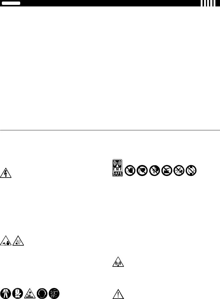
ITALIANO
INDICE
1. SICUREZZA GENERALE PER LA SALDATURA AD ARCO |
pag. |
5.5.1 SALDATURAA FILO MIG-MAG |
pag. |
12 |
16 |
||
2. INTRODUZIONE E DESCRIZIONE GENERALE................................................. |
13 |
5.5.1.1 Collegamento della bombola gas.............................................. |
16 |
2.1 INTRODUZIONE.............................................................................................. |
13 |
5.5.1.2 Collegamento della Torcia......................................................... |
16 |
2.2 SALDABILITÀ DEI METALLI........................................................................... |
13 |
5.5.1.3 Collegamento del cavo di ritorno della corrente di saldatura..... |
16 |
2.3 ACCESSORI DI SERIE................................................................................... |
13 |
5.5.2 SALDATURA TIG................................................................................... |
16 |
2.4 ACCESSORI A RICHIESTA............................................................................. |
13 |
5.5.2.1Collegamento della bombola gas................................................ |
16 |
3. DATI TECNICI....................................................................................................... |
13 |
5.5.2.2 Collegamento del cavo di ritorno della corrente di saldatura..... |
16 |
3.1 TARGA DATI.................................................................................................... |
13 |
5.5.2.3 Collegamento della torcia......................................................... |
16 |
3.2 ALTRI DATI TECNICI....................................................................................... |
13 |
5.5.3 SALDATURA CON ELETTRODO RIVESTITO MMA............................ |
16 |
4. DESCRIZIONE DELLA SALDATRICE................................................................. |
13 |
5.5.3.1 Collegamento della pinza portaelettrodo................................... |
16 |
4.1 DISPOSITIVI DI CONTROLLO, REGOLAZIONE E CONNESSIONE............. |
13 |
5.5.3.2 Collegamento del cavo di ritorno della corrente di saldatura..... |
16 |
4.1.1 Saldatrice............................................................................................... |
13 |
5.5.4 RACCOMANDAZIONI........................................................................... |
16 |
4.1.2 Alimentatore di filo................................................................................. |
13 |
5.6 CARICAMENTO BOBINA FILO...................................................................... |
16 |
4.2 PANNELLO DI CONTROLLO DELLA SALDATRICE...................................... |
14 |
5.7 SOSTITUZIONE DELLA GUAINA GUIDAFILO NELLA TORCIA..................... |
16 |
4.2.1 PANNELLO DI CONTROLLO DELL’ALIMENTATORE DI FILO............. |
14 |
5.7.1 Guaina a spirale per fili acciaio.............................................................. |
16 |
4.3 RICHIAMO E MEMORIZZAZIONE DEI PROGRAMMI................................... |
15 |
5.7.2 Guaina in materiale sintetico per fili alluminio........................................ |
17 |
4.3.1 RICHIAMO PROGRAMMI PREMEMORIZZATI |
|
6. SALDATURA: DESCRIZIONE DEL PROCEDIMENTO....................................... |
17 |
DAL COSTRUTTORE............................................................................ |
15 |
6.1 SALDATURA MIG-MAG................................................................................... |
17 |
4.3.1.1 Programmi MIG-MAG SINERGICI............................................. |
15 |
6.1.1 MODALITÀ DI TRASFERIMENTO SHORT ARC (ARCO CORTO)....... |
17 |
4.3.1.2 FUNZIONAMENTO IN MODALITÀ MANUALE (“PRG 0”)......... |
15 |
6.1.2 MODALITÀ DI TRASF. SPRAY ARC (ARCO A SPRUZZO).................. |
17 |
4.3.2 MEMORIZZAZIONE E RICHIAMO PROGRAMMI |
|
6.1.3 MODALITÀ DI TRASFERIMENTO PULSE ARC (ARCO PULSATO).... |
17 |
PERSONALIZZATI IN MIG-MAG........................................................... |
15 |
6.1.4 REGOLAZIONE DEI PARAMETRI DI SALDATURA IN MIG-MAG....... |
17 |
4.3.2.1 Introduzione............................................................................... |
15 |
6.1.4.1 Gas di protezione....................................................................... |
17 |
4.3.2.2 Capacità di memorizzazione di programmi |
|
6.1.4.2 Corrente di saldatura................................................................. |
17 |
personalizzati in MIG-MAG........................................................ |
15 |
6.1.4.3 Tensione d’arco e Strozzatura d’arco (pinch-off)........................ |
17 |
4.3.2.3 Procedura di memorizzazione (SAVE)....................................... |
15 |
6.1.5 FUNZIONAMENTO BI-LEVEL E PULSE ON PULSE........................... |
17 |
4.3.2.4 Procedura di richiamo di un programma |
|
6.2 SALDATURA TIG (DC).................................................................................... |
17 |
personalizzato (RECALL).......................................................... |
15 |
6.2.1 Innesco LIFT.......................................................................................... |
18 |
5. INSTALLAZIONE.................................................................................................. |
16 |
6.3 SALDATURA CON ELETTRODO RIVESTITO MMA....................................... |
18 |
5.1 ALLESTIMENTO.............................................................................................. |
16 |
6.4 QUALITÀ DELLA SALDATURA....................................................................... |
18 |
5.2 MODALITÀ DI SOLLEVAMENTO DELLA SALDATRICE................................ |
16 |
7. MANUTENZIONE.................................................................................................. |
18 |
5.3 UBICAZIONE DELLA SALDATRICE............................................................... |
16 |
7.1 MANUTENZIONE ORDINARIA....................................................................... |
18 |
5.4 COLLEGAMENTO ALLA RETE....................................................................... |
16 |
7.1.1 Torcia..................................................................................................... |
18 |
5.4.1 Avvertenze............................................................................................. |
16 |
7.1.2 Alimentatore di filo................................................................................. |
18 |
5.4.2 Spina e presa......................................................................................... |
16 |
7.2 MANUTENZIONE STRAORDINARIA.............................................................. |
18 |
5.5 CONNESSIONI CIRCUITO DI SALDATURA................................................... |
16 |
8. ANOMALIE, CAUSE E RIMEDI............................................................................ |
18 |
SALDATRICI A FILO CONTINUO PER LA SALDATURA AD ARCO MIG-MAG E FLUX, TIG, MMA PREVISTE PER USO PROFESSIONALE E INDUSTRIALE. Nota: Nel testo che segue verrà impiegato il termine “saldatrice”.
1. SICUREZZA GENERALE PER LA SALDATURA AD ARCO
L’operatore deve essere sufficientemente edotto sull’uso sicuro della saldatrice ed informato sui rischi connessi ai procedimenti per saldatura ad arco, alle relative misure di protezione ed alle procedure di emergenza.
(Fare riferimento anche alla ”SPECIFICA TECNICA IEC o CLC/TS 62081”: INSTALLAZIONE ED USO DELLE APPARECCHIATURE PER SALDATURA AD ARCO).
-Evitare i contatti diretti con il circuito di saldatura; la tensione a vuoto fornita dalla saldatrice può essere pericolosa in talune circostanze.
-La connessione dei cavi di saldatura, le operazioni di verifica e di riparazione devono essere eseguite a saldatrice spenta e scollegata dalla rete di alimentazione.
-Spegnere la saldatrice e scollegarla dalla rete di alimentazione prima di sostituire i particolari d’usura della torcia.
-Eseguire l’installazione elettrica secondo le previste norme e leggi antinfortunistiche.
-La saldatrice deve essere collegata esclusivamente ad un sistema di alimentazione con conduttore di neutro collegato a terra.
-Assicurarsi che la presa di alimentazione sia correttamente collegata alla terra di protezione.
-Non utilizzare la saldatrice in ambienti umidi o bagnati o sotto la pioggia.
-Non utilizzare cavi con isolamento deteriorato o con connessioni allentate.
-In presenza di una unità di raffreddamento a liquido le operazioni di riempimento devono essere eseguite a saldatrice spenta e scollegata dalla rete di alimentazione.
-Non saldare su contenitori, recipienti o tubazioni che contengano o che abbiano contenuto prodotti infiammabili liquidi o gassosi.
-Evitare di operare su materiali puliti con solventi clorurati o nelle vicinanze di dette sostanze.
-Non saldare su recipienti in pressione.
-Allontanare dall’area di lavoro tutte le sostanze infiammabili (p.es. legno, carta, stracci, etc.).
-Assicurarsi un ricambio d’aria adeguato o di mezzi atti ad asportare i fumi di saldatura nelle vicinanze dell’arco; è necessario un approccio sistematico per la valutazione dei limiti all’esposizione dei fumi di saldatura in funzione della loro composizione, concentrazione e durata dell’esposizione stessa.
-Mantenere la bombola al riparo da fonti di calore, compreso l’irraggiamento solare (se utilizzata).
-Adottare un adeguato isolamento elettrico rispetto l’elettrodo, il pezzo in lavorazione ed eventuali parti metalliche messe a terra poste nelle vicinanze (accessibili).
Ciò è normalmente ottenibile indossando guanti, calzature, copricapo ed indumenti previsti allo scopo e mediante l’uso di pedane o tappeti isolanti.
-Proteggere sempre gli occhi con gli appositi vetri inattinici montati su maschere o caschi.
Usare gli appositi indumenti ignifughi protettivi evitando di esporre l’epidermide ai raggi ultravioletti ed infrarossi prodotti dall’arco; la protezione deve essere estesa ad altre persone nelle vicinanze dell’arco per mezzo di schermi o tende non riflettenti.
-Rumorosità: Se a causa di operazioni di saldatura particolarmente intensive viene verificato un livello di esposizione quotidiana personale (LEPd) uguale o maggiore a 85db(A), è obbligatorio l’uso di adeguati mezzi di protezione individuale.
-Il passaggio della corrente di saldatura provoca l’insorgere di campi elettromagnetici (EMF) localizzati nei dintorni del circuito di saldatura.
I campi elettromagnetici possono interferire con alcune apparecchiature mediche (es. Pace-maker, respiratori, protesi metalliche etc.).
Devono essere prese adeguate misure protettive nei confronti dei portatori di queste apparecchiature. Ad esempio proibire l’accesso all’area di utilizzo della saldatrice.
Questa saldatrice soddisfa gli standard tecnici di prodotto per l’uso esclusivo in ambiente industriale a scopo professionale. Non è assicurata la rispondenza ai limiti di base relativi all’esposizione umana ai campi elettromagnetici in ambiente domestico.
L’operatoredeveutilizzareleseguentiprocedureinmododaridurrel’esposizione ai campi elettromagnetici:
-Fissare insieme il più vicino possibile i due cavi di saldatura.
-Mantenere la testa ed il tronco del corpo il più distante possibile dal circuito di saldatura.
-Non avvolgere mai i cavi di saldatura attorno al corpo.
-Non saldare con il corpo in mezzo al circuito di saldatura. Tenere entrambi i cavi dalla stessa parte del corpo.
-Collegare il cavo di ritorno della corrente di saldatura al pezzo da saldare il più vicino possibile al giunto in esecuzione.
-Non saldare vicino, seduti o appoggiati alla saldatrice (distanza minima: 50cm).
-Non lasciare oggetti ferromagnetici in prossimità del circuito di saldatura.
-Distanza minima d= 20cm (Fig. N).
-Apparecchiatura di classe A:
Questa saldatrice soddisfa i requisiti dello standard tecnico di prodotto per l’uso esclusivo in ambiente industriale e a scopo professionale. Non è assicurata la rispondenza alla compatibilità elettromagnetica negli edifici domestici e in quelli direttamente collegati a una rete di alimentazione a bassa tensione che alimenta gli edifici per l’uso domestico.
PRECAUZIONI SUPPLEMENTARI
-LE OPERAZIONI DI SALDATURA:
-In ambiente a rischio accresciuto di shock elettrico;
-In spazi confinati;
-In presenza di materiali infiammabili o esplodenti.
DEVONO essere preventivamente valutate da un ”Responsabile esperto” ed eseguite sempre con la presenza di altre persone istruite per interventi in
- 12 -
caso di emergenza.
DEVONO essere adottati i mezzi tecnici di protezione descritti in 5.10; A.7; A.9. della “SPECIFICA TECNICA IEC o CLC/TS 62081”.
-DEVE essere proibita la saldatura mentre la saldatrice o l’alimentatore di filo è sostenuto dall’operatore (es. per mezzo di cinghie).
-DEVE essere proibita la saldatura con operatore sollevato da terra, salvo eventuale uso di piattaforme di sicurezza.
-TENSIONE TRA PORTAELETTRODI O TORCE: lavorando con più saldatrici su di un solo pezzo o su più pezzi collegati elettricamente si può generare una somma pericolosa di tensioni a vuoto tra due differenti portaelettrodi o torce, ad un valore che può raggiungere il doppio del limite ammissibile.
E’ necessario che un coordinatore esperto esegua la misura strumentale per determinare se esiste un rischio e possa adottare misure di protezione adeguate come indicato in 5.9 della ”SPECIFICA TECNICA IEC o CLC/TS 62081”.
RISCHI RESIDUI
-RIBALTAMENTO: collocare la saldatrice su una superficie orizzontale di portata adeguata alla massa; in caso contrario (es. pavimentazioni inclinate, sconnesse etc...) esiste il pericolo di ribaltamento.
-E’ vietato il sollevamento dell’assieme carrello con saldatrice, alimentatore di filo e gruppo di raffreddamento (quando presente).
-L’unica modalità di sollevamento AMMESSA è quella prevista nella sezione ”INSTALLAZIONE” di questo manuale.
-USO IMPROPRIO: è pericolosa l’utilizzazione della saldatrice per qualsiasi lavorazione diversa da quella prevista (es. scongelazione di tubazioni della rete idrica).
-SPOSTAMENTO DELLA SALDATRICE E RELATIVO CARRELLO: assicurare sempre la bombola con idonei mezzi atti ad impedirne cadute accidentali.
Le protezioni e le parti mobili dell’involucro della saldatrice e dell’alimentatore di filo devono essere in posizione, prima di collegare la saldatrice alla rete di alimentazione.
ATTENZIONE! Qualunque intervento manuale su parti in movimento dell’alimentatore di filo, ad esempio:
-Sostituzione rulli e/o guidafilo;
-Inserimento del filo nei rulli;
-Caricamento della bobina filo;
-Pulizie dei rulli, degli ingranaggi e della zona sottostante ad essi;
-Lubrificazione degli ingranaggi.
DEVE ESSERE ESEGUITO CON LA SALDATRICE SPENTA E SCOLLEGATA DALLA RETE DI ALIMENTAZIONE.
2. INTRODUZIONE E DESCRIZIONE GENERALE
2.1 INTRODUZIONE
Questa saldatrice è composta da una sorgente di corrente e da un alimentatore di filo integrato. La sorgente di corrente è un raddrizzatore ad alimentazione trifase multiprocedimento (MIG-MAG SINERGICO continuo e pulsato, TIG ed MMA) con regolazione elettronica (switch-mode) controllata a microprocessore, con ponte intero lato primario.
L’alimentatore di filo è provvisto di gruppo trainafilo a 4 rulli motorizzati con regolazione indipendente della pressione di trascinamento; il pannello di controllo digitale è integrato con la scheda di regolazione a microprocessore ed in esso sono fondamentalmente condensate tre funzionalità:
a)IMPOSTAZIONE E REGOLAZIONE DEI PARAMETRI
Mediante questa interfaccia utente è possibile l’impostazione e la regolazione dei parametri operativi, la selezione di programmi memorizzati, la visualizzazione su display delle condizioni di stato e del valore dei parametri.
b)RICHIAMO DI PROGRAMMI SINERGICI PREMEMORIZZATI PER SALDATURA MIG-MAG
Questi programmi sono predefiniti e memorizzati dal costruttore (quindi non modificabili); dopo aver richiamato uno di questi programmi, l’utente può selezionare un determinato punto di lavoro (corrispondente ad un set di diversi parametri indipendenti di saldatura) regolando una sola grandezza. Questo è il concetto di SINERGIA, la quale consente di ottenere con estrema facilità una regolazione ottimale della saldatrice in funzione di ogni specifica condizione operativa.
c)MEMORIZZAZIONE/RICHIAMO DI PROGRAMMI PERSONALIZZATI
Questa funzionalità è disponibile sia lavorando nell’ambito di un programma sinergico, sia in modalità manuale (in questo caso è arbitraria l’impostazione di tutti i parametri di saldatura). Questa operatività consente all’utente di memorizzare e successivamente richiamare una modalità di saldatura prememorizzata.
2.2 SALDABILITÀ DEI METALLI
MIG-MAG La saldatrice è indicata per la saldatura MIG dell’alluminio e delle sue leghe, la brasatura MIG eseguita tipicamente su lamiere zincate e la saldatura MAG degli acciai al carbonio, basso legati ed acciai inox. La saldatura MIG dell’alluminio e delle sue leghe deve essere eseguita utilizzando fili pieni di composizione compatibile con il materiale da saldare e gas di protezione Ar puro (99,9%).
La brasatura MIG è eseguibile tipicamente su lamiere zincate con fili pieni in lega di rame (es. rame silicio o rame alluminio) con gas di protezione Ar puro (99,9%).
La saldatura MAG degli acciai al carbonio e basso legati deve essere eseguita utilizzando fili pieni di composizione compatibile con il materiale da saldare, gas di protezione Co2, miscele Ar/CO2 o Ar/CO2-O2 (Argon tipicamente > 80%).
Per la saldatura degli acciai inox si utilizzano tipicamente miscele di gas Ar/O2 o Ar/ CO2 (Ar tipicamente> 98%).
TIG La saldatrice è indicata per la saldatura TIG in corrente continua (DC) con innesco dell’arco a contatto (modalità LIFT ARC), adatta all’impiego con tutti gli acciai (al carbonio, basso-legati e alto-legati) e dei metalli pesanti (rame, nichel, titanio e loro leghe) con gas di protezione Ar puro (99,9%) oppure, per impieghi particolari, con miscele Argon/Elio.
MMA La saldatrice è indicata per la saldatura ad elettrodo MMA in corrente continua (DC) con tutte le tipologie di elettrodi rivestiti.
2.3 ACCESSORI DI SERIE
-Adattatore bombola ARGON.
-Cavo di ritorno completo di pinza di massa.
-Riduttore di pressione 2 manometri.
-Kit cavi di collegamento 1,5m.
-Gruppo raffreddamento acqua G.R.A. (solo per versione R.A.).
-Torcia MIG
(raffreddata ad acqua nella versione R.A.).
-Alimentatore di filo.
-Kit copribobina.
-Carrello
2.4ACCESSORI A RICHIESTA
-Comando a distanza manuale 1 potenziometro (solo TIG e MMA).
-Comando a distanza manuale 2 potenziometri.
-Comando a distanza a pedale (solo TIG e MMA).
-Gruppo raffreddamento acqua G.R.A. (accessorio di serie solo per versione R.A.).
-Kit cavi di collegamento R.A. 4m, 10m, 30m.
-Kit cavi di collegamento 4 o 10m.
-Kit ruote alimentatore di filo.
-Kit saldatura alluminio.
-Kit saldatura filo animato.
-Kit saldatura MMA 600A.
- Torcia MIG 5m 500A.
-Torcia MIG 3m 500A R.A.
(accessorio di serie solo per versione R.A.).
- |
Torcia MIG 5m 500A R.A. |
|||||
- |
Torcia |
TIG |
4 |
o |
8m, |
220A. |
- |
Torcia |
TIG |
4 |
o |
8m |
350A R.A. |
-Torcia MIG/TIG UP/DOWN con/senza potenziometro.
-Torcia PUSH PULL.
-Torcia con seriale 485.
-Kit doppia bombola.
3.DATI TECNICI
3.1 TARGA DATI (FIG. A)
I principali dati relativi all’impiego e alle prestazioni della saldatrice sono riassunti nella targa caratteristiche col seguente significato:
1- Grado di protezione dell’involucro.
2- Simbolo della linea di alimentazione: 1~: tensione alternata monofase; 3~: tensione alternata trifase.
3- Simbolo S: indica che possono essere eseguite operazioni di saldatura in un ambiente con rischio accresciuto di shock elettrico (es. in stretta vicinanza di grandi masse metalliche).
4- Simbolo del procedimento di saldatura previsto.
5- Simbolo della struttura interna della saldatrice.
6- Norma EUROPEA di riferimento per la sicurezza e la costruzione delle macchine per saldatura ad arco.
7- Numero di matricola per l’identificazione della saldatrice (indispensabile per assistenza tecnica, richiesta ricambi, ricerca origine del prodotto).
8- Prestazioni del circuito di saldatura:
-U0 : tensione massima a vuoto (circuito di saldatura aperto).
-I2/U2: Corrente e tensione corrispondente normalizzata che possono venire erogate dalla saldatrice durante la saldatura.
-X : Rapporto d’intermittenza: indica il tempo durante il quale la saldatrice può erogare la corrente corrispondente (stessa colonna). Si esprime in %, sulla base di un ciclo di 10 minuti (es. 60% = 6 minuti di lavoro, 4 minuti sosta e così via). Nel caso i fattori d’utilizzo (riferiti a 40°C ambiente) vengano superati, si determinerà l’intervento della protezione termica (la saldatrice rimane in standby finché la sua temperatura non rientra nei limiti ammessi).
-A/V-A/V: Indica la gamma di regolazione della corrente di saldatura (minimo - massimo) alla corrispondente tensione d’arco.
9- Dati caratteristici della linea di alimentazione: |
della saldatrice(limiti |
|||
- U1: Tensione alternata e frequenza di alimentazione |
||||
|
ammessi ±10%): |
|
||
- I1 max: Corrente massima assorbita dalla linea. |
|
|||
- |
I |
: |
Corrente effettiva di alimentazione. |
da prevedere per la |
10- |
1eff |
|
: Valore dei fusibili ad azionamento ritardato |
|
protezione della linea.
11-Simboli riferiti a norme di sicurezza il cui significato è riportato nel capitolo 1 “Sicurezza generale per la saldatura ad arco”.
Nota: L’esempio di targa riportato è indicativo del significato dei simboli e delle cifre; i valori esatti dei dati tecnici della saldatrice devono essere rilevati direttamente sulla targa della saldatrice stessa.
3.2 ALTRI DATI TECNICI: |
vedi tabella (TAB.1) |
||
- |
SALDATRICE: |
||
- |
TORCIA: |
vedi tabella |
(TAB.2A) |
- |
ALIMENTATORE DI FILO: |
vedi tabella |
(TAB.2B) |
4. DESCRIZIONE DELLA SALDATRICE
4.1 DISPOSITIVI DI CONTROLLO, REGOLAZIONE E CONNESSIONE 4.1.1 Saldatrice (FIG. B1)
sul lato anteriore:
1- Pannello di controllo (vedi descrizione).
2- Presa rapida negativa (-) per cavo corrente di saldatura (cavo di massa per MIG ed MMA, cavo torcia per TIG).
3- Raccordo gas per torcia TIG.
4- Connettore 3p per cavo controllo TORCIA TIG.
5- Connettore a 14p per collegamento del comando a distanza (a richiesta). 6- Presa rapida positivo (+) per cavo di massa saldatura TIG.
sul lato posteriore :
7- Interruttore generale ON/OFF.
8- Attacco tubo gas (bombola) per saldatura TIG.
9- Presa rapida positiva (+) per cavo corrente di saldatura verso l’alimentatore di filo.
10Connettore 14p per cavo comando alimentatore di filo. 11Cavo di alimentazione con bloccacavo.
12Connettore 5p per gruppo raffreddamento acqua.
13Fusibile.
14Presa USB.
4.1.2 Alimentatore di filo (FIG. B2) sul lato anteriore:
1- Pannello di controllo (vedi descrizione).
- 13 -
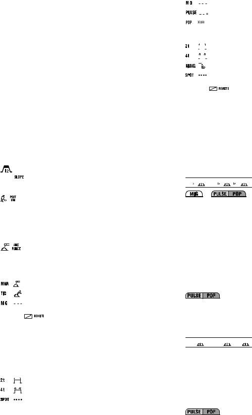
2- Connettore 14p per il collegamento del comando a distanza. 3- Raccordi rapidi per tubazioni acqua della torcia MIG.
4- Attacco centralizzato per torcia MIG (Euro). sul lato posteriore:
5- Connettore 14p per cavo comando di collegamento con la saldatrice.
6- Presa rapida positiva (+) per cavo corrente di saldatura di collegamento con la saldatrice.
7- Attacco tubo gas (bombola) per saldatura MIG.
8- Raccordi rapidi per collegamento tubi mandata e ritorno acqua di raffreddamento.
9- Fusibile.
4.2 PANNELLO DI CONTROLLO DELLA SALDATRICE (FIG. C)
Il pannello di controllo è abilitato (cioè i comandi e le segnalazioni sono attivi) solo se la saldatrice non è collegata all’alimentatore di filo, oppure è impostato il processo MMA o TIG. Qualora la saldatrice sia collegata all’alimentatore di filo, oppure la funzione impostata è MIG, quest’ultimo assume automaticamente il controllo completo e sul display (3) della saldatrice sarà visualizzata la scritta “feed”.
1- LED di segnalazione Allarme (l’output della saldatrice è bloccato). Sul display
(3) appare un messaggio d’allarme.
Il ripristino della saldatrice è automatico alla cessazione della causa d’allarme.
2- LED presenza tensione in uscita (output attivo). 3- Display alfanumerico a 3 digit. Indica:
-La corrente di saldatura in ampere.
Il valore indicato è quello impostato, con saldatrice a vuoto, mentre è quello reale durante il funzionamento.
-Un messaggio di allarme con la seguente codifica:
-”AL1” : intervento protezione termica del circuito primario.
-”AL2” : intervento protezione termica del circuito secondario.
-”AL3” : intervento protezione per sovratensione della linea di alimentazione.
-”AL4” : intervento protezione per sottotensione della linea di alimentazione.
-”AL5” : modello con GRA: intervento protezione per pressione insufficiente del circuito raffreddamento ad acqua della torcia. Ripristino non automatico.
modello senza GRA: mancanza collegamento connettore di polarizzazione alla macchina (FIG. E).
-“AL9” : intervento protezione componenti magnetici.
-“AL10” : guasto linea seriale: seriale sconnessa.
-“AL11” : intervento protezione per mancanza fase della linea di
alimentazione.
-“AL12” : guasto linea seriale: errore nei dati.
-“AL13” : eccessivo deposito di polvere interno alla saldatrice, ripristino con:
-pulizia interna della macchina;
-tasto selezione parametri del pannello di controllo.
Allo spegnimento della saldatrice può verificarsi, per alcuni secondi, la segnalazione ”AL11” e “OFF”.
3a, 3b, 3c - LED di indicazione unità di misura in corso (ampere, secondi, percentuale).
4- Manopola di comando encoder.
Permette la regolazione dei parametri di saldatura (4a).
: Corrente di saldatura in modalità TIG/MMA.


 : In modalità tig permette la riduzione graduale della corrente al rilascio del pulsante torcia (regolazione 0-3secondi) e LED (3b) illuminato.
: In modalità tig assume il significato di “Post-gas”, permettendo di adeguare il tempo di efflusso del gas di protezione a partire dall’arresto della saldatura (regolazione 0,1-10 secondi e LED (3b) illuminato).


 : E’reso attivo esclusivamente se è selezionata la modalità “SPOT” col tasto (7). Permette l’esecuzione di puntature in modalità TIG con controllo della durata della saldatura (regolazione 0,1-10 secondi e LED (3b) illuminato).
: |
In funzionamento ad elettrodo MMA, il parametro assume |
|
il significato di “Arc force” permettendo l’impostazione della |
|
sovracorrente dinamica (regolazione 0-100% e LED (3c) |
|
illuminato). |
5- Tasto di selezione del procedimento di saldatura. |
|
Premendo il tasto si illumina il led in corrispondenza alla modalità di saldatura |
|
che si intende adottare: |
|
: |
elettrodo rivestito “MMA”. |
: TIG-DC con innesco dell’arco a contatto (LIFT-ARC).
|
|
|
: |
MIG. |
|
|
|
||
|
||||
6- Tasto di inserzione del comando a distanza. |
||||
Con LED |
illuminato, la regolazione può essere esclusivamente |
|||
effettuata dal comando a distanza e precisamente:
a)Comando a un potenziometro: permette la regolazione della corrente di saldatura in modalità TIG/MMA.
b)Comando a due potenziometri: permette la regolazione della corrente di saldatura TIG/MMA e la regolazione della SLOPE DOWN in TIG o ARC FORCE in MMA (selezione LED parametro automatica).
c)Comando a pedale: permette la regolazione della corrente di saldatura in
modalità TIG/MMA.
NOTA: La selezione “A DISTANZA“ (remote) è resa possibile solo se un comando a distanza è effettivamente collegato al suo connettore.
7- Tasto di selezione della modalità di controllo del pulsante torcia TIG.
Premendo il tasto si illumina il LED in corrispondenza del:
: funzionamento a 2 tempi, ON-OFF con pulsante premuto.
: funzionamento a 4 tempi, ON-OFF con pulsante rilasciato.
: funzionamento in puntatura TIG (SPOT).
4.2.1 PANNELLO DI CONTROLLO DELL’ALIMENTATORE DI FILO (FIG. D) 1- LED di segnalazione ALLARME (l’output della macchina è bloccato).
Il ripristino è automatico alla cessazione della causa d’allarme. Messaggi di allarme esclusivi indicati sui displays (15) e (16):
-“AL7” : intervento protezione per sovracorrente in saldatura MIG-MAG.
-“AL8” : guasto linea seriale: corto in torcia.
Per i rimanenti vedi “PANNELLO DI CONTROLLO DELLA SALDATRICE” (par.
2- |
4.2). |
|
|
|
|
|
|
|
|
|
|
|
LED di segnalazione PRESENZA TENSIONE IN TORCIA O SU |
||||||||||||
3- |
ELETTRODO. |
|
||||||||||
LED di segnalazione PROGRAMMAZIONE SALDATRICE. |
personalizzati |
|||||||||||
4 - |
Tasto di richiamo (RECALL) dei programmi di saldatura |
|||||||||||
5- |
(vedi par. 4.3.2.4). |
personalizzati |
||||||||||
Tasto di memorizzazione (SAVE) di programmi di saldatura |
||||||||||||
6- |
(vedi par. 4.3.2.3). |
|
||||||||||
Tasto di selezione programma di saldatura e display a 2 digit. |
||||||||||||
|
Premendo in successione il tasto, il display visualizza i numeri compresi tra “0” |
|||||||||||
|
e “36”. Ad ogni numero fra “1” e “36” è associato un programma di saldatura |
|||||||||||
|
sinergico (vedi TAB. 3) mentre al numero “0” è associata la funzionalità in |
|||||||||||
|
manuale della saldatrice, in cui tutti i parametri possono essere impostati |
|||||||||||
7- |
dall’operatore (solo in MIG-MAG short e spray arc). |
|
||||||||||
Tasto di selezione del procedimento di saldatura. |
|
|||||||||||
|
Premendo il tasto si illumina il LED in corrispondenza alla modalità di saldatura |
|||||||||||
|
che si intende adottare: |
|
||||||||||
|
|
|
|
|
|
|
|
|
|
|
:MIG-MAG con modalità “SHORT/SPRAY ARC”. |
|
|
|
|
|
|
|
|
|
|
|
|
||
|
|
|
|
|
|
|
|
|
|
|
:MIG-MAG con modalità “PULSE ARC”. |
|
|
|
|
|
|
|
|
|
|
|
|
|
|
|
|
|
|
|
|
|
|
|
|
|
:MIG-MAG con modalità “PULSE ON PULSE”. |
|
|
|
|
|
|
|
|
|
|
|
|
|
|
8- |
Tasto di selezione della modalità di controllo del pulsante torcia MIG- |
|||||||||||
|
MAG. |
|
|
|
||||||||
|
Premendo il tasto si illumina il LED in corrispondenza del: |
|
||||||||||
|
|
|
|
|
|
|
|
|
|
|
:funzionamento a 2 tempi, ON-OFF con pulsante premuto. |
|
|
|
|
|
|
|
|
|
|
|
|
||
|
|
|
|
|
|
|
|
|
|
|
:funzionamento a 4 tempi, ON-OFF con pulsante rilasciato. |
|
|
|
|
|
|
|
|
|
|
|
|
||
|
|
|
|
|
|
|
|
|
|
|
:funzionamento bi-level per MIG-MAG, TIG. |
|
|
|
|
|
|
|
|
|
|
|
|
:funzionamento in puntatura MIG-MAG (SPOT). |
|
9- |
Tasto di inserzione del comando a distanza. |
esclusivamente |
||||||||||
|
Con LED |
|
illuminato, la regolazione può essere |
|||||||||
effettuata dal comando a distanza e precisamente:
-comando a due potenziometri: sostituisce la funzione delle manopole encoder (14) e (13).
NOTA: La selezione “A DISTANZA“ (remote) è resa possibile solo se un comando a distanza è effettivamente collegato al suo connettore.
10Tasto di selezione dei parametri di saldatura.
Premendo in successione il tasto, viene illuminato uno dei LEDS da (10a) a (10h) a cui è associato uno specifico parametro. L’impostazione del valore di ciascun parametro attivato, è eseguibile per mezzo della manopola (13) ed indicato sul display (15). Durante queste impostazioni la manopola (14) regola il valore del livello principale di saldatura indicato sul display (16), sia esso corrente o velocità filo (vedi descrizione punto (14)), tranne che per (10b).
Solo con il led (10b) acceso la manopola (14) permette di regolare il valore del livello secondario (vedi descrizione led (10b)).
Nota: i parametri che non sono modificabili dall’operatore, a seconda che si stia lavorando con un programma sinergico o in modalità manuale “PRG 0” sono automaticamente esclusi dalla selezione; il LED corrispondente non s’illumina.
10a- 


Questo parametro è visualizzato automaticamente durante le operazioni di saldatura MIG-MAG, indicando la tensione d’arco reale (led (15a) illuminato). Regolazioni:
 Short arc
Durante l’impostazione di un programma sinergico MIG-MAG Short arc permette di regolare la correzione che si intende apportare alla lunghezza d’arco calcolata in sinergia (range da -5% a +5%) (led (15c) illuminato).
Nella stessa condizione impostando la funzione bi-level il parametro assume il significato di correzione della lunghezza d’arco del livello principale di saldatura, calcolata sempre in sinergia (range da -5% a +5%) (led (15c) illuminato).
 Short arc “PRG 0”
Sempre in funzionamento MIG-MAG Short arc, programma manuale “PRG 0”, permette di impostare la tensione d’arco effettiva (range 10-40)(led (15a) illuminato).
Nella stessa condizione, impostando la funzione bi-level il parametro assume il significato di tensione d’arco effettiva del livello principale di saldatura (range 10-40) (led (15a) illuminato).
Durante l’impostazione di un programma sinergico MIG-MAG Pulse arc permette di regolare la correzione che si intende apportare alla lunghezza d’arco calcolata in sinergia (range da -5% a +5%) (led (15c) illuminato).
Nella stessa condizione impostando la funzione bi-level, pulse on pulse o Tstart il parametro assume il significato di correzione della lunghezza d’arco del livello principale di saldatura, calcolata sempre in sinergia (range da -5% a +5%) (led (15c) illuminato).
10b- 


 Short arc
Nei programmi sinergici MIG-MAG short arc, impostando la funzione bi-level permette di regolare la corrente/velocità filo (con manopola (14)) e la correzione della lunghezza d’arco (con manopola (13)) del livello secondario di saldatura, calcolata in sinergia (range da -5% a +5%) (led (15c) illuminato).
 Short arc “PRG 0”
Selezionando il programma manuale “PRG 0” con la funzione bi-level, permette di regolare la velocità del filo (con manopola (14), (led 16c) illuminato) e la tensione d’arco effettiva (con manopola (13)) del livello secondario I1 di saldatura (range 10-40)((led (15a) illuminato).
In modalità MIG-MAG pulse arc, impostando le funzioni bi-level, pulse on pulse o Tstart, permette di regolare la corrente I1 e Is (Istart)(con manopola (14)) e la correzione della lunghezza d’arco (con manopola (13)) del livello secondario di saldatura, calcolata in sinergia (range da -5% a +5%)(led (15c) illuminato).
- 14 -

10c- 


 Short arc “PRG 0”
In modalità manuale “PRG 0” permette di adeguare la velocità del filo alla partenza della saldatura per ottimizzare l’innesco dell’arco (regolazione 1-100% e LED (15c) illuminato).
In modalita MIG-MAG Pulse arc 2 TEMPI permette di regolare la durata della corrente iniziale (Tstart). Impostando a zero il parametro, viene disattivata la funzione, mentre impostando un qualsiasi valore maggiore di zero (regolazione 0,1-3 secondi) è possibile selezionare il LED (10b) per regolare la correzione della tensione d’arco e il valore della corrente iniziale (livello secondario). La corrente iniziale può essere impostata più alta o più bassa di quella principale di saldatura; una corrente iniziale più alta è molto utile soprattutto per la saldatura dell’alluminio e delle sue leghe, questo infatti permette di scaldare più velocemente il pezzo (“Hot-start”).
In modalità MIG-MAG Pulse on pulse permette di regolare la durata della corrente principale di saldatura (regolazione 0,1-10 secondi e LED (15b) illumanato).
10d- 

 Short arc “PRG 0”
In modalità manuale MIG-MAG “PRG 0” permette di regolare la reattanza elettronica (regolazione 20-80% e LED (15c) illuminato). Un valore più alto determina un bagno di saldatura più caldo. In modalità bi-level la reattanza elettronica è comune per entrambi i livelli impostati.
In modalità MIG-MAG pulse arc il parametro determina la strozzatura dell’arco. Più alto è il valore e più concentrato sarà l’arco durante la saldatura. In una modalità di saldatura che utilizza due livelli di corrente (bi-level, pulse on pulse o Tstart) la strozzatura d’arco è comune per entrambi i livelli impostati (+1% / -1%).
In modalità MIG-MAG Pulse on pulse permette di regolare la durata della corrente secondaria di saldatura (regolazione 0,1-10 secondi e LED (15b) illuminato).
10e-
Bruciatura filo all’arresto della saldatura (Burn-back).
Permette di regolare il tempo di bruciatura del filo all’arresto della saldatura.
Durante l’impostazione di un programma sinergico MIG-MAG, permette di regolare la correzione che si intende apportare al BURN_BUCK TIME calcolato in sinergia (range -1% / +1% LED (15c) illuminato).
 Short arc “PRG 0”
Con opportuna impostazione permette di evitare l’incollaggio del filo al pezzo (regolazione 0,001-1 secondi e led (15b) illuminato).
10f-
Post-gas
Permette di adeguare il tempo di efflusso del gas di protezione a partire dall’arresto della saldatura (regolazione 0,1-10 secondi e LED (15b) illuminato).
10g-
Rampa discesa corrente di saldatura (SLOPE DOWN).
E’ reso attivo esclusivamente utilizzando programmi sinergici MIG-MAG Short arc, Pulse arc e Pulse on Pulse.
Permette la riduzione graduale della corrente al rilascio del pulsante torcia (regolazione 0-3 secondi e LED (15b) illuminato).
10h-
Tempo di puntatura (SPOT TIME).
E’ reso attivo esclusivamente se è selezionata la modalità “SPOT” col tasto (8). Permette l’esecuzione di puntature MIG-MAG con controllo della durata della saldatura (regolazione 0,1-10 secondi e LED (15b) illuminato).
11Tasto di attivazione manuale dell’elettrovalvola gas.
Il tasto permette l’efflusso gas (spurgo tubazioni - regolazione portata) senza la necessità di agire sul pulsante della torcia; il tasto è ad azione momentanea.
12Tasto avanzamento manuale del filo.
Il tasto permette di fare avanzare il filo nella guaina della torcia senza la necessità di agire sul pulsante torcia; è ad azione momentanea e la velocità di avanzamento è fissa.
13Manopola encoder per la regolazione dei parametri di saldatura (vedi 10a-10h).
14Manopola encoder.
La manopola regola:
-La corrente di saldatura I2 (led (16a) illuminato).
-La velocità di avanzamento del filo (led (16c) illuminato).
-Lo spessore del pezzo usato in saldatura (led (16b) illuminato).
In una modalità di saldatura che utilizza due livelli di corrente (bi-level, pulse on pulse o Tstart) con il led (10b) acceso la manopola regola:
- La corrente di saldatura I1 (led (16a) illuminato) del livello secondario.
- La velocità di avanzamento del filo del livello secondario di saldatura (led (16c) illuminato).
- Lo spessore del pezzo usato in saldatura (led (16b) illuminato) riferito al livello secondario.
15Display alfanumerico a 3 digit. Indica:
-il valore dei parametri di saldatura (vedi da (10a) a (10h)) con funzionamento a vuoto.
-la tensione reale d’arco, in saldatura.
NOTA: all’arresto della saldatura, il display commuta automaticamente al valore di impostazione.
- una segnalazione d’allarme (vedi punto 1).
15a, 15b, 15cLED di indicazione unità di misura in corso (volt, secondi, percentuale).
16Display alfanumerico 3 digit. Indica:
-il valore impostato con la manopola encoder (14).
-la corrente reale, in saldatura.
NOTA: all’arresto della saldatura, il display commuta automaticamente al valore di impostazione.
- una segnalazione d’allarme (vedi punto 1).
16a, 16b, 16cLED di indicazione unità di misura in corso (corrente ampere (A), spessore in millimetri (mm) e velocità filo metri/minuto (m/min)).
17Tasto di selezione unità di misura Ampere/Spessore in m/min (LED (16a) (16b) (16c)).
Nei programmi sinergici MIG/MAG permette di impostare mediante l’encoder (14) rispettivamente lo spessore del materiale da saldare, la corrente di saldatura, la velocità del filo.
L’impostazione di ogni singolo parametro (es. spessore del materiale) definisce automaticamente gli altri parametri (es. corrente di saldatura e velocità del filo). In “PRG 0” selezione manuale: è possibile solo la regolazione della velocità del filo (led (16c) illuminato).
4.3 RICHIAMO E MEMORIZZAZIONE DEI PROGRAMMI
4.3.1 RICHIAMO PROGRAMMI PREMEMORIZZATI DAL COSTRUTTORE 4.3.1.1 Programmi MIG-MAG SINERGICI
La saldatrice prevede 36 programmi sinergici memorizzati, con caratteristiche identificate in tabella (TAB. 3) a cui è necessario fare riferimento per la selezione di un programma adatto al tipo di saldatura che si intende eseguire.
La selezione di un determinato programma si effettua premendo in successione il tasto “PRG” a cui corrisponde su display un numero compreso tra “0” e “36” (al numero “0” non corrisponde un programma sinergico ma il funzionamento in modalità manuale, come descritto nel paragrafo successivo).
Nota: All’interno di un programma sinergico è prioritario eseguire la scelta della modalità di trasferimento desiderata, PULSE ARC oppure SHORT/SPRAY ARC, tramite l’apposito tasto (vedi FIG. D, tasto (7)).
Nota: Tutte le tipologie di filo non previste in tabella possono essere utilizzate in modalità manuale “PRG 0”.
4.3.1.2 FUNZIONAMENTO IN MODALITÀ MANUALE “PRG 0”
Il funzionamento in manuale corrisponde alla cifra “0” sul display ed è attivo solo se precedentemente è stato selezionato la modalità di trasferimento SHORT/SPRAY ARC (FIG. D, tasto (7)).
In questa modalità, non essendo prevista alcuna sinergia, tutti i parametri di saldatura devono essere impostati manualmente dall’operatore.
Attenzione! L’impostazione di tutti i parametri è libera quindi i valori ad essi attribuiti potrebbero risultare incompatibili con un corretto procedimento di saldatura.
Nota: NON è possibile utilizzare la modalità di trasferimento PULSE ARC in selezione manuale.
4.3.2 MEMORIZZAZIONE E RICHIAMO PROGRAMMI PERSONALIZZATI IN MIGMAG
4.3.2.1 Introduzione
La saldatrice permette di memorizzare (SAVE) programmi di lavoro personalizzati relativi ad un set di parametri validi per una determinata saldatura. Ogni programma memorizzato può essere richiamato (RECALL) in qualunque momento mettendo così a disposizione dell’utilizzatore la saldatrice “pronta all’uso“ per un specifico lavoro ottimizzato in precedenza.
4.3.2.2Capacità di memorizzazione di programmi personalizzati in MIG-MAG
La saldatrice prevede la memorizzazione di 40 programmi personalizzati riferiti alle tre modalità di trasferimento in sinergia (SHORT/SPRAYARC Pulse arc e Pulse on pulse) e al funzionamento in modalità manuale, con le seguenti specifiche:
- SHORT/SPRAY ARC SINERGICO: 10 programmi memorizzabili (numeri disponibili da “1” a “10”);
- SHORT/SPRAY ARC MANUALE (“PRG=0”): 10 programmi memorizzabili (numeri disponibili da “1” a “10”);
- PULSE ARC SINERGICO: 10 programmi memorizzabili (numeri disponibili da “1” a “10”);
- PULSEARC SINERGICO PULSE ON PULSE: 10 programmi memorizzabili (numeri disponibili da “1” a “10”).
Nota: Per richiamare il programma che si intende utilizzare:
a) eseguire la scelta della modalità di trasferimento desiderata PULSE ARC, PULSE ARC PULSE-ON- PULSE o SHORT/SPRAY ARC oppure selezionare “PRG=0” se programmi prememorizzati in modalità manuale;
b) selezionare il numero del programma (come descritto nel par.4.3.1).
4.3.2.3Procedura di memorizzazione (SAVE).
Dopo avere regolato la saldatrice in modo ottimale per una determinata saldatura, procedere come segue (vedi FIG. D):
a)Premere il tasto (5) “SAVE”.
b)Appare “Pr” sul display (16) ed un numero (compreso tra “1” e “10”) sul display
(15).
c)Ruotando la manopola encoder (indifferentemente la (13) o la (14)), scegliere il numero con cui si desidera memorizzare il programma ( vedi anche 4.3.2 ).
d)Premere nuovamente il tasto “SAVE”.
e)I display (15) e (16) lampeggiano.
f)Ripremere, entro il tempo di due secondi, il tasto “SAVE”.
g)Sui display appare “St Pr”, quindi il programma è stato memorizzato; dopo 2 secondi i display commutano automaticamente su valori relativi ai parametri appena
salvati.
Nota. Se, a display lampeggianti, non viene ripremuto il tasto “SAVE” entro 2 secondi, i display indicano “No St” ed il programma non viene memorizzato; i display ritornano automaticamente all’indicazione iniziale.
4.3.2.4 Procedura di richiamo di un programma personalizzato (RECALL)
Prima di eseguire le operazioni di richiamo di un programma, verificare che la modalità di trasferimento selezionata (PULSEARC, PULSEARC PULSE-ON-PULSE, SHORT/ SPRYARC o “PRG=0”) sia effettivamente quella con cui si intende operare. Procedere quindi come segue (vedi FIG. D):
a)Premere il tasto “RECALL”.
b)Appare “Pr” sul display (16) ed un numero (compreso tra “1” e “10”) sul display
(15).
c)Ruotando la manopola encoder (indifferentemente la (13) o la (14)) scegliere il numero col quale si era memorizzato il programma che ora si intende utilizzare.
d)Ripremere il tasto “RECALL” per un tempo maggiore di 2 secondi.
e)Sui display appare “Ld Pr” quindi il programma è stato richiamato; i display commutano automaticamente, dopo 2 secondi, sui valori relativi al programma appena richiamato.
Nota: Se il tasto “RECALL” non viene ripremuto per un tempo superiore a 2 secondi, i display indicano “No Ld” ed il programma non viene caricato; i display ritornano automaticamente all’indicazione iniziale.
- 15 -
NOTE:
-DURANTE LE OPERAZIONI CON IL TASTO “SAVE” E “RECALL” E’ ILLUMINATO IL LED “PRG”.
-UN PROGRAMMA RICHIAMATO PUO’ ESSERE MODIFICATO A PIACIMENTO DALL’OPERATORE, MA I VALORI MODIFICATI NON VENGONO SALVATI AUTOMATICAMENTE. SE SI DESIDERANO MEMORIZZARE I NUOVI VALORI SULLO STESSO PROGRAMMA E’ NECESSARIO ESEGUIRE LA PROCEDURA DI MEMORIZZAZIONE (vedi 4.3.2.3).
-LA REGISTRAZIONE DEI PROGRAMMI PERSONALIZZATI E LA RELATIVA SCHEDULAZIONE DEI PARAMETRI ASSOCIATI E’ A CURA DELL’UTILIZZATORE.
-NON POSSONO ESSERE SALVATI PROGRAMMI PERSONALIZZATI IN MODALITÀ ELETTRODO MMA O TIG.
5. INSTALLAZIONE
ATTENZIONE! ESEGUIRE TUTTE LE OPERAZIONI DI INSTALLAZIONE ED ALLACCIAMENTI ELETTRICI CON LA SALDATRICE RIGOROSAMENTE SPENTA E SCOLLEGATA DALLA RETE DI
ALIMENTAZIONE.
GLI ALLACCIAMENTI ELETTRICI DEVONO ESSERE ESEGUITI ESCLUSIVAMENTE DA PERSONALE ESPERTO O QUALIFICATO.
5.1 ALLESTIMENTO
-Disimballare il carrello ed eseguirne il montaggio in accordo alle istruzioni in dotazione.
-Disimballarelasaldatrice,l’alimentatoredifilo,el’eventualegruppodiraffreddamento;
eseguirne l’installazione sul carrello.
nota: inserire connettore di polarizzazione se non viene collegato il GRA (FIG. E).
5.2 MODALITÀDISOLLEVAMENTODELLASALDATRICEODELL’ATTREZZATURA DI SALDATURA
-La saldatrice deve essere sollevata come in figura (FIG. O), priva di parti asportabili (torcia, tubi gas, cavi, ecc) che potrebbero staccarsi.
Come disposto in figura, eseguire il montaggio degli anelli di fissaggio utilizzando le due viti M8x25 disposte in accessorio.
Attenzione: gli anelli di sollevamento ad occhiello con foro filettato M8 non sono compresi nella fornitura.
-L'attrezzatura di saldatura deve essere sollevata come in figura (FIG. P), priva di parti asportabili (alimentatore di filo, bombola, cavi, comando a distanza) che potrebbero staccarsi.
Attenzione:utilizzarecontemporaneamentei4puntidisollevamentoappositamente predisposti.
5.3 UBICAZIONE DELLA SALDATRICE
Individuare il luogo d’installazione della saldatrice in modo che non vi siano ostacoli in corrispondenza della apertura d’ingresso e d’uscita dell’aria di raffreddamento; accertarsi nel contempo che non vengano aspirate polveri conduttive, vapori corrosivi, umidità, etc..
Mantenere almeno 250mm di spazio libero attorno alla saldatrice.
ATTENZIONE! Posizionare la saldatrice su di una superficie piana di portata adeguata al peso per evitarne il ribaltamento o spostamenti pericolosi.
5.4COLLEGAMENTO ALLA RETE
5.4.1Avvertenze
-Prima di effettuare qualsiasi collegamento elettrico, verificare che i dati di targa della saldatrice corrispondano alla tensione e frequenza di rete disponibili nel luogo d’installazione.
-La saldatrice deve essere collegata esclusivamente ad un sistema di alimentazione con conduttore di neutro collegato a terra.
-Per garantire la protezione contro il contatto indiretto usare interuttori differenziali del tipo:
-Tipo A ( ) per macchine monofasi;
-Tipo B ( 


 ) per macchine trifasi.
-Al fine di soddisfare i requisiti della Norma EN 61000-3-11 (Flicker) si consiglia il collegamento della saldatrice ai punti di interfaccia della rete di alimentazione che presentano un’impedenza minore di Zmax =0.283 ohm.
-La saldatrice non rientra nei requisiti della norma IEC/EN 61000-3-12.
Se essa viene collegata a una rete di alimentazione pubblica, è responsabilità dell’installatore o dell’utilizzatore verificare che la saldatrice possa essere connessa (se necessario, consultare il gestore della rete di distribuzione).
5.4.2 Spina e presa
Collegare al cavo di alimentazione una spina normalizzata, (3P + T) di portata adeguata e predisporre una presa di rete dotata di fusibili o interruttore automatico; l’apposito terminale di terra deve essere collegato al conduttore di terra (giallo-verde) della linea di alimentazione.
La tabella (TAB. 1) riporta i valori consigliati in ampere dei fusibili ritardati di linea scelti in base alla massima corrente nominale erogata dalla saldatrice e alla tensione nominale di alimentazione.
5.5 CONNESSIONI CIRCUITO DI SALDATURA
ATTENZIONE! PRIMA DI ESEGUIRE I SEGUENTI COLLEGAMENTI ACCERTARSI CHE LA SALDATRICE SIA SPENTA E SCOLLEGATA DALLA RETE DI ALIMENTAZIONE.
La tabella (TAB. 1) riporta il valore consigliato per i cavi di saldatura (in mm2)
5.5.1 SALDATURA A FILO MIG-MAG (FIG.F) 5.5.1.1 Collegamento della bombola gas
-Avvitare il riduttore di pressione alla valvola della bombola gas interponendo la riduzione apposita fornita come accessorio, quando venga utilizzato gas Argon o miscela Ar/CO2.
-Collegare il tubo di entrata del gas al riduttore e serrare la fascetta in dotazione; collegare quindi l’altra estremità del tubo all’apposito raccordo sul retro della saldatrice e serrare con la fascetta in dotazione.
-Allentare la ghiera di regolazione del riduttore di pressione prima di aprire la valvola della bombola.
5.5.1.2 Collegamento della Torcia
-Innestare la torcia nel connettore ad essa dedicato serrando a fondo manualmente la ghiera di bloccaggio.
-Predisporla al primo caricamento del filo, smontando l’ugello ed il tubetto di contatto, per facilitarne la fuoriuscita.
-Cavo corrente di saldatura alla presa rapida (+).
-cavo comando all’apposito connettore.
-tubazioni acqua per versioni R.A. (torcia raffreddata ad acqua) a raccordi rapidi.
-Porre attenzione che i connettori siano ben serrati onde evitare surriscaldamenti e perdite di efficienza.
-Collegare il tubo di entrata del gas al riduttore e serrare la fascetta in dotazione; collegare quindi l’altra estremità del tubo all’apposito raccordo sul retro della saldatrice e serrare con la fascetta in dotazione.
5.5.1.3 Collegamento del cavo di ritorno della corrente di saldatura
-Collegare il cavo al pezzo da saldare o al banco metallico su cui quest’ultimo è appoggiato, il più vicino possibile al giunto in esecuzione.
-Il cavo va collegato alla presa rapida con il simbolo (-).
5.5.2 SALDATURA TIG (FIG. G)
5.5.2.1 Collegamento della bombola gas
-Avvitare il riduttore di pressione alla valvola della bombola gas interponendo la riduzione apposita fornita come accessorio, per gas Argon.
-Collegare il tubo di entrata del gas al riduttore e serrare la fascetta in dotazione; collegare quindi l’altra estremità del tubo all’apposito raccordo sul retro della saldatrice e serrare con la fascetta in dotazione.
-Allentare la ghiera di regolazione del riduttore di pressione prima di aprire la valvola della bombola.
5.5.2.2 Collegamento del cavo di ritorno della corrente di saldatura
-Collegare il cavo al pezzo da saldare o al banco metallico su cui quest’ultimo è appoggiato, il più vicino possibile al giunto in esecuzione.
-Collegare il cavo sulla saldatrice alla presa rapida (+).
5.5.2.3 Collegamento della torcia
Collegare la torcia TIG alla presa rapida (-) sul pannello anteriore della saldatrice; completare il collegamento del tubo gas e del cavo comando torcia.
5.5.3 SALDATURA CON ELETTRODO RIVESTITO MMA (FIG. H) 5.5.3.1 Collegamento della pinza portaelettrodo
La quasi totalità degli elettrodi rivestiti va collegata al polo positivo (+) del generatore; eccezionalmente al polo negativo (-) per elettrodi con rivestimento acido.
Collegare il cavo della pinza portaelettrodo alla presa rapida (+) sul pannello anteriore.
Nota: in alcuni casi è consigliata la polarità (-) alla pinza portaelettrodo; controllare quindi le indicazioni del fabbricante degli elettrodi.
5.5.3.2 Collegamento del cavo di ritorno della corrente di saldatura con pinza di massa
-Collegare la pinza di massa al pezzo da saldare o al banco metallico su cui quest’ultimo è appoggiato, il più vicino possibile al giunto in esecuzione.
-Collegare il cavo sulla saldatrice alla presa rapida (-).
5.5.4 RACCOMANDAZIONI
-Ruotare a fondo i connettori dei cavi di saldatura nelle prese rapide, per garantire un perfetto contatto elettrico; in caso contrario si produrranno surriscaldamenti dei connettori stessi con relativo loro rapido deterioramento e perdita di efficienza.
-Utilizzare i cavi di saldatura più corti possibile.
-Evitare di utilizzare strutture metalliche non facenti parte del pezzo in lavorazione, in sostituzione del cavo di ritorno della corrente di saldatura; ciò può essere pericoloso per la sicurezza e dare risultati insoddisfacenti per la saldatura.
5.6CARICAMENTO BOBINA FILO (FIG. I)
ATTENZIONE! PRIMA DI INIZIARE LE OPERAZIONI DI CARICO DEL FILO, ACCERTARSI CHE LA SALDATRICE SIA SPENTA E SCOLLEGATA DALLA RETE DI ALIMENTAZIONE.
VERIFICARE CHE I RULLI TRAINAFILO, LA GUAINA GUIDAFILO ED IL TUBETTO DI CONTATTO DELLA TORCIA SIANO CORRISPONDENTI AL DIAMETRO E ALLA NATURADELFILO CHE S’INTENDE UTILIZZARE E CHE SIANO CORRETTAMENTE MONTATI. DURANTE LE FASI DI INFILAMENTO DEL FILO NON INDOSSARE GUANTI DI PROTEZIONE.
-Aprire lo sportello del vano aspo.
-Posizionare la bobina di filo sull’aspo; assicurarsi che il piolino di trascinamento dell’aspo sia correttamente alloggiato nel foro previsto (1a).
-Liberare i/il controrulli/o di pressione e allontanarli/o dai/l rulli/o inferiori/e (2a).
-Verificare che i/il rullini/o di traino siano/sia adatti/o al filo utilizzato (2b).
-Liberare il capo del filo, troncarne l’estremità deformata con un taglio netto e privo di bava; ruotare la bobina in senso antiorario ed imboccare il capo del filo nel guidafilo d’entrata spingendolo per 50-100mm nel guidafilo del raccordo torcia (2c).
-Riposizionare i/il controrulli/o regolandone la pressione ad un valore intermedio, verificare che il filo sia correttamente posizionato nella cava del rullo inferiore (3).
-Frenare leggermente l’aspo agendo sull’apposita vite di regolazione posizionata al centro dell’aspo stesso (1b).
-Togliere l’ugello e il tubetto di contatto (4a).
-Inserire la spina della saldatrice nella presa di alimentazione, accendere la saldatrice, premere il pulsante torcia o pulsante di avanzamento filo sul pannello comandi (se presente) e attendere che il capo del filo percorrendo tutta la guaina guidafilo fuoriesca per 10-15cm dalla parte anteriore della torcia, rilasciare il pulsante.
ATTENZIONE! Durante queste operazioni il filo è sotto tensione elettrica ed è sottoposto a forza meccanica; può quindi causare, non adottando opportune precauzioni, pericoli di shock elettrico, ferite ed
innescare archi elettrici:
-Non indirizzare l’imboccatura della torcia contro parti del corpo.
-Non avvicinare alla bombola la torcia.
-Rimontare sulla torcia il tubetto di contatto e l’ugello (4b).
-Verificare che l’avanzamento del filo sia regolare; tarare la pressione dei rulli e la frenatura dell’aspo ai valori minimi possibili verificando che il filo non slitti nella cava e che all’atto dell’arresto del traino non si allentino le spire di filo per eccessiva inerzia della bobina.
-Troncare l’estremità del filo fuoriuscente dall’ugello a 10-15mm.
-Chiudere lo sportello del vano aspo.
5.7 SOSTITUZIONE DELLA GUAINA GUIDAFILO NELLA TORCIA (FIG. L)
Prima di procedere alla sostituzione della guaina, stendere il cavo della torcia evitando che formi delle curve.
5.7.1 Guaina a spirale per fili acciaio
1- Svitare l’ugello ed il tubetto di contatto della testa della torcia.
2- Svitare il dado fermaguaina del connettore centrale e sfilare la guaina esistente. 3- Infilare la nuova guaina nel condotto del cavo-torcia e spingerla dolcemente fino
- 16 -
a farla fuoriuscire dalla testa della torcia. 4- Riavvitare il dado fermaguaina a mano.
5- Tagliare a filo il tratto di guaina eccedente comprimendola leggermente; ritoglierla dal cavo torcia.
6- Smussare la zona di taglio della guaina e reinserirla nel condotto del cavo-torcia. 7- Riavvitare quindi il dado stringendolo con una chiave.
8- Rimontare il tubetto di contatto e l’ugello.
5.7.2 Guaina in materiale sintetico per fili alluminio
Eseguire le operazioni 1, 2, 3 come indicato per la guaina acciaio (non considerare le operazioni 4, 5, 6, 7,8).
9- Riavvitare il tubetto di contatto per alluminio verificando che vada in contatto con la guaina.
10Inserire sull’estremità opposta della guaina (lato attacco torcia) il nipple di ottone, l’anello OR e, mantenendo la guaina in leggera pressione, serrare il dado fermaguaina. La parte della guaina in eccesso sarà rimossa a misura successivamente (vedi (13)). Estrarre dal raccordo torcia del trainafilo il tubo capillare per guaine acciaio.
11NON E’ PREVISTO IL TUBO CAPILLARE per guaine alluminio di diametro 1,6- 2,4mm (colore giallo); la guaina verrà quindi inserita nel raccordo torcia senza di esso.
Tagliare il tubo capillare per guaine alluminio di diametro 1-1,2mm (colore rosso) ad una misura inferiore di 2 mm circa rispetto a quella del tubo acciaio, ed inserirlo sull’estremità libera della guaina.
12Inserire e bloccare la torcia nel raccordo del trainafilo, segnare la guaina a 1-2mm di distanza dai rulli, riestrarre la torcia.
13Tagliare la guaina, alla misura prevista, senza deformarne il foro d’ingresso. Rimontare la torcia nel raccordo del trainafilo e montare l’ugello gas.
6.SALDATURA: DESCRIZIONE DEL PROCEDIMENTO
6.1SALDATURA MIG-MAG
6.1.1 MODALITÀ DI TRASFERIMENTO SHORT ARC (ARCO CORTO)
La fusione del filo e distacco della goccia avviene per corto-circuiti successivi dalla punta del filo nel bagno di fusione (fino a 200 volte al secondo).
Acciai al carbonio e basso-legati |
0,6-1,2mm |
|
- |
Diametro fili utilizzabili: |
|
- Gamma corrente di saldatura: |
40-210A |
|
- |
Gamma tensione d’arco: |
14-23V |
- |
Gas utilizzabile: |
CO2 o miscele Ar/CO2 o Ar/CO2 -O2 |
Acciai inossidabili |
0,8-1mm |
|
- |
Diametro fili utilizzabili: |
|
- Gamma corrente di saldatura: |
40-160A |
|
- |
Gamma tensioni d’arco: |
14-20V |
- |
Gas utilizzabile: |
miscele Ar/O2 o Ar/CO2 (1-2%) |
Alluminio e leghe |
0,8-1,6mm |
|
- |
Diametro fili utilizzabili: |
|
- Gamma corrente di saldatura: |
75-160A |
|
- Gamma tensioni di saldatura: |
16-22V |
|
- |
Gas utilizzabile: |
Ar 99,9% |
Tipicamente il tubetto di contatto deve essere a filo dell’ugello o leggermente sporgente con i fili più sottili e tensione d’arco più basse; la lunghezza libera del filo (stick-out) sarà normalmente compresa tra 5 e 12mm.
In MANUALE “PRG 0” adeguare il valore della reattanza:
-5%-60% con fili diametro 0,8-1mm acciaio al carbonio.
-50%-80% con fili diametro 1,2-1,6mm acciaio al carbonio.
-0%-80% con fili inox e alluminio.
Applicazione: Saldatura in ogni posizione, su spessori sottili o per la prima passata entro smussi favorita dall’apporto termico limitato e il bagno ben controllabile.
Nota: Il trasferimento SHORT ARC per la saldatura dell’alluminio e leghe dev’essere adottato con precauzione (specialmente con fili di diametro >1mm) in quanto può presentarsi il rischio di difetti di fusione.
6.1.2 MODALITÀ DI TRASFERIMENTO SPRAY ARC (ARCO A SPRUZZO)
La fusione del filo avviene a correnti e tensioni più elevate rispetto lo “short arc” e la punta del filo non entra più in contatto col bagno di fusione; da essa prende origine un arco attraverso cui passano le gocce metalliche provenienti dalla fusione continua del filo elettrodo, in assenza quindi di corto-circuiti.
Acciai al carbonio e basso legati |
0,8-1,6mm |
|
- |
Diametro fili utilizzabili: |
|
- Gamma corrente di saldatura: |
180-450A |
|
- |
Gamma tensione d’arco: |
24-40V |
- |
Gas utilizzabile: |
miscele Ar/CO2 o Ar/CO2 -O2 |
Acciai inossidabili |
1-1,6mm |
|
- |
Diametro fili utilizzabili: |
|
- Gamma corrente di saldatura: |
140-390A |
|
- Gamma tensione di saldatura: |
22-32V |
|
- |
Gas utilizzabile: |
miscele Ar/O2 o Ar/CO2 (1-2%) |
Alluminio e leghe |
0,8-1,6mm |
|
- |
Diametro fili utilizzabili: |
|
- Gamma corrente di saldatura: |
120-360A |
|
- Gamma tensione di saldatura: |
24-30V |
|
- |
Gas utilizzabile: |
Ar 99,9% |
Tipicamente il tubetto di contatto deve essere all’interno dell’ugello di 5-10mm, tanto più quanto più è elevata la tensione d’arco; la lunghezza libera del filo (stick-out) sarà normalmente compresa tra 10 e 12mm.
In MODALITÀ MANUALE “PRG 0”, una volta che i parametri velocità di filo e tensione d’arco siano stati selezionati correttamente (ossia con valori compatibili), il valore di reattanza da selezionare è indifferente.
Applicazione: Saldatura in piano con spessori non inferiori a 3-4mm (bagno molto fluido); la velocità d’esecuzione e il tasso di deposito sono molto elevati (alto apporto termico).
6.1.3 MODALITÀ DI TRASFERIMENTO PULSE ARC (ARCO PULSATO)
E’ un trasferimento “controllato” situato nella zona di funzionalità “spray-arc” (spray-arc modificato) e possiede quindi i vantaggi di velocità di fusione e assenza di proiezioni estendendosi a valori di corrente notevolmente bassi, tali da soddisfare anche molte applicazioni tipiche del “short-arc”.
Ad ogni impulso di corrente corrisponde il distacco di una singola goccia del filo elettrodo; il fenomeno avviene con una frequenza proporzionale alla velocità di avanzamento filo con legge di variazione legata al tipo e al diametro del filo stesso (valori tipici di frequenza: 30-300Hz).
Acciai al carbonio e basso legati |
0,8-1,6mm |
|
- |
Diametro fili utilizzabili: |
|
- |
Gamma corrente di saldatura: |
60-360A |
- Gamma tensione d’arco: |
18-32V |
|
- |
Gas utilizzabile: |
miscele Ar/CO2 o Ar/CO2-O2 (CO2 max 20%) |
Acciai inossidabili |
0,8-1,2mm |
|
- |
Diametro fili utilizzabili: |
|
- |
Gamma corrente di saldatura: |
50-230A |
- |
Gamma tensione di saldatura: |
17-26 V |
- |
Gas utilizzabile: |
miscele Ar/cO2 o Ar/CO2 (1-2%) |
Alluminio o leghe: |
0,8-1,6mm |
|
- |
Diametro fili utilizzabili: |
|
- |
Gamma corrente di saldatura: |
40-320A |
- |
Gamma tensione di saldatura: |
17-28V |
- |
Gas utilizzabile: |
Ar 99,9% |
Tipicamente il tubetto di contatto deve essere all’interno dell’ugello di 5-10mm, tanto più quanto più è elevata la tensione d’arco; la lunghezza libera del filo (stick-out) sarà normalmente compresa tra 10 e 12mm.
Applicazione: saldatura in “posizione” su spessori medio-bassi e su materiali termicamente suscettibili, particolarmente adatto per saldare su leghe leggere (alluminio e sue leghe) anche su spessori inferiori a 3mm.
6.1.4 REGOLAZIONE DEI PARAMETRI DI SALDATURA IN MIG-MAG 6.1.4.1 Gas di protezione
La portata del gas di protezione deve essere: short arc: 8-14 l/min;
spray arc e pulse arc: 12-20 l/min
in funzione dell’intensità della corrente di saldatura e del diametro dell’ugello.
6.1.4.2 Corrente di saldatura
La regolazione della corrente di saldatura viene eseguita dall’operatore ruotando la manopola encoder (FIG. D (14)).
Con selezione SPRAY/SHORT ARC, ad ogni rotazione della manopola encoder (14) corrisponde la regolazione della velocità del filo (m/minuto), visualizzata sul display (16); durante la saldatura, il display commuta automaticamente sul valore della corrente reale (ampere).
Con selezione PULSE ARC o PULSE ARC PULSE-ON-PULSE ad ogni rotazione della manopola encoder (14) corrisponde la regolazione della corrente di saldatura, visualizzata sul display (16); durante la saldatura, il display commuta automaticamente sul valore della corrente reale.
In entrambe le modalità è possibile premendo il tasto 17) passare alla
regolazione dello spessore in mm (LED (16b) illuminato) con encoder 14). La macchina calcola automaticamente la corrente necessaria per saldare tale spessore. Anche in questo caso il display commuta sul valore della corrente reale (ampere) durante la saldatura.
Si osservi che in tutti i programmi sinergici i valori minimo e massimo impostabili (m/minuto, ampere o spessore in mm) sono quelli programmati in fabbrica e non modificabili dall’utente.
Valori orientativi della corrente con i fili più comunemente usati sono illustrati in Tabella (TAB. 4).
6.1.4.3 Tensione d’arco e Strozzatura d’arco (pinch-off)
Nei programmi sinergici MIG-MAG pulse-arc e pulse-on-pulse (10d) questi due parametri determinano la dimensione dell’arco durante la saldatura.
La tensione d’arco indica la distanza del filo dal pezzo, il margine di discrezionalità dell’operatore è limitato alla semplice correzione da -5% a +5% del valore di tensione predefinito in ogni programma, per poter eventualmente adeguare l’effettiva lunghezza dell’arco per esigenze specifiche. Più alto è il valore e più distante sarà il filo dal pezzo.
In programma manuale “PRG 0” la tensione d’arco viene definita impostando un valore adeguato alla velocità filo selezionata secondo la relazione seguente:
U2 = ( 14+0,05 I2 ) dove:
- U2 = Tensione d’arco in volt.
- I2 = Corrente di saldatura in ampere.
Tenere presente che al valore di tensione selezionato a vuoto corrisponderà una tensione a carico (in saldatura) di 2-4V inferiore.
La strozzatura d’arco invece determina la concentrazione o ampiezza dell’arco, il campo di regolazione di questo parametro è da -10% a +10% di quello inserito per default dei programmi. Più alto è questo valore e più concentrato sarà l’arco.
6.1.5 FUNZIONAMENTO BI-LEVEL E PULSE ON PULSE
Il funzionamento bi-level: si imposta tramite il tasto (FIG. D (8)) ed è selezionabile in modalità MIG-MAG pulse arc e short arc. Il ciclo di saldatura inizia premendo e rilasciando il pulsante torcia (come in 4 Tempi), il punto di lavoro iniziale della saldatrice è pari al livello principale di saldatura (FIG. D (LED (10a)) e la macchina visualizza corrente e tensione di questo punto di lavoro. Premendo il pulsante torcia per una durata minore di 0,5 secondi, la macchina cambia il punto di lavoro dal livello principale a quello secondario (FIG. D (LED (10b)), visualizzando su display corrente e tensione del livello secondario. Ad ogni pressione successiva del pulsante torcia, la macchina continua a passare da un livello all’altro finchè il pulsante non viene tenuto premuto per un tempo maggiore di 0,5 secondi tale da avviare la rampa di discesa della corrente quindi la conclusione della saldatura.
Durante la saldatura anche se la macchina visualizza il valore istantaneo di corrente e tensione, è possibile variare solo la corrente e la tensione d’arco del livello principale di saldatura.
Il funzionamento MIG-MAG Pulse on Pulse: si attiva con il tasto (FIG. D (7)) assieme con il led del MIG-MAG Pulse arc. Questa modalità è un particolare tipo di bi-level poiché anche in questo caso abbiamo due punti di lavoro impostabili con gli stessi criteri del bi-level (FIG. D (LED (10a) e (10b)). Le durate di ciascun livello t1 e t2 sono entrambi impostabili (FIG. D (LED (10c) e (10d)) e non vengono decisi manualmente come avviene invece nel bi-level. Durante la saldatura la macchina continua pertanto a variare in automatico il punto di lavoro dal livello principale (con durata t1) a quello secondario (con durata t2).
Il fenomeno che si viene a creare è quello di avere una pulsazione nella pulsazione da cui deriva il nome. Impostando correttamente i due livelli e le due durate è possibile ottenere una saldatura ondulata molto simile alla saldatura TIG.
6.2 SALDATURA TIG (DC)
Dopo avere effettuato Ie connessioni del circuito di saldatura come descritto nel par. 5.5.2 è necessario:
- 17 -

-Selezionare il procedimento TIG sul pannello di controllo della saldatrice (FIG. C (5)).
-Impostare la corrente di saldatura al valore desiderato con la manopola encoder (FIG. C (4)) (il valore è sempre regolabile anche durante la saldatura). Se necessario inserire la rampa di discesa della corrente col tasto (FIG. C (4a)) (indicazione momentanea sul display (FIG. C (3)).
6.2.1 Innesco LIFT
Appoggiare la punta dell’elettrodo sul pezzo, con leggera pressione. Premere a fondo Il pulsante torcia e sollevare l’elettrodo di 2-3mm con qualche istante di ritardo, ottenendo così l’innesco dell’arco. La saldatrice inizialmente eroga una corrente IBASE , dopo qualche istante, verrà erogata la corrente di saldatura impostata. Al termine del ciclo la corrente si annulla con rampa di discesa impostata.
In tabella (TAB. 5) sono riassunti alcuni dati orientativi per saldatura su acciai inossidabili o alto legati.
6.3 SALDATURA CON ELETTRODO RIVESTITO MMA
Dopo avere effettuato le connessioni del circuito di saldatura come descritto nel par. 5.5.3 è necessario selezionare il procedimento MMA mediante l’apposito pulsante
(FIG. C (5)):
La corrente di saldatura dovrà essere regolata al valore desiderato con la manopola encoder (FIG. C (4)) e l’eventuale sovracorrente dinamica “ARC FORCE” potrà essere variata tra 0 e 100% con la manopola encoder (FIG. C (4)) con indicazione momentanea del valore sul display (FIG. C (3)).
In tabella (TAB. 6) sono riassunti alcuni dati orientativi della corrente in funzione del diametro degli elettrodi.
6.4 QUALITÀ DELLA SALDATURA
La qualità del cordone di saldatura, compresa la mole di spruzzi prodotta, sarà principalmente determinata dall’equilibrio dei parametri di saldatura: corrente (velocità filo), diametro del filo, tensione d’arco, etc.
Anche la posizione della torcia andrà adeguata come indicato in figura M, onde evitare eccessiva produzione di spruzzi e difetti del cordone.
Per una corretta esecuzione del cordone si dovrà tenere conto anche della velocità di saldatura (velocità di avanzamento lungo il giunto), determinante per la giusta penetrazione e per la forma del cordone stesso.
I difetti di saldatura più comuni sono riassunti in tabella (TAB. 7).
7. MANUTENZIONE
ATTENZIONE! PRIMA DI ESEGUIRE LE OPERAZIONI DI MANUTENZIONE, ACCERTARSI CHE LA SALDATRICE SIA SPENTA E SCOLLEGATA DALLA RETE DI ALIMENTAZIONE.
7.1 MANUTENZIONE ORDINARIA
LE OPERAZIONI DI MANUTENZIONE ORDINARIAPOSSONO ESSERE ESEGUITE DALL’OPERATORE.
7.1.1 Torcia
-Evitare di appoggiare la torcia e il suo cavo su pezzi caldi; ciò causerebbe la fusione dei materiali isolanti mettendola rapidamente fuori servizio.
-Verificare periodicamente la tenuta della tubazione e raccordi gas.
-Ad ogni sostituzione della bobina filo soffiare con aria compressa secca (max 5bar) nella guaina guidafilo, verificarne l’integrità.
-Controllare, prima di ogni utilizzo, lo stato di usura e la correttezza di montaggio delle parti terminali della torcia: ugello, tubetto di contatto, diffusore gas.
7.1.2Alimentatore di filo
Verificare frequentemente lo stato di usura dei rulli trainafilo, asportare periodicamente la polvere metallica depositatasi nella zona di traino (rulli e guidafilo di entrata ed uscita).
7.2 MANUTENZIONE STRAORDINARIA
LE OPERAZIONI DI MANUTENZIONE STRAORDINARIA DEVONO ESSERE ESEGUITE ESCLUSIVAMENTE DA PERSONALE ESPERTO O QUALIFICATO IN AMBITO ELETTRICO-MECCANICO.
ATTENZIONE!PRIMADIRIMUOVEREIPANNELLIDELLASALDATRICE EDACCEDEREAL SUO INTERNOACCERTARSI CHE LASALDATRICE SIA SPENTA E SCOLLEGATA DALLA RETE DI ALIMENTAZIONE.
Eventuali controlli eseguiti sotto tensione all’interno della saldatrice possono causare shock elettrico grave originato da contatto diretto con parti in tensione e/o lesioni dovute al contatto diretto con organi in movimento.
-Periodicamente e comunque con frequenza in funzione dell’utilizzo e della polverosità dell’ambiente, ispezionare l’interno della saldatrice e rimuovere la polvere depositatasi su schede elettroniche con una spazzola molto morbida od appropriati solventi.
-Con l’occasione verificare che le connessioni elettriche siano ben serrate ed i cablaggi non presentino danni all’isolamento.
-Al termine di dette operazioni rimontare i pannelli della saldatrice serrando a fondo le viti di fissaggio.
-Evitare assolutamente di eseguire operazioni di saldatura a saldatrice aperta.
8.ANOMALIE, CAUSE E RIMEDI (TAB.8)
ATTENZIONE! L’ESECUZIONE DI ALCUNI CONTROLLI IMPLICA IL RISCHIO DI CONTATTO CON PARTI IN TENSIONE E/O MOVIMENTO.
NELL’EVENTUALITÀ’ DI FUNZIONAMENTO INSODDISFACENTE, E PRIMA DI ESEGUIRE VERIFICHE PIÙ’SISTEMATICHE O RIVOLGERVIALVOSTRO CENTRO ASSISTENZA CONTROLLARE CHE:
-La corrente di saldatura, regolata tramite l’Encoder, sia adeguata.
-Non sia presente un allarme segnalante l’intervento della sicurezza termica di sovra o sottotensione o di corto circuito.
-Assicurarsi di aver osservato il rapporto di intermittenza nominale; in caso di intervento della protezione termostatica attendere il raffreddamento naturale della saldatrice, verificare la funzionalità del ventilatore.
-Controllare la tensione di linea: se il valore è troppo alto o troppo basso la saldatrice segnala l’anomalia (vedi paragrafo 4.2).
-Controllare che non vi sia un cortocircuito all’uscita della saldatrice: in tal caso procedere all’eliminazione dell’inconveniente.
-I collegamenti del circuito di saldatura siano effettuati correttamente, particolarmente
che la pinza del cavo di massa sia effettivamente collegata al pezzo e senza interposizione di materiali isolanti (es. Vernici).
- Il gas di protezione usato sia corretto e nella giusta quantità.
Prima di qualsiasi intervento sull’alimentatore di filo o all’interno della saldatrice è necessario rifarsi al capitolo 7 ”MANUTENZIONE”.
- 18 -
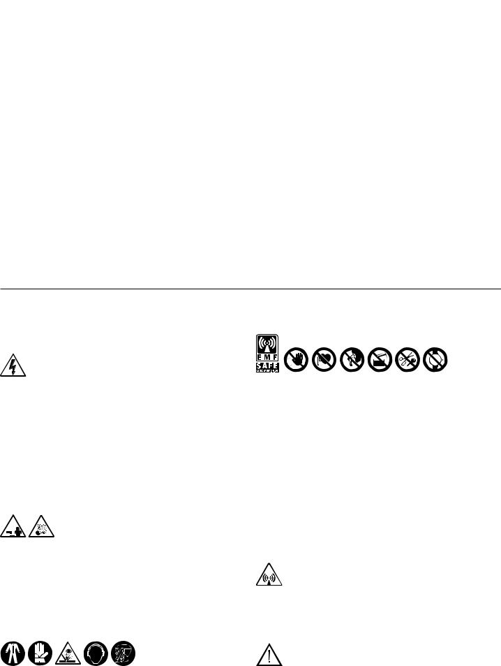
|
|
|
|
|
|
|
|
|
|
|
|
||
FRANÇAIS |
SOMMAIRE |
|
|
|
|
|
|
|
|
|
|
||
1. RÈGLES GÉNÉRALES DE SÉCURITÉ POUR LE SOUDURE À L’ARC |
pag. |
5.5.1 SOUDAGE FIL MIG-MAG |
|
pag. |
|||||||||
............19 |
23 |
||||||||||||
2. INTRODUCTION ET DESCRIPTION GÉNÉRALE............................................... |
|
20 |
5.5.1.1 Connexion de la bouteille de gaz............................................... |
23 |
|||||||||
2.1 INTRODUCTION............................................................................................. |
|
20 |
5.5.1.2 Connexion de la torche.............................................................. |
23 |
|||||||||
2.2 SOUDABILITÉ DES MÉTAUX......................................................................... |
|
20 |
5.5.1.3 Connexion câble de retour du courant de soudage................... |
23 |
|||||||||
2.3 ACCESSOIRES DE SÉRIE............................................................................. |
|
20 |
5.5.2 SOUDAGE TIG...................................................................................... |
23 |
|||||||||
2.4 ACCESSOIRES SUR DEMANDE................................................................... |
|
20 |
5.5.2.1 Connexion à la bonbonne de gaz.............................................. |
23 |
|||||||||
3. DONNÉES TECHNIQUES..................................................................................... |
|
20 |
5.5.2.2 Connexion câble de retour du courant de soudage................... |
23 |
|||||||||
3.1 PLAQUETTE INFORMATIONS....................................................................... |
|
20 |
5.5.2.3 Connexion de la torche.............................................................. |
23 |
|||||||||
3.2 AUTRES INFORMATIONS TECHNIQUES...................................................... |
|
20 |
5.5.3 SOUDAGE AVEC ÉLECTRODE ENROBÉE MMA................................ |
23 |
|||||||||
4. DESCRIPTION DU POSTE DE SOUDAGE.......................................................... |
|
20 |
5.5.3.1 Connexion de la pince porte-électrode...................................... |
23 |
|||||||||
4.1 DISPOSITIFS DE CONTRÔLE, RÉGLAGE ET CONNEXION........................ |
|
20 |
5.5.3.2 Connexion câble de retour du courant de soudage................... |
23 |
|||||||||
4.1.1 Poste de soudage................................................................................... |
|
20 |
5.5.4 RECOMMANDATIONS.......................................................................... |
23 |
|||||||||
4.1.2 Dispositif d’alimentation du fil.................................................................. |
|
21 |
5.6. CHARGEMENT DE LA BOBINE DE FIL........................................................ |
23 |
|||||||||
4.2 PANNEAU DE CONTRÔLE DU POSTE DE SOUDAGE................................ |
|
21 |
5.7 REMPLACEMENT DE LA GAINE GUIDE-FIL DE LA TORCHE...................... |
24 |
|||||||||
4.2.1 PANNEAU DE CONTRÔLE DU DISPOSITIF |
|
|
5.7.1 Gaine à spirale pour fils en acier............................................................ |
24 |
|||||||||
D’ALIMENTATION DU FIL...................................................................... |
|
21 |
5.7.2 Gaine en matière synthétique pour fils en aluminium............................ |
24 |
|||||||||
4.3 RAPPEL ET MÉMORISATION DES PROGRAMMES..................................... |
|
22 |
6.SOUDAGE: DESCRIPTION DU PROCÉDÉ.......................................................... |
24 |
|||||||||
4.3.1 RAPPEL DES PROGRAMMES MÉMORISÉS |
|
|
6.1 SOUDAGE MIG-MAG..................................................................................... |
24 |
|||||||||
PAR LE CONSTRUCTEUR................................................................... |
|
22 |
6.1.1 MODE DE TRANSFERT SHORT ARC (ARC COURT)......................... |
24 |
|||||||||
4.3.1.1 Programmes MIG-MAG SYNERGIQUES.................................. |
|
22 |
6.1.2 MODE DE TRANSFERT SPRAY ARC (PULVÉRISATION AXIALE)..... |
24 |
|||||||||
4.3.1.2 FONCTIONNEMENT EN MANUEL (”PRG 0”)........................... |
|
22 |
6.1.3 MODE DE TRANSFERT PULSE ARC (ARC PULSÉ)........................... |
24 |
|||||||||
4.3.2 MÉMORISATION ET RAPPEL DE PROGRAMMES |
|
|
6.1.4 RÉGLAGE DES PARAMÈTRES DE SOUDAGE |
|
|
||||||||
PERSONNALISÉS EN MIG-MAG......................................................... |
|
22 |
EN MODE DE SOUDAGE MIG-MAG.................................................... |
24 |
|||||||||
4.3.2.1 Introduction................................................................................ |
|
22 |
6.1.4.1 Gaz de protection....................................................................... |
24 |
|||||||||
4.3.2.2 Capacité de mémorisation des programmes |
|
|
6.1.4.2 Courant de soudage.................................................................. |
24 |
|||||||||
personnalisés en MIG-MAG....................................................... |
|
22 |
6.1.4.3 Tension d’arc et réduction de l’arc (pinch-off)............................ |
24 |
|||||||||
4.3.2.3 Procédure de mémorisation (SAVE).......................................... |
|
22 |
6.1.5 FONCTIONNEMENT BI-LEVEL ET PULSE ON PULSE....................... |
24 |
|||||||||
4.3.2.4 Procédure de rappel d’un programme |
|
|
6.2 SOUDAGE TIG (CC)....................................................................................... |
25 |
|||||||||
personnalisé (RECALL)............................................................. |
|
22 |
6.2.1 Amorçage LIFT...................................................................................... |
25 |
|||||||||
5. INSTALLATION..................................................................................................... |
|
23 |
6.3 SOUDAGE AVEC ÉLECTRODE ENROBÉE MMA.......................................... |
25 |
|||||||||
5.1 MISE EN PLACE............................................................................................. |
|
23 |
6.4 QUALITÉ DU SOUDAGE................................................................................ |
25 |
|||||||||
5.2 MODE DE SOULÈVEMENT DU POSTE DE SOUDAGE............................... |
|
23 |
7. ENTRETIEN........................................................................................................... |
25 |
|||||||||
5.3 EMPLACEMENT DU POSTE DE SOUDAGE................................................. |
|
23 |
7.1.1 Torche.................................................................................................... |
25 |
|||||||||
5.4 RACCORDEMENT AU RÉSEAU.................................................................. |
|
23 |
7.1.2 Dispositif d’alimentation du fil................................................................ |
25 |
|||||||||
5.4.1 Avertissements...................................................................................... |
|
23 |
7.2 ENTRETIEN CORRECTIF.............................................................................. |
25 |
|||||||||
5.4.2 Fiche et prise......................................................................................... |
|
23 |
8. ANOMALIES, CAUSES ET SOLUTIONS............................................................. |
25 |
|||||||||
5.5. CONNEXIONS DU CIRCUIT DE SOUDAGE................................................. |
|
23 |
|
|
|
|
|
|
|
|
|
|
|
1. RÈGLES GÉNÉRALES DE SÉCURITÉ POUR LE SOUDURE À L’ARC L’opérateur doit être informé de façon adéquate sur l’utilisation en toute sécurité du poste de soudage, ainsi que sur les risques liés aux procédés de soudage à l’arc, les mesures de précaution et les procédures d’urgence devant être adoptées.
(Se reporter également à la ”SPÉCIFICATION TECHNIQUE CEI ou CLC/TS 62081: INSTALLATION ET UTILISATION DES APPAREILS POUR LE SOUDAGE À L’ARC).
-Éviter tout contact direct avec le circuit de soudage; dans certains cas, la tension à vide fournie par le poste de soudage peut être dangereuse.
-Éteindre le poste de soudage et le débrancher de la prise secteur avant de procéder au branchement des câbles de soudage et aux opérations de contrôle et de réparation.
-Éteindre le poste de soudage et le débrancher de la prise secteur avant de remplacer les pièces de la torche sujettes à usure.
-L’installation électrique doit être effectuée conformément aux normes et à la législation sur la prévention des accidents du travail.
-Le poste de soudage doit exclusivement être connecté à un système d’alimentation avec conducteur le neutre relié à la terre.
-S’assurer que la prise d’alimentation est correctement reliée à la terre.
-Ne pas utiliser le poste de soudage dans des milieux humides, sur des sols mouillés ou sous la pluie.
-Ne pas utiliser de câbles à l’isolation défectueuse ou aux connexions desserrées.
-En cas d’utilisation d’un système de refroidissement liquide, le remplissage d’eau doit être effectué avec le poste de soudage à l’arrêt et débranché du réseau d’alimentation électrique.
-Ne pas souder sur emballages, récipients ou tuyauteries contenant ou ayant contenu des produits inflammables liquides ou gazeux.
-Éviter de souder sur des matériaux nettoyés avec des solvants chlorurés ou à proximité de ce type de produit.
-Ne pas souder sur des récipients sous pression.
-Ne laisser aucun matériau inflammable à proximité du lieu de travail (par exemple bois, papier, chiffons, etc.).
-Prévoir un renouvellement d’air adéquat des locaux ou installer à proximité de l’arc des appareils assurant l’élimination des fumées de soudage; une évaluation systématique des limites d’exposition aux fumées de soudage en fonction de leur composition, de leur concentration et de la durée de l’exposition elle-même est indispensable.
-Protéger la bonbonne de gaz des sources de chaleur, y compris des rayons UV (si prévue).
-Prévoir un isolement électrique adéquat de l’électrode, de la pièce en cours de traitement, et des éventuelles parties métalliques se trouvant à proximité (accessibles). Cet isolement est généralement assuré au moyen de gants, de chaussures de sécurité et autres spécifiquement prévus, ainsi que de plateformes ou de tapis isolants.
-Toujours protéger les yeux au moyen de verres inactiniques spéciaux montés sur le masque ou le casque. Utiliser des gants et des vêtements de protection afin d’éviter d’exposer l’épiderme aux rayons ultraviolets produits par l’arc. Ces mesures de protection doivent également être étendues à toute
personne se trouvant à proximité de l’arc au moyen d’écrans ou de rideaux non réfléchissants.
-Bruit: si, du fait d’opérations de soudage particulièrement intensives, le niveau d’exposition quotidienne personnelle (LEPd) est égal ou supérieur
à85db (A), l’utilisation de moyens de protection individuelle adéquats est obligatoire.
-Le passage du courant de soudage génère des champs électromagnétiques (EMF) localisés aux alentours du circuit de soudage.
Ces champs électromagnétiques risquent de créer des interférences avec certains appareils médicaux (ex. pace-maker, respirateurs, prothèses métalliques, etc.)
Des mesures de protection doivent être adoptées pour les porteurs de ces appareils. L’une d’elles consiste à interdire l’accès à la zone d’utilisation du poste de soudage.
Ce poste de soudage répond aux exigences des normes techniques de produit pour une utilisation exclusive dans des environnements industriels à usage professionnel. La conformité aux limites de base relatives à l’exposition humaine aux champs électromagnétiques en environnement domestique n’est pas garantie.
L’opérateur doit utiliser les procédures suivantes de façon à réduire l’exposition aux champs électromagnétiques :
-Fixer les deux câbles de soudage l’un à l’autre et les plus près possible.
-Garder sa tête et son buste le plus loin possible du circuit de soudage.
-Ne jamais placer les câbles de soudage autour de son corps.
-Ne pas se placer au milieu du circuit de soudage durant les opérations. Placer les deux câbles du même côté du corps.
-Connecter le câble de retour du courant de soudage à la pièce à souder, le plus près possible du raccord en cours d’exécution.
-Ne pas souder à proximité, assis ou appuyé sur le poste de soudage (distance minimale : 50cm).
-Ne pas laisser d’objets ferromagnétiques à proximité du circuit de soudage.
-Distance minimale d = 20cm (Fig. N).
-Appareils de classe A :
Ce poste de soudage répond aux exigences de la norme technique de produit pour une utilisation exclusive dans des environnements industriels à usage professionnel. La conformité à la compatibilité électromagnétique dans les immeubles domestiques et dans ceux directement raccordés à un réseau d’alimentation basse tension des immeubles pour usage domestique n’est pas garantie.
PRÉCAUTIONS SUPPLÉMENTAIRES
-TOUTE OPÉRATION DE SOUDAGE:
-Dans des lieux comportant des risques accrus de choc électrique
-Dans des lieux fermés
-En présence de matériaux inflammables ou comportant des risques d’explosion
DOIT être soumise à l’approbation préalable d’un ”Responsable expert”, et toujours effectuée en présence d’autres personnes formées pour intervenir en cas d’urgence.
- 19 -
Les moyens techniques de protection décrits aux points 5.10; A.7; A.9. de la ”SPÉCIFICATION TECHNIQUE CLC/TS (CEI) 62081” DOIVENT être adoptés.
-NE JAMAIS procéder au soudage si le poste de soudage ou le dispositif d’alimentation du fil est maintenu par l’opérateur (par ex. au moyen de courroies).
-Tout soudage par l’opérateur en position surélevée est interdit, sauf en cas d’utilisation de plates-formes de sécurité.
-TENSION ENTRE PORTE-ÉLECTRODE OU TORCHES: toute intervention effectuée avec plusieurs postes de soudage sur la même pièce ou sur plusieurs pièces connectées électriquement peut entraîner une accumulation de tension à vide dangereuse entre deux porte-électrode ou torches pouvant atteindre le double de la limite admissible.
Il est indispensable qu’un coordinateur expert procède à la mesure des instruments pour déterminer la présence effective de risques, et adopte des mesures de protection adéquates, comme indiqué au point 5.9 de la SPÉCIFICATION TECHNIQUE CLC/TS 62081.
RISQUES RÉSIDUELS
-RENVERSEMENT: Installer le poste de soudage sur une surface horizontale de portée adéquate pour éviter tout risque de renversement (par ex. en cas de sol incliné ou irrégulier, etc.).
-Il est interdit de soulever l’unité chariot avec poste de soudage, dispositif d’alimentation du fil et groupe de refroidissement (si prévu).
-La seule opération de soulèvement AUTORISÉE est celle prévue dans la section ”INSTALLATION” de ce manuel.
-UTILISATION INCORRECTE: il est dangereux d’utiliser le poste de soudage pour d’autres applications que celles prévues (ex.: décongélation des tuyauteries du réseau hydrique.)
-DÉPLACEMENT DU POSTE DE SOUDAGE ET DE SON CHARIOT : toujours fixer la bouteille de façon adéquate afin d’empêcher toute chute accidentelle.
Les protections et les parties mobiles de la structure du poste de soudage et du dispositif d’alimentation du fil doivent être installées avant de brancher le poste de soudage au réseau secteur.
ATTENTION!Touteinterventionmanuelleeffectuéesurlespartiesenmouvement du dispositif d’alimentation du fil, comme par exemple:
-Remplacement des rouleaux et/ou du guide-fil
-Introduction du fil dans les rouleaux
-Chargement de la bobine de fil
-Nettoyage des rouleaux, des engrenages et de la partie située en dessous de ces derniers
-Lubrification des engrenages
DOITÊTREEFFECTUÉEAVECLEPOSTEDESOUDAGEÉTEINTETDÉBRANCHÉ DU RÉSEAU D’ALIMENTATION ÉLECTRIQUE.
2. INTRODUCTION ET DESCRIPTION GÉNÉRALE
2.1 INTRODUCTION
Ce poste de soudage comprend une alimentation en énergie électrique et un dispositif d’alimentation du fil incorporé. La source de courant est un redresseur à alimentation triphasée multiprocédés (MIG-MAG SYNERGIQUE continu ou pulsé, TIG et MMA) avec réglage électronique (mode commutation) contrôlé par microprocesseur avec pont entier côté primaire. Le dispositif d’alimentation du fil est équipé d’un groupe d’entraînement du fil à 4 rouleaux motorisés avec régulation indépendante de la pression d’entraînement: le panneau de contrôle numérique, auquel est incorporée la carte de régulation à microprocesseur, remplit trois fonctions essentielles:
a)CONFIGURATION ET RÉGLAGE DES PARAMÈTRES
Cette interface utilisateur permet la configuration et le réglage des paramètres d’exploitation, la sélection des programmes mémorisés, l’affichage sur écran de l’état et de la valeur des paramètres.
b)RAPPEL DE PROGRAMMES SYNERGIQUES PRÉMÉMORISÉS POUR SOUDAGE MIG-MAG
Ces programmes ont été prédéfinis et mémorisés par le constructeur et ne peuvent donc être modifiés; le rappel de l’un de ces programmes permet à l’utilisateur de sélectionner un point d’intervention précis (correspondant à un groupe de différents paramètres de soudage indépendants) en régulant une seule grandeur. Tel est le concept de SYNERGIE, lequel permet d’obtenir sans aucune difficulté une régulation optimale du poste de soudage en fonction de la spécificité des différentes conditions opérationnelles.
c)MÉMORISATION ET RAPPEL DE PROGRAMMES PERSONNALISÉS
Cette fonction est disponible tant dans le contexte d’un programme synergique qu’en mode manuel (dans ce dernier cas, la configuration de tous les paramètres de soudage est arbitraire.) Ce mode de fonctionnement permet à l’utilisateur de mémoriser puis de rappeler un soudage spécifique.
2.2 SOUDABILITÉ DES MÉTAUX
MIG-MAG Le poste de soudage est indiqué pour le soudage MIG de l’aluminium et des alliages d’aluminium, le brasage MIG, typiquement effectué sur des tôles zinguées, et le soudage MAG des aciers au carbone, alliages d’acier léger et aciers inox. Le soudage MIG de l’aluminium et des alliages d’aluminium doit être effectué en utilisant des fils fourrés à la composition compatible avec le matériau à souder et un gaz de protection Ar pur (99,9%).
Le brasage MIG type s’effectue sur des tôles zinguées en utilisant des fils pleins en alliage de cuivre (ex. cuivre silicium ou cuivre aluminium) avec gaz de protection Ar pur (99,9%).
Le soudage MAG des aciers au carbone et des alliages légers doit être effectué en utilisant des fils pleins ou fourrés ayant une composition compatible avec le matériau à souder et un gaz de protection CO2 mélanges Ar/CO2 ou Ar/CO2-O2 (Argon typiquement > 80%).
Pour le soudage des aciers inox sont généralement utilisés des mélanges de gaz Ar/ O2 ou Ar/CO2 (Ar typiquement>98%).
TIG Le poste de soudage est prévu pour un soudage TIG en courant continu (CC) avec amorçage de l’arc par contact (mode LIFT ARC) pouvant être utilisé avec tous les types d’acier (au carbone, bas-alliés et fortement alliés) et des métaux lourds (cuivre, nickel, titane et leurs alliages) avec gaz de protection Ar pur (99,9%) ou bien, pour des utilisations particulières, avec des mélanges Argon/Hélium.
MMA Le poste de soudage est prévu pour le soudage avec électrode MMA en courant continu (CC) avec tous les types d’électrodes enrobées.
2.3ACCESSOIRES DE SÉRIE
- Adaptateur bouteille Argon.
- Câble de retour avec pince de masse. - Réducteur de pression 2 manomètres. - Kit câbles de connexion 1,5m.
- Groupe de refroidissement à l’eau G.R.A. (version R.A. uniquement)
- Torche MIG
(refroidie à l’eau pour la version R.A.). - Dispositif d’alimentation du fil.
- Kit couvre-bobine. - Chariot
2.4ACCESSOIRES SUR DEMANDE
-Commande à distance manuelle à 1 potentiomètre. (TIG et MMA uniquement).
-Commande à distance manuelle à 2 potentiomètres.
-Commande à pédale (MMA et TIG uniquement).
-Groupe de refroidissement à l’eau G.R.A. (accessoire de série version R.A. uniquement).
-Kit câbles de connexion R.A. 4m, 10m, 30m.
-Kit câbles de connexion 4 et 10m.
-Kit roues dispositif d’alimentation du fil.
-Kit soudage aluminium.
-Kit soudage fil fourré.
-Kit soudage MMA 600A.
-Torche MIG 5m 500A.
-Torche MIG 3m 500A R.A.
(accessoire de série version R.A. uniquement).
-Torche MIG 5m 500A R.A.
-Torche TIG 4 ou 8m, 220A.
-Torche TIG 4 ou 8m, 350A R.A.
-Torche MIG/TIG UP/DOWN avec/sans potentiomètre.
-Torche PUSH PULL.
-Torche avec câble sériel 485.
-Kit double bouteille.
3. DONNÉES TECHNIQUES
3.1 PLAQUETTE INFORMATIONS (FIG. A)
Les principales informations concernant les performances du poste de soudage sont résumées sur la plaque des caractéristiques avec la signification suivante:
1- Degré de protection de la structure.
2- Symbole de la ligne d’alimentation. 1~: tension alternative monophasée; 3~: tension alternative triphasée.
3- Symbole S: indique qu’il est possible d’effectuer des opérations de soudage dans un milieu présentant des risques accrus de choc électrique (par ex. à proximité immédiate de grandes masses métalliques).
4- Symbole du procédé de soudage prévu.
5- Symbole de la structure interne du poste de soudage.
6- Norme EUROPÉENNE de référence pour la sécurité et la construction des postes de soudages pour soudage à l’arc.
7- Numéro d’immatriculation pour l’identification du poste de soudage (indispensable en cas de nécessité d’assistance technique, demande pièces de rechange, recherche provenance du produit).
8- Performances du circuit de soudage:
-U0 : Tension maximale à vide (circuit de soudage ouvert).
-I2/U2 : Courant et tension correspondante normalisée pouvant être distribués par la machine durant le soudage.
-X: Rapport d’intermittence: indique le temps durant lequel la machine peut distribuer le courant correspondant (même colonne). S’exprime en % sur la base d’un cycle de 10 minutes (par ex.: 60% = 6 minutes de travail, 4 minutes de pause; et ainsi de suite).
En cas de dépassement des facteurs d’utilisation (figurant sur la plaquette et indiquant 40°), la protection thermique se déclenche et le poste de soudage se place en veille tant que la température ne rentre pas dans les limites autorisées.
-A/V - A/V: indique la plage de régulation du courant de soudage (minimum - maximum) à la tension d’arc correspondante.
9- Informations caractéristiques de la ligne d’alimentation:
- U1: tension alternative et fréquence d’alimentation du poste de soudage (limites |
|
|
admises ± 10%). |
- l1max: courant maximal absorbé par la ligne. |
|
- |
I1eff: courant d’alimentation efficace. |
10- |
:Valeur des fusibles à commande retardée à prévoir pour la protection |
de la ligne.
11- Symboles se référant aux normes de sécurité dont la signification figure au chapitre 1 “Régles générales de sécurité pour le soudage à l’arc ”.
Note: La plaquette représentée indique la signification des symboles et des chiffres; les valeurs exactes des informations techniques du poste de soudage doivent être vérifiées directement sur la plaquette du poste de soudage.
3.2 AUTRES INFORMATIONS TECHNIQUES |
voir tableau (TAB.1) |
|
- |
POSTE DE SOUDAGE : |
|
- |
TORCHE: |
voir tableau (TAB.2A). |
- |
DISPOSITIF D’ALIMENTATION DU FIL: |
voir tableau (TAB.2B). |
4. DESCRIPTION DU POSTE DE SOUDAGE.
4.1 DISPOSITIFS DE CONTRÔLE, RÉGULATION ET CONNEXION
4.1.1Poste de soudage (FIG. B1)
àl’avant :
1- Panneau de contrôle (voir description).
2- Prise rapide négative (-) pour câble courant de soudage (câble de masse pour MIG et MMA, câble torche pour TIG).
3- Raccord gaz pour torche TIG.
4- Connecteur 3p pour câble contrôle TORCHE TIG.
5- Connecteur 14p pour connexion de la commande à distance (sur demande). 6- Prise rapide positive (+) pour câble de masse soudage TIG.
à l’arrière :
7- Interrupteur général ON/OFF.
8- Raccord tube gaz (bouteille) pour soudage TIG.
9- Prise rapide positive (+) pour câble courant de soudage vers le dispositif d’alimentation du fil.
10Connecteur 14p pour câble de commande dispositif d’alimentation du fil. 11Câble d’alimentation avec presse-câble.
12Connecteur 5p pour groupe de refroidissement à l’eau.
- 20 -
13Fusible.
14Prise USB.
4.1.2Dispositif d’alimentation du fil (FIG. B2)
àl’avant :
1- Panneau de contrôle (voir description).
2- Connecteur 14p pour connexion de la commande à distance. 3- Raccords rapides pour conduites eau de la torche MIG.
4- Connexion centralisée pour torche MIG (Euro).
à l’arrière :
5- Connecteur 14p pour câble de commande avec le poste de soudage.
6- Prise rapide positive (+) pour connexion câble courant de soudage vers le poste de soudage.
7- Raccord tube gaz (bouteille) pour soudage MIG.
8- Raccords rapides pour connexion tubes refoulement et retour eau de refroidissement.
9- Fusible.
4.2 PANNEAU DE CONTRÔLE DU POSTE DE SOUDAGE (FIG. C)
Le panneau de contrôle est activé (les commandes et signalisations sont activées) uniquement si le poste de soudage n’est pas connecté au dispositif d’alimentation du fil ou si le procédé MMA ou TIG est configuré. Si le poste de soudage est connecté au dispositif d’alimentation du fil ou si la fonction MIG est configurée, ce dernier effectue alors automatiquement le contrôle complet et l’écran (3) du poste de soudage affiche alors “feed”.
1- DEL de signalisation Alarme (la sortie du poste de soudage est bloquée). Sur l’écran (3) s’affiche un message d’alarme.
Le rétablissement est automatique dès disparition de la cause de l’alarme.
2- DEL présence de tension en sortie (sortie activée) 3- Affichage alphanumérique à 3 chiffres. Indique :
-Courant de soudage exprimé en ampères.
La valeur indiquée est celle définie avec le poste de soudage à vide, mais est la valeur réelle durant le fonctionnement.
-Un message d’alarme avec le code suivant :
-”AL1” : intervention protection thermique du circuit primaire.
-”AL2” : intervention protection thermique du circuit secondaire.
-”AL3” : intervention protection pour surtension de la ligne d’alimentation.
-”AL4” : intervention protection pour sous-tension ligne d’alimentation
-”AL5” : modèle à GRA : intervention protection pour pression insuffisante du circuit de refroidissement à l’eau de la torche. Le rétablissement n’est pas automatique.
modèle sans GRA : connecteur de polarisation machine non connecté (FIG. E).
-“AL9” : intervention protection composants magnétiques.
-“AL10” : panne ligne sérielle : ligne sérielle déconnectée.
-“AL11” : intervention protection pour manque de phase de la ligne
d’alimentation.
-“AL12” : panne ligne sérielle : erreur de données.
-“AL13” : dépôt de poussière excessif à l’intérieur du poste de soudage,
rétablissement avec :
-nettoyage interne de la machine ;
-touche de sélection paramètres du panneau de contrôle.
Lors de l’extinction du poste de soudage, les messages ”AL11” et “OFF” peuvent s’afficher durant quelques secondes..
3a, 3b, 3c - DEL d’indication de l’unité de mesure en cours (ampères, secondes et pourcentage.)
4- Poignée de commande codeur.
Permet de régler les paramètres de soudage (4a).
: Courant de soudage en mode TIG/MMA.
: En mode TIG, permet la réduction graduelle du courant sur 

 relâchement du poussoir torche (réglage 0-3 secondes) et DEL
(3b) allumée.
: En mode TIG, prend la signification de “Post-gas” et permet d’adapter le temps de flux sortant du gaz de protection à partir de l’arrêt du soudage (réglage 0,1-10 secondes et DEL (3b) allumée).
: Exclusivement activé si le mode “SPOT” a été sélectionné au moyen de la touche (7). Permet l’exécution de pointages en mode TIG avec contrôle de la durée du soudage (régulation 0,1- 10 secondes et DEL (3b) allumée).
: En fonctionnement avec électrode MMA, le paramètre prend la signification de “Arc force” et permet la définition de la surintensité
dynamique (régulation 0-100% et DEL (3c) allumée).
5- Touche de sélection du procédé de soudage.
La pression de la touche entraîne l’allumage de la DEL correspondant au mode de soudage que l’on désire adopter :
: |
électrode enrobée “MMA”. |
: TIG-DC avec amorçage de l’arc par contact (LIFT-ARC). |
|
: |
MIG. |
6- Touche d’introduction de la commande à distance. |
|
Avec la DEL |
allumée, la régulation peut exclusivement être effectuée |
à partir de la commande à distance et, plus en détail :
a)Commande à un potentiomètre : permet le réglage du courant de soudage en mode TIG/MMA.
b)Commande deux potentiomètres : permet le réglage du courant de soudage TIG/MMA et le réglage du SLOPE DOWN en TIG ou ARC FORCE en MMA (sélection DEL paramètre automatique).
c)Commande à pédale: permet le réglage du courant de soudage en mode TIG/MMA.
REMARQUE : La sélection «À DISTANCE“ (REMOTE) n’est possible que si une commande à distance est effectivement connectée à son connecteur.
7- Touche de sélection du mode de contrôle du poussoir torche TIG.
La pression de la touche entraîne l’allumage de la DEL correspondant aux fonctionnements suivants :
: fonctionnement à 2 temps, ON-OFF avec poussoir enfoncé.
: fonctionnement à 4 temps, ON-OFF avec poussoir relâché.
: fonctionnement en pointage TIG (SPOT).
4.2.1PANNEAU DE CONTRÔLE DU DISPOSITIF D’ALIMENTATION DU FIL (FIG. D)
1- DEL de signalisation ALARME (la sortie de la machine est bloquée). Le rétablissement est automatique dès disparition de la cause de l’alarme. Messages d’alarme indiqués sur les écrans (15) et (16) :
-“AL7” : intervention protection pour surintensité en mode de soudage MIG/ MAG.
-“AL8” : panne ligne sérielle : court-circuit sur torche.
Pour les autres cas, voir “PANNEAU DE CONTRÔLE DU POSTE DE SOUDAGE” (par. 4.2).
2- DEL de signalisation PRÉSENCE DE TENSION SUR TORCHE OU ÉLECTRODE.
3- DEL de signalisation PROGRAMMATION POSTE DE SOUDAGE.
4 - Touche de rappel (RECALL) des programmes de soudage personnalisés (voir par. 4.3.2.4).
5- Touche de mémorisation (SAVE) des programmes de soudage personnalisés (voir par. 4.3.2.3).
6- Touche de sélection programme de soudage et affichage à 2 chiffres.
La pression de la touche à plusieurs reprises entraîne l’affichage de numéros compris entre “0” et “36”. À chaque numéro compris entre “1” et “36” est associé un programme de soudage synergique (voir TAB. 3) tandis que le numéro “0” est associé au fonctionnement manuel du poste de soudage permettant à l’opérateur de configurer tous les paramètres (MIG/MAG SHORT et SPRAYARC uniquement).
7- Touche de sélection du procédé de soudage.
La pression de la touche entraîne l’allumage de la DEL correspondant au mode de soudage que l’on désire adopter :
: MIG/MAG en mode “SHORT/SPRAY ARC”.
: MIG/MAG en mode “PULSE ARC”.
: MIG/MAG en mode “PULSE ON PULSE”.
8- Touche de sélection du mode de contrôle du poussoir torche MIG/MAG.
La pression de la touche entraîne l’allumage de la DEL correspondant aux fonctionnements suivants :
: fonctionnement à 2 temps, ON-OFF avec poussoir enfoncé.
: fonctionnement à 4 temps, ON-OFF avec poussoir relâché.
: fonctionnement bi-level pour MIG/MAG, TIG.
: fonctionnement en pointage MIG-MAG (SPOT).
9- Touche d’introduction de la commande à distance.
Avec la DEL 


 allumée, la régulation peut exclusivement être effectuée à partir de la commande à distance et, plus en détail :
- commande deux potentiomètres : remplace la fonction des boutons codeur
(14) et (13).
REMARQUE : La sélection «À DISTANCE“ (REMOTE) n’est possible que si une commande à distance est effectivement connectée à son connecteur.
10Touche de sélection des paramètres de soudage.
La pression de la touche en séquence entraîne l’allumage de l’une des DEL de (10a) à (10h) à laquelle est associé un paramètre spécifique. La configuration de la valeur de chaque paramètre activé peut être effectuée au moyen du bouton (13) et indiquée sur l’écran (15). Durant ces configurations, le bouton (14) règle la valeur du niveau principal de soudage indiqué sur l’écran (16), courant ou vitesse fil (voir description point (14)), sauf pour (10b).
Uniquement avec la DEL (10b) allumée, le bouton (14) permet de régler la valeur du niveau secondaire (voir description DEL (10b)).
Remarque : les paramètres non modifiables par l’opérateur, en fonction du fait que l’on utilise un programme synergique ou le mode manuel “PRG 0”, sont automatiquement exclus de la sélection ; la DEL correspondante ne s’allume pas.
10a- 


Ce paramètre s’affiche automatiquement durant les opérations de soudage MIG/ MAG et indique la tension réelle de l’arc (DEL (15a) allumée).
Réglages :
 Short arc
Durant la définition d’un programme synergique MIG-MAG, Short arc permet de régler la correction devant être apportée à la longueur de l’arc calculée en synergie (plage de -5% à +5%) (DEL (15c) allumée).
Dans la même condition, en configurant la fonction bi-level, le paramètre prend la signification de correction de la longueur d’arc du niveau principal de soudage, toujours calculée en synergie (plage de -5% à +5%) (DEL (15c) allumée)
 Short arc “PRG 0”
Toujours en fonctionnement MIG-MAG Short arc, le programme manuel “PRG 0” permet de configurer la tension d’arc effective (plage 10-40)(DEL (15a) allumée). Dans la même condition, en configurant la fonction bi-level, le paramètre prend la signification de tension d’arc effective du niveau principal de soudage (plage10-40) (DEL (15a) allumée)
Durant la définition d’un programme synergique MIG-MAG Pulse arc permet de régler la correction devant être apportée à la longueur de l’arc calculée en synergie (plage de -5% a +5%) (DEL (15c) allumée).
Dans la même condition, en configurant la fonction bi-level, pulse on pulse ou Tstart, le paramètre prend la signification de correction de la longueur d’arc du niveau principal de soudage, toujours calculée en synergie (plage de -5% à +5%) (DEL (15c) allumée).
10b- 


 Short arc
Avec les programmes synergiques MIG-MAG short arc, la configuration de la fonction bi-level permet de régler le courant/la vitesse du fil (bouton (14)) et la correction de la longueur d’arc (bouton (13)) du niveau secondaire de soudage calculée en synergie (place de -5% à +5%)(DEL (15c) allumée).
 Short arc “PRG 0”
La sélection du programme manuel (“PRG 0”) avec fonction bi-level permet de régler la vitesse du fil (bouton (14)(DEL 16c) allumée) et la tension d’arc effective
- 21 -

(bouton (13)) du niveau secondaire I1 de soudage (plage 10-40)((DEL (15a) allumée).
En mode MIG-MAG pulse arc, la configuration des fonctions bi-level, pulse on pulse ou Tstart permet de régler le courant I1 et IS (Istart) (bouton (14)) et la correction de la longueur d’arc (bouton (13)) du niveau secondaire de soudage calculé en synergie (plage de -5% à +5%)(DEL (15c) allumée).
10c- 


 Short arc “PRG 0”
En mode manuel “PRG 0”, permet d’adapter la vitesse du fil au démarrage du soudage pour optimiser l’amorçage de l’arc (régulation 1-100% et DEL (15c) allumée).
En mode MIG-MAG Pulse arc 2 TEMPS, permet de régler la durée du courant initial (Tstart). Le réglage du paramètre à zéro désactive la fonction, tandis qu’une valeur supérieure à zéro (réglage 0,1-3 secondes) permet de sélectionner la DEL (10b) pour régler la correction de la tension d’arc et la valeur du courant initial (niveau secondaire). Le courant initial peut être configuré plus élevé ou plus bas que le courant principal de soudage ; un courant initial plus élevé est très utile, en particulier pour le soudage de l’aluminium et de ses alliages car il permet un chauffage plus rapide de la pièce (“Hot-start”).
En mode MIG-MAG Pulse on pulse, permet de régler la durée du courant principal de soudage (réglage 0,1-10 secondes et DEL (15b) allumée).
10d- 

 Short arc “PRG 0”
En mode manuel MIG-MAG “PRG 0”, permet de régler la réactance électronique (réglage 20-80% et DEL (15c) allumée). Une valeur plus élevée entraîne un bain de soudage plus chaud. En mode bi-level, la réactance électronique est commune aux deux niveaux configurés.
En mode MIG-MAG pulse arc, le paramètre entraîne l’étranglement de l’arc. Plus la valeur est élevée, et plus l’arc est concentré durant le soudage. Avec un mode de soudage utilisant deux niveaux de courant (bi-level, pulse on pulse ou Tstart), l’étranglement d’arc est commun aux deux niveaux configurés (+1% / -1%).
En mode MIG/MAG Pulse on pulse, permet de régler la durée du courant secondaire de soudage (réglage 0,1-10 secondes et DEL (15b) allumée).
10e-
Brûlure du fil à l’arrêt du soudage (BURN-BACK).
Permet de régler le temps de brûlure du fil à l’arrêt du soudage.
Durant la définition d’un programme synergique MIG/MAG, permet de régler la correction devant être apportée au BURN_BACK TIME calculée en synergie (plage de -1% à +1%) (DEL (15c) allumée).
 Short arc “PRG 0”
Une configuration adaptée permet d’éviter tout collage du fil à la pièce en mode manuel (réglage 0,001-1 seconde et DEL (15b) allumée).
10f-
Post-gas
Permet d’adapter le temps de flux sortant du gaz de protection à partir de l’arrêt du soudage (régulation 0,1-10 secondes et DEL (15b) allumée).
10g-
Rampe de descente courant de soudage (SLOPE DOWN).
Est uniquement activée avec l’utilisation de programmes synergiques MIG-MAG Short arc, Pulse arc et Pulse on Pulse.
Permet la réduction graduelle du courant avec le relâchement du poussoir torche (régulation 0-3 secondes et DEL (15b) allumée).
10h-
Temps de pointage (SPOT TIME).
Exclusivement activé si le mode “SPOT” a été sélectionné au moyen de la touche (8). Permet l’exécution de pointages en mode MIG-MAG avec contrôle de la durée du soudage (régulation 0,1-10 secondes et DEL (15b) allumée).
11Touche d’activation manuelle de l’électrovanne gaz.
La touche permet le flux sortant de gaz (purge conduites - réglage débit) sans besoin d’utiliser le poussoir torche ; la touche est à action momentanée.
12Touche d’avancement manuel du fil.
La touche permet de faire avancer le fil dans la gaine de la torche sans nécessité d’utiliser le poussoir torche ; la touche est à action momentanée et la vitesse d’avancement est fixe.
13Bouton codeur pour la régulation des paramètres de soudage (voir 10a-10h).
14Bouton codeur.
Le bouton permet de régler :
-Le courant de soudage I2 (DEL (16a) allumée).
-La vitesse d’avancement du fil (DEL (16c) allumée).
-L’épaisseur de la pièce utilisée pour le soudage (DEL (16b) allumée).
En mode de soudage utilisant deux niveaux de courant (bi-level, pulse on pulse ou Tstart) avec la DEL (10b) allumée, le bouton règle :
- Le courant de soudage I1 (DEL (I6a) allumée) du niveau secondaire.
- La vitesse d’avancement du fil secondaire de soudage (DEL (16c) allumée). - L’épaisseur de la pièce utilisée pour le soudage (DEL (16b) allumée) correspondant au niveau secondaire.
15Affichage alphanumérique à 3 chiffres. Indique :
-la valeur des paramètres de soudage (voir de (10a) à (10h)) avec fonctionnement à vide.
-la tension réelle de l’arc en cours de soudage.
REMARQUE : à la fin du soudage, l’écran commute automatiquement à la valeur de configuration.
- une signalisation d’alarme (voir point 1).
15a, 15b, 15c - DEL d’indication de l’unité de mesure en cours (volts, secondes et pourcentage.)
16Affichage alphanumérique à 3 chiffres. Indique :
-la valeur définie avec le bouton codeur (14).
-le courant réel durant le soudage.
REMARQUE : à la fin du soudage, l’écran commute automatiquement à la valeur de configuration.
- une signalisation d’alarme (voir point 1).
16a, 16b, 16cDEL d’indication unité de mesure en cours (courant ampères (A), épaisseur en millimètres (mm) et vitesse fil en mètres/minute (m/min)).
17Touche de sélection unité de mesure ampères/épaisseur en m/min (DEL(16a)(16b) (16c)).
Dans les programmes synergiques MIG/MAG, permet, au moyen du codeur (14), de configurer respectivement l’épaisseur du matériau à souder, le courant de soudage et la vitesse du fil.
La configuration de chaque paramètre (ex. épaisseur du matériau) définit automatiquement les autres paramètres (ex. courant de soudage et vitesse du fil).
“PRG 0” sélection manuelle : seul le réglage de la vitesse du fil est possible (DEL (16c) allumée).
4.3 RAPPEL ET MÉMORISATION DES PROGRAMMES
4.3.1 RAPPEL DES PROGRAMMES MÉMORISÉS PAR LE CONSTRUCTEUR 4.3.1.1 Programmes MIG-MAG SYNERGIQUES
Le poste de soudage prévoit 36 programmes synergiques mémorisés, dont les caractéristiques sont identifiées sur le tableau (TAB.3) auquel se reporter pour la sélection du programme correspondant au type de soudage devant être exécuté.
La sélection d’un programme déterminé s’effectue en pressant en séquence la touche ”PRG”, à laquelle correspond sur l’écran un numéro compris entre ”0” et ”36” (à ”0” ne correspond pas un programme synergique, mais le fonctionnement en mode manuel, comme décrit au paragraphe suivant.)
Remarque: À l’intérieur d’un programme synergique, procéder en priorité à la sélection du mode de transfert désiré, PULSE ARC ou SHORT/SPRAY ARC, au moyen de la touche prévue (voir FIG. D, touche (7)).
Remarque: Tous les types de fils non prévus sur le tableau peuvent être utilisés en mode manuel ”PRG 0”.
4.3.1.2 FONCTIONNEMENT EN MANUEL (”PRG 0”)
Le fonctionnement en mode manuel correspond au ”0” de l’écran, et n’est activé que si le mode de transfert SHORT/SPRAY ARC (FIG. D, touche (7)) a été sélectionné. Avec ce mode, aucune synergie n’étant prévue, tous les paramètres de soudage doivent être configurés manuellement par l’opérateur.
Attention ! La configuration de tous les paramètres est libre si les valeurs attribuées à ces derniers sont compatibles avec un procédé de soudage correct.
Remarque: Le mode de transfert PULSE ARC NE PEUT être utilisé en sélection manuelle.
4.3.2 MÉMORISATION ET RAPPEL DE PROGRAMMES PERSONNALISÉS EN MIG-MAG
4.3.2.1 Introduction
Le poste de soudage permet de mémoriser (SAVE) des programmes de travail personnalisés correspondant à un JEU de paramètres valides pour un soudage donné. Chacun des programmes mémorisés peut être rappelé (RECALL) à tout moment, l’opérateur disposant ainsi d’un poste de soudage ”prêt à l’utilisation” pour un travail spécifique optimisé précédemment.
4.3.2.2Capacité de mémorisation des programmes personnalisés en MIG-MAG
Le poste de soudage prévoit la mémorisation de 40 programmes personnalisés en trois modes de transfert en synergie (SHORT/SPRAY ARC Pulse arc et Pulse on pulse) et au fonctionnement en mode manuel présentant les caractéristiques suivantes :
- SHORT/SPRAY ARC SYNERGIQUE : 10 programmes mémorisables (numéros disponibles de “1” à “10”),
- SHORT/SPRAY ARC MANUEL («PRG=0») : 10 programmes mémorisables (nombres disponibles de “1” à “10”).
- PULSE ARC SYNERGIQUE : 10 programmes mémorisables (numéros disponibles de “1” à “10”),
- PULSE ARC SYNERGIQUE PULSE ON PULSE : 10 programmes mémorisables (numéros disponibles de “1” à “10”),
REMARQUE : Pour rappeler le programme devant être utilisé :
a) sélectionner le mode de transfert requis PULSE ARC, PULSE ARC PULSEON- PULSE ou SHORT/SPRAY ARC, ou bien sélectionner “PRG=0” en cas de programmes pré-mémorisés en mode manuel ;
b) sélectionner le numéro du programme (voir par.4.3.1).
4.3.2.3Procédure de mémorisation (SAVE).
Après avoir réglé le poste de soudage de façon optimale en vue d’un soudage déterminé, procéder comme suit (FIG. D):
a)Enfoncer la touche (5) ”SAVE”.
b)”Pr” apparaît sur l’écran (16), et un numéro (compris entre ”1” et ”10”) apparaît sur l’écran (15).
c)Tourner le bouton codeur (indifféremment le (13) ou le (14)), et sélectionner le numéro pour la mémorisation du programme (voir également 4.3.2 ).
d)Enfoncer à nouveau la touche ”SAVE”.
e)Les écrans (15) et (16) clignotent.
f)Enfoncer à nouveau, dans un délai maximal de deux secondes, la touche ”SAVE”.
g)Sur les écrans apparaît ”St Pr”, indiquant que le programme a été mémorisé ; après 2 secondes, les écrans commutent automatiquement sur les valeurs correspondant aux paramètres venant d’être mémorisés.
Remarque: Si, en cas de clignotement de l’écran, la touche ”SAVE” n’est pas à nouveau pressée dans un délai de 2 secondes, les écrans indiquent ”No St” et le programme n’est pas mémorisé ; les écrans reviennent automatiquement à l’indication initiale.
4.3.2.4 Procédure de rappel d’un programme personnalisé (RECALL)
Avant de procéder aux opérations de rappel d’un programme, contrôler que le mode de transfert sélectionné (ARC PULSÉ, ARC PULSÉ PULSE-ON-PULSE, SHORT/ SPRY ARC ou “PRG=0”) est effectivement celui que l’on a l’intention d’utiliser. Procéder ensuite de la façon suivante (FIG. D):
a)Enfoncer la touche ”RECALL”.
b)”Pr” apparaît sur l’écran (16) et un numéro (compris entre ”1” et ”10”) sur l’écran
(15).
c)Tourner le bouton codeur (indifféremment le (13) ou le (14)), et sélectionner le numéro sous lequel a été mémorisé le programme devant être utilisé.
- 22 -
d)Enfoncer à nouveau la touche ”RECALL” durant plus de 2 secondes.
e)Sur les écrans apparaît ”Ld Pr”, indiquant que le programme a été rappelé; les écrans commutent automatiquement après 2 secondes sur les valeurs correspondant au programme venant d’être rappelé.
Remarque: Si la touche ”RECALL” n’est pas pressée durant plus de 2 secondes, les écrans indiquent ”No Ld” et le programme n’est pas chargé ; les écrans reviennent automatiquement à l’indication initiale.
REMARQUE:
-LA DEL ”PRG” EST ALLUMÉE DURANT LES OPÉRATIONS AVEC LES TOUCHES ”SAVE” ET ”RECALL”.
-UN PROGRAMME RAPPELÉ PEUT ÊTRE MODIFIÉ À VOLONTÉ PAR L’OPÉRATEUR, MAIS LES VALEURS MODIFIÉES NE SONT PAS AUTOMATIQUEMENT MÉMORISÉES. POUR MÉMORISER LES NOUVELLES VALEURS SUR LE MÊME PROGRAMME, IL EST NÉCESSAIRE D’EFFECTUER LA PROCÉDURE DE MÉMORISATION (voir 4.3.2.3).
-L’ENREGISTREMENT DES PROGRAMMES PERSONNALISÉS ET LA GESTION CORRESPONDANTE DES PARAMÈTRES ASSOCIÉS DOIVENT ÊTRE EFFECTUÉS PAR L’UTILISATEUR.
-LES PROGRAMMES PERSONNALISÉS NE PEUVENT ÊTRE MÉMORISÉS EN MODE ÉLECTRODE MMA OU TIG.
5. INSTALLATION
ATTENTION! EFFECTUER EXCLUSIVEMENT LES OPÉRATIONS D’INSTALLATION ET TOUS LES RACCORDEMENTS ÉLECTRIQUES AVEC LE POSTE DE SOUDAGE ÉTEINT ET ISOLÉ DE LA LIGNE
D’ALIMENTATION SECTEUR.
LES RACCORDEMENTS ÉLECTRIQUES DOIVENT EXCLUSIVEMENT ÊTRE EFFECTUÉS PAR UN PERSONNEL EXPERT OU QUALIFIÉ.
5.1 MISE EN PLACE
-Déballer le chariot et procéder au montage en se conformant aux instructions fournies.
-Déballer le poste de soudage, le dispositif d’alimentation du fil et le groupe de
refroidissement si prévu ; procéder à l’installation sur le chariot.
REMARQUE : Introduire le connecteur de polarisation si le GRA n’est pas connecté (FIG. E).
5.2 MODE DE LEVAGE DU POSTE DE SOUDAGE OU DE L’ÉQUIPEMENT DE SOUDAGE
-Soulever le poste de soudage comme indiqué sur la figura (FIG. O) et sans ses parties amovibles (torche, tubes gaz, câbles, etc.) pour éviter le détachement éventuel de ces dernières.
Comme représenté sur la figure, effectuer le montage des bagues de fixation en utilisant les deux vis M8x25 fournies.
Attention : les bagues de levage à œillet et orifice fileté M8 UNI - ne sont pas fournies.
-Soulever le poste de soudage comme indiqué sur la figura (FIG. P) et sans les parties accessoires (alimentation du fil, bouteille, câbles et commandes à distance) risquant de se détacher.
Attention : utiliser simultanément les 4 points de levage prévu.
5.3EMPLACEMENT DU POSTE DE SOUDAGE
Choisir un lieu d’installation ne comportant aucun obstacle face à l’ouverture d’entrée et de sortie de l’air de refroidissement (circulation forcée par ventilateur, si prévu); s’assurer qu’aucune poussière conductrice, vapeur corrosive, humidité, etc., n’est aspirée.
Laisser un espace dégagé minimum de 250mm autour de la machine.
ATTENTION: Installer le poste de soudage sur une surface horizontale d’une portée correspondant à son poids pour éviter tout risque de déplacement ou de renversement.
5.4 RACCORDEMENT AU RÉSEAU
5.4.1 Avertissements
-Avant de procéder aux raccordements électriques, contrôler que les informations figurant sur la plaquette de la machine correspondent à la tension et à la fréquence de réseau disponibles sur le lieu d’installation.
-Le poste de soudage doit exclusivement être connecté à un système d’alimentation avec conducteur de neutre branché à la terre.
-Pour garantir la protection contre le contact indirect, utiliser des interrupteurs différentiels de type suivant:
-Type A ( 

 ) pour machines monophasées;
-Type B ( 


 ) pour machines triphasées.
-Pour répondre aux exigences de la Norme EN 61000-3-11 (Flicker), il est conseillé de connecter le poste de soudage aux points d’interface du réseau d’alimentation présentant une impédance inférieure à Zmax = 0.283ohm.
-Le poste de soudage ne répond pas aux exigences de la norme IEC/EN 61000-3- 12.
En cas de raccordement de ce dernier à un réseau d’alimentation publique, l’installateur ou l’utilisateur sont tenus de vérifier la possibilité de branchement du poste de soudage (s’adresser si nécessaire au gestionnaire du réseau de distribution).
5.4.2 Fiche et prise
Brancher une fiche normalisée (3P + T ) de portée adéquate au câble d’alimentation, et installer une prise de réseau munie de fusibles ou d’un interrupteur automatique. La borne de terre prévue doit être reliée au conducteur de terre (jaune-vert) de la ligne d’alimentation. Le tableau (TAB.1) indique les valeurs conseillées, exprimées en ampères, des fusibles retardés de ligne sélectionnés en fonction du courant nominal max. distribué par le poste de soudage et de la tension nominale d’alimentation.
5.5. CONNEXIONS DU CIRCUIT DE SOUDAGE
ATTENTION! TOUTES LES OPÉRATIONS DE CONNEXION DU CIRCUIT DOIVENT ETRE EFFECTUÉES AVEC LE POSTE DE SOUDAGE ÉTEINT ET DÉBRANCHÉ DU RÉSEAU D’ALIMENTATION ÉLECTRIQUE.
Le tableau (TAB. 1) indique la valeur conseillée pour les câbles de soudage (en mm2)
5.5.1 SOUDAGE FIL MIG-MAG (FIG.F) 5.5.1.1 Connexion de la bouteille de gaz
-Visser le réducteur de pression à la valve de la bouteille de gaz en intercalant la réduction fournie comme accessoire en cas d’utilisation de gaz Argon ou mélange Ar/CO2.
-Connecter le tube d’entrée du gaz au réducteur et serrer le collier fourni ; connecter
ensuite l’autre extrémité du tube au raccord prévu à l’arrière du poste de soudage et serrer le collier fourni.
-Desserrer la bague de régulation du réducteur de pression avant d’ouvrir la valve de la bouteille.
5.5.1.2 Connexion de la torche
-Brancher la torche au connecteur prévu en serrant à fond et manuellement le collier de fixation.
-La préparer pour le premier chargement du fil en démontant la buse et le tube de contact pour faciliter la sortie.
-Câble courant de soudage à la prise rapide (+).
-Câble de commande au connecteur prévu.
-Conduites eau pour versions R.E. (torche refroidie à l’eau) à raccords rapides.
-Attention, bien serrer les connecteurs pour éviter toute surchauffe et perte d’efficacité.
-Connecter le tube d’entrée du gaz au réducteur et serrer le collier fourni ; connecter ensuite l’autre extrémité du tube au raccord prévu à l’arrière du poste de soudage et serrer le collier fourni.
5.5.1.3Connexion câble de retour du courant de soudage
-Doit être connecté à la pièce à souder ou au banc métallique de support, le plus près possible du raccord en cours d’exécution.
-Le câble doit être connecté à la borne portant le symbole (-).
5.5.2 SOUDAGE TIG (FIG. G)
5.5.2.1 Connexion à la bonbonne de gaz
-Visser le réducteur de pression sur la valve de la bonbonne de gaz en interposant la réduction prévue fournie comme accessoire en cas d’utilisation de gaz Argon ou de mélange Argon/CO2.
-Brancher le tuyau d’entrée du gaz au réducteur et serrer le collier fourni. Connecter ensuite l’autre extrémité du tube au raccord prévu à l’arrière du poste de soudage et serrer au moyen du collier fourni.
-Desserrer le manchon de réglage du réducteur de pression avant d’ouvrir la valve de la bouteille.
5.5.2.2Connexion câble de retour du courant de soudage
-Doit être connecté à la pièce à souder ou au banc métallique de support, le plus près possible du raccord en cours d’exécution.
-Le câble doit être connecté à la borne portant le symbole (+).
5.5.2.3Connexion de la torche
-Connecter la torche TIG à la prise rapide (-) sur le panneau antérieur du poste de soudage ; connecter le tube gaz et le câble de commande torche.
5.5.3 SOUDAGE AVEC ÉLECTRODE ENROBÉE MMA (FIG. H) 5.5.3.1 Connexion de la pince porte-électrode
La quasi-totalité des électrodes enrobées doivent être connectées au pôle positif (+) du générateur, à l’exception des électrodes avec revêtement acide, qui doivent être connectées au pôle négatif (-).
Connecter le câble de la pince porte-électrode à la prise rapide (+) sur le panneau avant.
Remarque : dans certains cas, la polarité (-) à la pince porte-électrode est conseillée; contrôler les indications fournies par le fabricant des électrodes.
5.5.3.2 Connexion câble de retour du courant de soudage
-Doit être connecté à la pièce à souder ou au banc métallique de support, le plus près possible du raccord en cours d’exécution.
-Le câble doit être connecté à la borne portant le symbole (-).
5.5.4 RECOMMANDATIONS
-Tourner à fond les connecteurs des câbles de soudage dans les prises rapides pour garantir un contact électrique parfait; dans le cas contraire, les connecteurs risquent de surchauffer et de se détériorer rapidement, entraînant une perte d’efficacité.
-Utiliser des câbles de soudage les plus courts possibles.
-Éviter d’utiliser des structures métalliques ne faisant pas partie de la pièce à souder en remplacement du câble de retour du courant de soudage: outre les dangers présentés par cette intervention, cette dernière entraînerait également de mauvais résultats de soudage.
5.6. CHARGEMENT DE LA BOBINE DE FIL (FIG. I)
ATTENTION: AVANT TOUTE OPÉRATION DE CHARGEMENT DU FIL, ÉTEINDRE LE POSTE DE SOUDAGE ET LE DÉBRANCHER DU RÉSEAU D’ALIMENTATION.
VÉRIFIER QUE LES GALETS D’ENTRAÎNEMENT DU FIL, LA GAINE GUIDE-FIL ET LE TUBE DE CONTACT DE LA TORCHE CORRESPONDENT AU DIAMÈTRE ET AU TYPE DE FIL UTILISÉ ET SONT CORRECTEMENT MONTÉS. DURANT LES PHASES D’ENFILAGE DU FIL, NE PAS PORTER DE GANTS DE PROTECTION.
-Ouvrir le compartiment bobine.
-Placer la bobine du fil sur le support en maintenant l’extrémité du fil vers le haut, et s’assurer que le téton d’entraînement est correctement inséré dans l’orifice prévu (1a).
-Libérer le contre-galet de pression et l’éloigner du(des) galet(s) inférieur(s) (2a).
-Contrôler que le rouleau d’entraînement est adapté au fil utilisé (2b).
-Libérer l’extrémité du fil et couper l’extrémité déformée de façon nette et sans bavures; tourner la bobine dans le sens inverse des aiguilles d’une montre et introduire l’extrémité du fil dans le guide-fil d’entrée en le poussant sur 50-100 mm dans le guide-fil du raccord de la torche (2c).
-Repositionner le contre-galet en régulant sa pression à une valeur intermédiaire; vérifier que le fil est correctement positionné dans la gorge du galet inférieur (3).
-Freiner légèrement le support au moyen de la vis de réglage prévue au centre de la bobine (1b).
-Retirer la buse et le tube de contact (4a).
-Introduire la fiche du poste de soudage dans la prise secteur. Mettre en fonction le poste de soudage en pressant le poussoir torche et attendre que l’extrémité du fil traverse toute la gaine guide-fil et sorte de 10-15 cm par l’avant de la torche; relâcher le poussoir torche.
ATTENTION! Durant ces opérations, le fil est sous tension électrique et soumis à une force mécanique; des précautions doivent donc être adoptées pour éviter tout risque de choc électrique et de blessures,
ainsi que pour éviter de provoquer des arcs électriques:
-Ne pas diriger l’extrémité de la torche contre les personnes.
-Ne pas approcher la torche de la bonbonne de gaz.
-Remonter le tube de contact et la buse sur la torche (4b).
-Contrôler que l’avancement du fil est régulier; régler la pression des galets et le freinage du support sur les valeurs minimales en s’assurant que le fil ne patine
- 23 -
pas dans la gorge et que, en cas d’arrêt de l’entraînement, les spires de fil ne se détendent pas du fait d’une inertie excessive de la bobine.
-Couper l’extrémité du fil sortant de la buse à 10-15 mm.
-Fermer le compartiment bobine.
5.7REMPLACEMENT DE LA GAINE GUIDE-FIL DE LA TORCHE (FIG. L)
Avant de remplacer la gaine, étaler le câble de la torche en évitant qu’il ne forme des méandres.
5.7.1 Gaine à spirale pour fils en acier
1- Dévisser la buse et le petit tube de contact de la tête de la torche.
2- Dévisser l’écrou de blocage gaine du connecteur central et retirer la gaine actuelle. 3- Introduire la nouvelle gaine dans le conduit du câble-torche et la pousser
délicatement jusqu’à ce qu’elle sorte par la tête de la torche. 4- Revisser manuellement l’écrou de blocage gaine.
5- Couper à ras la portion de gaine en excès en la comprimant légèrement; la retirer à nouveau du câble torche.
6- Émousser la zone de coupe de la gaine et la réintroduire dans le conduit du câbletorche.
7- Revisser ensuite l’écrou et le serrer avec une clé. 8- Remonter le petit tube de contact et la buse.
5.7.2 Gaine en matière synthétique pour fils en aluminium
Effectuer les opérations 1, 2, 3 comme indiqué pour la gaine en acier (ne pas effectuer les opérations 4, 5, 6, 7, 8).
9- Revisser le petit tube de contact pour aluminium en contrôlant qu’il se trouve en contact avec la gaine.
10-Sur l’extrémité opposée de la gaine (côté raccord torche) insérer le nipple en laiton et l’anneau torique, puis exercer une légère pression sur la gaine en serrant l’écrou de blocage gaine. La partie de la gaine en excès sera éliminée dans un second temps (voir (13)). Retirer le tube capillaire pour gaines en acier du raccord torche du dispositif d’entraînement du fil.
11-LE TUBE CAPILLARE N’EST PAS PRÉVU pour les gaines en aluminium d’un diamètre de 1,6-2,4mm (couleur jaune); la gaine doit donc être insérée sans le tube dans le raccord torche.
Couper le tube capillaire pour gaines aluminium d’un diamètre de 1-1,2mm (couleur rouge) à une longueur inférieure d’environ 2mm à la longueur du tube en acier et l’insérer sur l’extrémité libre de la gaine.
12-Insérer et bloquer la torche sur le raccord du dispositif d’entraînement du fil, faire une marque sur la gaine à 1-2mm de distance des rouleaux, retirer à nouveau la torche.
13-Couper la gaine à la longueur prévue sans déformer l’orifice d’entrée.
Remonter la torche sur le raccord du dispositif d’entraînement du fil et monter la buse gaz.
6.SOUDAGE: DESCRIPTION DU PROCÉDÉ 6.1 SOUDAGE MIG-MAG
6.1.1 MODE DE TRANSFERT SHORT ARC (ARC COURT)
La fusion du fil et le détachement de la goutte a lieu par une série de court-circuits successifs de la pointe du fil dans le bain de fusion (jusqu’à 200 fois par seconde).
Aciers au carbone et alliages faibles |
0,6-1,2mm |
|
- Diamètres de fil utilisables: |
||
- Gamme du courant de soudage: |
40-210A |
|
- Gamme de la tension d’arc: |
14-23V |
|
- |
Gaz utilisable: |
CO2 o mélanges Ar/CO2 o Ar/CO2 /O2 |
Aciers inoxydables |
0,8-1mm |
|
- Diamètres de fil utilisables: |
||
- Gamme du courant de soudage: |
40-160A |
|
- Gamme de la tension d’arc: |
14-20V |
|
- |
Gaz utilisable: |
mélanges Ar/O2 o Ar/CO2 (1-2%) |
Aluminium et alliages |
0,8-1,6mm |
|
- Diamètres de fil utilisables : |
||
- Gamme de courant de soudage: |
75-160A |
|
- Gamme de tension d’arc: |
16-22V |
|
- |
Gaz utilisable: |
Ar 99,9% |
La position type du petit tube de contact est au ras de la buse ou légèrement en saillie avec les fils les plus fins et les tensions d’arc les plus basses; la longueur libre du fil (stick-out) est généralement comprise entre 5 et 12mm.
En MANUEL (”PRG 0”), adapter la valeur de la réactance :
-20%-60% avec des fils d’un diamètre de 0,8-1mm en acier au carbone.
-50%-80% avec des fils d’un diamètre de 1,2-1,6mm en acier au carbone.
-60%-80% avec des fils inox et aluminium.
Application: Soudage en toute position, sur faibles épaisseurs ou pour le premier passage entre chanfreins favorisé par un apport thermique limité et un bain bien contrôlable.
Remarque: Le transfert SHORT ARC pour le soudage de l’aluminium et des alliages doit être effectué avec précautions (en particulier en cas de diamètres de fil >1mm) du fait du risque de défauts de fusion.
6.1.2 MODE DE TRANSFERT SPRAY ARC (PULVÉRISATION AXIALE)
La fusion du fil a lieu avec un courant et une tension plus élevés par rapport au ”short arc”; la pointe du fil n’entre plus en contact avec le bain de fusion et de cette pointe, naît un arc à travers lequel passent les gouttes métalliques provenant de la fusion continue du fil électrode, donc en absence de court-circuit.
Aciers au carbone et alliages faibles |
0,8 -1,6mm |
|
- Diamètres de fil utilisables: |
||
- Gamme de courant de soudage: |
180-450A |
|
- Gamme de tension d’arc: |
24 -40V |
|
- |
Gaz utilisable: |
CO2 o mélanges Ar/CO2 o Ar/CO2 /O2 |
Aciers inoxydables |
1-1,6mm |
|
- Diamètres de fil utilisables: |
||
- Gamme de courant de soudage: |
140-390A |
|
- Gamme de tension d’arc: |
22-32V |
|
- |
Gaz utilisable: |
mélanges Ar/O2 o Ar/CO2 (1-2%) |
Aluminium et alliages |
0,8-1,6mm |
|
- Diamètres de fil utilisables: |
||
- Gamme du courant de soudage: |
120-360A |
|
- Gamme de tension d’arc: |
24 à 30V |
|
- |
Gaz utilisable: |
Ar 99,9% |
La position type du petit tube de contact est à l’intérieur de la buse sur 5-10mm, et proportionnellement à la tension de l’arc; la longueur libre du fil (stick-out) est généralement comprise entre 10 et 20mm. En MANUEL (”PRG 0”), et après sélection correcte des paramètres vitesse du fil et tension d’arc (c’est-à-dire avec des valeurs compatibles), la valeur de réactance sélectionnable est sans importance.
Application: Soudage à plat avec épaisseur minimale de 3-4mm (bain très fluide); la vitesse d’exécution et le taux de dépôt sont très élevés (haut apport thermique).
6.1.3 MODE DE TRANSFERT PULSE ARC (ARC PULSÉ)
Il s’agit d’un transfert ”contrôlé” situé dans la zone de fonctionnement ”spray-arc” (spray-arc modifié) et offrant donc des avantages en termes de vitesse de fusion et d’absence de projections étendues à des valeurs de courant remarquablement basses convenant également à de nombreuses applications types du ”short-arc”.
À chaque impulsion de courant correspond le détachement d’une goutte du fil électrode le phénomène se produit avec une fréquence proportionnelle à la vitesse d’avancement du fil et selon une loi de variation liée au type et au diamètre du fil luimême (valeurs types de fréquence: 30-300Hz).
Aciers au carbone et alliages faibles
- Diamètres de fil utilisables:
- Gamme du courant de soudage: - Gamme de la tension d’arc:
- Gaz utilisable:
Aciers inoxydables
- Diamètres de fil utilisables:
- Gamme du courant de soudage: - Gamme de la tension d’arc:
- Gaz utilisable:
Aluminium et alliages
- Diamètres de fil utilisables :
- Gamme de courant de soudage: - Gamme de tension d’arc:
- Gaz utilisable:
Typiquement, le petit tube de contact doit être inséré sur une longueur de 5-10mm à l’intérieur de la buse, proportionnellement à la valeur de la tension d’arc ; la longueur libre du fil (stick-out) sera normalement comprise entre 10 et 20 mm.
Application: soudage en ”position” sur épaisseurs moyennes-basses et sur matériaux susceptibles du point de vue thermique, particulièrement adéquat pour un soudage sur les alliages légers (aluminium et alliages d’aluminium), y compris sur des épaisseurs inférieures à 3mm.
6.1.4 RÉGLAGE DES PARAMÈTRES DE SOUDAGE EN MODE DE SOUDAGE MIG-MAG.
6.1.4.1 Gaz de protection
Le débit du gaz de protection doit être le suivant: short arc: 8-14 l/min
spray arc et pulse arc: 12-20 l/min
en fonction de l’intensité du courant de soudage et du diamètre de la buse.
6.1.4.2 Courant de soudage
La régulation du courant de soudage est effectuée par l’opérateur au moyen du bouton codeur (FIG.D (14)). Avec la sélection SPRAY/SHORT ARC, à chaque rotation du bouton codeur (14) correspond le réglage de la vitesse du fil (m/minute) affichée sur l’écran (16) ; durant le soudage, l’écran commute automatiquement sur la valeur du courant effectif (ampères).
Avec la sélection ARC PULSÉ ou ARC PULSÉ PULSE-ON-PULSE , à chaque rotation de la poignée codeur (14) correspond le réglage du courant de soudage affiché sur l’écran (16) ; durant le soudage, l’écran commute automatiquement sur la valeur réelle de courant.
Les deux modes permettent, sur pression de la touche (17) de passer au réglage de l’épaisseur en mm (DEL (16b) allumée) avec codeur (14). La machine calcule automatiquement le courant nécessaire pour souder l’épaisseur en question. Dans ce cas également, l’écran commute sur la valeur de courant réelle (ampères) durant le soudage.
On observera que dans tous les programmes synergiques, les valeurs minimales et maximales pouvant être définies (m/min,, ampères ou épaisseur en mm) sont ceux programmés en usine et ne pouvant être modifiés par l’usager.
Les valeurs indicatives de courant avec les fils les plus couramment utilisés sont illustrées sur le tableau correspondant (TAB. 4).
6.1.4.3 Tension d’arc et étranglement de l’arc (pinch-off)
Dans les programmes synergiques MIG-MAG pulse-arc et pulse-on-pulse (10d), ces deux paramètres déterminent la dimension de l’arc durant le soudage.
La tension d’arc indique la distance entre le fil et la pièce, la marge à discrétion de l’opérateur est limitée à une simple correction comprise entre -5% à +5% de la valeur de tension prédéfinie dans chaque programme pour pouvoir ensuite adapter la longueur effective de l’arc en vue d’exigences spécifiques. Plus la valeur est élevée, et plus la distance entre le fil et la pièce augmente.
En programme manuel “PRG 0”, la tension d’arc est définie en configurant une valeur adaptée à la vitesse du fil sélectionnée selon le rapport suivant :
U2 = ( 14+0,05 I2 ) où :
- U2 = tension de l’arc exprimée en volts.
- I2 = Courant de soudage exprimé en ampères.
Ne pas oublier qu’une tension en charge (en soudage) inférieure de 2-4V correspondra à la valeur de tension sélectionnée à vide.
L’étranglement de l’arc détermine en revanche la concentration ou ampleur de l’arc, la plage de réglage de ce paramètre varie de -10% et +10% par rapport à celle par défaut des programmes. Plus cette valeur est élevée, et plus l’arc est concentré.
6.1.5 FONCTIONNEMENT BI-LEVEL ET PULSE ON PULSE
Fonctionnement bi-level : configurable au moyen de la touche (FIG. D (8)) il est sélectionné en mode MIG-MAG pulse arc et short arc. Le cycle de soudage début sur pression et relâchement du poussoir torche (comme en 4 temps), le point de fonctionnement initial du poste de soudage est équivalent au niveau de soudage principal (FIG. D (DEL (10a)) et la machine affiche le courant et la tension de ce point de fonctionnement. La pression du poussoir torche durant moins de 0,5 secondes entraîne le changement du point de travail du niveau principal à secondaire par la machine (FIG. D (DEL (10b)), et affiche le courant et la tension du niveau secondaire. À chaque nouvelle pression du poussoir torche, la machine continue à passer d’un niveau à l’autre jusqu’au maintien enfoncé du poussoir durant plus de 0,5 secondes, qui entraîne le démarrage de la rampe de descente du courant et donc la fin du soudage.
Durant le soudage, même si la machine affiche la valeur instantanée de courant et de
- 24 -

tension, il est uniquement possible de modifier le courant et la tension d’arc du niveau principal de soudage.
Fonctionnement MIG-MAG Pulse on Pulse : s’active au moyen de la touche (FIG. D (7)) avec la DEL du MIG-MAG Pulse arc. Ce mode est un type particulier de bi-level, deux points de fonctionnement étant ici encore configurés selon les critères du bi-level (FIG. D (DEL (10a) et (10b)). Les durées de chaque niveau t1 et t2 sont tous deux configurables (FIG. D (DEL (10c) et (10d)) et ne peuvent être définis manuellement, comme c’est en revanche le cas du bi-level. Durant le soudage, la machine continue par conséquent à modifier automatiquement le point de fonctionnement du niveau principal (durée t1) au niveau secondaire (durée t2).
Le phénomène créé consiste en une pulsation dans la pulsation, d’où le nom. La configuration correcte des deux niveaux et durées permet d’obtenir un soudage ondulé très similaire au soudage TIG.
6.2 SOUDAGE TIG (CC)
Après avoir effectué les connexions du circuit de soudage comme décrit au par. 5.5.2, procéder comme suit :
-Sélectionner le procédé TIG sur le panneau de contrôle du poste de soudage (FIG.
C (5)).
-Configurer le courant de soudage à la valeur requise au moyen du bouton codeur (FIG. C (4)) (la valeur peut constamment être modifiée, y compris durant le soudage). Si nécessaire, introduire la rampe de descente du courant au moyen de la touche (FIG. C (4a)) (affichage momentané (FIG. C (3)).
6.2.1Amorçage LIFT
Appuyer la pointe de l’électrode sur la pièce en exerçant une légère pression. Enfoncer à fond le poussoir torche et soulever l’électrode de 2-3mm avec quelques instants de retard, entraînant ainsi l’amorçage de l’arc. Le poste de soudage distribue initialement un courant IBASE et, après quelques instants, le courant de soudage configuré. À la fin du cycle, le courant est annulé avec la rampe de descente configurée.
Le tableau (TAB. 5) résume plusieurs données indicatives pour le soudage sur aciers inoxydables ou fortement alliés.
6.3 SOUDAGE AVEC ÉLECTRODE ENROBÉE MMA
Après avoir effectué les connexions du circuit de soudage comme décrit au par. 5.5.3, il est nécessaire de sélectionner le procédé MMA au moyen du bouton prévu (FIG.
C (5)) :
Régler le courant de soudage à la valeur requise au moyen du bouton codeur (FIG. C (4)), et modifier l’éventuelle surintensité dynamique «ARC FORCE» entre 0 et 100% et au moyen du bouton codeur (FIG. C (4)) (affichage momentané de la valeur (FIG.
C (3)).
Le tableau (TAB. 6) résume plusieurs données indicatives du courant en fonction du diamètre des électrodes.
6.4 QUALITÉ DU SOUDAGE
La qualité du cordon de soudage ainsi que la quantité réduite de projections dépendent essentiellement de l’équilibre des paramètres de soudage: courant (vitesse fil), diamètre du fil, tension d’arc, etc.
La position de la torche devra également être réglée comme indiqué figure M, afin d’éviter toute projection excessive et défaut du cordon.
Pour un cordon correct, il est également nécessaire de tenir compte de la vitesse de soudage (vitesse d’avancement le long du raccord), déterminant en vue d’une pénétration correcte et pour la forme du cordon.
Les défauts de soudage sont résumés dans le tableau (TAB. 7).
7. ENTRETIEN
ATTENTION: AVANT TOUTE OPÉRATION D’ENTRETIEN, S’ASSURER QUE LE POSTE DE SOUDAGE EST ÉTEINT ET L’ALIMENTATION SECTIONNÉE.
7.1 ENTRETIEN DE ROUTINE
LES OPÉRATIONS D’ENTRETIEN DE ROUTINE PEUVENT ÊTRE EFFECTUÉES PAR L’OPÉRATEUR.
7.1.1 Torche
-Eviter de poser la torche et son câble sur des éléments chauds, pour éviter la fusion et l’endommagement rapide des matériaux isolants.
-Contrôler périodiquement l’étanchéité des tuyauteries et raccords de gaz.
-À chaque remplacement de la bobine du fil, nettoyer la gaine guide-fil avec un jet d’air comprimé sec (max. 5bars) et contrôler l’état de la gaine.
-Contrôler au moins une fois par jour l’état d’usure et du montage des parties terminales de la torche: buse, tube de contact, diffuseur de gaz.
7.1.2 Dispositif d’alimentation du fil
-Contrôler fréquemment l’état d’usure des galets d’entraînement du fil, et retirer périodiquement la poussière métallique déposée sur la zone d’entraînement (galets et guide-fil d’entrée et de sortie).
7.2 ENTRETIEN CORRECTIF
LES OPÉRATIONS D’ENTRETIEN CORRECTIF DOIVENT EXCLUSIVEMENT ÊTRE EFFECTUÉES PAR UN PERSONNEL EXPERT OU QUALIFIÉ DANS LE SECTEUR ÉLECTROMÉCANIQUE.
ATTENTION! ÉTEINDRE LE POSTE DE SOUDAGE ET LE DÉBRANCHER DU RÉSEAU D’ALIMENTATION ÉLECTRIQUE AVANT DE RETIRER LES PANNEAUX DU POSTE DE SOUDAGE ET
D’ACCÉDER À L’INTÉRIEUR DE CE DERNIER.
Tout contrôle exécuté sous tension à l’intérieur du poste de soudage risque de provoquer des chocs électriques graves dus au contact direct avec les parties sous tension et/ou des blessures dues au contact direct avec les organes en mouvement.
-Périodiquement et, dans tous les cas, à une fréquence dépendant de l’utilisation et des poussières contenues dans l’atmosphère ambiante, inspecter l’intérieur du poste de soudage et retirer la poussière déposée sur les cartes électroniques au moyen d’un jet d’air comprimé ou d’un solvant adapté.
-Contrôler également que les connexions électriques sont correctement serrées et vérifier l’état de l’isolement des câblages.
-À la fin des opérations, remonter les panneaux de la machine en serrant à fond les vis de fixation.
-Ne jamais procéder aux opérations de soudage avec le poste de soudage ouvert.
8. ANOMALIES, CAUSES ET SOLUTIONS (TAB.8)
ATTENTION ! L’EXÉCUTION DE CERTAINS CONTRÔLES COMPORTE LE RISQUE DE CONTACT AVEC LES PARTIES SOUS TENSION ET/OU EN MOUVEMENT.
EN CAS DE FONCTIONNEMENT INCORRECT, ET AVANT DE PROCÉDER À TOUT
CONTRÔLE SYSTÉMATIQUE OU DE S’ADRESSER AU CENTRE D’ASSISTANCE, CONTRÔLER LES POINTS SUIVANTS :
-Le courant de soudage réglé via le codeur est correct.
-Aucune alarme ne signale l’intervention de la protection thermique pour soustension, surtension ou court-circuit.
-S’assurer d’avoir respecté le rapport d’intermittence nominal ; en cas d’intervention de la protection thermostatique, attendre le refroidissement du poste de soudage et vérifier le fonctionnement du ventilateur.
-Contrôler la tension de ligne : si la valeur est trop élevée ou trop basse, le poste de soudage signale l’anomalie (voir paragraphe 4.2).
-Contrôler qu’aucun court-circuit ne s’est produit en sortie du poste de soudage: le cas échéant, résoudre le problème.
-Les connexions du circuit de soudage sont correctes et la pince du câble de masse est connectée à la pièce sans interposition de matériau isolant (ex. peinture).
-Le gaz de protection utilisé est correct et en quantité adéquate.
Avant toute intervention sur le dispositif d’alimentation du fil ou à l’intérieur du poste de soudage, se reporter au chapitre 7 ”ENTRETIEN”.
- 25 -
DEUTSCH
INHALTSVERZEICHNIS
1. ALLGEMEINE SICHERHEITSVORSCHRIFTEN ZUM |
s. |
|
s. |
26 |
5.5.1.1 Anschluss der Gasflasche......................................................... |
30 |
|
LICHTBOGENSCHWEISSEN............................................................................... |
5.5.1.2 Anschluss des Brenners............................................................ |
30 |
|
2. EINFÜHRUNG UND ALLGEMEINE BESCHREIBUNG........................................ |
27 |
5.5.1.3 Anschluß Schweißstrom-Rückleitungskabel.............................. |
30 |
2.1 EINFÜHRUNG................................................................................................. |
27 |
5.5.2 WIG-SCHWEISSEN.............................................................................. |
30 |
2.2 SCHWEISSBARKEIT VON METALLEN.......................................................... |
27 |
5.5.2.1 Verbindung mit der Gasflasche.................................................. |
30 |
2.3 SERIENMÄSSIGES ZUBEHÖR...................................................................... |
27 |
5.5.2.2 Anschluß Schweißstrom-Rückleitungskabel.............................. |
30 |
2.4 SONDERZUBEHÖR........................................................................................ |
27 |
5.5.2.3 Anschluß des Brenners.............................................................. |
30 |
3.TECHNISCHE DATEN............................................................................................ |
27 |
5.5.3 SCHWEISSEN MIT UMHÜLLTER ELEKTRODE MMA......................... |
30 |
3.1 TYPENSCHILD MIT DEN GERÄTEDATEN.................................................... |
27 |
5.5.3.1 Anschluss der Elektrodenklemme.............................................. |
30 |
3.2 SONSTIGE TECHNISCHE DATEN................................................................. |
27 |
5.5.3.2 Anschluß Schweißstrom-Rückleitungskabel.............................. |
30 |
4. BESCHREIBUNG DER SCHWEISSMASCHINE.................................................. |
27 |
5.5.4 EMPFEHLUNGEN................................................................................. |
30 |
4.1 BEDIEN-, EINSTELLUND ANSCHLUSSVORRICHTUNGEN....................... |
27 |
5.6 EINLEGEN DER DRAHTSPULE..................................................................... |
30 |
4.1.1 Schweißmaschine................................................................................... |
27 |
5.7 AUSTAUSCH DER DRAHTFÜHRUNGSSEELE IM BRENNER..................... |
31 |
4.1.2 Drahtzufuhreinrichtung............................................................................ |
28 |
5.7.1 Spiralförmige Führungsseele für Stahldraht.......................................... |
31 |
4.2 BEDIENFELD DER SCHWEISSMASCHINE................................................... |
28 |
5.7.2 Führungsseele aus synthetischem Material für Aluminiumdraht........... |
31 |
4.2.1 BEDIENFELD DER DRAHTZUFUHREINRICHTUNG............................ |
28 |
6. SCHWEISSEN: VERFAHRENSBESCHREIBUNG............................................... |
31 |
4.3 AUFRUF UND SPEICHERUNG VON PROGRAMMEN.................................. |
29 |
6.1 SCHWEISSEN MIG-MAG.............................................................................. |
31 |
4.3.1 AUFRUF WERKSEITIG GESPEICHERTER PROGRAMME................ |
29 |
6.1.1 ÜBERTRAGUNGSART SHORT ARC (KURZLICHTBOGEN)............... |
31 |
4.3.1.1 Synergieprogramme MIG-MAG................................................. |
29 |
6.1.2 ÜBERTRAGUNGSART SPRAY ARC (SPRÜHLICHTBOGEN)............. |
31 |
4.3.1.2 Betrieb im handmodus (“PRG 0”).............................................. |
29 |
6.1.3 ÜBERTRAGUNGSART PULSE ARC (IMPULSLICHTBOGEN)............ |
31 |
4.3.2 SPEICHERUNG UND AUFRUF PERSONALISIERTER |
29 |
6.1.4 EINSTELLUNG DER SCHWEISSPARAMETER IN MIG-MAG............. |
31 |
PROGRAMME IN MIG-MAG................................................................. |
6.1.4.1 Schutzgas.................................................................................. |
31 |
|
4.3.2.1 Einführung.................................................................................. |
29 |
6.1.4.2 Schweißstrom............................................................................ |
31 |
4.3.2.2 Speicherplatz für personalisierte Programme in MIG-MAG....... |
29 |
6.1.4.3 Lichtbogenspannung und Lichtbogenabschnürung |
32 |
4.3.2.3 Vorgehensweise für die Speicherung (SAVE)............................ |
29 |
(pinch-off)................................................................................... |
|
4.3.2.4 Vorgehensweise für den Aufruf eines personalisierten |
30 |
6.1.5 BETRIEBSART BI-LEVEL UND PULSE ON PULSE............................ |
32 |
Programmes (RECALL)............................................................. |
6.2 WIG-SCHWEISSEN (DC)................................................................................ |
32 |
|
5. INSTALLATION..................................................................................................... |
30 |
6.2.1 LIFT-Zündung........................................................................................ |
32 |
5.2 ANHEBEN DER SCHWEISSMASCHINE........................................................ |
30 |
6.3 SCHWEISSEN MIT UMHÜLLTER ELEKTRODE MMA................................... |
32 |
5.3 LAGE DER SCHWEISSMASCHINE............................................................... |
30 |
6.4 SCHWEISSGÜTE............................................................................................ |
32 |
5.4 NETZANSCHLUSS......................................................................................... |
30 |
7. WARTUNG............................................................................................................. |
32 |
5.4.1 Hinweise................................................................................................ |
30 |
7.1.1 Brenner.................................................................................................. |
32 |
5.4.2 Stecker und Buchse.............................................................................. |
30 |
7.1.2 Drahtzuführung...................................................................................... |
32 |
5.5 ANSCHLÜSSE DES SCHWEISSSTROMKREISES....................................... |
30 |
7.2 AUSSERPLANMÄSSIGE WARTUNG............................................................. |
32 |
5.5.1 DRAHTSCHWEISSVERFAHREN MIG-MAG........................................ |
30 |
8. STÖRUNGEN, URSACHEN UND ABHILFEMASSNAHMEN.............................. |
32 |
ENDLOS-SCHWEISSMASCHINEN ZUM LICHTBOGENSCHWEISSEN MIT DEN VERFAHREN MIG-MAG, FLUX, WIG UND MMA IN GEWERBE UND INDUSTRIE. Anmerkung: Im folgenden Text wird der Begriff ”Schweißmaschine” gebraucht.
1. ALLGEMEINE |
SICHERHEITSVORSCHRIFTEN |
ZUM |
LICHTBOGENSCHWEISSEN |
|
|
Der Bediener muß im sicheren Gebrauch der Schweißmaschine ausreichend unterwiesen sein. Er muß über die Risiken bei den Lichtbogenschweißverfahren, über die Schutzvorkehrungen und das Verhalten im Notfall informiert sein.
(Siehe auch die ”TECHNISCHE SPEZIFIKATION IEC oder CLC/TS 62081”: INSTALLATION UND GEBRAUCH VON LICHTBOGENSCHWEISSANLAGEN).
-Vermeiden Sie den direkten Kontakt mit dem Schweißstromkreis; die von der Schweißmaschine bereitgestellte Leerlaufspannung ist unter bestimmten Umständen gefährlich.
-Das Anschließen der Schweißkabel, Prüfungen und Reparaturen dürfen nur ausgeführt werden, wenn die Schweißmaschine ausgeschaltet und vom Versorgungsnetz genommen ist.
-Bevor Verschleißteile des Brenners ausgetauscht werden, muß die Schweißmaschine ausgeschaltet und vom Versorgungsnetz genommen werden.
-Die Elektroinstallation ist im Einklang mit den einschlägigen Vorschriften und Unfallverhütungsbestimmungen vorzunehmen.
-Die Schweißmaschine darf ausschließlich an ein Versorgungsnetz mit geerdetem Nullleiter angeschlossen werden.
-Stellen Sie sicher, daß die Strombuchse korrekt mit der Schutzerde verbunden ist.
-Die Schweißmaschine darf nicht in feuchter oder nasser Umgebung oder bei Regen benutzt werden.
-Keine Kabel mit verschlissener Isolierung oder gelockerten Verbindungen benutzen.
-Ist eine Einheit zur Flüssigkeitskühlung vorhanden, darf diese nur bei ausgeschalteter und vom Versorgungsnetz getrennter Schweißmaschine befüllt werden.
-Schweißen Sie nicht auf Containern, Gefäßen oder Rohrleitungen, die entflammbare Flüssigkeiten oder Gase enthalten oder enthalten haben.
-ArbeitenSienichtaufWerkstoffen,diemitchloriertenLösungsmittelngereinigt worden sind. Arbeiten Sie auch nicht in der Nähe dieser Lösungsmittel.
-Nicht an Behältern schweißen, die unter Druck stehen.
-Entfernen Sie alle entflammbaren Stoffe (z. B. Holz, Papier, Stofffetzen o. ä.)
-Sorgen Sie für ausreichenden Luftaustausch oder geeignete Hilfsmittel, um die beim Schweißen in Lichtbogennähe freiwerdenden Rauchgase abzuführen. Es ist systematisch zu untersuchen, welche Grenzwerte für die jeweilige Zusammensetzung, Konzentration und Einwirkungsdauer der Schweißabgase gelten.
-Die Gasflasche (falls benutzt) muß vor Wärmequellen einschließlich Sonneneinstrahlung geschützt werden.
-Sorgen Sie für eine funktionsgerechte elektrische Isolierung der Elektrode, des Werkstückes und nahegelegener (zugänglicher) geerdeter Metallteile. Dazu reicht es im Normalfall aus, zweckentsprechende Handschuhe, Schuhwerk, Kopfbedeckung und Kleidung zu tragen, sowie Trittbretter und isolierende Teppiche zu benutzen.
-Schützen Sie stets die Augen mit Blendglas, das an Masken oder Helmen angebracht ist.
Verwenden Sie funktionsgerechte feuerhemmende Schutzkleidung und vermeiden Sie es, die Haut der vom Lichtbogen ausgehenden UVund Infrarotstrahlung auszusetzen; Schützen müssen sich mit Schirmen oder nicht reflektierenden Vorhängen auch Dritte, die sich in der Nähe des Lichtbogens aufhalten.
-Lärmentwicklung: Wird bei besonders intensiven Schweißarbeiten ein täglich auf die Person einwirkender Pegel von 85db(A) oder darüber erreicht (LEPd), muß funktionsgerechte individuelle Schutzausrüstung benutzt werden.
-Beim Übergang des Schweißstroms entstehen elektromagnetische Felder (EMF) in der Nähe des Schweißstromkreises.
Die elektromagnetischen Felder können medizinische Hilfen beeinträchtigen (z. B. Herzschrittmacher, Atemhilfen oder Metallprothesen).
Für die Träger dieser Hilfen müssen angemessene Schutzmaßnahmen getroffen werden, beispielsweise indem man ihnen der Zugang zum Betriebsbereich der Schweißmaschine untersagt.
Diese Schweißmaschine genügt den technischen Produktstandards für den ausschließlichen Gebrauch im Gewerbebereich und für berufliche Zwecke. Die Einhaltung der Basisgrenzwerte, die für die Einwirkung elektromagnetischer Felder auf den Menschen im häuslichen Umfeld gelten, ist nicht sichergestellt.
Der Bediener muss die folgenden Vorkehrungen treffen, um die Einwirkung elektromechanischer Felder zu reduzieren:
-Die beiden Schweißkabel sind möglichst nahe beieinander zu fixieren.
-Der Kopf und der Rumpf sind so weit wie möglich vom Schweißstromkreis fernzuhalten.
-Die Schweißkabel dürfen unter keinen Umständen um den Körper gewickelt werden.
-BeimSchweißendarfsichderKörpernichtinmittendesSchweißstromkreises befinden. Halten Sie beide Kabel auf derselben Körperseite.
-Schließen Sie das Stromrückleitungskabel möglichst nahe der Schweißnaht an das Werkstück an.
-Nicht nahe neben der Schweißmaschine, auf der Schweißmaschine sitzend oder an die Schweißmaschine gelehnt schweißen (Mindestabstand: 50 cm).
-Keine ferromagnetischen Objekte in der Nähe des Schweißstromkreises lassen.
-Mindestabstand d= 20 cm (Fig. N).
-Gerät der Klasse A:
Diese Schweißmaschine genügt den Anforderungen des technischen Produktstandards für den ausschließlichen Gebrauch im Gewerbebereich und zu beruflichen Zwecken. Die elektromagnetische Verträglichkeit in Wohngebäuden einschließlich solcher Gebäude, die direkt über das öffentliche Niederspannungsnetz versorgt werden, ist nicht sichergestellt.
ZUSÄTZLICHE
-SICHERHEITSVORKEHRUNGEN SCHWEISSARBEITEN:
-in Umgebungen mit erhöhter Stromschlaggefahr
-in beengten Räumen
-in Anwesenheit entflammbarer oder explosionsgefährlicher Stoffe
MUSS ein ”verantwortlicher Fachmann” eine Abwägung der Umstände vornehmen. Diese Arbeiten dürfen nur in Anwesenheit weiterer Personen durchgeführt werden, die im Notfall eingreifen können.
- 26 -
MÜSSEN die technischen Schutzausrüstungen benutzt werden, die in 5.10; A.7; A.9. der ”TECHNISCHEN SPEZIFIKATION IEC oder CLC/TS 62081” genannt sind.
-MUSS das Schweißen verboten werden, wenn die Schweißmaschine oder das Drahtvorschubsystem vom Bediener getragen werden (etwa an Riemen).
-MUSS das Schweißen untersagt werden, wenn der Bediener über Bodenhöhe tätig wird, es sei denn, er benutzt eine Sicherheitsplattform.
-SPANNUNG ZWISCHEN ELEKTRODENKLEMMEN ODER BRENNERN: Wird mit mehreren Schweißmaschinen an einem einzigen Werkstück oder an mehreren, elektrisch miteinander verbundenen Werkstücken gearbeitet, können sich die Leerlaufspannungen zwischen zwei verschiedenen Elektrodenklemmen oder Brennern gefährlich aufsummieren bis hin zum Doppelten des zulässigen Grenzwertes.
Es ist erforderlich, daß ein fachkundiger Koordinator mit einem Gerät nachmißt, um festzustellen, ob das Risiko so groß ist, daß entsprechende Schutzmaßnahmen ergriffen werden müssen, wie in 5.9 der ”TECHNISCHEN SPEZIFIKATION IEC oder CLC/TS 62081” beschrieben.
RESTRISIKEN
-KIPPGEFAHR: Die Schweißmaschine ist auf einer waagerechten Fläche aufzustellen, die das Gewicht tragen kann; andernfalls (z. B. bei Bodengefälle, unregelmäßigem Untergrund etc) besteht Kippgefahr.
-Es ist verboten, die Gesamtheit aus Wagen mit Schweißmaschine, Drahtzuführung und Kühlaggregat (falls vorhanden) anzuheben.
-Die einzig zulässige Art, die Schweißmaschine anzuheben, wird im Abschnitt “INSTALLATION” in diesem Handbuch beschrieben.
-UNSACHGEMÄSSER GEBRAUCH: Der Gebrauch der Schweißmaschine für andere als die vorgesehenen Arbeiten ist gefährlich (z. B. Auftauen von Wasserleitungen).
-UMSETZEN DER SCHWEISSMASCHINE UND DES ZUGEHÖRIGEN WAGENS: Die Flasche ist stets mit geeigneten Mitteln gegen Herunterfallen zu sichern.
Die Schutzvorrichtungen und beweglichen Teile des Schweißmaschinenmantels und des Drahtvorschubsystems müssen vor dem Anschluß der Schweißmaschine an das Versorgungsnetz an Ort und Stelle angebracht sein.
VORSICHT! Vor jedem manuellen Eingriff an Bewegungsteilen des Drahtvorschubsystems MUSS DIE SCHWEISSMASCHINE AUSGESCHALTET UND VON DER STROMVERSORGUNG GENOMMEN WERDEN. Beispiele:
-Austausch Rollen oder Drahtführung
-Einsetzen des Drahtes in die Rollen
-Zuführen der Drahtspule
-Reinigung der Rollen, der Zahnräder und der darunter liegenden Bereiche
-Schmieren der Zahnräder.
2. EINFÜHRUNG UND ALLGEMEINE BESCHREIBUNG
2.1 EINFÜHRUNG
Diese Schweißmaschine besteht aus einer Stromquelle und einer integrierten Drahtzuführung.
Die Stromquelle ist ein dreiphasig gespeister Gleichrichter mit mehreren Verfahren (MIG-MAG SYNERGISTISCH kontinuierlich und pulsiert, WIG und MMA). Sie wird elektronisch eingestellt (Switch-mode) und von einem Mikroprozessor mit Vollbrücke auf Primärseite gesteuert. Die Drahtzufuhr hat ein Drahtvorschubsystem mit 4 Motorrollen, bei denen sich der Schleppdruck unabhängig voneinander einstellen läßt; die digitale Kontrolltafel ist mit einer Mikroprozessor-Regelkarte ausgestattet. Die Tafel hat im wesentlichen drei Funktionen:
a)EINSTELLUNG UND REGELUNG DER PARAMETER
Mit dieser Benutzerschnittstelle lassen sich die Betriebsparameter einstellen und regeln, abgespeicherte Programme aufrufen, der Status und der Wert auf dem Display anzeigen.
b)AUFRUFEN GESPEICHERTER SYNERGIEPROGRAMME FÜR DIE SCHWEISSUNG MIG-MAG
Diese Programme werden vom Hersteller geschrieben und gespeichert (sie lassen sich also nicht ändern). Durch den Aufruf eines dieser Programme kann der Nutzer durch Regelung einer einzigen Größe einen bestimmten Arbeitspunkt bestimmen (der einem Satz verschiedener unabhängiger Schweißparameter entspricht). Dies ist das SYNERGIEKONZEPT, mit dem sich die Schweißmaschine in Abhängigkeit von allen spezifischen Betriebsbedingungen äußerst einfach optimal einstellen läßt.
c)SPEICHERUNG / AUFRUF VON PERSONALISIERTEN PROGRAMMEN
Die Funktion ist verfügbar sowohl im Bereich eines Synergieprogrammes, als auch im Handmodus (in diesem Fall sind sämtliche Schweißparameter beliebig einstellbar). Diese Betriebsart gestattet es dem Nutzer, einen spezifischen Schweißvorgang zu speichern und anschließend wieder aufzurufen.
2.2SCHWEISSBARKEIT VON METALLEN
MIG-MAG Die Schweißmaschine eignet sich zum MIG-Schweißen von Aluminium und seinen Legierungen, zum MIG-Löten typischerweise auf verzinkten Blechen und zum MAG-Schweißen von Kohlenstoffstählen, niedrig legierten Stählen und rostfreien Stählen. Beim MIG-Schweißen von Aluminium und seinen Legierungen sind Fülldrähte zu verwenden, deren Zusammensetzung auf den Werkstoff und das reine Schutzgas Ar (99,9%) abgestimmt ist.
Das MIG-Löten wird typischerweise mit Volldrähten aus Kupferlegierung und reinem Schutzgas Ar (99,9%) (z. B. Kupfersilizium oder Kupferaluminium) auf verzinkten Blechen ausgeführt.
Beim MAG-Schweißen von Kohlenstoffstählen und niedrig legierten Stählen werden Fülldrähte benutzt, die von ihrer Zusammensetzung her mit dem Werkstoff, dem Schutzgas CO2 und seinen Gemischen Ar/CO2 oder Ar/CO2-O2 (Argon typischerweise > 80%) kompatibel sind.
Beim Schweißen von rostfreien Stählen wird meist mit den Gasgemische Ar/O2 oder Ar/CO2 gearbeitet (Ar typischerweise > 98%).
WIG - Die Schweißmaschine ist zum gleichstromgeführten (DC) WIG-Schweißen mit Kontaktzündung des Lichtbogens bestimmt (Betriebsart LIFT-ARC). Sie eignet sich für alle Stahlsorten (Kohlenstoffstahl, niedrig legierter und hoch legierter Stahl) und Schwermetalle (Kupfer, Nickel, Titan und ihre Legierungen). Gearbeitet wird mit reinem Schutzgas Ar (99,9%) oder in Sonderfällen mit Argon-Helium-Gemischen.
MMA Die Schweißmaschine eignet sich zum gleichstromgeführten (DC) MMAElektrodenschweißen mit allen Arten von umhüllten Elektroden.
2.3 GRUNDZUBEHÖR
-Adapter ARGON-Flasche.
-Rückleitungskabel mit Masseklemme.
-Druckverminderer 2 Manometer.
-Satz Anschlusskabel 1,5m.
-Wasserkühlaggregat G.R.A. (nur für Version R.A.).
-MIG-Brenner
(wassergekühlt in der Version R.A.).
-Drahtzufuhreinrichtung.
-Satz Spulenabdeckung.
-Wagen
2.4SONDERZUBEHÖR
-Handfernbedienung 1 Potenziometer (nur WIG und MMA).
-Handfernbedienung 2 Potenziometer.
-Pedalfernbedienung (nur WIG und MMA).
-Wasserkühlaggregat G.R.A.
(gehört nur bei der Version R.A. zur Grundausstattung).
-Satz Anschlusskabel R.A. 4m, 10m, 30m.
-Satz Anschlusskabel 4 oder 10m.
-Satz Rollen Drahtzufuhreinrichtung.
-Satz Aluminiumschweißung.
-Satz Kerndrahtschweißung.
-Satz Schweißung MMA 600A.
-MIG-Brenner 5m 500A.
-MIG-Brenner 3m 500A R.A.
(gehört nur bei der Version R.A. zur Grundausstattung).
-MIG-Brenner 5m 500A R.A.
-WIG-Brenner 4 oder 8m, 220A.
-WIG-Brenner 4 oder 8m 350A R.A.
-MIG/WIG-Brenner UP/DOWN mit / ohne Potenziometer.
-Brenner PUSH PULL.
-Brenner mit seriellem Kabel 485.
-Satz Doppelflasche.
3.TECHNISCHE DATEN
3.1 TYPENSCHILD MIT DEN GERÄTEDATEN (ABB. A)
Die wichtigsten Angaben über die Bedienung und Leistungen der Schweißmaschine sind auf dem Typenschild zusammengefaßt:
1- Schutzart der Umhüllung.
2- Symbol der Versorgungsleitung: 1~: Wechselspannung einphasig; 3~: Wechselspannung dreiphasig.
3- Symbol S: Weist darauf hin, daß Schweißarbeiten in einer Umgebung mit erhöhter Stromschlaggefahr möglich sind (z. B. in der Nähe großer metallischer Massen).
4- Symbol für das vorgesehene Schweißverfahren.
5- Symbol für den inneren Aufbau der Schweißmaschine.
6- EUROPÄISCHE Referenznorm für die Sicherheit und den Bau von Lichtbogenschweißmaschinen.
7- Seriennummer für die Identifizierung der Schweißmaschine (wird unbedingt benötigt für die Anforderung des Kundendienstes, die Bestellung von Ersatzteilen und die Nachverfolgung der Produktherkunft).
8- Leistungen des Schweißstromkreises:
-U0 : Maximale Leerlaufspannung (geöffneter Schweißstromkreis).
-I2/U2: Entsprechender Strom und Spannung, normalisiert, die von der Schweißmaschine während des Schweißvorganges bereitgestellt werden können.
-X : Einschaltdauer: Gibt die Dauer an, für welche die Schweißmaschine den entsprechenden Strom bereitstellen kann (gleiche Spalte). Wird ausgedrückt in % basierend auf einem 10-minütigen Zyklus (Bsp: 60% = 6 Minuten Arbeit, 4 Minuten Pause usw.).
Werden die Gebrauchsfaktoren (Angaben des Typenschildes bezogen auf eine Raumtemperatur von 40°C) überschritten, schreitet die thermische Absicherung ein (die Schweißmaschine wird in den Stand-by-Modus versetzt, bis die Temperatur den Grenzwert wieder unterschritten hat.
-A/V-A/V: Gibt den Regelbereich des Schweißstroms (Minimum - Maximum) bei
|
der entsprechenden Lichtbogenspannung an. |
9- Kenndaten der Versorgungsleitung: |
|
- |
U1: Wechselspannung und Frequenz für die Versorgung der Schweißmaschine |
|
(Zulässige Grenzen ±10%): |
- I1 max: Maximale Stromaufnahme der Leitung. |
|
- |
I1eff: : Tatsächliche Stromversorgung. |
10- |
: Für den Leitungsschutz erforderlicher Wert der trägen Sicherungen. |
11-Symbole mit Bezug auf Sicherheitsnormen. Die Bedeutung ist im Kapitel 1 “Allgemeine Sicherheit für das Lichtbogenschweißen” erläutert.
Anmerkung: Das Typenschild in diesem Beispiel gibt nur die Bedeutung der Symbole und Ziffern wieder, die genauen Werte der technischen Daten für Ihre eigene Schweißmaschine ist unmittelbar dem dort sitzenden Typenschild zu entnehmen.
3.2 SONSTIGE TECHNISCHE DATEN: |
siehe Tabelle (TAB.1) |
|
- |
SCHWEISSMASCHINE: |
|
- |
BRENNER: |
siehe Tabelle (TAB.2A) |
- |
DRAHTZUFUHREINRICHTUNG: |
siehe Tabelle (TAB.2B) |
4. BESCHREIBUNG DER SCHWEISSMASCHINE
4.1 EINRICHTUNGEN FÜR STEUERUNG, REGULIERUNG UND ANSCHLUSS 4.1.1 Schweißmaschine (ABB. B1)
auf der Vorderseite:
1- Bedienfeld (siehe Beschreibung).
2- Schnellanschlussbuchse minus (-) für Schweißstromkabel (Massekabel für MIG und MMA, Brennerkabel für WIG).
3- Gasverbindungsstück für WIG-Brenner.
4- 3p-Stecker für Steuerkabel WIG-BRENNER.
5- 14p-Stecker für Anschluss der Fernbedienung (auf Anfrage erhältlich). 6- Schnellanschlussbuchse plus (+) für Massekabel WIG-Schweißung.
auf der Rückseite:
7- Hauptschalter ON/OFF.
8- Gasschlauchkupplung (Flasche) zum WIG-Schweißen.
9- Schnellanschlussbuchse plus (+) für Schweißstromkabel zur Drahtzufuhreinrichtung.
10- 14p-Stecker für Steuerkabel Drahtzufuhreinrichtung.
11Versorgungskabel mit Kabelhalter.
12- 5p-Stecker für Wasserkühlaggregat.
- 27 -

13Schmelzsicherung.
14- USB-Buchse.
4.1.2 Drahtzufuhreinrichtung (ABB. B2) auf der Vorderseite:
1- Bedienfeld (siehe Beschreibung).
2- 14p-Stecker für den Anschluss der Fernbedienung.
3- Schnellverbindungsstücke für Wasserleitungen des MIG-Brenners.
4- Zentralkupplung für MIG-Brenner (Euro). auf der Rückseite:
5- 14p-Stecker für Steuerkabel zur Verbindung mit der Schweißmaschine.
6- Schnellanschlussbuchse plus (+) für Schweißstromkabel zur Verbindung mit der Schweißmaschine.
7- Gasschlauchkupplung (Flasche) für MIG-Schweißung.
8- Schnellverbindungen für Anschluss Vorund Rücklaufrohre Kühlwasser. 9- Schmelzsicherung.
4.2 BEDIENFELD DER SCHWEISSMASCHINE (ABB. C)
Das Bedienfeld ist nur ansprechbar (d. h. die Bedienelemente und Anzeigen sind aktiviert), wenn die Schweißmaschine nicht mit der Drahtzufuhreinrichtung verbunden ist oder wenn als Verfahren MMA oder WIG gewählt ist. Ist die Schweißmaschine mit der Drahtzufuhreinrichtung verbunden oder ist die MIG-Funktion gewählt, übernimmt die Drahtzufuhreinrichtung automatisch die vollständige Kontrolle, auf dem Display (3) der Schweißmaschine erscheint dann “feed”.
1- LED für Alarmmeldungen (der Ausgang der Schweißmaschine ist abgeschaltet). Auf dem Display (3) erscheint eine Alarmmeldung.
Die Schweißmaschine wird, wenn dieAlarmursache weggefallen ist, automatisch zurückgestellt.
2- LED Spannung am Ausgang (Ausgang aktiviert).
3- Alphanumerisches Display, dreistellig. Angezeigt werden:
-Der Schweißstrom in Ampere.
Arbeitet die Schweißmaschine im Leerlaufbetrieb, wird der Einstellwert angezeigt, während des Betriebes erscheint der Istwert.
-Eine der wie folgt verschlüsselten Alarmmeldungen:
-”AL1” : Auslösung Thermoschutz des Primärkreislaufes.
-”AL2” : Auslösung Thermoschutz des Sekundärkreislaufes.
-”AL3” : Auslösung Überspannungsschutz der Versorgungsleitung.
-”AL4” : Auslösung Unterspannungsschutz der Versorgungsleitung.
-”AL5” : Modell mit GRA: Auslösung Schutz gegen Unterdruck im Wasserkühlkreis des Brenners. Keine automatische Rückstellung. Modell ohne GRA: Polarisierungsstecker nicht an Maschine angeschlossen (ABB. E).
-“AL9” : Auslösung Schutz Magnetkomponenten.
-“AL10” : Serielle Leitung gestört: Serielle Verbindung nicht hergestellt.
-“AL11” : Auslösung Phasenausfallschutz der Versorgungsleitung.
-“AL12” : Serielle Leitung gestört: Datenfehler.
-“AL13” : Zu starke Staubablagerungen in der Schweißmaschine, Rückstellung durch:
-Reinigung des Maschineninneren;
-Parameterauswahltaste des Bedienfeldes.
Beim Ausschalten der Schweißmaschine kommt es vor, dass für einige Sekunden ”AL11” und “OFF” erscheint.
3a, 3b, 3c - LED für die Angabe der benutzten Maßeinheit (Ampere, Sekunden, Prozent).
4- Griffknopf für die Encodersteuerung.
Mit ihm lassen sich die Schweißparameter einstellen (4a).
: Schweißstrom im Modus WIG/MMA.
: Im Modus WIG kann der Strom beim Loslassen des 

 Brennerknopfes stufenweise zurückgeführt werden (Einstellung 0-3 Sekunden). Die LED (3b) leuchtet auf.
: Bedeutung im Modus WIG: “Gasnachströmung” (“Post-gas”); es ist möglich, die Schutzgas-Austrittsdauer ab der Unterbrechung des Schweißvorganges anzupassen (Einstellung 0,1-10 Sekunden und LED (3b) aufleuchtend).
: Nur aktiviert, wenn der Modus “SPOT” mit der Taste (7) gewählt wurde. Dann können im WIG-Modus Punktschweißungen mit Kontrolle der Schweißdauer durchgeführt werden (Einstellung 0,1-10 Sekunden und LED (3b) aufleuchtend).
: Im Elektrodenbetrieb MMA nimmt der Parameter die Bedeutung “Arc force” an. Dann ermöglicht er die Einstellung des dynamischen Überstroms (Einstellung 0-100% und LED (3c)
aufleuchtend).
5- Taste für die Auswahl des Schweißverfahrens.
Bei Betätigung der Taste leuchtet die LED des gewünschten Schweißverfahrens auf:
: Umhüllte Elektrode “MMA”.
: WIG-DC mit Kontaktzündung des Lichtbogens (LIFT-ARC).
: MIG.
6- Taste für die Einschaltung der Fernbedienung.
Wenn die LED 

 aufleuchtet, kann die Einstellung ausschließlich an der Fernbedienung vorgenommen werden:
a)Bedienung mit einem Potenziometer: Gestattet die Einstellung des Schweißstroms im Modus WIG/MMA.
b)Bedienung mit zwei Potenziometern: Gestattet die Einstellung des Schweißstroms WIG/MMA und die Einstellung SLOPE DOWN im WIG-Modus oder ARC FORCE im Modus MMA (Automatische Anwahl der ParameterLED).
c)Pedalsteuerung: Gestattet die Einstellung des Schweißstroms im Modus
WIG/MMA.
ANMERKUNG: Die “FERNWAHL“ (remote) ist nur möglich, wenn tatsächlich eine Fernbedienung an ihren Steckkontakt angeschlossen ist.
7- Taste zur Auswahl der Steuerungsart für den Knopf des WIG-Brenners.
Bei Betätigung der Taste leuchtet die folgende LED auf:
: 2-Takt-Betrieb, ON-OFF bei gedrücktem Knopf.
: 4-Takt-Betrieb, ON-OFF bei losgelassenem Knopf.
: Punktschweißbetrieb WIG (SPOT).
4.2.1 BEDIENFELD DER DRAHTZUFUHREINRICHTUNG (ABB. D) 1- ALARM-LED (der Maschinenausgang ist gesperrt).
Die Rückstellung erfolgt bei Wegfall der Alarmursache automatisch. Alarmmeldungen, die nur auf den Displays (15) und (16) angezeigt werden:
-“AL7” : Auslösung Überstromschutz beim MIG-MAG-Schweißen.
-“AL8” : Störung serielle Leitung: Brennerkurzschluss.
Die restlichen Meldungen siehe unter “BEDIENFELD DER SCHWEISSMASCHINE” (Abschnitt 4.2).
2- LED SPANNUNGSANZEIGE BRENNER ODER ELEKTRODE.
3- LED für die Anzeige der MASCHINENPROGRAMMIERUNG.
4 - Taste zum Aufrufen (RECALL) individuell erstellter Schweißprogramme (siehe Abschnitt 4.3.2.4).
5- Taste zum Speichern (SAVE) individuell erstellter Schweißprogramme (siehe Abschnitt 4.3.2.3).
6- Taste für die Auswahl Schweißprogramm und zweistelliges Display.
Drückt man die Taste mehrmals, erscheinen auf dem Display Zahlen zwischen “0” und “36”. Jeder Zahl zwischen “1” und “36” ist ein synergistisches Schweißprogramm zugeordnet (siehe TAB. 3), während die Zahl “0” den Handbetrieb der Schweißmaschine bezeichnet, bei dem alle Parameter vom Bediener einstellbar sind (dies gilt nur für MIG-MAG short und spray arc).
7- Taste für die Auswahl des Schweißverfahrens.
Bei Betätigung der Taste leuchtet die LED des gewünschten Schweißverfahrens auf:
: MIG-MAG mit “SHORT/SPRAY ARC”.
: MIG-MAG mit “PULSE ARC”.
: MIG-MAG mit “PULSE ON PULSE”.
8- Taste zur Auswahl der Steuerungsart für den Knopf des MIG-MAG- Brenners.
Bei Betätigung der Taste leuchtet die folgende LED auf:
: 2-Takt-Betrieb, ON-OFF bei gedrücktem Knopf.
: 4-Takt-Betrieb, ON-OFF bei losgelassenem Knopf.
: Bi-Level-Betrieb für MIG-MAG, WIG.
: Punktschweißbetrieb MIG-MAG (SPOT).
9- Taste zum Einschalten der Fernbedienung.
Wenn die LED 


 aufleuchtet, kann die Einstellung ausschließlich an der Fernbedienung vorgenommen werden:
-BedienungmitzweiPotenziometern:Ersetzt die Funktion der Encoderregler
(14) und (13).
ANMERKUNG: Die “FERNWAHL“ (remote) ist nur möglich, wenn tatsächlich eine Fernbedienung an ihren Steckkontakt angeschlossen ist.
10Taste für die Auswahl der Schweißparameter.
Drückt man die Taste mehrmals, leuchtet eine der LEDS von (10a) bis (10h) auf, denen ein bestimmter Parameter zugeordnet ist. Der Wert der angesprochenen Parameter kann mit dem Griffknopf (13) eingestellt werden und wird auf dem Display (15) ausgewiesen. Bei der Vornahme dieser Einstellungen regelt der Drehgriff (14) den auf dem Display (16) ausgewiesenen Wert des Hauptschweißpegels als Strom oder Drahtgeschwindigkeit (siehe die Beschreibung Punkt (14)). Die Ausnahme bildet (10b).
Nur wenn die LED (10b) aufleuchtet, kann mit dem Drehgriff (14) der Wert des Sekundärpegels geregelt werden (siehe Beschreibung LED (10b)). Anmerkung: Die vom Bediener nicht änderbaren Parameter sind abhängig davon, ob mit einem Synergieprogramm oder im Handmodus “PRG 0” gearbeitet wird, automatisch von der Auswahl ausgenommen. Die zugehörige LED leuchtet dann nicht auf.
10a- 


Dieser Parameter wird automatisch während MIG-MAG-Schweißarbeiten angezeigt; ausgewiesen wird die tatsächliche Lichtbogenspannung (LED (15a) aufleuchtend).
Einstellungen:
 Short arc
Während der Erstellung eines Synergieprogrammes MIG-MAG Short arc kann die Korrektur reguliert werden, die an der synergistisch berechneten Lichtbogenlänge vorgenommen werden soll (Einstellbereich -5% bis +5%) (LED (15c) aufleuchtend).
Unter derselben Bedingung nimmt der Parameter, wenn die Bi-Level- Funktion vorgegeben wird, die Bedeutung als Korrektur der Lichtbogenlänge des Hauptschweißpegels an, die ebenfalls synergistisch berechnet wird (Einstellbereich -5% bis +5%) (LED (15c) aufleuchtend).
 Short arc “PRG 0”
Wiederum in der Betriebsart MIG-MAG Short arc, Handprogramm “PRG 0”, kann die tatsächliche Lichtbogenspannung vorgegeben werden (Einstellbereich 1040) (LED (15a) aufleuchtend).
Unter derselben Bedingung nimmt der Parameter, wenn die Bi-Level-Funktion gewählt wird, die Bedeutung als Lichtbogenspannung des Hauptschweißpegels an (Einstellbereich 10-40) (LED (15a) aufleuchtend).
Während der Erstellung eines Synergieprogramms MIG-MAG Pulse arc kann die Korrektur reguliert werden, die an der synergistisch berechneten Lichtbogenlänge vorgenommen werden soll (Einstellbereich -5% bis +5%) (LED (15c) aufleuchtend).
Unter derselben Bedingung nimmt der Parameter, wenn die Funktion BiLevel, pulse on pulse oder Tstart gewählt wird, die Bedeutung als Korrektur der Lichtbogenlänge des Hauptschweißpegels an, die ebenfalls synergistisch berechnet wird (Einstellbereich -5% bis +5%) (LED (15c) aufleuchtend).
10b- 


 Short arc
In den Synergieprogrammen MIG-MAG short arc kann, wenn die Bi-Level- Funktion gewählt wird, der Strom / die Drahtgeschwindigkeit reguliert werden (mit Drehknopf (14)) sowie die Korrektur der synergistisch berechneten Lichtbogenlänge (mit Drehknopf (13)) des Sekundärschweißpegels (Einstellbereich -5% bis +5%) (LED (15c) aufleuchtend).
- 28 -
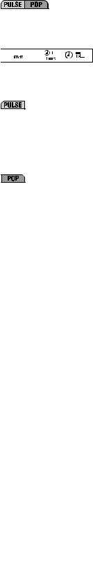
 Short arc “PRG 0”
Wählt man das manuelle Programm “PRG 0” mit Bi-Level-Funktion, können die Drahtgeschwindigkeit (mit Drehknopf (14), (LED 16c) aufleuchtend) und die tatsächliche Lichtbogenspannung des Sekundärschweißpegels I1 reguliert werden (mit Drehknopf (13)) (Einstellbereich 10-40) (LED (15a) aufleuchtend).
Im Modus MIG-MAG pulse arc können, wenn die Funktion Bi-level, pulse on pulse oder Tstart gewählt wird, der Strom I1 und IS (Istart)(mit Drehknopf (14)) und die Korrektur der synergistisch berechneten Lichtbogenlänge (mit Drehknopf (13)) des Sekundärschweißpegels reguliert werden (Einstellbereich -5% bis +5%) (LED (15c) aufleuchtend).
10c- 


 Short arc “PRG 0”
Im manuellen Modus “PRG 0” kann zur Optimierung der Lichtbogenzündung die Drahtgeschwindigkeit beim Start des Schweißvorgangs angepasst werden (Einstellung 1-100% und LED (15c) aufleuchtend).
Im Modus MIG-MAG Pulse arc 2-TAKT kann die Dauer des Anfangsstroms eingestellt werden (Tstart). Wird der Parameter auf null gesetzt, ist die Funktion ausgeschaltet,setztman ihnaufeinenbeliebigen Wertgrößeralsnull(Einstellung 0,1-3 Sekunden), kann die LED (10b) gewählt werden, um die Korrektur der Lichtbogenspannung und den Anfangsstromwert (Sekundärpegel) zu regulieren. Der Anfangsstrom kann höher oder niedriger als der Hauptschweißstrom eingestellt werden; ein höherer Anfangsstrom ist sehr zweckmäßig vor allem zum Schweißen von Aluminium und seinen Legierungen, weil das Werkstück schneller erhitzt wird (“Hot-start”).
Im Modus MIG-MAG Pulse on pulse kann die Dauer des Hauptschweißstroms reguliert werden (Einstellung 0,1-10 Sekunden und LED (15b) aufleuchtend).
10d- 

 Short arc “PRG 0”
Im manuellen Modus MIG-MAG “PRG 0” kann die elektronische Reaktanz reguliert werden (Einstellung 20-80% und LED (15c) aufleuchtend). Ein höherer Wert bedeutet ein heißeres Schweißbad. Im Bi-Level-Modus ist die elektronische Reaktanz für beide Pegel gleich.
Im Modus MIG-MAG pulse arc bestimmt dieser Parameter die Abschnürung des Lichtbogens. Je höher der Wert, desto konzentrierter ist der Lichtbogen während des Schweißens. In einem Schweißmodus mit zwei Strompegeln (Bi-Level, pulse on pulse oder Tstart) ist die Lichtbogenabschnürung für beide vorgegebenen Pegel gleich (+1% / -1%).
Im Modus MIG-MAG Pulse on pulse kann die Dauer des Sekundärschweißstroms eingestellt werden (Einstellung 0,1-10 Sekunden und LED (15b) aufleuchtend).
10e-
Nachbrennen des Drahtes bei Unterbrechung des Schweißvorgangs (Burn-back).
Einstellbar ist die Nachbrenndauer des Drahtes bei einer Unterbrechung der Schweißung.
Während der Erstellung eines Synergieprogramms MIG-MAG kann die Korrektur vorgegeben werden, die an der synergistisch berechneten BURN_BACK TIME vorgenommen werden soll (Einstellbereich -1% / +1% LED (15c) aufleuchtend).
 Short arc “PRG 0”
Bei sachgerechter Einstellung kann das Verkleben des Drahtes am Werkstück vermieden werden (Einstellung 0,001-1 Sekunden und LED (15b) aufleuchtend).
10f-
Post-gas
Gestattet die Anpassung der Schutzgasaustrittsdauer ab der Unterbrechung des Schweißvorgangs (Einstellung 0,1-10 Sekunden und LED (15b) aufleuchtend).
10g-
Abstiegsrampe des Schweißstroms (SLOPE DOWN).
Sie ist nur dann aktiviert, wenn die Synergieprogramme MIG-MAG Shortarc, Pulse arc und Pulse on Pulse benutzt werden.
Der Strom kann beim Loslassen des Brennerknopfes stufenweise zurückgeführt werden (Einstellung 0-3 Sekunden und LED (15b) aufleuchtend).
10h-
Punktschweißdauer (SPOT TIME).
Sie ist nur dann aktiviert, wenn der Modus “SPOT” mit der Taste (8) ausgewählt wird. Gestattet die Durchführung von MIG-MAG-Punktschweißungen mit Kontrolle der Schweißdauer (Einstellung 0,1-10 Sekunden und LED (15b) aufleuchtend).
11Taste für die manuelle Betätigung des elektrischen Gasventils.
Die Taste gestattet die Freigabe des Gasaustritts (Entlüftung der Leitungen - Einstellung des Durchsatzes), ohne den Brennerknopf benutzten zu müssen. Die Taste wird nicht dauerhaft betätigt.
12Taste für den manuellen Drahtvorschub.
Die Taste ermöglicht es, den Draht in der Führungsseele des Brenners vorzuschieben, ohne den Brennerknopf betätigen zu müssen; die Taste wird nicht dauerhaft betätigt, die Vorschubgeschwindigkeit ist unveränderlich.
13- Encoder-Drehknopf für die Einstellung der Schweißparameter (siehe 10a-10h).
14- Encoder-Drehknopf.
Mit dem Drehknopf werden geregelt:
-Der Schweißstrom I2 (LED (16a) aufleuchtend).
-Die Drahtvorschubgeschwindigkeit (LED (16c) aufleuchtend).
-Die Dicke des Schweißwerkstückes (LED (16b) aufleuchtend).
In einem Schweißmodus mit zwei Strompegeln (Bi-Level, pulse on pulse oder Tstart) können bei leuchtender LED (10b) mit dem Drehknopf geregelt werden:
- Der Schweißstrom I1 (LED (16a) aufleuchtend) des Sekundärpegels.
- Die Drahtvorschubgeschwindigkeit des Sekundärschweißpegels (LED (16c) aufleuchtend).
- Die Dicke des Schweißwerkstückes (LED (16b) aufleuchtend) auf dem Sekundärpegel.
15Alphanumerisches Display mit 3 Stellen. Hier werden angezeigt:
-der Wert der Schweißparameter (siehe (10a) bis (10h)) im Leerlaufbetrieb.
-die tatsächliche Lichtbogenspannung beim Schweißen.
ANMERKUNG: Bei der Unterbrechung des Schweißvorgangs wechselt das Display automatisch auf den Einstellwert.
- Alarmmeldungen (siehe Punkt 1).
15a, 15b, 15cLED für die Anzeige der benutzten Maßeinheit (Volt, Sekunden, Prozent).
16Alphanumerisches Display mit 3 Stellen. Hier werden ausgewiesen:
-der mit dem Encoder-Drehknopf (14) eingestellte Wert.
-der Iststrom beim Schweißen.
ANMERKUNG: Bei der Unterbrechung des Schweißvorgangs wechselt das Display automatisch auf den Einstellwert.
- Alarmmeldungen (siehe Punkt 1).
16a, 16b, 16cLED für die Anzeige der benutzten Maßeinheit (Strom in Ampere (A), Dicke in Millimetern (mm) und Drahtgeschwindigkeit in Metern pro Minute (m/min)).
17Taste für die Auswahl der Maßeinheit Ampere/Dicke in m/min (LED (16a) (16b) (16c)).
Bei den Synergieprogrammen MIG/MAG kann per Encoder (14) die zu schweißende Werkstückdicke, der Schweißstrom oder die Drahtgeschwindigkeit eingestellt werden.
Die Vorgabe jedes einzelnen Parameters (z. B. Werkstückdicke) definiert automatisch auch die übrigen Parameter (z. B. Schweißstrom und Drahtgeschwindigkeit).
Bei “PRG 0” manuelle Auswahl: Einstellbar ist nur die Drahtgeschwindigkeit (LED (16c) aufleuchtend).
4.3 AUFRUF UND SPEICHERUNG VON PROGRAMMEN
4.3.1 AUFRUF WERKSEITIG GESPEICHERTER PROGRAMME 4.3.1.1 Synergieprogramme MIG-MAG
Die Schweißmaschine hat Speicherplatz für 36 Synergieprogramme, deren Eigenschaften in der Tabelle (TAB.3) genannt sind. Diese Tabelle ist ausschlaggebend für die Auswahl eines Programmes, das sich für das gewünschte Schweißverfahren eignet.
Ein bestimmtes Programm wird durch wiederholtes Drücken der Taste “PRG” ausgewählt. Auf dem Display erscheinen die Programmnummern von “0” bis “36” (der Nummer “0” entspricht kein Synergieprogramm, sondern der Handbetrieb, wie er im folgenden Abschnitt beschrieben wird).
Anmerkung: Innerhalb eines Synergieprogrammes hat die Auswahl der gewünschten Übertragungsart Vorrang, also PULSE ARC oder SHORT/SPRAY ARC. Die Auswahl wird mit der zugehörigen Taste getroffen (siehe ABB. D (7)). Anmerkung: Alle nicht in der Tabelle genannten Drahttypen können im Handmodus “PRG 0” verwendet werden.
4.3.1.2 Betrieb im handmodus (“PRG 0”)
Der Handbetrieb entspricht der Ziffer “0” auf dem Display und ist nur dann aktiv, wenn zuvor die Übertragungsart SHORT/SPRAY ARC ausgewählt wurde (ABB. D (7)). In diesem Modus ist keine Synergie vorgesehen, alle Schweißparameter müssen deshalb vom Bediener manuell eingestellt werden.
Achtung! Sämtliche Parameter können frei eingestellt werden, die ihnen zugeordneten Werte sind deshalb unter Umständen für ein korrektes Schweißverfahren nicht geeignet.
Anmerkung: Es ist NICHT möglich, im Handmodus die Übertragungsart PULSE ARC zu benutzen.
4.3.2 SPEICHERUNG UND AUFRUF PERSONALISIERTER PROGRAMME IN MIGMAG
4.3.2.1 Einführung
Mit der Schweißmaschine lassen sich personalisierte Arbeitsprogramme mit einem PARAMETERSATZ (SET) speichern (SAVE), die für eine bestimmte Schweißung gelten. Jedes gespeicherte Programm kann jederzeit aufgerufen (RECALL) werden, sodaß der Schweißmaschinennutzer eine “betriebsbereite” Schweißmaschine für eine spezifische, zuvor optimierte Arbeit vorfindet.
4.3.2.2 Speicherplatz für individuell erstellte MIG-MAG-Programme
Die Schweißmaschine ermöglicht die Speicherung von 40 individuell erstellten Programmen für die drei synergistischen Übertragungsarten (SHORT/SPRAY ARC Pulse arc und Pulse on pulse) und den Betrieb im Handmodus. Es gelten folgende Daten:
-SHORT/SPRAY ARC SYNERGIE: 10 Programme speicherbar (verfügbare Nummern “1” bis “10”);
-SHORT/SPRAYARC MANUELL(“PRG=0”): 10 Programme speicherbar (verfügbare Nummern “1” bis “10”);
-PULSE ARC SYNERGIE: 10 Programme speicherbar (verfügbare Nummern “1” bis “10”);
-PULSE ARC SYNERGIE PULSE ON PULSE: 10 Programme speicherbar (verfügbare Nummern “1” bis “10”).
ANMERKUNG: Das gewünschte Programm wird wie folgt aufgerufen:
a)Die gewünschte Übertragungsart auswählen: PULSE ARC, PULSE ARC PULSE-ON- PULSE oder SHORT/SPRAY ARC oder “PRG=0” wählen, falls Programme im Handmodus bereits gespeichert sind;
b)Die Programmnummer wählen (wie in Abschnitt 4.3.1 beschrieben).
4.3.2.3 Vorgehensweise für die Speicherung (SAVE).
Nachdem die Schweißmaschine für einen bestimmten Schweißvorgang optimal eingestellt wurde, gehen Sie folgendermaßen vor (siehe ABB. D):
a)Taste (5) “SAVE” drücken.
b)Auf dem Display (16) erscheint “Pr”, auf dem Display (15) eine Nummer (zwischen “1” und “10”).
c)Durch Drehen am Encoderregler (egal ob (13) oder (14)) wird die Nummer gewählt, unter der das Programm gespeichert werden soll (siehe auch 4.3.2 ).
d)Erneut die Taste “SAVE” drücken.
e)Die Displays (15) und (16) blinken.
f)Innerhalb von zwei Sekunden nochmals die Taste “SAVE” drücken.
g)Auf den Displays erscheint “St Pr”, das Programm wurde also gespeichert; nach 2 Sekunden schalten die Displays automatisch auf die Werte der soeben
- 29 -
gespeicherten Parameter um.
Anmerkung. Wenn die Displays blinken und die Taste “SAVE” nicht noch einmal innerhalb von 2 Sekunden gedrückt wird, erscheint auf den Displays “No St”, und das Programm wird nicht gespeichert; die Displays kehren automatisch zur ursprünglichen Anzeige zurück.
4.3.2.4 Vorgehensweise für den Aufruf eines personalisierten Programmes (RECALL)
Vor dem Aufrufen eines Programmes ist zu prüfen, ob die ausgewählte Übergangsart (PULSE ARC, PULSE ARC PULSE-ON-PULSE, SHORT/SPRY ARC oder “PRG=0”) tatsächlich diejenige ist, mit der gearbeitet werden soll.
Anschließend wie folgt vorgehen (siehe ABB. D):
a)Die Taste “RECALL” drücken.
b)Auf dem Display (16) erscheint “Pr”, auf dem Display (15) eine Nummer (zwischen “1” und “10”).
c)Durch Drehen des Encoderreglers (egal ob (13) oder (14)) wird die Nummer ausgewählt, unter der das gewünschte Programm abgespeichert wurde.
d)Erneut die Taste “RECALL” für länger als 2 Sekunden drücken.
e)Auf den Displays erscheint “Ld Pr”, das Programm wurde somit aufgerufen; die Displays schalten automatisch nach 2 Sekunden auf die Werte des soeben aufgerufenen Programmes um.
Anmerkung. Wenn die Taste “RECALL” nicht noch einmal länger als 2 Sekunden gedrückt wird, ist auf den Displays “No Ld” zu erkennen und das Programm wird nicht geladen; die Displays kehren automatisch zur Ursprungsanzeige zurück.
ANMERKUNGEN:
-WÄHREND DER BENUTZUNG DER TASTEN “SAVE” UND “RECALL” LEUCHTET DIE LED “PRG” AUF.
-EIN AUFGERUFENES PROGRAMM KANN VOM SCHWEISSENDEN NACH BELIEBEN VERÄNDERT WERDEN, ABER DIE GEÄNDERTEN WERTE WERDEN NICHT AUTOMATISCH GESPEICHERT. SOLLEN DIE NEUEN WERTE IM SELBEN PROGRAMM GESPEICHERT WERDEN, MUSS SO VORGEGANGEN WERDEN, WIE ES FÜR DIE SPEICHERUNG BESCHRIEBEN WURDE (siehe 4.3.2.3).
-DIE REGISTRIERUNG DER PERSONALISIERTEN PROGRAMME UND DIE ABLAUFPLANUNG DER ZUGEHÖRIGEN PARAMETER IST SACHE DES NUTZERS.
-IN DEN BETRIEBSARTEN ELEKTRODE MMA ODER WIG KÖNNEN KEINE PERSONALISIERTEN PROGRAMME GESPEICHERT WERDEN.
5.INSTALLATION
VORSICHT! VOR BEGINN ALLER ARBEITEN ZUR INSTALLATION UND ZUM ANSCHLUSS AN DIE STROMVERSORGUNG MUSS DIE SCHWEISSMASCHINE UNBEDINGT AUSGESCHALTET UND VOM
STROMNETZ GETRENNT WERDEN.
DIE STROMANSCHLÜSSE DÜRFEN AUSSCHLIESSLICH VON FACHKUNDIGEM PERSONAL DURCHGEFÜHRT WERDEN.
5.1 AUFBAU
-Den Wagen von der Verpackung befreien und nach der beiliegenden Anleitung montieren.
-Die Schweißmaschine, die Drahtzufuhreinrichtung und, falls vorhanden, das Kühlaggregat von der Verpackung befreien und auf den Wagen installieren.
ANMERKUNG: Den polarisierungsstecker einfügen, wenn kein Kühlaggregat GRA angeschlossen wird (ABB. E).
5.2ANHEBEN DER SCHWEISSMASCHINE ODER DER SCHWEISSAUSRÜSTUNG
-Die Schweißmaschine muss angehoben werden, wie in der Abbildung (ABB. O) dargestellt, und zwar ohne abnehmbare Teile (Brenner, Gasschläuche, Kabel etc.), die sich lösen könnten.
Die Befestigungsringe wie in der Abbildung gezeigt anordnen und mit den beiden als Zubehör enthaltenen Schrauben M8x25 montieren.
Achtung: Die Hebeösen mit Gewindebohrung M8 sind nicht im Lieferumfang enthalten.
-Die Schweißausrüstung muss, wie in der Abbildung (ABB. P) dargestellt; ohne abnehmbare Teile (Drahtzufuhreinrichtung, Flasche, Kabel, Fernbedienung) angehoben werden, die sich lösen könnten.
Achtung: Verwenden Sie gleichzeitig die 4 entsprechend eingerichteten Hebestellen.
5.3 LAGE DER SCHWEISSMASCHINE
Suchen Sie den Installationsort der Schweißmaschine so aus, daß der Einund Austritt der Kühlluft nicht behindert wird (Zwangsumwälzung mit Ventilator, falls vorhanden); stellen Sie gleichzeitig sicher, daß keine leitenden Stäube, korrosiven Dämpfe, Feuchtigkeit u. a. angesaugt werden.
Um die Schweißmaschine herum müssen mindestens 250mm Platz frei bleiben.
VORSICHT! Die Schweißmaschine ist auf einer flachen, ausreichend tragfähigen Oberfläche aufzustellen, um das Umkippen und Verschieben der Maschine zu verhindern.
5.4 NETZANSCHLUSS 5.4.1 Hinweise
Bevor die elektrischen Anschlüsse hergestellt werden, ist zu prüfen, ob die Daten auf dem Typenschild der Schweißmaschine mit der Netzspannung und Frequenz am Installationsort übereinstimmen.
Die Schweißmaschine darf ausschließlich mit einem Speisesystem verbunden werden, das einen geerdeten Nulleiter hat.
Zum Schutz vor indirektem Kontakt müssen folgende Differenzialschaltertypen benutzt werden:
-Typ A ( 

 ) für einphasige Maschinen;
-Typ B ( 


 ) für dreiphasige Maschinen.
Um den Anforderungen der Norm EN 61000-3-11 (Flicker) gerecht zu werden, empfiehlt es sich, die Schweißmaschinen an den Schnittstellen des Versorgungsnetzes anzuschließen, die eine Impedanz von unter Zmax = 0.283ohm.
-Die Schweißmaschine genügt nicht den Anforderungen der Norm IEC/EN 61000-3-12. Wenn sie an ein öffentliches Versorgungsnetz angeschlossen wird, hat der Installierende oder der Betreiber pflichtgemäß unter seiner Verantwortung zu prüfen, ob die Schweißmaschine angeschlossen werden darf (falls erforderlich, ziehen Sie den Betreiber des Verteilernetzes zurate).
5.4.2Stecker und Buchse
Verbinden Sie mit dem Versorgungskabel einen Normstecker (3P + T) mit ausreichender Stromfestigkeit und richten Sie eine Netzdose mit Schmelzsicherungen oder Leistungsschalterein. Der zugehörige Erdungsanschluß muß mit dem Schutzleiter (gelb-grün) der Versorgungsleitung verbunden werden.
In Tabelle (TAB.1) sind die empfohlenenAmperewerte der trägen Leitungssicherungen aufgeführt, die auszuwählen sind nach dem von der Schweißmaschine abgegebenen max. Nennstrom und der Versorgungsnennspannung.
5.5. ANSCHLÜSSE DES SCHWEISSSTROMKREISES
VORSICHT!BEVORDIEFOLGENDENANSCHLÜSSEVORGENOMMEN WERDEN, IST SICHERZUSTELLEN, DASS DIE SCHWEISSMASCHINE AUSGESCHALTET UND VOM VERSORGUNGSNETZ GENOMMEN IST.
In der Tabelle (TAB. 1) ist der empfohlene Wert für die Schweißkabel aufgeführt (in mm2)
5.5.1 DRAHTSCHWEISSVERFAHREN MIG-MAG (ABB. F) 5.5.1.1 Anschluss der Gasflasche
-Den Druckverminderer auf das Ventil der Glasflasche schrauben. Bei Verwendung von Argon oder einem Ar/CO2 –Gemisch wird das als Zubehör mitgelieferte Reduzierstück zwischengeschraubt.
-Den Gaszufuhrschlauch an den Reduzierer anschließen und die mitgelieferte Schlauchschelle festziehen; dann das andere Schlauchende an das zugehörige Verbindungsstück auf der Rückseite der Schweißmaschine anschließen und mit der im Lieferumfang enthaltenen Schelle befestigen.
-Den Einstellring des Druckverminderers vor dem Öffnen des Flaschenventils lockern.
5.5.1.2Anschluss des Brenners
-Den Brenner in seine Aufnahmevorrichtung stecken und den Feststellring von Hand fest anziehen.
-Den Brenner durch das Abnehmen der Düse und des Kontaktröhrchens auf die erstmalige Drahtzuführung vorbereiten, denn in diesem Zustand tritt der Draht leichter aus.
-Schweißstromkabel an den Schnellanschluss (+) legen.
-Steuerkabel an den zugehörigen Steckanschluss legen.
-In den Ausführungen mit wassergekühltem Brenner die Wasserleitungen an die Schnellverbindungen legen.
-Um Überhitzungen und Leistungsverluste zu vermeiden, achten Sie darauf, dass die Steckverbindungen fest sitzen.
-Den Gaszufuhrschlauch an den Reduzierer anschließen und die mitgelieferte Schelle festziehen; dann das andere Schlauchende an das Verbindungsstück auf der Rückseite der Schweißmaschine anschließen und mit der im Lieferumfang enthaltenen Schelle fixieren.
5.5.1.3Anschluß Schweißstrom-Rückleitungskabel
-Es wird mit dem Werkstück oder der Metallbank verbunden, auf dem es aufliegt, und zwar so nah wie möglich an der Schweißnaht.
-Dieses Kabel ist an die Klemme mit dem Symbol (-) anzuschließen.
5.5.2 WIG-SCHWEISSEN (ABB.G) 5.5.2.1 Verbindung mit der Gasflasche
-Druckverminderer an das Ventil der Gasflasche schrauben. Dazwischen wird das Reduzierstück gesetzt, das als Zubehör geliefert wird, wenn Argon oder Gemische aus Argon/CO2 verwendet werden.
-Gaszufuhrschlauch an den Druckverminderer anschließen und die mitgelieferte Schlauchschelle festziehen; dann das andere Ende des Schlauches an der zugehörigen Verbindungsstelle auf der Rückseite der Schweißmaschine anschließen und mit der beiliegenden Schelle befestigen.
-Den Einstellring des Druckverminderers lockern, bevor das Flaschenventil geöffnet wird.
5.5.2.2 Anschluß Schweißstrom-Rückleitungskabel
-Es wird mit dem Werkstück oder der Metallbank verbunden, auf dem es aufliegt, und zwar so nah wie möglich an der Schweißnaht.
-Dieses Kabel ist an die Klemme mit dem Symbol (+) anzuschließen.
5.5.2.3 Anschluß des Brenners
-Verbinden Si den WIG-Brenner mit dem Schnellanschluß (-) auf der vorderen Tafel der Schweißmaschine; schließen die Gasleitung und das Steuerkabel für den Brenner an.
5.5.3 SCHWEISSEN MIT UMHÜLLTER ELEKTRODE MMA (ABB. H) 5.5.3.1 Anschluss der Elektrodenklemme
Nahezu sämtliche Arten von umhüllten Elektroden müssen an den Pluspol (+) des Generators angelegt werden, nur sauer umhüllte Elektroden werden mit dem Minuspol (-) verbunden.
Das Kabel der Elektrodenklemme an den Schnellanschluss (+) auf dem vorderen Bedienfeld anschließen.
Anmerkung: In einigen Fällen wird für die Elektrodenklemme der Minuspol (-) empfohlen, prüfen Sie deshalb die Angaben des Elektrodenherstellers.
5.5.3.2 Anschluß Schweißstrom-Rückleitungskabel
-Es wird mit dem Werkstück oder der Metallbank verbunden, auf dem es aufliegt, und zwar so nah wie möglich an der Schweißnaht.
-Dieses Kabel ist an die Klemme mit dem Symbol (-) anzuschließen.
5.5.4 EMPFEHLUNGEN
-Drehen Sie die Stecker der Schweißkabel so tief es geht in die Schnellanschlüsse, damit ein einwandfreier elektrischer Kontakt sichergestellt ist; andernfalls überhitzen sich die Stecker, verschleißen vorzeitig und büßen an Wirkung ein.
-Verwenden Sie möglichst kurze Schweißkabel.
-Vermeiden Sie es, anstelle des Schweißstrom-Rückleitungskabels metallische
Strukturen zu verwenden, die nicht zum Werkstück gehören; dadurch wird die Sicherheit beeinträchtigt und möglicherweise nicht zufriedenstellende Schweißergebnisse hervorgebracht.
5.6 EINLEGEN DER DRAHTSPULE (ABB. I)
VORSICHT! BEVOR MIT DER ZUFÜHRUNG DES DRAHTES BEGONNEN WIRD, MUSS SICHERGESTELLT SEIN, DASS DIE SCHWEISSMASCHINE AUSGESCHALTET UND VOM
VERSORGUNGSNETZ GETRENNT IST.
PRÜFEN SIE, OB DIE DRAHTFÖRDERROLLEN, DIE DRAHTFÜHRUNGSSEELE UND DAS KONTAKTROHR DES BRENNERS MIT DEM DURCHMESSER UND DER ART DES VORGESEHENEN KABELS KOMPATIBEL UND KORREKT ANGEBRACHT SIND. WÄHREND DER DRAHT EINGEFÄDELT WIRD, DÜRFEN KEINE SCHUTZHANDSCHUHE GETRAGEN WERDEN.
-Das Haspelfach öffnen.
-Drahtspule auf die Haspel setzen, das Drahtende dabei nach oben gerichtet. Der Mitnahmestift der Haspel muß dabei korrekt in der dafür vorgesehenen Öffnung sitzen (1a).
-Nun die Andrück-Gegenrolle(n) lösen und von der / den unteren Rolle(n) entfernen
- 30 -
 Loading...