

Page 1

xx
TDS1000 & TDS2000 Series
Digital Storage Oscilloscopes
Operator Training Kit Manual
*P071115101*
071-1151-01
1100111001010
0110011
11
11
001
11011
010100101101
1110110111
0101011
01010
Page 2

Page 3

TDS1000 & TDS2000 Series
Oscilloscopes
Operator Training Kit Manual
071-1151-01
www.tektronix.com
Page 4

This product training document file is protected by Copyright © Tektronix,
Inc. All rights reserved.
End users of this Tektronix product training document file are permitted to
print any portion of this file or copy the electronic file for personal use. Print
or electronic reproduction of this product training document file for resale is
strictly prohibited.
Tektronix, Inc., P.O. Box 500, Beaverton, OR 97077
TEKTRONIX and TEK a re registered trademarks of Tektronix, Inc.
Page 5

WARRANTY
Tektronix warrants that the parts, assemblies and supplies (“products”) that it manufactures
and sells will be free from defects in materials and workmanship for a period of three (3)
months from the date of shipment. If a product proves defective during this warranty
period, Tektronix, at its option, either will repair the defective product without charge for
parts and labor, or will provide a replacement in exchange for the defective product.
In order to obtain service under this warranty, Customer must notify Tektronix of the defect
before the expiration of the warranty period and make suitable arrangements for the
performance of service. Customer shall be responsible for packaging and shipping the
defective product to the service center designated by Tektronix, with shipping charges
prepaid. Tektronix shall pay for the return of the product to Customer if the shipment is to
a location within the country in which the Tektronix service center is located. Customer
shall be responsible for paying all shipping charges, duties, taxes, and any other charges for
products returned to any other locations.
This warranty shall not apply to any defect, failure or damage caused by improper use or
improper or inadequate maintenance and care. Tektronix shall not be obligated to furnish
service under this warranty a) to repair damage resulting from attempts by personnel other
than Tektronix representatives to install, repair or service the product; b) to repair damage
resulting from improper use or connection to incompatible equipment; c) to repair any
damage or malfunction caused by the use of non-Tektronix supplies; or d) to service a
product that has been modified or integrated with other products when the effect of such
modification or integration increases the time or difficulty of servicing the product.
THIS WARRANTY IS GIVEN BY TEKTRONIX IN LIEU OF ANY OTHER
WARRANTIES, EXPRESS OR IMPLIED. TEKTRONIX AND ITS VENDORS
DISCLAIM ANY IMPLIED WARRANTIES OF MERCHANTABILITY OR
FITNESS FOR A PARTICULAR PURPOSE. TEKTRONIX’ RESPONSIBILITY
TO REPAIR OR REPLACE DEFECTIVE PRODUCTS IS THE SOLE AND
EXCLUSIVE REMEDY PROVIDED TO THE CUSTOMER FOR BREACH OF
THIS WARRANTY. TEKTRONIX AND ITS VENDORS WILL NOT BE LIABLE
FOR ANY INDIRECT, SPECIAL, INCIDENTAL, OR CONSEQUENTIAL
DAMAGES IRRESPECTIVE OF WHETHER TEKTRONIX OR THE VENDOR
HAS ADVANCE NOTICE OF THE POSSIBILITY OF SUCH DAMAGES.
Page 6

Page 7

General Safety Summary
Review the following safety precautions to avoid injury and prevent
damage to this product or any products connected to it. To avoid
potential hazards, use this product only as specified.
While using this product, you may need to access other parts of the
system. Read the General Safety Summary in other system manuals
for warnings and cautions related to operating the system.
To Avoid Fire or Personal Injury
Connect and Disconnect Properly. Do not connect or disconnect probes
or test leads while they are connected to a voltage source.
Connect the ground lead of the probe to earth ground only.
Replace Batteries Properly. Replace batteries only with the proper type
and rating specified.
Use Proper AC Adapter. Use only the AC adapter specified for this
product.
Use Proper Fuse. Use only the fuse type and rating specified for this
product.
Avoid Exposed Circuitry. Do not touch exposed connections and
components when power is present.
Do Not Operate With Suspected Failures. If you suspect there is damage
to this product, have it inspected by qualified service personnel.
Do Not Operate in Wet/Damp Conditions.
Do Not Operate in an Explosive Atmosphere.
Keep Product Surfaces C lean and Dry.
TDS1000 and TDS2000B Series Oscilloscopes -- Operator Training Kit
Page 8
General Safety Summary
Safety Terms and Symbols
Terms in This Manual. These terms may appear in this manual:
WARNING. Warning statements identify conditions or practices that
could result in injury or loss of life.
CAUTION. Caution statements identify conditions or practices that
could result in damage to this product or other property.
Terms on the Product. These terms may appear on the product:
DANGER indicates an injury hazard immediately accessible as you
read the marking.
WARNING indicates an injury hazard not immediately accessible as
you read the marking.
CAUTION indicates a hazard to property including the product.
Symbols on the Product. These symbols may appear on the product:
CAUTION
Refer to Manual
Standby
TDS1000 and TDS2000B Series Oscilloscopes -- Operator Training Kit
Page 9

Contacting Tektronix
Phone 1-800-833-9200*
Address Tektronix, Inc.
Department or name (if known)
14200 SW Karl Braun Drive
P.O. Box 500
Beaverton, OR 97077
USA
Web site www.tektronix.com
Sales
support
Service
support
Technical
support
* This phone number is toll free in North America. After office
hours, please leave a voice mail message.
Outside North America, contact a Tektronix sales office or
distributor; see the Tektronix web site for a list of offices.
TDS1000 and TDS2000B Series Oscilloscopes -- Operator Training Kit
1-800-833-9200, select option 1*
1-800-833-9200, select option 2*
Email: techsupport@tektronix.com
1-800-833-9200, select option 3*
6:00 a.m. -- 5:00 p.m. Pacific time
Page 10

Contacting Tektronix
TDS1000 and TDS2000B Series Oscilloscopes -- Operator Training Kit
Page 11

Table of Contents
Introduction to Oscilloscopes and Probes.................................1-1
Getting to Know Oscilloscopes............................................ 1-2
Introduction to Oscilloscopes........................................... 1-2
Types of Oscilloscopes.................................................... 1-5
Oscilloscope Terminology ............................................. 1-14
Getting to Know Probes..................................................... 1-23
Introduction to Probes ................................................... 1-23
Types of Voltage Probes............................................... 1-24
How Probes Affect Measurements................................ 1-27
Summary.................................................................................1-31
Getting Started with the TDS1000 and TDS2000 Series
Oscilloscopes ............................................................................2-1
Introduction to TDS1000 and TDS2000 Series Oscilloscopes
............................................................................................. 2-3
Features of the TDS1000 and TDS2000 Series
Oscilloscopes................................................................... 2-6
Safety Precautions ........................................................ 2-11
Preliminary Functional Check........................................ 2-13
Introduction to the Training 1 Signal Board...................2-16
probe compensation...................................................... 2-20
Primary Controls ................................................................ 2-25
VERTICAL Controls....................................................... 2-26
HORIZONTAL Controls................................................. 2-37
TRIGGER Controls........................................................2-42
Menu Function Controls ................................................ 2-56
TDS1000 and TDS2000 Series Oscilloscopes – Operator Training Kit i
Page 12

Enhanced Features............................................................ 2-77
Help ............................................................................... 2-77
Autoset Feature............................................................. 2-88
DEFAULT SETUP Feature............................................2-96
SINGLE SEQ Feature ................................................... 2-96
Print Feature..................................................................2-97
Using VERTICAL Controls ........................................................3-1
VERTICAL Controls............................................................. 3-2
Setting Up VERTICAL Controls....................................... 3-4
Switching the Input Coupling...........................................3-6
VERTICAL Control MENU Buttons.................................... 3-12
Modifying the Vertical Scale of a Displayed Waveform. 3-12
MATH MENU Controls....................................................... 3-14
Adding Two Waveforms ................................................ 3-14
Subtracting Two Waveforms ......................................... 3-17
Performing FFT Operations........................................... 3-20
Summary.................................................................................3-23
Using HORIZONTAL Controls ..................................................4-1
HORIZONTAL Controls ....................................................... 4-2
Setting Up the HORIZONTAL Controls........................... 4-3
Setting the Delay Time for a Waveform .......................... 4-5
HORIZONTAL Control MENU Button..................................4-8
Expanding the Waveform Display ................................... 4-8
Summary.................................................................................4-13
ii TDS1000 and TDS2000 Series Oscilloscopes – Operator Training Kit
Page 13

Using TRIGGER Controls .........................................................5-1
Trigger Controls ................................................................... 5-2
TRIGGER MENU Controls................................................... 5-4
Selecting a Trigger Type ................................................. 5-4
Selecting the Signal Coupling for a Trigger..................... 5-7
Using an External Trigger.............................................. 5-11
Triggering on a specific pulse width .............................. 5-16
Capturing a Single-shot Sig nal...................................... 5-21
Trigger Holdoff Controls.....................................................5-27
Assigning Trigger Holdoff to a Pseudo Random Signal 5-28
Assigning Trigger Holdoff to an AM Signal.................... 5-30
Summary.................................................................................5-35
Using Menu Function Controls..................................................6-1
MENU Function Controls ..................................................... 6-3
ACQUIRE Menu Function Controls ..................................... 6-5
Using the Peak Detect Acquisition Mode ........................ 6-7
Using the Average Acquisition Mode ............................ 6-11
DISPLAY Menu Function Controls .................................... 6-14
Selecting the Display Type............................................ 6-14
Using Persistence.......................................................... 6-18
Using the XY Display Mode........................................... 6-21
Measuring the Vertical Scale......................................... 6-24
Measuring the Horizontal Scale..................................... 6-27
Measuring Pulse Width.................................................. 6-29
Measuring Rise Time..................................................... 6-32
TDS1000 and TDS2000 Series Oscilloscopes – Operator Training Kit iii
Page 14

MEASURE Menu Function Contro ls..................................6-36
Taking Automatic Measurements..................................6-36
SAVE/RECALL Menu Function Controls........................... 6-42
Saving and Recalling a Setup ....................................... 6-42
Saving and Recalling a Waveform ................................ 6-47
UTILITY Menu Function Controls ...................................... 6-50
Displaying the System Status........................................ 6-50
Summary.................................................................................6-53
Appendix A: Training 1 Signal Board: Signal Definitions……...A-1
Appendix B: Glossary……………………………………………..B-1
iv TDS1000 and TDS2000 Series Oscilloscopes – Operator Training Kit
Page 15
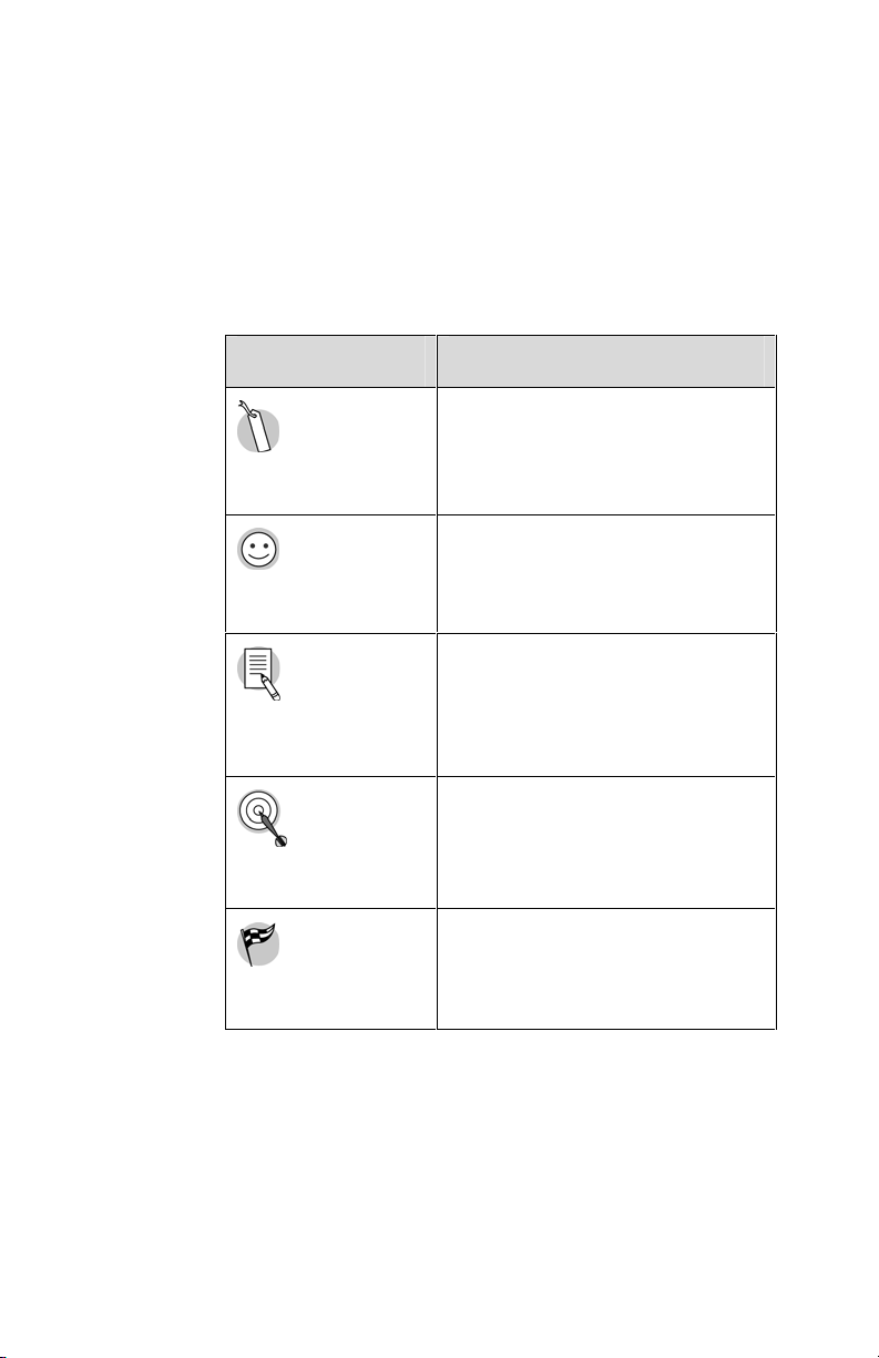
Symbols
Here is a list of symbols used in this Operator Training
Kit. These symbols will help you navigate faster and
access specific types of information quickly.
Icon Description
Cross Reference
Placed next to text that
provides a link to details of the
topic being referred.
Ease of Use
Note
Objective
Procedure Start
Placed next to text that explains
how a feature makes the
oscilloscope easier to use.
Placed next to text that
provides an important piece of
information regarding a
procedure or feature.
Placed next to text that lists the
objectives for the lessons.
Placed next to text that
introduces a procedure.
TDS1000 and TDS2000 Series Oscilloscopes – Operator Training Kit v
Page 16

vi TDS1000 and TDS2000 Series Oscilloscopes – Operator Training Kit
Page 17

TDS1000 and TDS2000 Series Oscilloscopes – Operator Training Kit 1-1
1
Introduction to Oscilloscopes and Probes
The environment around us contains various energy
sources, such as electronic appliances, which generate
signals. Oscilloscopes allow you to observe these
signals to analyze the performance of their energy
sources. This module introduces you to oscilloscopes
and the methods to measure electrical signals by using
oscilloscopes and associated probes.
At the end of this module, you will be able to:
• Identify the types of oscilloscopes.
• List the terms to describe the performance of
oscilloscopes.
Probes
Introduction to Oscilloscopes and
1
• Identify the types of voltage probes.
• Describe the loading effects of probes on signals.
TDS1000 and TDS2000 Series Oscilloscopes – Operator Training Kit 1-1
Page 18

1
Introduction to Oscilloscopes and Probes
Getting to Know Oscilloscopes
This section introduces you to oscilloscopes and
describes the different types of oscilloscopes and their
functions. The section includes the following topics:
• Introduction to Oscilloscopes
• Types of Oscilloscopes
• Oscilloscope Terminology
Introduction to Oscilloscopes
You use an oscilloscope to display electrical signals as
waveforms. A waveform is a graphical representation of
a wave.
An oscilloscope receives an electrical signal and
converts it into a waveform. The waveform shows the
change in voltage with time on the oscilloscope display
screen.
1-2 TDS1000 and TDS2000 Series Oscilloscopes – Operator Training Kit
Page 19

1
Introduction to Oscilloscopes and Probes
You can use an oscilloscope to determine the following:
• The frequency of an oscillating signal
• The malfunctioning com ponent in an electrical circuit
• Whether the signal is direct current (DC) or
alternating current (AC)
• What part of the signal is noise
You can also use oscilloscopes to measure electrical
signals in response to physical stimuli, such as sound,
mechanical stress, pressure, light, or heat. For example,
a television technician can use an oscilloscope to
measure signals from a television circuit board while a
medical researcher can use an oscilloscope to measure
brain waves.
TDS1000 and TDS2000 Series Oscilloscopes – Operator Training Kit 1-3
Page 20

1
Introduction to Oscilloscopes and Probes
An oscilloscope contains various controls that help you
analyze waveforms displayed on a graphical grid called
a graticule. The vertical or Y-axis of the graticule
typically represents voltage while the horizontal or X-axis
typically represents time.
Figure 1.1 shows how an oscilloscope displays voltage
and time.
Figure 1.1: Oscilloscope display
1-4 TDS1000 and TDS2000 Series Oscilloscopes – Operator Training Kit
Page 21
Types of Oscilloscopes
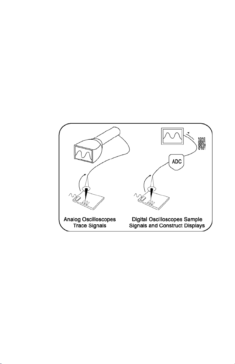
Electronic equipment can be categorized into two types,
analog and digital. Analog equipment use variable
voltages while digital equipment use binary numbers that
represent voltage sam ples .
categorized into analog and digital.
Figure 1.2 shows an analog and a digital oscilloscope.
1
Introduction to Oscilloscopes and Probes
Similarly, oscill os copes are
Figure 1.2: Analog and digital oscilloscopes
TDS1000 and TDS2000 Series Oscilloscopes – Operator Training Kit 1-5
Page 22
1
Introduction to Oscilloscopes and Probes
Analog Oscilloscopes
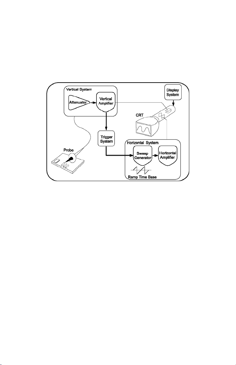
Let us look at how analog oscilloscopes work. Figure 1.3
shows a block diagram of an analog oscilloscope.
Figure 1.3: Block diagram of an analog oscilloscope
When you connect an analog oscilloscope to a circuit,
the voltage signal from the circuit travels to the vertical
deflection plates of the oscilloscope screen, which is a
phosphor-coated cathode-ray tube (CRT). As a result,
when an electron beam strikes the phosphor coating of
the CRT, a glowing dot appears. When you apply
voltage to the deflection plates, the glowing dot moves.
1-6 TDS1000 and TDS2000 Series Oscilloscopes – Operator Training Kit
Page 23
1
Introduction to Oscilloscopes and Probes
A positive voltage causes the dot to move up while a
negative voltage causes the dot to move down. The
signal also travels to a trigger system, which initiates a
horizontal sweep. The trigger causes the time base on
the X-axis of the display grid to move the glowing dot
from left to right across the screen within a specified time
interval. When many sweeps occur in a rapid sequence,
the movements of the glowing dot blend into a solid line.
Together, the horizontal sweeping and vertical deflecting
actions are displayed as a signal graph on the screen.
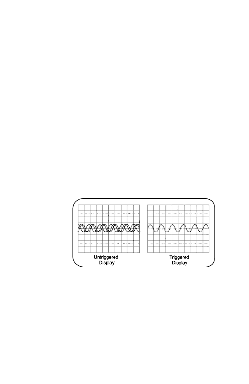
You use triggering to stabilize a repeating signal. Proper
triggering ensures that the sweep begins at the same
point of a repeating signal so that a stable waveform is
visible.
Figure 1.4 shows untriggered and triggered waveforms.
Figure 1.4: Untriggered and triggered display
TDS1000 and TDS2000 Series Oscilloscopes – Operator Training Kit 1-7
Page 24

1
Introduction to Oscilloscopes and Probes
In analog oscilloscopes, the CRT limits the range of sine
wave frequencies that the oscilloscope can display. At
low frequencies, the signal appears as a bright, slowmoving dot that does not display the waveform. When
signal frequencies exceed the display speed of the CRT,
the displayed signal is distorted, attenuated, or both.
You can use an analog oscilloscope to display rapidly
varying signals in real time. The phosphor-based display
of an analog oscilloscope has an intensity grading
feature, which makes the trace appear brighter where
the signal features occur most frequently. You can then
distinguish between signal details by observing the
intensity levels of the displayed waveform.
1-8 TDS1000 and TDS2000 Series Oscilloscopes – Operator Training Kit
Page 25

Digital Oscilloscopes
In contrast to analog oscilloscopes, digital oscilloscopes
use an analog-to-digital converter (ADC). An ADC
converts the voltage being measured into a digital
format. A digital oscilloscope acquires a waveform as a
series of signal samples, which are stored in its memory
and then reassembled for viewing on the screen.
Digital oscilloscopes are categorized into two types,
digital storage oscilloscopes (DSO) and digital phosphor
oscilloscopes (DPO). Let us look at how these two types
of digital oscilloscopes work.
1
Introduction to Oscilloscopes and Probes
TDS1000 and TDS2000 Series Oscilloscopes – Operator Training Kit 1-9
Page 26

1
Introduction to Oscilloscopes and Probes
Digital Storage Oscilloscopes
In a DSO, an ADC takes samples of a signal at discrete
points in time and converts the voltage at these points to
digital values called sample points. The DSO contains a
sample clock that determines the frequency at which the
ADC takes samples. The rate at which the ADC takes
samples is called the sample rate and is measured in
samples per second.
The sample points from the ADC are stored in the
memory as waveform points. These waveform points
make one waveform record. The number of waveform
points used to make a waveform record is called the
record length. A waveform is then displayed on the
screen.
1-10 TDS1000 and TDS2000 Series Oscilloscopes – Operator Training Kit
Page 27
1
Introduction to Oscilloscopes and Probes
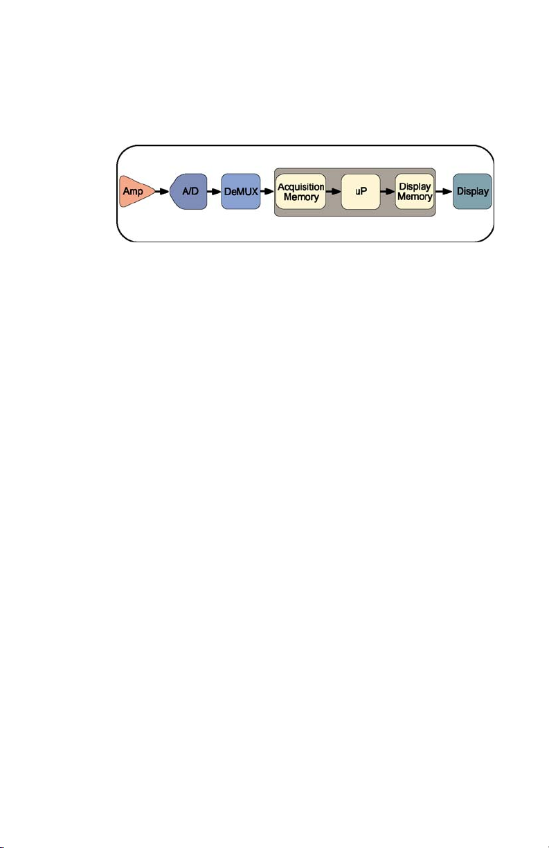
Figure 1.5 shows the block diagram of a DSO.
Figure 1.5: Block diagram of a DSO
A DSO contains a microprocessor (represented by uP in
the figure above) that processes the signal, manages
display activities, and interprets front panel controls.
TDS1000 and TDS2000 Series Oscilloscopes – Operator Training Kit 1-11
Page 28

1
Introduction to Oscilloscopes and Probes
Digital Phosphor Oscilloscopes
A DPO uses electronic Digital Phosphor to display
waveforms on the screen. Digital Phosphor is a
database that uses separate cells to store information
corresponding to each pixel of the oscilloscope display
screen. Every time a waveform triggers, the cells that
map to the display path of the waveform are updated
with intensity inform ation. In tensi t y infor mation increases
in cells through which the waveform passes.
When the Digital Phosphor database is loaded on the
display screen of the oscilloscope, the screen shows
intensified waveform areas, in proportion to the
frequency of occurrence of the signal at each point. A
DPO may also allow varying fr equency of signal details
to be displayed in different colors.
1-12 TDS1000 and TDS2000 Series Oscilloscopes – Operator Training Kit
Page 29
1
Introduction to Oscilloscopes and Probes
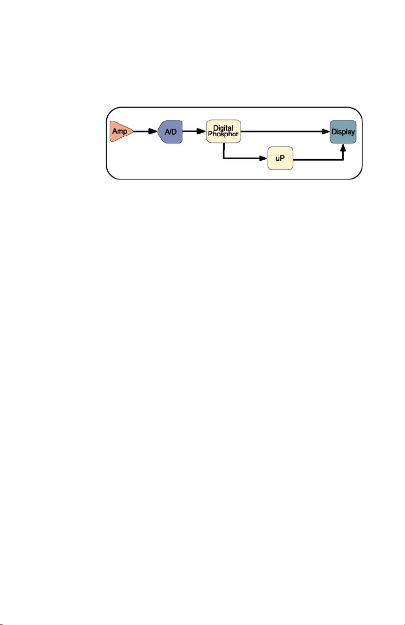
Figure 1.6 shows how a DPO works.
Figure 1.6: Block diagram of DPO
Similar to a DSO, a DPO also uses a microprocessor for
display management, measurement automation, and
analysis of the displayed waveforms.
TDS1000 and TDS2000 Series Oscilloscopes – Operator Training Kit 1-13
Page 30

1
Introduction to Oscilloscopes and Probes
Oscilloscope Terminology
This topic discusses the terminology related to the
following categories:
• Types of waves
• Waveform measurements
• Performance terms
Types of Waves
You use waveform shapes to analyze a signal. Different
types of waveforms represent different types of signals.
Waveforms are classified into the following groups:
• Sine waves
• Square and rectangular waves
• Step and pulse waves
• Sawtooth and triangle waves
• Complex waves
1-14 TDS1000 and TDS2000 Series Oscilloscopes – Operator Training Kit
Page 31

1
Introduction to Oscilloscopes and Probes
Sine Waves
A sine wave is a basic waveform that represents voltage
change with time. Signals pr oduced b y the oscil lat or
circuit in a signal generator are sine waves . Most AC
power sources produce sine waves. Figure 1.7 shows a
sine wave.
Figure 1.7: Sine wave
TDS1000 and TDS2000 Series Oscilloscopes – Operator Training Kit 1-15
Page 32

1
Introduction to Oscilloscopes and Probes
Square and Rectangular Waves
A square wave represents voltage signals that turn on
and off at regular intervals. It is a standard wave used for
testing amplifiers, televisions, radios, and computer
circuits.
A rectangular wave represents high and low time periods
of a square wave that are unequal.
Figure 1.8 shows square and rectangular waves.
Figure 1.8: Square and rectangular waves
1-16 TDS1000 and TDS2000 Series Oscilloscopes – Operator Training Kit
Page 33

1
Introduction to Oscilloscopes and Probes
Step and Pulse Waves
Step and pulse waves are generated only once from a
circuit. These signals are also called single-shot or
transient signals. A step wave indicates a sudden
change in voltage, which may be the result of turning on
an electric switch. A pulse wave represents a sudden
change in signal level followed by a return to the original
level. For example, a pulse is generated if you turn on a
power switch and then turn off the switch.
A pulse can represent the following information:
• One bit traveling through a computer circuit
• A defect or a glitch in a circuit
Figure 1.9 shows examples of step and pulse waves.
Figure 1.9: Step and pulse waves
TDS1000 and TDS2000 Series Oscilloscopes – Operator Training Kit 1-17
Page 34

1
Introduction to Oscilloscopes and Probes
Sawtooth and Triangle Waves
Sawtooth and triangle wa v es represent a linear ly
changing voltage required to control a device. A
sawtooth wave has a rising rate of change, which differs
from its falling rate of change. A triangle wave has a
rising rate of change equal to its falling rate of change.
Figure 1.10 shows examples of sawtooth and triangle
waves.
Figure 1.10: Sawtooth and triangle waves
1-18 TDS1000 and TDS2000 Series Oscilloscopes – Operator Training Kit
Page 35

1
Introduction to Oscilloscopes and Probes
Complex Waves
Some waveforms, formed by a combination of the
characteristics of sines, squares, steps, and pulses, are
called complex waves. Complex waves can represent
signal information embedded in the form of amplitude,
phase, and/or frequency var iations . Figure 1.11 shows a
complex wave.
Figure 1.11: Complex wave
TDS1000 and TDS2000 Series Oscilloscopes – Operator Training Kit 1-19
Page 36

1
Introduction to Oscilloscopes and Probes
Waveform Measurements
You use waveform measurements to determine specific
characteristics of waveforms.
Frequency and Period
Frequency represents the number of times a signal
repeats itself in one second. The frequency of a signal is
measured in Hertz (Hz). Period represents the time in
which a signal completes one cycle. Figure 1.12 shows
the frequency and period of a sine wave.
Figure 1.12: Frequency and period of a sine wave
1-20 TDS1000 and TDS2000 Series Oscilloscopes – Operator Training Kit
Page 37

Introduction to Oscilloscopes and Probes
Phase and Phase Shift
A sine wave moves through 360° in one cycle. You can
use this phase information to calculate the time elapsed
since the reference or beginning point of the sine wave.
Figure 1.13 shows phase along a sine wave.
Figure 1.13: Phase in a sine wave
The term phase shift refers to the degrees of difference
between two similar synchronous signals. Figure 1.14
shows a phase shift between two sine waves.
1
Figure 1.14: Phase shift between two sine waves
TDS1000 and TDS2000 Series Oscilloscopes – Operator Training Kit 1-21
Page 38

1
Introduction to Oscilloscopes and Probes
Performance Terms
Some terms and concepts related to how oscilloscopes
work are discussed below.
Bandwidth
Bandwidth is the sine wave frequency range of an
oscilloscope. By convention, bandwidth specifies the
frequency at which the amplitude of the displayed sine
wave reduces to 70.7% of the amplitude of the applied
sine wave signal.
Rise Time
Rise time is the time taken by a step or a pulse to rise
from 10% to 90% of its amplitude level.
Vertical Sensitivity
Vertical sensitivity is the range within which an amplifier
can amplify a weak signal. Vertical sensitivity is
expressed in volts per division (volts/div).
Sweep Speed
Sweep speed is the speed at which a waveform can
sweep across the screen of an analog oscilloscope. The
sweep speed of an oscilloscope is expressed in time per
division (sec/div).
1-22 TDS1000 and TDS2000 Series Oscilloscopes – Operator Training Kit
Page 39

Introduction to Oscilloscopes and Probes
Getting to Know Probes
This section describes the different types of probes and
their applications. It includes the following topics:
• Introduction to Probes
• Types of Voltage Probes
• How Probes Affect Measurements
Introduction to Probes
A probe is an input device for an oscilloscope. You use a
probe to physically connect a signal source to an
oscilloscope.
A probe has two connection tips that connect the probe
to a circuit element. A probe also has a cable to transmit
signals from a circuit to an oscilloscope. An appropriate
probe has a negligible effect on the signal transmitted to
an oscilloscope and the behavior of the circuit being
tested.
1
TDS1000 and TDS2000 Series Oscilloscopes – Operator Training Kit 1-23
Page 40

1
Introduction to Oscilloscopes and Probes
Types of Voltage Probes
There are two types of voltage probes, passive and
active.
Most probes are packaged with standard accessories.
These accessories usually include a ground lead clip
that you can attach to a ground signal source, a
compensation adjustment tool, and one or more probe
tip accessories to help connect the probe to test points.
Figure 1.15 shows a passive probe and standard
accessories.
Figure 1.15: A passive voltage probe with accessories
1-24 TDS1000 and TDS2000 Series Oscilloscopes – Operator Training Kit
Page 41

Passive Voltage Probe s
Passive voltage probes consist of wires, connectors,
resistors, and capacitors. Passive voltage probes
typically have attenuation factors of 1X, 10X, and 100X
for different voltage ranges. Attenuation factor
represents the number of times a probe attenuates a
signal. In case of applications where signal amplitudes
require the best vertical sensitivity of an oscilloscope, a
1X probe can be used. You can use a switchable
1X/10X probe for a mix of low amplitude signals (10 mV)
and moderate to high amplitude signals (10 V or more).
A switchable 1X/10X passive voltage probe provides
the characteristics of both 1X and 10X probes. 1X
and 10X passive voltage probe m odes have dif ferent
characteristics regarding attenuation factors,
bandwidth, rise time, and impedance. For example,
as compared to a 10X passive voltage probe, a 1X
passive voltage probe will present a much higher
capacitive load to the circuit being tested.
1
Introduction to Oscilloscopes and Probes
TDS1000 and TDS2000 Series Oscilloscopes – Operator Training Kit 1-25
Page 42

1
Introduction to Oscilloscopes and Probes
Active Voltage Probes
Active voltage probes contain active components such
as transistors. Often, the active device is a field-effect
transistor (FET). An active FET voltage probe can
provide a very low input capacitance. As a result, active
FET probes have predefined bandwidths ranging from
500 MHz to more than 4 GHz.
The high input impedance of an active FET voltage
probe allows measurements to be made at test points of
unknown impedance with lower risk of loading effects.
As a result, active voltage probes can be used on highimpedance circuits that are sens iti ve to loa din g. On the
other hand, passive voltage probes cause more loading
effects, especially at high frequencies.
The voltage range of active FET voltage probes is
±0.6 V to ±10 V. In addition, these probes can typically
withstand a maximum voltage of ±40 V, without being
damaged. Therefore, active voltage probes are used for
low signal level applications, including fast logic device
families, such as ECL and GaAs.
1-26 TDS1000 and TDS2000 Series Oscilloscopes – Operator Training Kit
Page 43

Introduction to Oscilloscopes and Probes
How Probes Affect Measurements
To display a signal on an oscilloscope, the signal is
diverted to the oscilloscope input circuit. Depending on
the relative impedance values, the addition of a probe to
a test point can cause loading of the signal source. This
topic describes the loading effects of probes on signals.
These effects are caused by probe impedance
interacting with the signal source impedance.
Signal Source Impedance
The value of the signal source impedance influences the
effect of probe loading. For example, with low source
impedance, a high-impedance 10X probe can have a
negligible loading effect. However, for high source
impedances, the signal at the test point can change
significantly due to the probe. This change in the signal
is because the probe impedance is connected in parallel
with the circuit impedance.
1
TDS1000 and TDS2000 Series Oscilloscopes – Operator Training Kit 1-27
Page 44

1
Introduction to Oscilloscopes and Probes
To minimize this loading effect, you can try the following
remedies:
• Use a higher impedance probe.
• Measure the signal at a test point where the
impedance is lower. For example, cathodes,
emitters, and sources, have lower impedances than
plates, collectors, and drains.
To reduce the loading effect of a probe on a signal test
point, the signal amplitude transmitted to the
oscilloscope input must be reduced, or attenuated. The
attenuated signal must be manually compensated when
using a high impedance passive attenuation probe.
1-28 TDS1000 and TDS2000 Series Oscilloscopes – Operator Training Kit
Page 45

1
Introduction to Oscilloscopes and Probes
Capacitive Loading
An increase in signal frequency or transition speed
decreases the reactive impedance of a capacitive
element. Consequently, capacitive loading increases the
rise and fall times on fast transition waveforms and
decreases the amplitude of high frequency details in
waveforms.
When the output of a pulse generator is tested, the
probe input capacitance an d resistanc e wi ll int erac t wit h
the pulse generator impedance. Probe resistance is
usually ignored because it is generally much greater
than the generator resistance. However , prob e
capacitance adds to the total load capacitance and
increases the measured rise time.
TDS1000 and TDS2000 Series Oscilloscopes – Operator Training Kit 1-29
Page 46

1
Introduction to Oscilloscopes and Probes
Bandwidth Consideration
Bandwidth measurement system issues include the
bandwidth of both the probe and the oscilloscope.
Bandwidth is a sine wave specification. Bandwidth
specifies the maximum frequency of a sine wave that
can appear on the oscilloscope display with a maximum
of 29.3% decrease in amplitude. To ensure a sine wave
amplitude error of not more than 3%, the bandwidth of
the oscilloscope and probe combination should range
between three to five times that of the circuit being
tested.
Bandwidth and rise or fall time have an inverse
relationship. The rise time of the probe and oscilloscope
combination should be three to five times less than the
rise or fall time of the measured signal. This should
ensure an error of no more than 3% in the measured rise
or fall time.
1-30 TDS1000 and TDS2000 Series Oscilloscopes – Operator Training Kit
Page 47

Summary
In this module, you learned the following:
• An oscilloscope displays a waveform that represents
voltage change with time.
• Oscilloscopes are available in analog and digital
types.
• Digital oscilloscopes are of two types, digital storage
oscilloscopes (DSO) and digital phosphor
oscilloscopes (DPO).
• A DSO uses an ADC to convert the voltage being
measured into a digital format.
• A DPO uses electronic Digital Phosphor to display a
waveform.
1
Introduction to Oscilloscopes and Probes
TDS1000 and TDS2000 Series Oscilloscopes – Operator Training Kit 1-31
Page 48

1
Introduction to Oscilloscopes and Probes
• Waveforms are classified as:
o Sine waves
o Square and rectangular waves
o Step and pulse waves
o Sawtooth and triangle waves
o Complex waves
• You use a probe to physically connect a signal
source to an oscilloscope.
• You need to compensate a passive attenuation
probe to transfer an accurate signal from the circuit
being tested to the oscilloscope.
• There are two types of voltage probes, active
voltage probes and passive voltage probes.
• Probes affect the signal generated by a circuit by
impedance loading.
1-32 TDS1000 and TDS2000 Series Oscilloscopes – Operator Training Kit
Page 49

2
Getting Started with the TDS1000 and TDS2000 Series Oscilloscopes
This module describes the TDS1000 and TDS2000
series of digital storage oscilloscopes. You will learn how
to functionally check these oscilloscopes for general
operation, and verify the probes for correct calibration.
You will also learn how to power and use the Training 1
signal board that will be used in operational procedures
later in this manual. You will then learn ab out the basic
features, specifications, and primary controls of a
TDS1000/TDS2000 oscil lo sc ope.
The two final sections of this module, covering Primary
Controls and Enhanced Features, are also covered in
your Operator Manual. Except for the probe calibration
procedure in this module, all hands on training
procedures are in Modules 3 to 6 in this manual.
TDS1000 and TDS2000 Series Oscilloscopes – Operator Training Kit 2-1
Page 50

2
Getting Started with the TDS1000 and TDS2000 Series Oscilloscopes
At the end of this module, you will be able to:
• Identify the models of the TDS1000 and TDS2000
series of oscilloscopes
• List the safety precautions to be observed before
using an oscilloscope
• Set up a TDS1000/TDS2000 oscilloscope for
general use
• Identify the features of the Training 1 signal board.
• Compensate a probe
• Identify the primary controls of a TDS1000/TDS2000
oscilloscope
• Identify the enhanced features of a
TDS1000/TDS2000 oscil lo sc ope
TDS1000 refers to all models in the TDS1000 series
of oscilloscopes, and TDS2000 refers to all models in
the TDS2000 series of oscilloscopes.
2-2 TDS1000 and TDS2000 Series Oscilloscopes – Operator Training Kit
Page 51

Getting Started with the TDS1000 and TDS2000 Series Oscilloscopes
Introduction to TDS1000 and TDS2000 Series Oscilloscopes
The TDS1000 and TDS2000 Series consists of seven
models: TDS1002, TDS1012, TDS2002, TDS2012,
TDS2014, TDS2022, and TDS2024. All the models are
digital real-time oscilloscopes and share most of the
features and characteristics that will be covered in this
operator training manual.
You can use the TDS1000 and TDS2000 oscilloscopes
to perform tasks such as designing, debugging,
verifying, and servicing electronic circuits. The low cost,
high performance, small size, and ease of use of these
oscilloscopes make them ideal to be used for a broad
range of measurement and troubleshooting applications.
2
TDS1000 and TDS2000 Series Oscilloscopes – Operator Training Kit 2-3
Page 52

2
Getting Started with the TDS1000 and TDS2000 Series Oscilloscopes
Figure 2.1 shows a TDS1012 digital storage
oscilloscope.
Figure 2.1: The TDS1012 digital storage oscilloscope
2-4 TDS1000 and TDS2000 Series Oscilloscopes – Operator Training Kit
Page 53

2
Getting Started with the TDS1000 and TDS2000 Series Oscilloscopes
Figure 2.2 shows a TDS2024 digital storage
oscilloscope.
Figure 2.2: The TDS2024 digital storage oscilloscope
TDS1000 and TDS2000 Series Oscilloscopes – Operator Training Kit 2-5
Page 54

2
Getting Started with the TDS1000 and TDS2000 Series Oscilloscopes
Features of the TDS1000 and TDS2000 Series Oscilloscopes
The TDS1000 and TDS2000 Series Oscilloscopes are
versatile and flexible DSOs. They have a low
price/performance ratio, which makes them very popular
with educational institutions and companies designing
consumer-oriented computing and communication
devices. The TDS1000 and TDS2000 Series
Oscilloscopes provide the following features:
• Ease of use
• High bandwidth and sample rate
• Enhanced triggering features
• Automatic measurements for signals
You will now learn about each of these features in detail.
2-6 TDS1000 and TDS2000 Series Oscilloscopes – Operator Training Kit
Page 55

2
Getting Started with the TDS1000 and TDS2000 Series Oscilloscopes
Ease of use
The features listed below enable you to use the
oscilloscopes with ease.
• Context sensitive HELP menu
• High-resolution LCD display
• Color display in all the TDS2000 models
• Multilanguage on-screen menus
• Multilanguage front panel templates
• Separate VERTICAL controls for each channel
• New advanced AUTOSET (This will be covered in
later section.)
TDS1000 and TDS2000 Series Oscilloscopes – Operator Training Kit 2-7
Page 56

2
Getting Started with the TDS1000 and TDS2000 Series Oscilloscopes
• Probe Check to ensure correct compensation and
probe attenuation factor
• DEFAULT SETUP button that recalls the factory
settings in a single step
• Trigger frequency readout
• Delayed time base
• Advanced video trigger capability
• RS-232, GPIB, and Centronics ports with optional
TDS2CMA Communications Extension Module
• Variable persistence display
• Setup and waveform storage
2-8 TDS1000 and TDS2000 Series Oscilloscopes – Operator Training Kit
Page 57

2
Getting Started with the TDS1000 and TDS2000 Series Oscilloscopes
High bandwidth and sample rate
The models in the TDS1000 and TDS2000 series range
in bandwidth from 60 MHz to 200 MHz. In addition, they
have a bandwidth limit selection of 20 MHz. The
bandwidth and sample rate of the various models are
listed:
Model Channels Bandwidth and Sample
Rate
TDS1002 2 60 MHz, 1.0 GS/s
TDS1012 2 100 MHz, 1.0 GS/s
TDS2002 2 60 MHz, 1.0 GS/s
TDS2012 2 100 MHz, 1.0 GS/s
TDS2014 4 100 MHz, 1.0 GS/s
TDS2022 2 200 MHz, 2.0 GS/s
High bandwidth coupled with a high sample rate makes
TDS2024 4 200 MHz, 2.0 GS/s
the oscilloscopes ideal for measuring single shot
signals. This means that you can capture and display,
to full bandwidth, all details of a signal that happens just
one time.
TDS1000 and TDS2000 Series Oscilloscopes – Operator Training Kit 2-9
Page 58

2
Getting Started with the TDS1000 and TDS2000 Series Oscilloscopes
Enhanced Triggering Features
The following trigger capabilities are offered on all
models.
• Pulse Width Triggering (width from 33 ns to 10 sec)
• External trigger on all models
• Improved video triggering with line selectable
triggering
• Trigger Frequency Readout from trigger source
Automatic Measurements for Signals
You can select up to five of the eleven possible
automatic parametric measurements, with each
measurement on any displayed channel’s waveform.
Min Period
Max Frequency
Rise Time Cycle RMS
Fall Time Mean
Positive Pulse Width Peak to Peak
Negative Pulse Width
2-10 TDS1000 and TDS2000 Series Oscilloscopes – Operator Training Kit
Page 59

Getting Started with the TDS1000 and TDS2000 Series Oscilloscopes
This saves you the effort of calculating the values off of
the screen, and eliminates human errors while taking
readings. This capability will be featured in a later
section of this manual.
Safety Precautions
To avoid injury to yourself and to prevent damage to the
oscilloscope, you must observe certain safety
precautions while setting up the TDS1000 and TDS2000
Series Oscilloscopes. The safety features are as follows:
• Observe and understand all ratings and terminal
markings on the oscilloscope before you start using
it. (This information is specified in your user manual.)
• Use the power cord designed for the oscilloscope.
The power cord must have the appropriate power
rating as per the specification in your country.
2
• Ensure that probes and test leads are not attached
to a voltage source while connecting or
disconnecting from the oscilloscope.
TDS1000 and TDS2000 Series Oscilloscopes – Operator Training Kit 2-11
Page 60

2
Getting Started with the TDS1000 and TDS2000 Series Oscilloscopes
• Ensure that the oscilloscope is properly grounded to
the power mains before you connect the various
accessories, such as probes, to the input or output
terminals of the oscilloscope.
• Connect the probe ground lead only to the ground
potential.
• Ensure that you do not operate the oscilloscope
either with any panels removed or with exposed
circuitry.
• Ensure that the operational environment of the
oscilloscope is properly ventilated and is not humid.
• Do not connect any oscilloscope input to any AC,
DC, or spike voltage over the input rating.
• Do not connect any probe input to any AC, DC, or
spike voltage over the probe rating.
2-12 TDS1000 and TDS2000 Series Oscilloscopes – Operator Training Kit
Page 61

Getting Started with the TDS1000 and TDS2000 Series Oscilloscopes
Preliminary Functional Check
To set up a TDS1000/TDS2000 oscilloscope to verify that it
is functioning properly, follow these steps:
1. Connect your TDS1000/TDS2000 oscilloscope to an
AC supply by using the appropriate power cord and
adapters.
2. On the top of the oscilloscope, push the ON/OFF
button to turn on the power.
3. Wait until the display shows that the oscilloscope
has passed all self-tests.
4. On the top of the front panel, push the DEFAULT
SETUP button.
The default attenuation factor for the probe is set at
10X.
2
5. Connect a P2200 passive voltage probe (provid ed
with the oscilloscope) to the CH1 input connector.
Ensure that the attenuation switch on the probe is
set to X10.
TDS1000 and TDS2000 Series Oscilloscopes – Operator Training Kit 2-13
Page 62

2
Getting Started with the TDS1000 and TDS2000 Series Oscilloscopes
6. Attach the probe tip to the 5V@1kHz connector on
the front panel, and the probe ground lead to the
ground connector on the front panel.
7. On the top of the front panel, push the AUTOSET
button.
You will observe a square wave of about 5 volts peak-topeak at a frequency of 1 kHz, as shown in Figure 2.3.
Figure 2.3: Square wave of 5 volts peak-to-peak at 1 kHz
2-14 TDS1000 and TDS2000 Series Oscilloscopes – Operator Training Kit
Page 63

2
Getting Started with the TDS1000 and TDS2000 Series Oscilloscopes
8. Push the CH1 MENU button twice to switch channel
1 off and push the CH2 MENU button to activate
channel 2. Move the probe to CH2 (CH3 or CH4) on
the front panel, and repeat steps 7 and 8 for CH2
(CH3 or CH4).
9. Repeat steps 7 and 8 for channels 3 and 4 if you are
using either the TDS2014 or the TDS2024.
Your oscilloscope has passed the functional check if you
observe a square wave similar to the waveform shown in
Figure 2.3 for all channels.
TDS1000 and TDS2000 Series Oscilloscopes – Operator Training Kit 2-15
Page 64

2
Getting Started with the TDS1000 and TDS2000 Series Oscilloscopes
Introduction to the Training 1 Signal Board
You will use the Training 1 signal board for most
procedures in this Operator Training Kit. Figure 2.4
shows the Training 1 signal board.
Figure 2.4: The Training 1 signal board
2-16 TDS1000 and TDS2000 Series Oscilloscopes – Operator Training Kit
Page 65

2
Getting Started with the TDS1000 and TDS2000 Series Oscilloscopes
The Training 1 signal board has various pins that
generate different types of signals. Each pin is labeled
according to the signal it generates. You can view and
analyze these signals on your TDS1000/TDS2000
oscilloscope.
You can use either a 9-volt battery (NEDA type 1604,
Alkaline recommended) or a line transformer with an
output of 9-volts, 1A, to power the Training 1 signal
board. A 9-volt battery is supplied with your Tr ain ing 1
signal board. However, for long-term use you can also
order the appropriate wall transformer with the
recommended output for your country from Tektronix.
Part Numbers
Wall Transformer
Accessories
119-4238-00
119-4239-00
119-4240-00
119-4241-00
119-4242-00
Australian plug 240 V
UK plug 240 V
Universal Euro plug 220 V
Japanese cert T-mark 100 V
US plug 115 V
TDS1000 and TDS2000 Series Oscilloscopes – Operator Training Kit 2-17
Page 66

2
Getting Started with the TDS1000 and TDS2000 Series Oscilloscopes
When using a wall transformer for power, you should
remove the 9-volt battery from the Training 1 signal
board.
You should also disconnect the wall transformer from
the Training 1 signal board when the signal board is
not in use. This is because even when both Analog
PWR and Digital PWR indicator lights are off, wall
power is still supplied to the Training 1 signal board.
The Training 1 signal board has a three-step switch.
1. When you push POWER once, the analog signals of
the Training 1 signal board are activated.
2. When you push POWER twice, both analog and
digital signals of the Training 1 signal board are
activated.
3. When you push POWER the third time, the Training
1 signal board is powered down.
The POWER button does not remove all power from
the Training 1 signal board. When you push the
POWER button three times, the signal board is just
put on standby.
2-18 TDS1000 and TDS2000 Series Oscilloscopes – Operator Training Kit
Page 67

2
Getting Started with the TDS1000 and TDS2000 Series Oscilloscopes
Now that we have discussed the power switch of the
signal board, let us look at the various pins of the
Training 1 signal board.
Pins 2 to 6 of the Training 1 signal board provide digital
signals, while pins 9 to 13 provide analog signals. All
pins labeled GND provide the common signal reference.
See Appendix A, Training 1 Signal Boar d : Sign al
Definitions for a description of the signals from each pin
of the Training 1 signal board. Appendix A starts on
page A-1.
When you use the Training 1 signal board in analog-only
mode, a 9-volt battery will last for approximately
30 hours. However, when you use the Training 1 signal
board in analog-digital mode, a 9-volt battery will last for
approximately 7-10 hours.
The Training 1 signal board has a built in power-save
mode. The Training 1 signal board switches off
automatically after being switched on for about one hour.
TDS1000 and TDS2000 Series Oscilloscopes – Operator Training Kit 2-19
Page 68

2
Getting Started with the TDS1000 and TDS2000 Series Oscilloscopes
Probe Compensation
When you attach a passive voltage attenuation probe to
an oscilloscope, the capacitances of both the probe
cable and the oscilloscope’s input combine. This
combined capacitance must match the capacitance of
the input attenuation circuit of the probe. You must
balance these capacitive effects between the probe and
the oscilloscope to get a flat step response.
Probes are designed to match the inputs of specific
oscilloscope models. However, there are slight variations
between oscilloscopes and even between different input
channels in an oscilloscope. To minimize these
variations, attenuating passive probes (10X and 100X
probes) have built-in compensation networks. You need
to adjust the network to compensate the probe for the
oscilloscope channel that you are using.
You must compensate a passive voltage attenuation
probe every time you change a probe/channel
connection of your oscillosc ope. This ens ures that
the probe accurately transfers the signal from a
signal source to the oscilloscope.
2-20 TDS1000 and TDS2000 Series Oscilloscopes – Operator Training Kit
Page 69

Getting Started with the TDS1000 and TDS2000 Series Oscilloscopes
The following procedure enables you to balance the
capacitive and resistive effects of a probe and an
oscilloscope by compensating the probe.
This procedure assumes that the oscilloscope retains
the settings from the previous preliminary functional
check procedure (page 2-14).
To compensate a probe by using the PROBE
CHECK feature, follow these steps:
1. Connect the probe to any channel BNC, such as
CH1.
2. Attach the probe tip to the probe compensation
signal named 5V@1kHz on the front panel. Attach
the probe ground lead to the ground pin next to the
probe compensation signal.
3. Push the PROBE CHECK button and follow the
directions on the screen.
2
PROBE CHECK is useful for 1X, 10X, and 100X
probes. It does not work with the EXT TRIG frontpanel BNC.
TDS1000 and TDS2000 Series Oscilloscopes – Operator Training Kit 2-21
Page 70

2
Getting Started with the TDS1000 and TDS2000 Series Oscilloscopes
You should observe a square waveform displayed on the
oscilloscope similar to the waveform shown in
Figure 2.5.
Figure 2.5: CH1 probe compensation signal
2-22 TDS1000 and TDS2000 Series Oscilloscopes – Operator Training Kit
Page 71

2
Getting Started with the TDS1000 and TDS2000 Series Oscilloscopes
However, the waveform could also ha ve dis tor t ed
corners similar to the waveforms shown in Figure 2.6 or
Figure 2.7.
Figure 2.6: Probe undercompensated
TDS1000 and TDS2000 Series Oscilloscopes – Operator Training Kit 2-23
Page 72

2
Getting Started with the TDS1000 and TDS2000 Series Oscilloscopes
Figure 2.7: Probe overcompensated
An undercompensated or overcompensated probe can
cause errors in measurements. To compensate the
probe correctly, use the probe adjustment tool provided
with the probe. The probe adjustment tool resembles a
small screwdriver. You insert the probe adjustment tool
in a small slot just behind the probe connector head in
the probe body (where it is attached to the oscilloscope
BNC input connector).
After probe adjustment for each channel, you will
observe a square waveform with square corners as
shown in Figure 2.5.
2-24 TDS1000 and TDS2000 Series Oscilloscopes – Operator Training Kit
Page 73

Getting Started with the TDS1000 and TDS2000 Series Oscilloscopes
Primary Controls
The TDS1000 and TDS2000 Series Oscilloscopes
provide different controls to modify different components
of the displayed waveform. This section describes the
following primary controls on the front panel:
• VERTICAL Controls
• HORIZONTAL Controls
• TRIGGER Controls
• MENUS Function Controls
2
TDS1000 and TDS2000 Series Oscilloscopes – Operator Training Kit 2-25
Page 74

2
Getting Started with the TDS1000 and TDS2000 Series Oscilloscopes
VERTICAL Controls
You use the VERTICAL controls to set or modify the
waveform vertical scale, position, input coupling,
bandwidth, and other signal conditioning. These controls
are needed to scale, position, and combine or modify a
wide range of signals so they can be viewed
appropriately on the oscilloscope display. The
VERTICAL controls consist of the following three
subsections:
• VERTICAL control knobs
• VERTICAL control menu buttons
• MATH MENU control button
2-26 TDS1000 and TDS2000 Series Oscilloscopes – Operator Training Kit
Page 75

2
Getting Started with the TDS1000 and TDS2000 Series Oscilloscopes
The three subsections of the VERTICAL controls are
located on the front panel as shown in Figure 2.8.
Figure 2.8: TDS1012 and TDS2024 VERTICAL controls
The TDS1000 and TDS2000 oscilloscopes have a set of
VERTICAL controls for each channel.
TDS1000 and TDS2000 Series Oscilloscopes – Operator Training Kit 2-27
Page 76

2
Getting Started with the TDS1000 and TDS2000 Series Oscilloscopes
VERTICAL control knobs
The VERTICAL controls for each channel consist of two
knobs, the VOLTS/DIV knob and the POSITION knob.
VOLTS/DIV knob
You use the VOLTS/DIV knob to set and
change the vertical voltage scale for the
displayed waveform. Consider this example. If
the channel 1 volts/div setting on the displayed
readout is CH1 5.00V, then each vertical
division for channel 1 on the graticule
represents 5 Volts and the entire graticule of 8
vertical divisions can display 40 Volts peak-topeak.
POSITION knob
You use the POSITION knob of the VERTICAL
controls of a given channel to move the
displayed waveform up or down on the display.
2-28 TDS1000 and TDS2000 Series Oscilloscopes – Operator Training Kit
Page 77

Getting Started with the TDS1000 and TDS2000 Series Oscilloscopes
VERTICAL Control MENU Buttons
A TDS1000/TDS2000 oscilloscope includes menu-based
functions that help select various commands for the
VERTICAL control of each channel. You use the sidescreen menu-based VERTICAL controls for a channel to
select various functions, such as the input coupling type,
bandwidth limit of the channel, and probe attenuation.
To activate the VERTICAL menu-based functions for
Channel 1, perform the following step:
• In the VERTICAL section on the front panel, push
the CH1 MENU button.
The menu for Channel 1 is activated on the display. You
can control each menu option by pushing the sidescreen button next to the option. Figure 2.9 shows the
menu-based options for VERTICAL controls.
2
TDS1000 and TDS2000 Series Oscilloscopes – Operator Training Kit 2-29
Page 78

2
Getting Started with the TDS1000 and TDS2000 Series Oscilloscopes
Figure 2.9: Menu-based options for VERTICAL controls
2-30 TDS1000 and TDS2000 Series Oscilloscopes – Operator Training Kit
Page 79

Getting Started with the TDS1000 and TDS2000 Series Oscilloscopes
Menu
Description
Option
2
Coupling
Bandwidth
Limit
Volts/Div
You use this menu option to select the
coupling type for a channel. You can
select AC, DC, or Ground.
You use this menu option to set the
bandwidth limit of a channel at either the
bandwidth of the oscilloscope (60 MHz,
100 MHz, or 200 MHz) or 20 MHz. A
lower bandwidth limit decre as es the
displayed noise and results in a clearer
display. This lowered bandwidth also
limits the display of higher speed details
on the selected signal.
You use this menu option to select the
incremental sequence of the VOLTS/DIV
knob as Coarse or Fine. The Coarse
option defines a 1-2-5 incremental
sequence. The Fine option helps you
change the resolution by small
increments within the coarse settings.
TDS1000 and TDS2000 Series Oscilloscopes – Operator Training Kit 2-31
Page 80

2
Getting Started with the TDS1000 and TDS2000 Series Oscilloscopes
Probe
You use this menu option to match a
probe attenuation of 1X, 10X, 100X, or
1000X. (This is a toggle through
selection.)
Warning: For safety, this menu must be
set correctly when working with high
voltages. For example, if you are using
the P2200 probe set to 10X, and this
menu is set to 1X, the oscilloscope will
incorrectly show a 20-volt signal on the
screen (safe to touch) when there is a
200-volt signal connected (not safe).
Note: When the attenuation switch is set
to 1X, the bandwidth of the oscilloscope
is limited to about 7 MHz. To use full
bandwidth of the oscilloscope, be sure to
set the P2200 probe’s switch to 10X.
Invert
You use this menu option to invert the
displayed waveform vertically with
respect to the ground level.
Refer to the section, Usi ng VERTI CA L Controls, starting on
page 3-1, for procedures that use the VERTICAL controls.
2-32 TDS1000 and TDS2000 Series Oscilloscopes – Operator Training Kit
Page 81

Getting Started with the TDS1000 and TDS2000 Series Oscilloscopes
MATH MENU Cont rol s
You use the MATH MENU controls to perform math
operations on displayed waveforms. You can choose to
add two waveforms, subtract one waveform from
another, or perform a Fast Fourier Transform (FFT) on a
waveform.
To activate the MATH MENU menu-based
functions, perform the following step:
• In the VERTICAL section, push the MATH MENU
button.
The menu for the MATH operations is activated on the
display.
Figure 2.10 shows the menu-based options for MATH
controls. You control each menu option by pushing the
side-screen button next to the option.
2
TDS1000 and TDS2000 Series Oscilloscopes – Operator Training Kit 2-33
Page 82

2
Getting Started with the TDS1000 and TDS2000 Series Oscilloscopes
Figure 2.10: Examples of MATH MENU functions
2-34 TDS1000 and TDS2000 Series Oscilloscopes – Operator Training Kit
Page 83

Getting Started with the TDS1000 and TDS2000 Series Oscilloscopes
Menu
Description
Options
2
Operation
CH1+CH2
You use this menu option to select the
type of operation you want to perform,
such as subtraction, addition, or FFT.
Each operation activates a separate
menu.
This menu option is activated when
you select the addition (+) operation for
adding one waveform to another. You
can perform the CH1+CH2 operation in
all models. In the TDS2014 and
TDS2024 models, you can also
perform CH3+CH4.
TDS1000 and TDS2000 Series Oscilloscopes – Operator Training Kit 2-35
Page 84

2
Getting Started with the TDS1000 and TDS2000 Series Oscilloscopes
CH1-CH2
This menu option is activated when
you select the subtraction (-) operation
to subtract one waveform from another.
You can perform both CH1-CH2 and
CH2-CH1 operations. In the TDS2014
and TDS2024 models, you can also
perform CH3-CH4 and CH4-CH3
operations.
FFT
This menu option is activated when
you select the FFT option to perform
an FFT operation on the displayed
waveform. The FFT menu contains the
following selections:
• Source signal as CH1, CH2, CH3, and
CH4. The choice is limited to CH1 and
CH2 in the 2-channel models.
• Window types as Hanning,
Rectangular, or Flattop.
• FFT Zoom levels as X1, X2, X5, or
X10.
Refer to the section MATH MENU Controls, starting
on page 3-12, for procedures involving the MATH
controls.
2-36 TDS1000 and TDS2000 Series Oscilloscopes – Operator Training Kit
Page 85

Getting Started with the TDS1000 and TDS2000 Series Oscilloscopes
HORIZONTAL Controls
You use the HORIZONTAL controls to regulate the
horizontal acquisition and display of a waveform. These
controls are needed to scale and position the time or
frequency axis of the display, over the wide range of
signals that need to be measured. You can divide the
HORIZONTAL controls into the following two
subsections:
• HORIZONTAL control knobs
• HORIZONTAL control menu buttons
Figure 2.11 shows how these two subsections are
arranged on the front panel.
2
Figure 2.11: TDS1012 and TDS2024 HORIZONTAL controls
TDS1000 and TDS2000 Series Oscilloscopes – Operator Training Kit 2-37
Page 86

2
Getting Started with the TDS1000 and TDS2000 Series Oscilloscopes
HORIZONTAL Control Knobs
The HORIZONTAL control section consists of two
knobs, SEC/DIV and POSITION.
SEC/DIV knob
You use the SEC/DIV knob to control a
waveform’s horizontal time scale. The horizontal
center of the display is the time reference for
expanding and compressing waveforms. If the
sec/div setting is 100 milliseconds (ms), then
each horizontal divis ion on the gra ticule
represents 100 ms and the entire graticule of
10 horizontal divisions can display 1000 ms or
1 second.
POSITION knob
You use the POSITION knob of the
HORIZONTAL controls to move the displayed
waveform to the left or the right of the horizontal
center of the graticule. The HORIZONTAL
POSITION knob changes the point, relative to
the trigger, where the waveform appears on the
screen.
2-38 TDS1000 and TDS2000 Series Oscilloscopes – Operator Training Kit
Page 87

2
Getting Started with the TDS1000 and TDS2000 Series Oscilloscopes
A TDS1000/TDS2000 oscilloscope includes menu-based
functions to select various commands for the
HORIZONTAL controls.
To activate the HORIZONTAL menu-based functions,
perform the following step:
• In the HORIZONTAL section on the front panel,
push the HORIZ MENU button.
The HORIZONTAL menu is activated on the display.
You can control each menu option by pushing the sidescreen button next to the option. Figure 2.12 shows the
menu-based options for HORIZONTAL controls.
TDS1000 and TDS2000 Series Oscilloscopes – Operator Training Kit 2-39
Page 88

2
Getting Started with the TDS1000 and TDS2000 Series Oscilloscopes
Figure 2.12: Menu-based options for HORIZONTAL
controls
2-40 TDS1000 and TDS2000 Series Oscilloscopes – Operator Training Kit
Page 89

Getting Started with the TDS1000 and TDS2000 Series Oscilloscopes
Menu
Description
Option
2
Main
You use this menu option to display the
main horizontal time base setting for
the displayed waveform.
Window
Zone
You use this menu option to adjust the
position and width of the window zone
with the horizontal POSITION and
SEC/DIV knobs. A window zone is an
area defined by two vertical dotted line
cursors on the oscilloscope display.
Window
You use this menu option to magnify
the section of the waveform visible
within the window zone to full
horizontal screen size.
Trig Knob
You use this menu option to specify
whether the LEVEL knob controls the
trigger level (in volts) or the trigger
holdoff time (in seconds).
Refer to Using HORIZONTAL Controls, starting on page 41, for procedures involving the use of the HORIZONTAL
controls.
TDS1000 and TDS2000 Series Oscilloscopes – Operator Training Kit 2-41
Page 90

2
Getting Started with the TDS1000 and TDS2000 Series Oscilloscopes
TRIGGER Controls
You use the TRIGGER controls to reference the
acquisition of signals. The TRIGGER controls enable
you to set the trigger threshold conditions for an
acquisition and to assign a holdoff time to the trigger.
Figure 2.13 shows the TRIGGER controls.
Figure 2.13: TDS1012 and TDS2024 TRIGGER controls
2-42 TDS1000 and TDS2000 Series Oscilloscopes – Operator Training Kit
Page 91

Getting Started with the TDS1000 and TDS2000 Series Oscilloscopes
The TRIGGER controls on the front panel consists of the
following:
LEVEL knob
You use this knob to set the trigger Level or the Holdoff
time for a trigger. However, you must first select the
appropriate option on the HORIZONTAL MENU to
specify whether the knob controls the trigger level or the
holdoff time.
TRIG MENU button
You use this button to display the trigger menu. The
trigger menu contains options for trigger Type, Source,
Slope, Mode and Coupling.
SET TO 50% button
You use this button to set the trigger level to the vertical
midpoint between the ampli tude peak s of a trigger
signal.
2
TDS1000 and TDS2000 Series Oscilloscopes – Operator Training Kit 2-43
Page 92

2
Getting Started with the TDS1000 and TDS2000 Series Oscilloscopes
FORCE TRIG button
You use this button to force a signal acquisition to occur
in the absence of a trigger signal. This manual trigger
function can become necessary when you set the
triggering mode to Nor mal , or you select SINGLE SEQ
with the front panel button for this mode.
TRIG VIEW button
You use this button to display the trigger waveform
instead of the channel waveform. You can use this
button to check how trigger settings, such as trigger
coupling, affect the trigger signal. You need to keep this
button pressed to view the trigger waveform.
Warning: If the oscilloscope is incorrectly triggered, the
display may not represent the signal connected to the
probe. Instead, the displa y m ay show a previous saf e
reading when a dangerous voltage is actually connected
to the input.
2-44 TDS1000 and TDS2000 Series Oscilloscopes – Operator Training Kit
Page 93

2
Getting Started with the TDS1000 and TDS2000 Series Oscilloscopes
TRIG MENU button
To activate the TRIGGER menu-based functions,
perform the following step:
• In the TRIGGER section on the front panel, push the
TRIG MEN U button.
The TRIGGER menu is activated on the display.
Figure 2.14 shows the menu-based options for the
TRIGGER controls.
Figure 2.14: Menu-based options for the TRIGGER
controls
TDS1000 and TDS2000 Series Oscilloscopes – Operator Training Kit 2-45
Page 94

2
Getting Started with the TDS1000 and TDS2000 Series Oscilloscopes
You use the TRIG MENU button to display the trigger
menu. You can select the appropriate trigger type by
using the side-screen buttons . Each trig ger t ype has a
unique menu display. As a result, the menu options
change according to the trigger type that you select.
The Edge trigger option causes the oscilloscope to
trigger on the rising or falling edge of the input signal
when the signal crosses the trigger level. You can select
various menu options for Edge triggering.
Menu
Option
Edge
Source
Description
You select this menu to trigger the
oscilloscope on the rising or falling
edge of an input signal.
You use this menu option to select an
input source for a trigger signal. You
can select various input sources, such
as CH1, CH2, EXT, EXT/5, and AC
Line. You can also select CH3 and
CH4 as input sources for the TDS2014,
and TDS2024 oscilloscopes.
2-46 TDS1000 and TDS2000 Series Oscilloscopes – Operator Training Kit
Page 95

Getting Started with the TDS1000 and TDS2000 Series Oscilloscopes
Slope
You select this menu option to specify
a trigger on either the rising edge or
the falling edge of a signal.
2
Mode
You use this menu option to select the
type of triggering as Normal or Auto.
The Normal trigger mode triggers only
on a valid signal.
Auto, the default triggering mode,
forces acquisitions to occur in the
absence of a triggering signal. It also
forces an untriggered, scanning
waveform at time base settings slower
than 50.0 ms.
Another trigger mode is SINGLE SEQ.
In this mode, only one triggered
acquisition sequence is allowed each
time the SINGLE SEQ butt on is
pressed. Pressing the RUN/STOP
button returns trigger operation to
Normal.
TDS1000 and TDS2000 Series Oscilloscopes – Operator Training Kit 2-47
Page 96

2
Getting Started with the TDS1000 and TDS2000 Series Oscilloscopes
Coupling
Refer to Appendix B for definitions of the various
coupling types.
You use Video triggering to trigger on an NTSC, PAL, or
SECAM standard video signal. You can select various
menu options for Video triggering.
You use this menu option to select the
trigger signal components that are applied
to the trigger circuitry. You can set the
trigger coupling as AC, DC, Noise Reject,
HF Reject, and LF Reject.
Menu
Option
Video
Source
Description
You select this menu to trigger the
oscilloscope on an NTSC, PAL, or
SECAM standard video signal.
You use this menu option to select an
input source for a trigger signal. You
can select various input sources, such
as CH1, CH2, Ext, and Ext/5. You can
also select CH3 and CH4 as input
sources for the TDS2014 and
TDS2024 oscilloscopes .
2-48 TDS1000 and TDS2000 Series Oscilloscopes – Operator Training Kit
Page 97

2
Getting Started with the TDS1000 and TDS2000 Series Oscilloscopes
Polarity
Sync
Standard
You use this menu option to select
Normal or Inverted polarity. Inverted
polarity triggers a video signal when
the input signal is i nverted.
You use this menu option to specify
whether triggering will occur on Fields
or Lines of a video signal. Turn the
TRIGGER LEVEL knob to vary a line
number when you select Line Number
for the Sync option.
You use this menu to select the video
standard for the sync and line number
count. The standard could be SECAM,
PAL, and NTSC.
TDS1000 and TDS2000 Series Oscilloscopes – Operator Training Kit 2-49
Page 98

2
Getting Started with the TDS1000 and TDS2000 Series Oscilloscopes
A PAL signal is shown in Figure 2.14a. This signal has
been captured using the Autoset feature. The fields are
shown by default.
Figure 2.14a: Video fields
2-50 TDS1000 and TDS2000 Series Oscilloscopes – Operator Training Kit
Page 99

2
Getting Started with the TDS1000 and TDS2000 Series Oscilloscopes
You can also view the lines by pushing the appropriate
side-screen menu button. The video lines of a PAL
signal are shown in Figure 2.14b.
Figure 2.14b: Video lines
TDS1000 and TDS2000 Series Oscilloscopes – Operator Training Kit 2-51
Page 100

2
Getting Started with the TDS1000 and TDS2000 Series Oscilloscopes
You can set the oscilloscope to trigger on a particular
line. This feature is very useful in production lines, where
robots fitted with ‘electronic eyes’ can detect errors
related to fitting of parts.
Figure 2.14c shows line 625 of a PAL signal. The
oscilloscope has been set to trigger on line 625.
Figure 2.14c:Triggering on video lines
2-52 TDS1000 and TDS2000 Series Oscilloscopes – Operator Training Kit
 Loading...