

Page 1
Field strength Meter
TechniPlus / TechniPlus HD
Professional field strength Meter with
four digital Modulations
DVB-S, DVB-S2, DVB-C, DVB-T
Art.-Nr.: 0000/3433 / 0001/3433
Page 2

TECHNIPLUS / TECHNIPLUS HD
USER MANUAL
Thank you, that you have choosen our TechniPlus / TechniPlus HD.
We hope you are satisfied with your decision, but if you do have any problem or Suggestions
which could lead to an improvement of our field strength meters please write to
TechniSat Digital GmbH
Kunden- und Logistikzentrum
St. Laurentiusstraße 45
D-54550 Daun
www.technisat.com
Attention before you start the first time, do not forget to charge the
Battery !!!!!!
Charging time apr. 6 .. 8 h.
Main Differences TechniPlus / TechniPlus HD
- TechniPlus: MPEG 2 Decoder and card Reader optional
- TechniPlus HD : MPEG 4 Decoder and Direct Conditional
Access System as Option
UG-TECHNIPLUS-1.37-BS1.7-EN-1.0
2
Page 3

TECHNIPLUS / TECHNIPLUS HD
USER MANUAL
INDEX
OVERVIEW ...............................................................................................8
1
__
FRONT PANEL & KEYBOARD DESCRIPTION.......................................................................8
2
__
SIDE BODYPANELS..............................................................................................................9
2.1
RIGHTSIDE BODYPANEL............................................................................................9
2.2
LEFTSIDE BODYPANEL..............................................................................................9
SPEEDY MEASUREMENTS ?...............................................................10
3
__
ONE TOUCH TO GO............................................................................................................10
3.1
ANALOGUE TV, DIGITAL (COFDM) TV AND QAM (CATV) SIGNALS........................10
3.2
ANALOGUE SATELLITE SIGNALS, DIGITAL QPSK SATELLITE SIGNALS...............10
3.3
FM / FM RADIO SIGNALS [87,5 – 108 MHz]...............................................................11
3.4
SPECTRUM ANALYZER FEATURE (ANY FREQUENCY)..........................................11
USER MANUAL ......................................................................................12
4
__
TURN THE METER ON........................................................................................................12
5
__
TURN THE METER OFF ......................................................................................................12
6
__
CHECK THE BATTERY CHARGE STATUS..........................................................................12
7
__
THE ENCODER – STANDARD NAVIGATION MODE ...........................................................13
8
__
METER CONFIGURATION ..................................................................................................13
8.1
METER SETUP..........................................................................................................13
___
BATTERY SAVING – SELF POWER OFF (TIMER OFF)........................................14
___
FIELD AND CHANNEL POWER MEASUREMENT UNIT.........................................14
___
LANGUAGE.............................................................................................................14
___
KEYS BEEP ............................................................................................................14
___
DISPLAY BACKLIGHT.............................................................................................14
8.2
MAIN RECEPTION PARAMETER SETUP..................................................................15
___
COUNTRY CHANNEL PLAN...................................................................................15
___
LOCAL OSCILLATOR (FREQUENCY)....................................................................15
___
RF INPUT SIGNAL TYPE (CABLE OR OFF AIR).....................................................15
8.3
SATELLITE RECEPTION SETUP...............................................................................15
___
LOCAL OSCILLATOR SETUP.................................................................................16
___
LNB 1 ALLOWED POLARIZATION SETUP............................................................16
___
LNB 2 ALLOWED POLARIZATIONS SETUP...........................................................16
___
SINGLE-CABLE SCR COMPLIANT LNB OR MULTISWITCH SETUP : SAT SCR
MENU......................................................................................................................16
SatSCR USER:....................................................................................................................16
SatSCR FREQ:....................................................................................................................16
SatSCR CABLE...................................................................................................................17
8.4
ADVANCED SETTINGS..............................................................................................17
___
MANUAL SIGNAL STANDARD SELECTION...........................................................17
8.5
LOUDSPEAKER VOLUME AND TFT DISPLAY SETUP..............................................18
___
LOUDSPEAKER VOLUME SETUP..........................................................................18
___
TFT DISPLAY SETUP.............................................................................................18
COLOR ADJUST.................................................................................................................18
CONTRAST ADJUST........................................................................................................... 18
BRIGHTNESS ADJUST.......................................................................................................18
3
Page 4

SCREEN ASPECT RATIO SELECTION (16:9 / 4:3).............................................................. 19
VIDEO INPUT SELECTION.................................................................................................19
9
__
DC AT RF IN.........................................................................................................................20
TECHNIPLUS / TECHNIPLUS HD
USER MANUAL
TV SIGNALS – AUDIO FM – FM RADIO SIGNALS ANALYZER.........21
10_SIGNAL TUNING: PLAN.......................................................................................................21
10.1 NAVIGATE INTO THE SELECTED COUNTRY CHANNEL PLAN ...............................21
10.2 NAVIGATE INTO THE CHANNEL PLAN (USER DEFINED CHANNEL PLAN)............22
FINE-TUNING THE FREQUENCY VALUE........................................................................... 23
DIRECT FREQUENCY INPUT............................................................................................. 23
WHO IS THERE?AUTODISCOVERY ®................................................................................ 23
___
FM /FM RADIO SIGNALS TUNING [87,5 – 108 MHz]..............................................24
10.3 EXPLORE USER DEFINED CHANNEL......................................................................25
11_PERFORMING MEASURES: MEAS.....................................................................................26
11.1 THE SELECTED CHANNEL CARRIERS ON AN ANALOGUE TV SIGNAL.................26
___
VIDEO SIGNAL PEAK LEVEL MEASUREMENT .....................................................26
___
VIDEO Vs. AUDIO PEAK LEVEL RATIO AND SIGNAL TO NOISE RATIO...............27
___
SPECTRUM ANALYSIS OF THE TUNED CHANNEL..............................................27
11.2 THE SELECTED CHANNEL CARRIERS ON A DTT (COFDM) SIGNAL......................28
___
THE CHANNEL IS SUCCESSFULLY LOCKED (THE LOCK ON THE LCD BOTTOM-
RIGHT CORNER IS CLOSED).................................................................................28
NOISE MARGIN, QUALITY TEST, MER AND SNR MEASUREMENTS................................. 28
BER MEASUREMENTS BEFORE AND AFTER ERROR CORRECTION VITERBI................28
CONSTELLATION CHART AND OFDM PARAMETER......................................................... 30
IMPULSE RESPONSE OF THE SELECTED CHANNEL....................................................... 31
BOUQUET DATA ID............................................................................................................32
CHANNEL POWER MEASUREMENT.................................................................................. 32
DISPLAYING THE SERVICE LIST OF THE CURRENT BOUQUET...................................... 33
BUZZER FUNCTION (ASSISTED ANTENNA ALIGNMENT).................................................34
SPECTRUM ANALYZER MODE.......................................................................................... 34
___
THE CHANNEL IS NOT SUCCESSFULLY LOCKED (THE LOCK ON THE LCD
BOTTOM-RIGHT CORNER IS OPEN).....................................................................34
11.3 THE SELECTED CHANNEL CARRIES ON A QAM (CATV) SIGNAL..........................35
___
THE CHANNEL IS SUCCESSFULLY LOCKED (THE LOCK ON THE LCD BOTTOM-
RIGHT CORNER IS CLOSED).................................................................................35
NOISE MARGIN, QUALITY TEST, MER AND BLOCK ERROR MEASUREMENTS............... 35
BER MEASUREMENTS BEFORE AND AFTER VITERBI ERROR CORRECTION................36
CONSTELLATION CHART AND QAM PARAMETER........................................................... 36
BOUQUET DATA ID............................................................................................................37
CHANNEL POWER MEASUREMENT.................................................................................. 38
DISPLAYING THE SERVICE LIST OF THE CURRENT BOUQUET...................................... 39
SPECTRUM ANALYZER MODE.......................................................................................... 39
___
THE CHANNEL IS NOT SUCCESSFULLY LOCKED (THE LOCK ON THE LCD
BOTTOM-RIGHT CORNER IS OPEN).....................................................................39
12_SPECTRUM ANALYZER MODE...........................................................................................40
12.1 SURFING THE CHANNELS........................................................................................41
12.2 MOVING THE MARKER (FREQUENCY VALUE)........................................................41
12.3 EDITING THE SIGNAL LEVEL END OF SCALE.........................................................41
12.4 EDITING THE SPAN VALUE......................................................................................41
12.5 ACTIVATE THE MAX HOLD FUNCTION....................................................................41
12.6 FULL BAND MAPPING...............................................................................................41
4
Page 5

TECHNIPLUS / TECHNIPLUS HD
USER MANUAL
___
FULL BAND MAPPING DISPLAY CONFIGURATION..............................................41
SIGNAL LEVEL / CHANNEL POWER DETECTED INTO EACH CHANNEL (BARSCAN)....... 41
AUDIO AND VIDEO PEAK LEVEL DETECTED INTO EACH CHANNEL............................... 42
SIGNAL LEVEL COMPARISON (TILT) BETWEEN TWO USERS-DEFINED CHANNEL........ 42
___
ACTIVATE THE FULL BAND MAPPING..................................................................42
FULL BAND SIGNAL LEVEL ANALYSIS IN EACH CHANNEL (LEVEL)................................ 42
FULL BAND AUDIO AND VIDEO PEAK LEVEL ANALYSYS INTO EACH CHANNEL
(AUD/VID)....................................................................................................................................43
FULL BAND SIGNAL LEVEL COMPARISON BETWEEN TWO USER-DEFINED CHANNELS
(TILT)........................................................................................................................................... 44
QAM CATV SIGNAL ANALYZER..........................................................45
13_TUNING QAM CATV SIGNALS.............................................................................................45
14_CABLE SYSTEM MEASUREMENTS....................................................................................45
14.1 INGRESS MODE (MEASUREMENTS ON THE FREQUENCY RANGE 4 ÷ 66 MHz)...45
___
MOVING THE MARKER (FREQUENCY VALUE).....................................................45
___
EDITING THE SWEEP TIME...................................................................................46
___
EDITING THE END-OF-SCALE VALUE...................................................................46
___
SETTING THE START FREQUENCY AND THE STOP FREQUENCY IN INGRESS
MODE......................................................................................................................46
SETTING THE START FREQUENCY.................................................................................. 46
SETTING THE STOP FREQUENCY.................................................................................... 46
INGRESS MODE MAX HOLD ON/OFF................................................................................ 46
14.2 CABLE LEAKAGE MEASUREMENTS........................................................................46
___
LEAKAGE SETUP...................................................................................................46
AREA AND MEASUREMENT UNIT STANDARD SETUP...................................................... 47
ANTENNA TYPE SETUP (USA ONLY).................................................................................47
ANTENNA FACTOR SETUP................................................................................................47
DISTANCE SETUP.............................................................................................................. 47
THRESHOLD SETUP.......................................................................................................... 47
___
PERFORMING CABLE LEAKAGE MEASUREMENTS.............................................48
MEMORY FEATURES FOR TV (ANALOGUE, COFDM, ......................49
QAM) AND FM RADIO SIGNALS ..........................................................49
15_CREATE MEMORY PLANS..................................................................................................49
15.1 CREATING A MEMORY PLAN BY AUTO SEEK & STORE OF ANY RECEIVABLE
CHANNEL: AUTOSCAN.............................................................................................49
___
SELECT A TARGET AUTOMEMORY CHANNEL PLAN..........................................49
___
ANALOGUE SIGNALS: VIDEO SIGNAL LEVEL THRESHOLD SETUP....................49
DIGITAL SIGNALS: CHANNEL POWER LEVEL THRESHOLD SETUP................................. 49
___
SEEK&STORE (SCAN) START...............................................................................50
15.2 MANUALLY CREATING A MEMORY PLAN: MANUMEMORY....................................50
___
CREATE A BRAND NEW MEMORY PLAN..............................................................50
___
ADDING A FURTHER CHANNEL TO AN EXISTING MEMORY PLAN.....................51
___
ADDING A FURTHER CHANNEL TO A MEMORY PLAN CURRENTLY IN USE......51
15.3 DELETING A MEMORY PLAN....................................................................................51
___
DELETING AN AUTOMEMORY CHANNEL PLAN...................................................51
___
DELETING A MANUAL MEMORY CHANNEL PLAN................................................52
16_TV AND COFDM AUTO MEAS&STORE (DATA LOGGER)...................................................53
16.1 AUTO MEAS&STORE................................................................................................53
5
Page 6

TECHNIPLUS / TECHNIPLUS HD
USER MANUAL
16.2 RECALL A PREVIOUSLY STORED LOGGER MEMORY PLAN.................................54
SATELLITE SIGNAL ANALYZER..........................................................56
17_SATELLITE DISH ALIGNMENT............................................................................................56
17.1 DISH ALIGNMENT TO A SPECIFIC SATELLITE WITH AUTOMATIC SATELLITE
IDENTIFICATION: (SAT FINDER)...............................................................................56
17.2 “DUAL FEED” DISH ALIGNMENT...............................................................................57
___
DiSEqC SWITCH.....................................................................................................57
___
SATELLITE DISH POINTING AND FINE ALIGNMENT............................................57
LNB 1: SATELLITE SETUP..................................................................................................57
LNB 2: SATELLITE SETUP..................................................................................................58
DISH ALIGNMENT & FINE DISH ALIGNMENT.....................................................................58
17.3 POINTING AND MOVING A MOTORIZED DISH (DiSEqC MOTOR)...........................58
___
MOVE......................................................................................................................59
___
GOTO......................................................................................................................59
___
STORE....................................................................................................................59
___
RESET ....................................................................................................................59
17.4 ANTENNA POINTING AID: BUZZER..........................................................................59
18_METER CONFIGURATION : PLAN.......................................................................................61
18.1 EXPLORING ALL THE TRANSPONDERS OF A SATELLITE......................................61
___
CHANGING THE SATELLITE..................................................................................61
___
CHANGE THE TRANSPONDER.............................................................................61
___
MANUALLY CHANGE THE FREQUENCY VALUE..................................................62
18.2 MANUALLY TUNING THE TRANSPONDER...............................................................62
18.3 NAVIGATE THE SOLE TRANSPONDERS INCLUDED IN A USER DEFINED
TRANSPONDER MEMORY PLAN..............................................................................63
___
SELECT THE REQUIRED TRANSPONDER............................................................64
___
MANUALLY MODIFY THE FREQUENCY VALUE....................................................64
___
MODIFY THE TRANSPONDERS GROUP TO BE EXPLORED................................64
19_PERFORMING MEASURES: MEAS.....................................................................................66
19.1 ANALOGUE TRANSPONDERS..................................................................................66
___
VIDEO SIGNAL PEAK LEVEL MEASUREMENT .....................................................66
___
SPECTRUM ANALYSIS OF THE TUNED CHANNEL..............................................66
19.2 DIGITAL TRANSPONDER..........................................................................................67
___
CHANNEL POWER MEASUREMENT.....................................................................67
___
NOISE MARGIN, QUALITY TEST, MER AND EVM MEASUREMENTS...................68
___
BER MEASUREMENTS BEFORE AND AFTER VITERBI ERROR CORRECTION..69
___
FEC AND BOUQUET MAIN DATA...........................................................................69
___
DISPLAYING THE SERVICE LIST OF THE CURRENT BOUQUET.........................70
___
SPECTRUM ANALYZER MODE..............................................................................70
20_SPECTRUM ANALYZER MODE...........................................................................................71
20.1 MODIFY/CHANGE THE TRANSPONDER..................................................................72
20.2 MOVING THE MARKER (FREQUENCY VALUE)........................................................72
20.3 EDITING THE LEVEL END OF SCALE.......................................................................72
20.4 EDITING THE SPAN VALUE......................................................................................72
20.5 ACTIVATE THE MAX HOLD FUNCTION....................................................................72
21_SATELLITE AUTO MEAS&STORE (DATA LOGGER)...........................................................73
21.1 AUTO MEAS&STORE................................................................................................73
6
Page 7

TECHNIPLUS / TECHNIPLUS HD
USER MANUAL
21.2 RECALL A PREVIOUSLY STORED LOGGER MEMORY PLAN.................................73
21.3 DELETING A MEMORY PLAN....................................................................................73
MEMORY FEATURES FOR SATELLITE SIGNALS .............................74
22_CREATING A TRANSPONDER MEMORY PLAN..................................................................74
22.1 MANUALLY CREATING A TRANSPONDER MEMORY PLAN: MANUMEMORY........74
___
CREATE A BRAND NEW MEMORY PLAN..............................................................74
___
ADDING A FURTHER TRANSPONDER TO AN EXISTING MEMORY PLAN...........74
22.2 ADDING A FURTHER TRANSPONDER TO A MEMORY PLAN CURRENTLY IN USE
75
22.3 DELETING A MEMORY PLAN....................................................................................75
___
DELETING A USER DEFINED TRANSPONDER MEMORY PLAN..........................76
___
DELETING A LOGGER FILE (LOGGER MEMORY PLAN)......................................76
TECHNICAL SPECIFICATIONS ............................................................77
TECHNISAT SERVICE / GUARANTEE CARD....................................79
MANTAINING THE METER....................................................................81
DISPOSAL OF ELECTRONIC EQUIPMENT.........................................82
7
Page 8
TECHNIPLUS / TECHNIPLUS HD
USER MANUAL
OVERVIEW
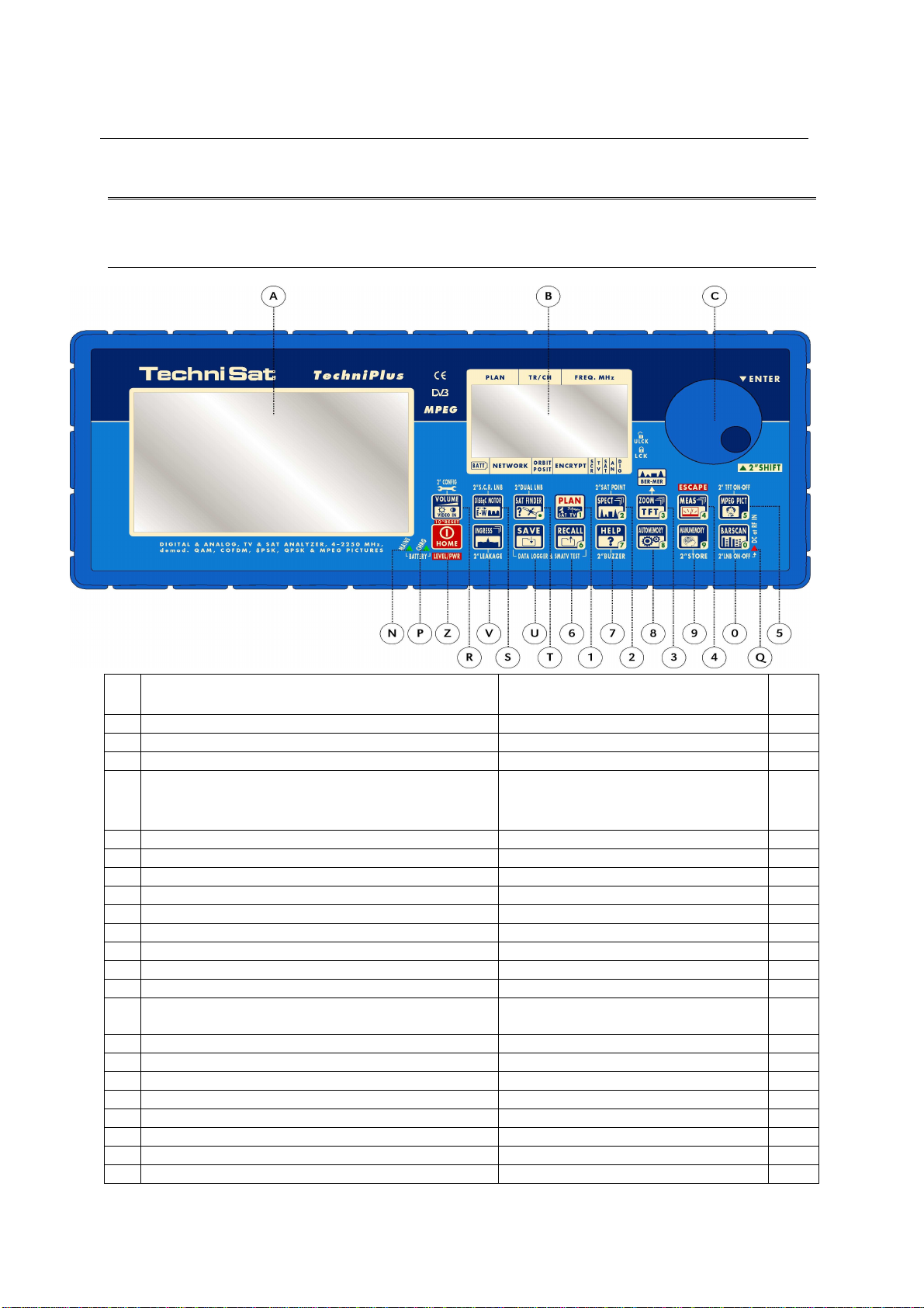
1 FRONT PANEL & KEYBOARD DESCRIPTION
A Graphic Display TFT
B Graphic Display LCD
C Select (rotate) and confirm (press) Direct Frequency Input
Z Main switch (ON/OFF)
MAIN FUNCTION
SECONDARY FUNCTION
(press and hold for 2”)
Level/Ch. Power meas. (press
Bloc
Num
once)
RESET (press and hold for 10”)
R VOLUME / VIDEO IN Setup menu configuration key
S S.C.R. LNB (single cable multi users installation) DUAL LNB (dual feed dish alignment)
T SAT FINDER
1 PLAN (channel plan, memory plan) 1
2 SPECT SAT POINT 2
3 ZOOM TFT (BER –MER) 3
4 MEAS (activates the measurements options) ESCAPE 4
5 MPEG PICT (shows the program list) Enable / Disable the TFT display 5
6 RECALL DATA LOGGER and SMATV TEST 6
7 HELP (authomatic identification of the
satellite/signal)
8 AUTOMEMORY (automatic search and storage) 8
9 MANUMEMORY (manual storage) STORE 9
0 BARSCAN Enable/Disable the RF feed 0
U SAVE DATA LOGGER and SMATV TEST
V DiSEqC MOTOR (motorized dishes managing)
N External Power supplier/adaptor LED indicator
P Battery charging LED indicator
Q RF feed LED indicator
BUZZER (antenna pointing aid) 7
,
The keys labeled through a number can also be used for direct frequency input.
8
Page 9
TECHNIPLUS / TECHNIPLUS HD
2 SIDE BODYPANELS
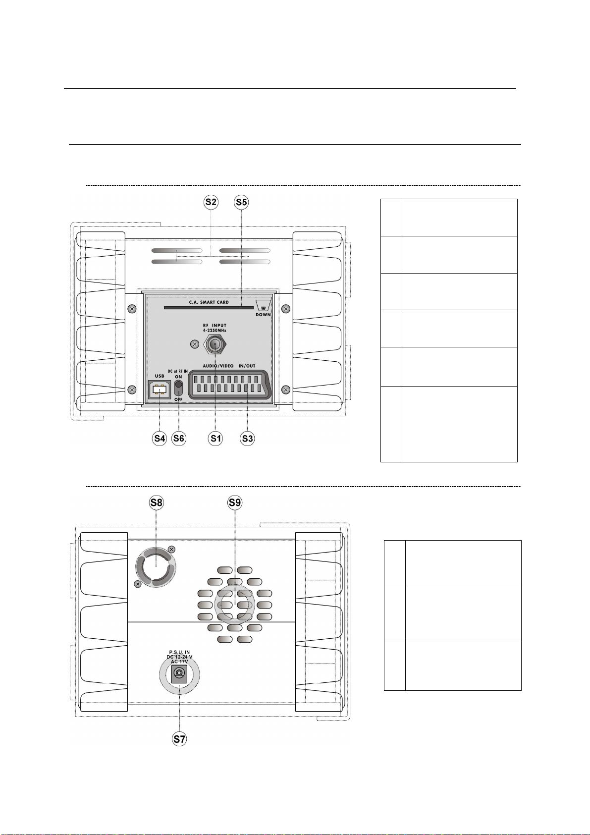
2.1 RIGHTSIDE BODYPANEL
USER MANUAL
S1
S2 Cooling grid (Air inlet)
S3
S4
S5
S6
RF input (“F” 75 Ohm
connector)
In - Out Audio/Video
SCART connection
USB connector for
Personal Computer
OPTIONAL
Conditional Access
Smart Card Reader
DC at RF IN bypass
switch (when in OFF
position no power
feed is provided
through the S1
connector)
2.2 LEFTSIDE BODYPANEL
External power input
S7
12 – 17 V AC
12 – 24 V DC
Ventilation fan (Air
S8
outlet)
S9 Built-in Loudspeaker
9
Page 10
TECHNIPLUS / TECHNIPLUS HD
USER MANUAL
SPEEDY MEASUREMENTS ?
The TECHNIPLUS is a really complete instrument: you will be able to perform a wide variety
of measurements on en extensive range of frequencies and of signal kinds.
This user manual will guide you throughout all the functionalities of your meter.
Should you need a brief shortcut to manage a specific kind of signal, please refer to the
content of this paragraph.
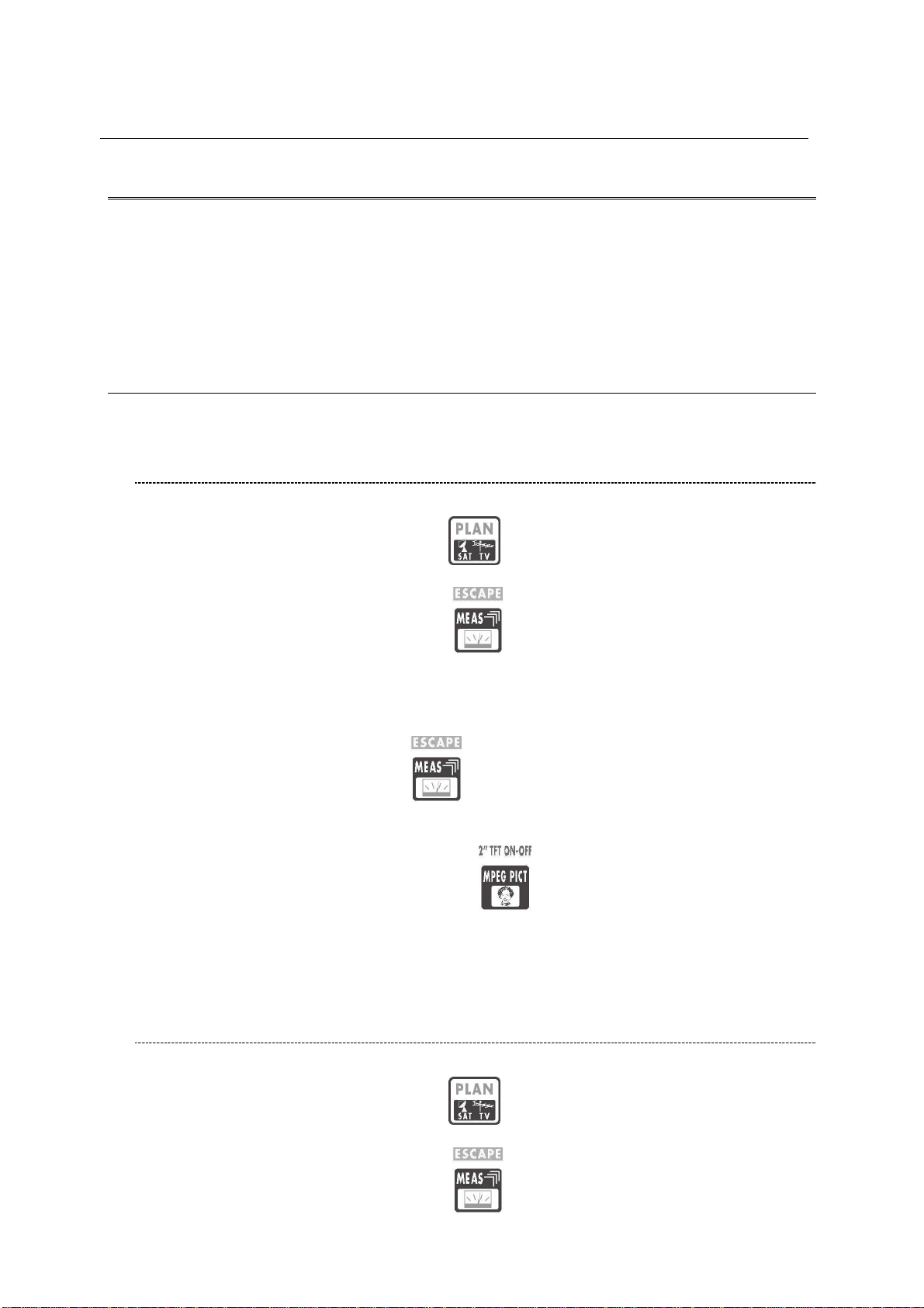
3 ONE TOUCH TO GO
3.1 ANALOGUE TV, DIGITAL (COFDM) TV AND QAM (CATV)
SIGNALS
1 Connect the signal cable to the F-type connector [S1] on the meter.
2 Press once and release the PLAN [1] key. Highlight the item TELEVISION
and select the proper Country Channel Plan.
3 Press once and release the MEAS [4] key.
4 Rotate the encoder [C] to navigate the selected Country Channel Plan. The
AUTODISCOVERY ® feature will automatically detect the signal type (analogue,
digital, QAM, …) as well as the related parameters (bandwidth, symbol rate, …)
and will properly tune it.
5 Press and release the MEAS [4] key to display the various measurements
screens. Each pulse on the MEAS [4] key will display a further measurement
screen, on a round-robin basis.
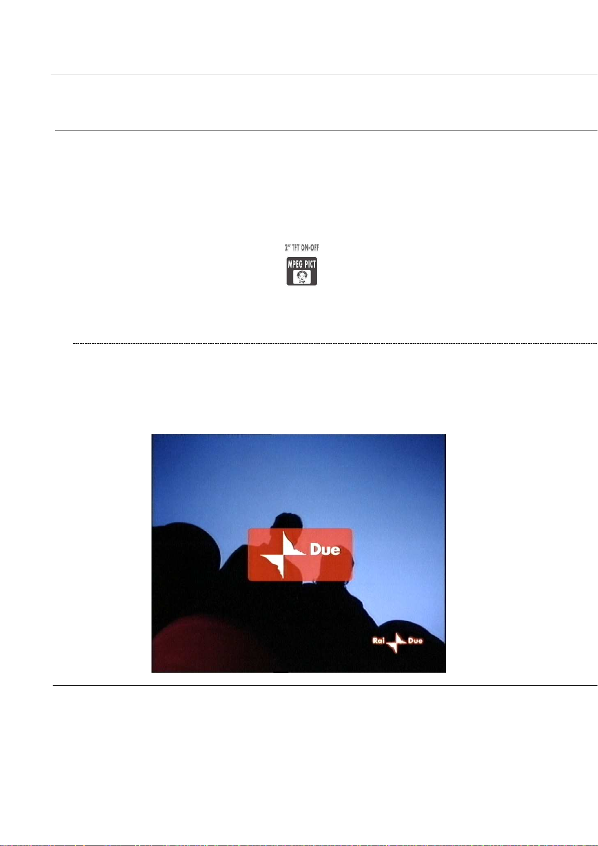
6 Press and hold for 2’’ the MPEG PICT [5] key to show the currently tuned
channel video signal (coming from the built-in demodulator) on the TFT display [A],
and to listen to the relevant audio through the meter built-in loud speaker.
3.2 ANALOGUE SATELLITE SIGNALS, DIGITAL QPSK
SATELLITE SIGNALS
1 Connect the signal cable to the F-type connector [S1] on the meter.
2 Press once and release the PLAN [1] key. Highlight the item SATELLITE
and select the required Satellite.
3 Press once and release the MEAS
10
[4] key.
Page 11
TECHNIPLUS / TECHNIPLUS HD
USER MANUAL
4 Rotate the encoder [C] to surf the various transponders of the selected satellite.
The AUTODISCOVERY ® feature will automatically detect the signal type
(analogue, digital, …) as well as the related parameters (bandwidth, symbol rate,
…) and will properly tune it.
5 Press and release the MEAS [4] key to display the various measurements
screens. Each pulse on the MEAS [4] key will display a further measurement
screen, on a round-robin basis.
6 Press and hold for 2’’ the MPEG PICT [5] key to show the currently tuned
transponder video signal (coming from the built-in demodulator, digital signals
only) on the TFT display [A], and to listen to the relevant audio through the meter
built-in loud speaker.
3.3 FM / FM RADIO SIGNALS [87,5 – 108 MHz]
1 Connect the signal cable to the F-type connector [S1] on the meter.
2 Press once and release the PLAN [1] key. Highlight the item MANUAL
MEMORY and select one of the MANU Memory Plans.
3 Press once and release the MEAS [4] key.
4 Rotate the encoder [C] and select a channel where no signal or an Analogue TV
signal is received.
5 Press and release repeatedly the MEAS [4] key up to display the main
Audio peak level measurement screen.
6 Using the Standard navigation Mode, highlight the tuned signal type (TV ANALOG
/ TV COFDM DVB-T/H) and select select the item FM RADIO.
7 Rotate the encoder [C] and select the desired frequency. The signal level is
displayed and the received audio signal can be listened through the meter built-in
loudspeaker
3.4 SPECTRUM ANALYZER FEATURE (ANY FREQUENCY)
1 Connect the signal cable to the F-type connector [S1] on the meter.
2 Tune the desired frequency (no matter if TV or Satellite).
3 Press once and release the SPECT [2] key to display the spectrum of the
current signal.
11
Page 12
TECHNIPLUS / TECHNIPLUS HD
USER MANUAL
USER MANUAL
4 TURN THE METER ON
Press and release the HOME [Z] key.
5 TURN THE METER OFF
Press and hold for 2’’ the HOME [Z] key.
6 CHECK THE BATTERY CHARGE STATUS
When the meter is on, at the bottom left corner of the LCD display [B] an icon will show
the current power source of the meter: built-in battery or mains external feed.
Build-in battery feed Mains external feed
Connect the supplied AC adaptor or the supplied cigarette lighter adaptor to the [S7]
inlet (located on the left side of the meter) to recharge the built-in battery. When the
meter is connected to an external power supply, the LED indicator [N] (located on the
meter front panel) turns on. When the external power connection is suitable to recharge the build-in battery, the LED indicator [P] ((located on the meter front panel)
also turns on.
When the meter is off, but it is still connected to an external power supply, the built-in
battery fast charge mode is activated, and the LED indicators [N] and [P] turn on
brighter.
Don’t leave the instrument in LOW BATTERY conditions (1/4 charge or less) for
more than 2 months to preserve the capabilities of the built-in battery. Should
the instruments be stored for longer periods, it is required to periodically charge
its battery.
12
Page 13
TECHNIPLUS / TECHNIPLUS HD
USER MANUAL
7 THE ENCODER – STANDARD NAVIGATION MODE
Navigate into the various functions and menus of the TECHNIPLUS is quick and easy.
A multi-function continuous encoder [C] allows the user to surf all the
meter functions, easily selecting the required function and quickly setting the desired
values, by simply rotating and pressing the encoder itself. Thanks to the ergonomic
design of the encoder knob just one hand is required.
When an item in the LCD [B] is black-highlighted, rotating the encoder [C] one step
clockwise will highlight the next item; rotating the encoder [C] one step counterclockwise will highlight the previous item.
Once black-highlighted the desired item, press and release the encoder knob, and the
black highlight will start blinking. When the black highlight is blinking, rotating the
encoder [C] one step clockwise will raise the value of the selected (highlighted) item;
rotating the encoder [C] one step counter-clockwise will decrease the value of the
selected (highlighted) item. Once set the appropriate value, just press and release the
encoder knob, and the black highlight will stop blinking, allowing you to move to a
different item by simply rotating the encoder knob.
These features will from now on be referred to as “Standard Navigation Mode”
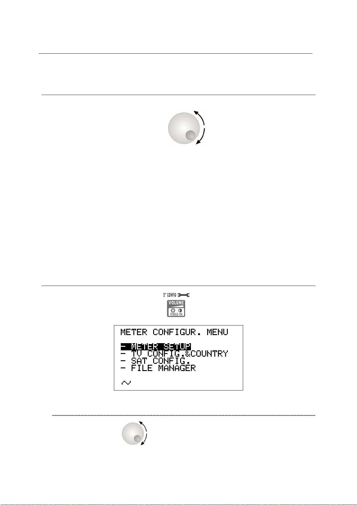
8 METER CONFIGURATION
Press and hold for 2” the VOLUME [R] key.
8.1 METER SETUP
Rotate the encoder [C] to highlight the item METER SETUP.
Press the encoder [C] to enter the meter setup menu.
13
Page 14

TECHNIPLUS / TECHNIPLUS HD
USER MANUAL
BATTERY SAVING – SELF POWER OFF (TIMER OFF)
If no key of the meter is pressed within the self power off time herein sat, the meter
automatically turns itself off in order to save battery life. To set up the auto power
off time, rotate the decoder [C] to highlight the item TIMER OFF, then press it. The
black icon which highlights the item POWER OFF starts blinking. Rotate the
encoder [C] and select: OFF (meter always on), 5 min (meter turns off in 5
minutes), 10 min (meter turns off in 10 minutes). OFF (meter always on). Press the
encoder [C] to enter your selection.
FIELD AND CHANNEL POWER MEASUREMENT UNIT
Using the Standard Navigation Mode, highlight the item UNIT and select the
requested measurement unit: dBm, dBmV (dBmillivolt) dBuV (dBmicrovolt)
LANGUAGE
Using the Standard Navigation Mode, highlight the item LANGUAGE and select
the required language. In some releases of the meter English language only might
be available.
KEYS BEEP
Using the Standard Navigation Mode, highlight the item KEYS BEEP and select
the desired keys beep volume: OFF, LOW, MEDIUM, HIGH (max.).
DISPLAY BACKLIGHT
If no key of the meter is pressed within the backlight power off time herein sat, the
display backlight automatically turns itself off in order to save battery life.
To set up the auto backlight power off time, highlight the item DISP.LIGHT using
the Standard Navigation Mode, then select FullON (backlight always on) or 30 sec
(backlight turns off within 30 sec).
14
Page 15
TECHNIPLUS / TECHNIPLUS HD
USER MANUAL
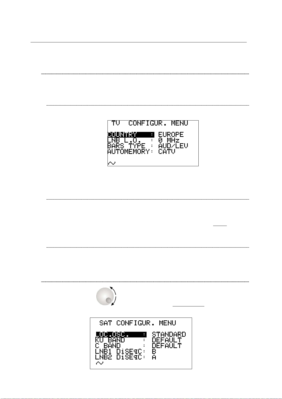
8.2 MAIN RECEPTION PARAMETER SETUP
Using the Standard Navigation Mode, highlight the item TV CONFIG.& COUNTRY.
Press the encoder [C] to enter the reception parameters setup menu.
COUNTRY CHANNEL PLAN
Rotate the encoder [C] to highlight the item COUNTRY.
Press the encoder [C] once. Then, using the Standard Navigation Mode, select the
relevant Country Channel Plan (for example: ITALY)
LOCAL OSCILLATOR (FREQUENCY)
Set up the appropriate local oscillator frequency value in case a frequency
conversion of the received signals is required, .
Highlight the item LNB L.O. using the Standard Navigation Mode, then set the
required frequency (rate) of the local oscillator. The default value is 0MHz (no
frequency conversion).
RF INPUT SIGNAL TYPE (CABLE OR OFF AIR)
Using the Standard Navigation Mode, highlight the AUTOMEMORY item select the
RF band, terrestrial analogue and digital, (TV ONLY) or cable (CATV).
8.3 SATELLITE RECEPTION SETUP
Rotate the encoder [C] to highlight the item SAT CONFIG, then press it to
enter the selection menu.
15
Page 16
TECHNIPLUS / TECHNIPLUS HD
USER MANUAL
LOCAL OSCILLATOR SETUP
Using the Standard Navigation Mode, highlight the item LOC.OSC. and select
STANDARD (signal coming directly from the antenna, down-conversion required)
or 0MHz(IF) (intermediate frequency signal, e.g. from a LNB).
LNB 1 ALLOWED POLARIZATION SETUP
Using the Standard Navigation Mode, highlight the item LNB1 DiSEqC and select
the required polarization for the LNB1 (A=4 polarizations, B=8 polarizations, C=12
polarizations, D=16 polarizations).
LNB 2 ALLOWED POLARIZATIONS SETUP
Using the Standard Navigation Mode, highlight the item LNB1 DiSEqC and select
the required polarization for the LNB2 (A=4 polarizations, B=8 polarizations, C=12
polarizations, D=16 polarizations).
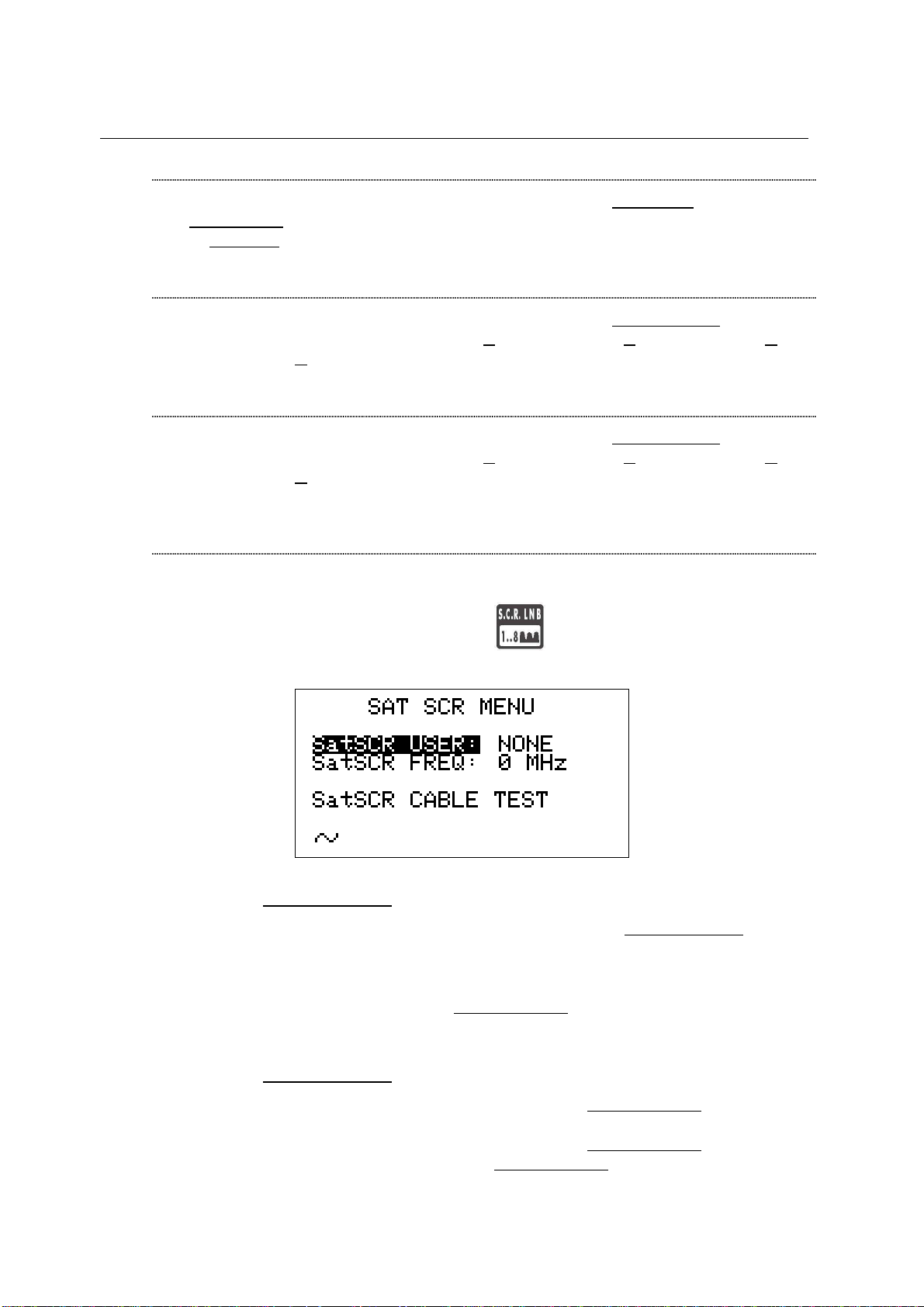
SINGLE-CABLE SCR COMPLIANT LNB OR MULTISWITCH SETUP : SAT
SCR MENU
This function allows the user to check and manage single cable multi-users
satellite installations.
Press once and release the S.C.R. LNB [S] key. The LCD [B] will display
the SAT SCR configuration menu:
SatSCR USER:
Using the Standard Navigation Mode, highlight the item SatSCR USER. and
select the appropriate user. Up to 8 different users can be set up together with
their relevant SCR frequency value.
To manually enter each frequency value, proceed as described at paragraph
SatSCR FREQ at page 16. If the SatSCR USER item is set to NONE, it won’t be
possible to set up any frequency value.
SatSCR FREQ:
Using the Standard Navigation Mode, highlight the SatSCR USER item and
select the User whose SCR frequency value has to be set up.
Using the Standard Navigation Mode, highlight the SatSCR FREQ item and set
up the required frequency value. If the SatSCR USER
won’t be possible to set any frequency value.
16
item is set to NONE, it
Page 17
TECHNIPLUS / TECHNIPLUS HD
USER MANUAL
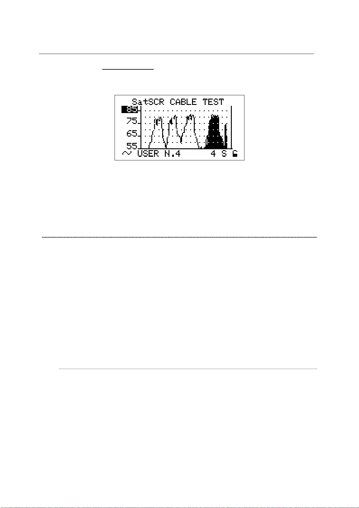
SatSCR CABLE
Using the Standard Navigation Mode, highlight the item SatSCR CABLE. Then
press the encoder [C] knob once and the LCD [B] will display:
The meter will perform the spectrum analysis for each user (from USER N.1 to
USER N.8).
The black-filled spectrum is referred to the currently selected user; the other
users’ signals appears as a shape.
Using the Standard Navigation Mode, you can set up the signal level end-ofscale.
8.4 ADVANCED SETTINGS
The patented Autodiscovery feature is capable to automatically detect the standard of
the tuned signal (analogue TV, DVB-T, DVB-S, QAM, …), the relevant bandwidth as
well as the appropriate Symbol Rate (where applicable). This feature allows the user to
navigate any frequency band by simply surfing the selected frequency band or by
simply adjusting the frequency value to be tuned; from time to time and with no action
by the user required the meter will detect the proper standard for the received signal,
and will set the meter accordingly to it, together with the appropriate measurements
set.
Under rare and very critical conditions (like a co-channel interference caused on a
DVB-T signal by an analogue TV signal receivable on the same channel and with a
comparable signal strength), the Autodiscovery system could set the meter to manage
the analogue signal (the interfering one) instead of the digital one.
In these conditions it is possibile to manually select the signal standard and the
relevant measurements set.
MANUAL SIGNAL STANDARD SELECTION
Select a User Defined (MANU) Memory Plan, as described at Chapter 10.2
“NAVIGATE INTO THE CHANNEL PLAN (USER DEFINED CHANNEL PLAN)” at
page 22. Using the Standard Navigation Mode tune the desired channel or the
desired frequency value.
From the channel power (or signal level) measurement screen, using the Standard
Navigation Mode, highlight the signal standard (TV ANALOG / TV COFDM DVBT/H / …) and select the requested one. Then press the encoder [C] knob to enter
your selection.
17
Page 18
TECHNIPLUS / TECHNIPLUS HD
USER MANUAL
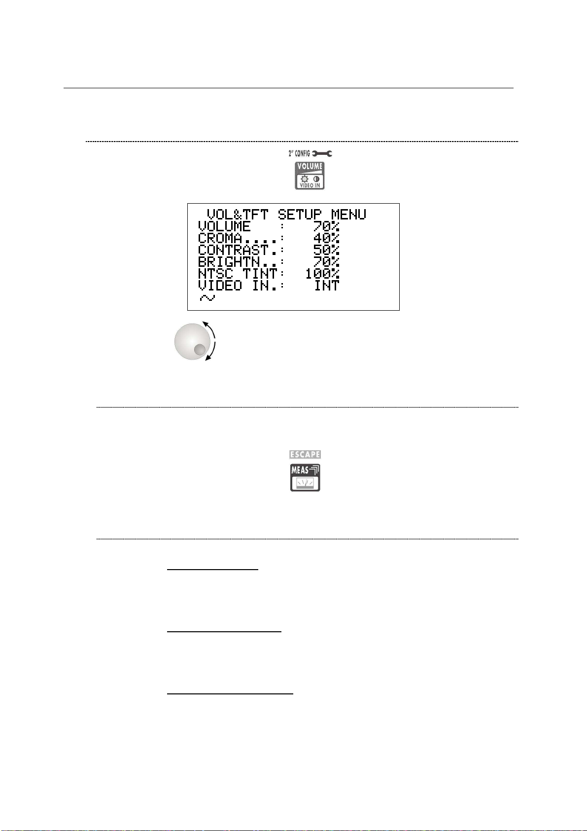
8.5 LOUDSPEAKER VOLUME AND TFT DISPLAY SETUP
Press once and release the VOLUME [R] key.
If the encoder [C] receives no input for 5”, the meter will quit to the last
performed function.
LOUDSPEAKER VOLUME SETUP
Using the Standard Navigation Mode, highlight the VOLUME item and set the
desired loudspeaker volume. Press once and release the encoder [C] knob to
enter your selection.
Press once and release the MEAS [4] key to quit the menu.
TFT DISPLAY SETUP
COLOR ADJUST
Using the Standard Navigation Mode, highlight the CROMA item and then set
the desired colour depth.
CONTRAST ADJUST
Using the Standard Navigation Mode, highlight the CONTRAST item and then
set the required contrast level.
BRIGHTNESS ADJUST
Using the Standard Navigation Mode, highlight the BRIGHTN. item and then set
the required brightness level.
18
Page 19

TECHNIPLUS / TECHNIPLUS HD
USER MANUAL
SCREEN ASPECT RATIO SELECTION (16:9 / 4:3)
Using the Standard Navigation Mode, highlight the VIDEO SIZE item and then
set the desired screen aspect ratio. An improper selection may result in image
distortion on the TFT [A] display, but won’t affect the measurement accuracy of
your meter.
VIDEO INPUT SELECTION
The TFT display [A] can be set to display the video signal from an external
source/device connected to the meter through the SCART connector [S3].
Using the Standard Navigation Mode, highlight the VIDEO IN item, and then
select INT (to display the signals coming from the meter built-in demodulator) or
EXT (to display the signals coming from an external device).
Press once and release the MEAS [4] key to quit this menu.
19
Page 20

TECHNIPLUS / TECHNIPLUS HD
USER MANUAL
9 DC AT RF IN
Press and hold for 2’’ the [0] key to activate the DC AT RF IN function
When the DC power at RF in is on, the yellow led DC at RF IN [Q] will be on.
WARNING: BEFORE ACTIVATING THE RF FEED, PLEASE CHECK WHETHER
THE RECEPTION SYSTEM (ANTENNA AND ACTIVE PARTS) CONNECTED TO
THE METER CAN BEAR AN RF POWER FEED.
Press and hold the BARSCAN [0] key for 2’’ to switch the DC at RF IN off. When the
RF feed is disabled, the yellow led DC at RF in [Q] will be off.
20
Page 21
TECHNIPLUS / TECHNIPLUS HD
USER MANUAL
TV SIGNALS – AUDIO FM – FM RADIO SIGNALS
ANALYZER
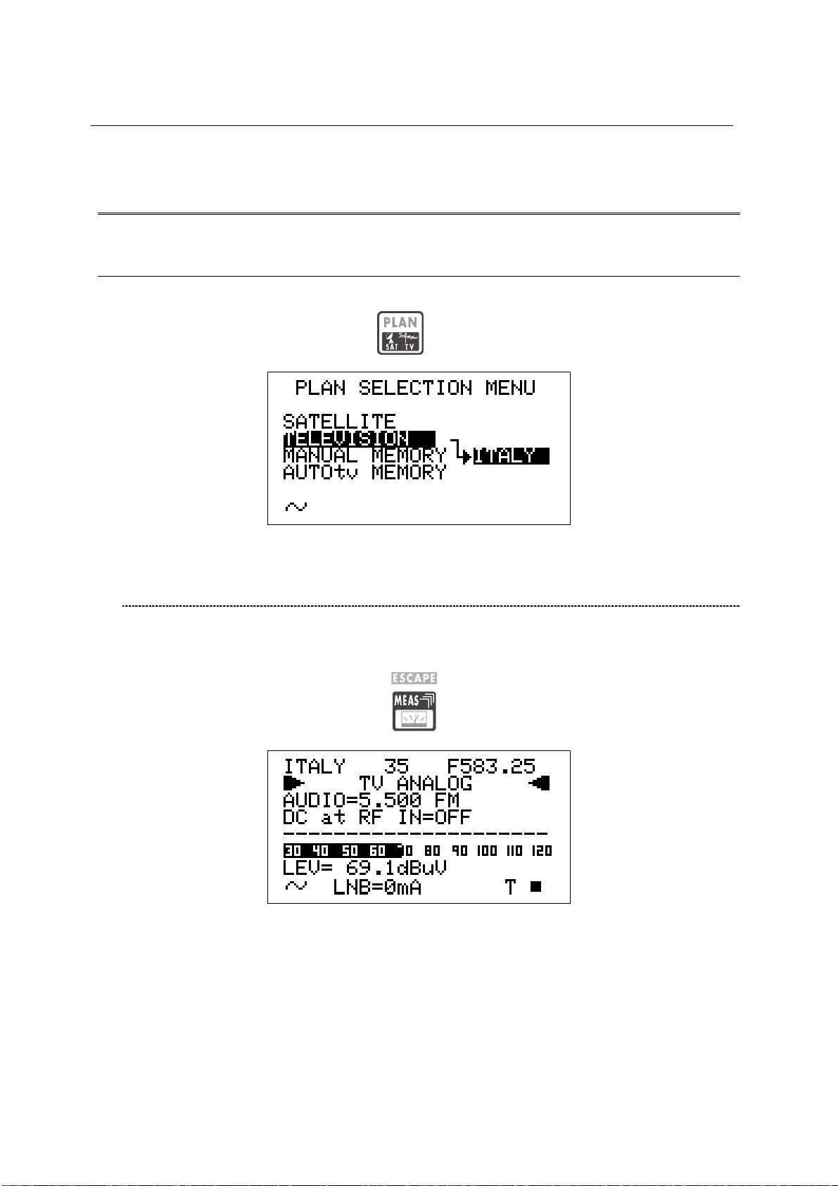
10 SIGNAL TUNING: PLAN
Connect the signal cable to the F-type connector [S1] on the meter.
Press once and release the PLAN [1] key.
10.1 NAVIGATE INTO THE SELECTED COUNTRY CHANNEL
PLAN
Using the Standard Navigation Mode, highlight the item TELEVISION.
Check the highlighted Country Channel Plan is the required one. If not, proceed as
described in Chapter 8.2 MAIN RECEPTION PARAMETER SETUP at page 15.
Press once and release the MEAS [4] key.
The LCD [C] top row will display (from left to right): the selected Country Channel
Plan, the channel currently tuned and the related frequency value.
Press the encoder [C] to highlight the current channel ID and rotate the encoder [C] to
surf the channels. Each step of the encoder moves the channel ID one step forward
or backward. To speed up the channel ID selection, rotate the encoder [C]
continuously.
21
Page 22
TECHNIPLUS / TECHNIPLUS HD
USER MANUAL
Press and hold for 2’’ the MPEG PICT [5] key to show the currently tuned
channel video signal (coming from the built-in demodulator) on the TFT display [A],
and to listen to the relevant audio through the meter built-in loud speaker.
10.2 NAVIGATE INTO THE CHANNEL PLAN (USER DEFINED
CHANNEL PLAN)
To create an User Defined Channel Plan, proceed as described at Chapter 15.2
“MANUALLY CREATING A MEMORY PLAN: MANUMEMORY” at page 50 .
Using the Standard Navigation Mode, highlight the item MANUAL MEMORY, then
select the required channels group (MANUxx plan).
Press once and release the MEAS [4] key.
The LCD [B] top row will display (from left to right): the selected channel plan, the
currently tuned channel and the corresponding frequency value.
Press the encoder [C] to highlight the current channel ID and rotate it to surf the
channels within the selected memory plan. Each step of the encoder moves the
channel ID one step forward or backward. To speed up the channel ID selection,
rotate the encoder [C] continuously.
Press and hold for 2’’ the MPEG PICT [5] key to show the currently tuned
channel video signal (croming from the built-in demodulator) on the TFT display [A],
and to listen to the relevant audio through the meter built-in loud speaker.
THE METER WILL TUNE ONLY THE CHANNELS INCLUDED IN THE SELECTED
CHANNEL PLAN. To explore/navigate into a new user defined channel plan,
press once and release the PLAN key and, using the Standard Navigation
Mode, highlight the MANUAL MEMORY item to select the required channel plan.
22
Page 23
TECHNIPLUS / TECHNIPLUS HD
USER MANUAL
FINE-TUNING THE FREQUENCY VALUE
Should you need to change the frequency value, using the Standard Navigation
Mode highlight the current frequency value and set the desired frequency value
(Frequency range: 45 – 878 MHz).
DIRECT FREQUENCY INPUT
Using the Standard Navigation Mode, highlight the current frequency value, and
then press and hold the encoder knob [C] for 3’’. The frequency value will be
reset and a black icon will appear to right of the “F” indicator.
This way, the BLOC NUM function is active. Enter the desired Frequency Value
(in MHz) using the numerical keys on the front panel (as described into the chart
FRONT PANEL AND KEYBOARD at page 8). To insert the comma (e.g.
frequency value: 839,25 MHz), press the SAT FINDER [T] key. Once entered the
desired frequency value, press the encoder knob[C] to confirm the selection.
in case the frequency value is not applicable or invalid in the TV service range
(e.g. 48354 MHz), the “OUT OF RANGE” warning will be displayed and the
entered value will be voided.
WHO IS THERE?AUTODISCOVERY ®
Once selected or fine-tuned the desired frequency value, the meter can provide
the user with the Autodiscovery ® function to self-detect and tune the received
signal, both analogue and digital, and to set the appropriate signal bandwidth.
Suppose you are starting from the frequency value 699,95 MHz, which has no
correspondence with any significant frequency value in any country channel
plan:
23
Page 24
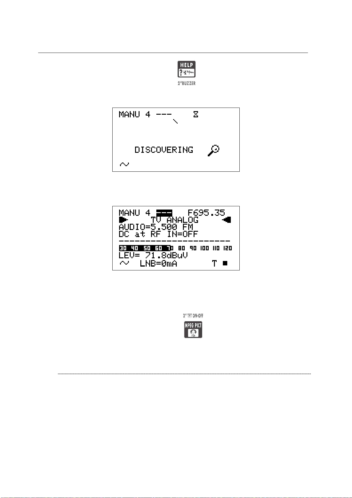
Press once and release the HELP [7] key. The meter will start the
Autodiscovery ® process and will display a rotating bar as an “in progress”
indicator.
When terminated, the meter displays the Autodiscovery ® results. In this case
the received signal was detected as analogue TV type at 695,35 MHz (as) video
carrier frequency.
TECHNIPLUS / TECHNIPLUS HD
USER MANUAL
In this case the meter was receiving an on-air analogue TV signal on EU channel
49, thus corresponding to a 695,25 video carrier frequency. From the practical
point of view, as well as from the end user one, the meter has correctly detected
the received signal even if the start frequency (699,95) was 4,6 MHz far from the
correct one.
Press and hold for 2’’ the MPEG PICT [5] key to display the demodulated
signal on the TFT [A] and to listen to the relevant audio through the meter built-in
loudspeaker.
FM /FM RADIO SIGNALS TUNING [87,5 – 108 MHz]
When in the main Audio peak level measurement screen, using the Standard
navigation Mode, highlight the tuned signal type (TV ANALOG / TV COFDM DVBT/H).
24
Page 25
TECHNIPLUS / TECHNIPLUS HD
USER MANUAL
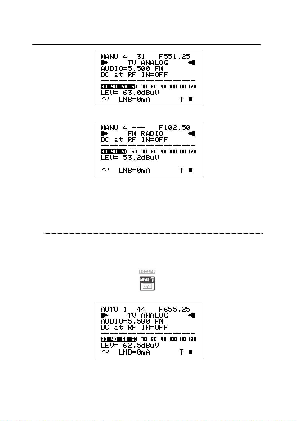
Using the encoder [C], select the item FM RADIO.
On the right handside of the F icon the tuned frequency is displayed, and the
received audio signal can be listened through the meter built-in loudspeaker.
Change the frequency value using the Standard Navigation Mode, or proceed as
described at page 23 DIRECT FREQUENCY INPUT
10.3 EXPLORE USER DEFINED CHANNEL
To create a channel plan (user defined list of channels), proceed as described in
Chapter 12 CREATE MEMORY PLANS at page 39.
Using the Standard navigation Mode, highlight the AUTOtv MEMORY item, and press
the encoder knob [C] once. The black icon of the AUTO memory plans will start
blinking. Rotate the encoder [C] to select the required channel groups.
Press once and release the MEAS [4] key.
Proceed as described in Chapter 10.2 NAVIGATE INTO THE CHANNEL PLAN
(USER DEFINED CHANNEL PLAN) at page 22.
25
Page 26
TECHNIPLUS / TECHNIPLUS HD
USER MANUAL
11 PERFORMING MEASURES: MEAS
The TECHNIPLUS is equipped with both one TFT [A] display and one LCD [B] display.
The use of the sole LCD [C] display extends the battery operating time.
On the other side, through the TFT [A] display the user can easily evaluate the tuned signal
and the relevant quality; at the same time, all the measurement values can be displayed on a
color TFT screen; their reading is immediate and intuitive, also under direct sunlight and in
any weather condition.
Press and hold for 2’’ the MPEG PICT [5] key to activate or switch off the TFT [A]
display
11.1 THE SELECTED CHANNEL CARRIERS ON AN ANALOGUE TV SIGNAL
VIDEO SIGNAL PEAK LEVEL MEASUREMENT
The demodulated video signal will be displayed on the TFT screen:
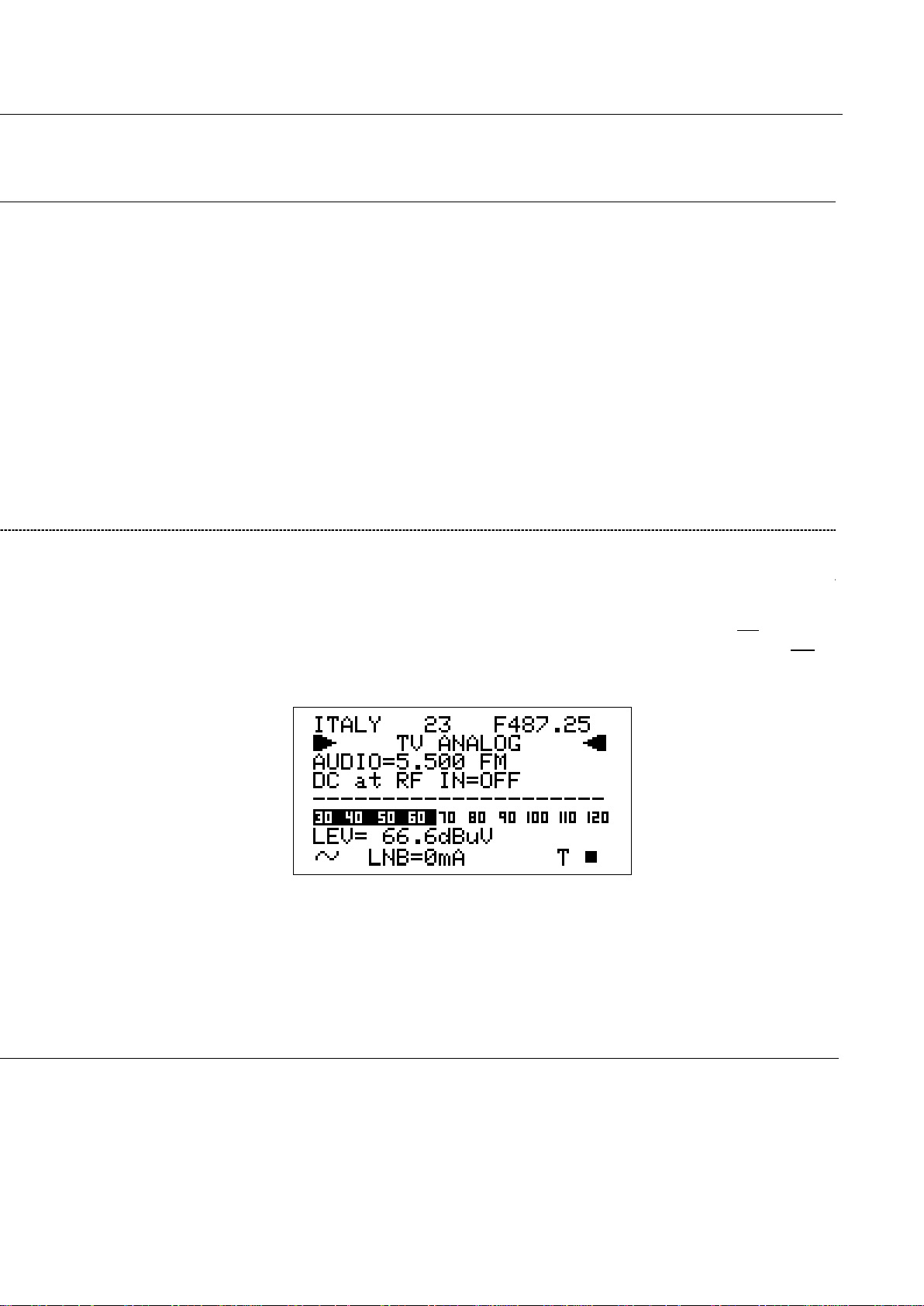
The LCD second row (from the top) displays “TV ANALOG”.
26 26 bis
Page 27
TECHNIPLUS / TECHNIPLUS HD
USER MANUAL
In the next pages each meter function, as well as any measurement feature, will be
described with a simultaneous reference to both the TFT display and the LDC one. The left
pages refer to the TFT [A] screen, the right ones refer to the LCD [B] screen.
Refer to the Chapter 10 SIGNAL TUNING: PLAN at page 21 to tune the desired channel.
On the bottom right side of the screen, the letter “T” will be displayed above the TV icon
marked on the display frame, and a black filled quadrangle will be displayed above the AN
icon marked on the display frame.
The current video signal peak level will be displayed on the bottom of the screen, together
with the relevant measurement unit. The video signal peak level real time value is also
displayed on a level bar with peak level memory.
Page 28
TECHNIPLUS / TECHNIPLUS HD
USER MANUAL
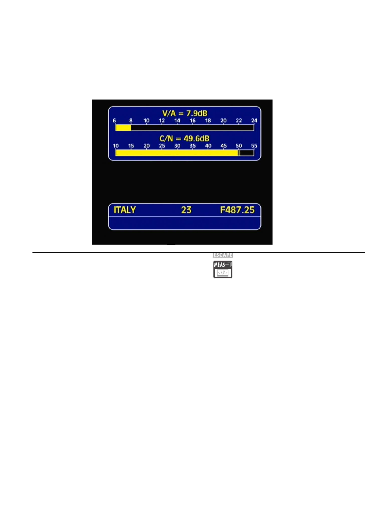
VIDEO Vs. AUDIO PEAK LEVEL RATIO AND SIGNAL TO NOISE RATIO
From the previous measurement screen, press once and release the MEAS [4] key.
The Video Vs. Audio peak level ratio and the signal to noise ratio will be displayed.
By repeatedly pressing and releasing the MEAS [4] key the above mentioned
screens will appear in sequence.
SPECTRUM ANALYSIS OF THE TUNED CHANNEL
Proceed as described in Chapter 12 SPECTRUM ANALYZER MODEat page 40.
27 27 bis
Page 29
TECHNIPLUS / TECHNIPLUS HD
USER MANUAL
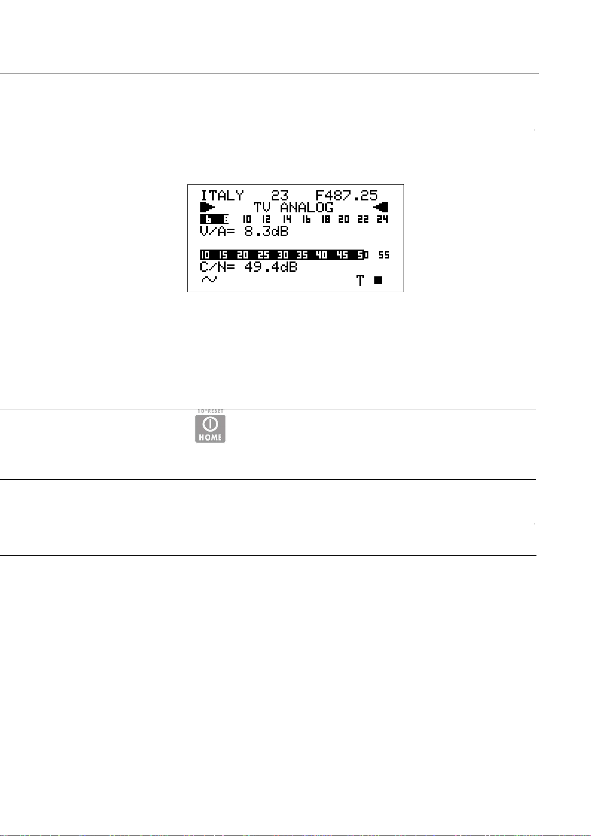
The meter will display the Video peak level Vs. Audio peak level Ratio (V/A, in dB) and the
Signal to Noise Ratio (C/N, in dB). Both the real time Ratios are also displayed on level bars
with peak level memory.
Press once and release the [Z] key once to directly enter the Video signal peak level
measurement.
Page 30

TECHNIPLUS / TECHNIPLUS HD
USER MANUAL
11.2 THE SELECTED CHANNEL CARRIERS ON A DTT (COFDM) SIGNAL
THE CHANNEL IS SUCCESSFULLY LOCKED (THE LOCK ON THE LCD BOTTOM-RIGHT CORNER IS CLOSED)
NOISE MARGIN, QUALITY TEST, MER AND SNR MEASUREMENTS
On the TFT screen the decoded video signal of the first program in the DVB-T bouquet
(detected by the meter according to the MPEG2 tables of the same bouquet) will be
displayed as a backgroung, and the main data of the tuned signal will be displayed.
The second row of the LCD [B] displays TV COFDM DVB-T&H.
BER MEASUREMENTS BEFORE AND AFTER ERROR CORRECTION VITERBI
From the previous measurement screen (TFT), press once and release the MEAS [4] key
once. The BER before Viterbi error correction (in this meter labeled as bBER or preBER)
and the BER after Viterbi error correction (in this meter labeled as aBER or posBER)
28 28 bis
Page 31

TECHNIPLUS / TECHNIPLUS HD
USER MANUAL
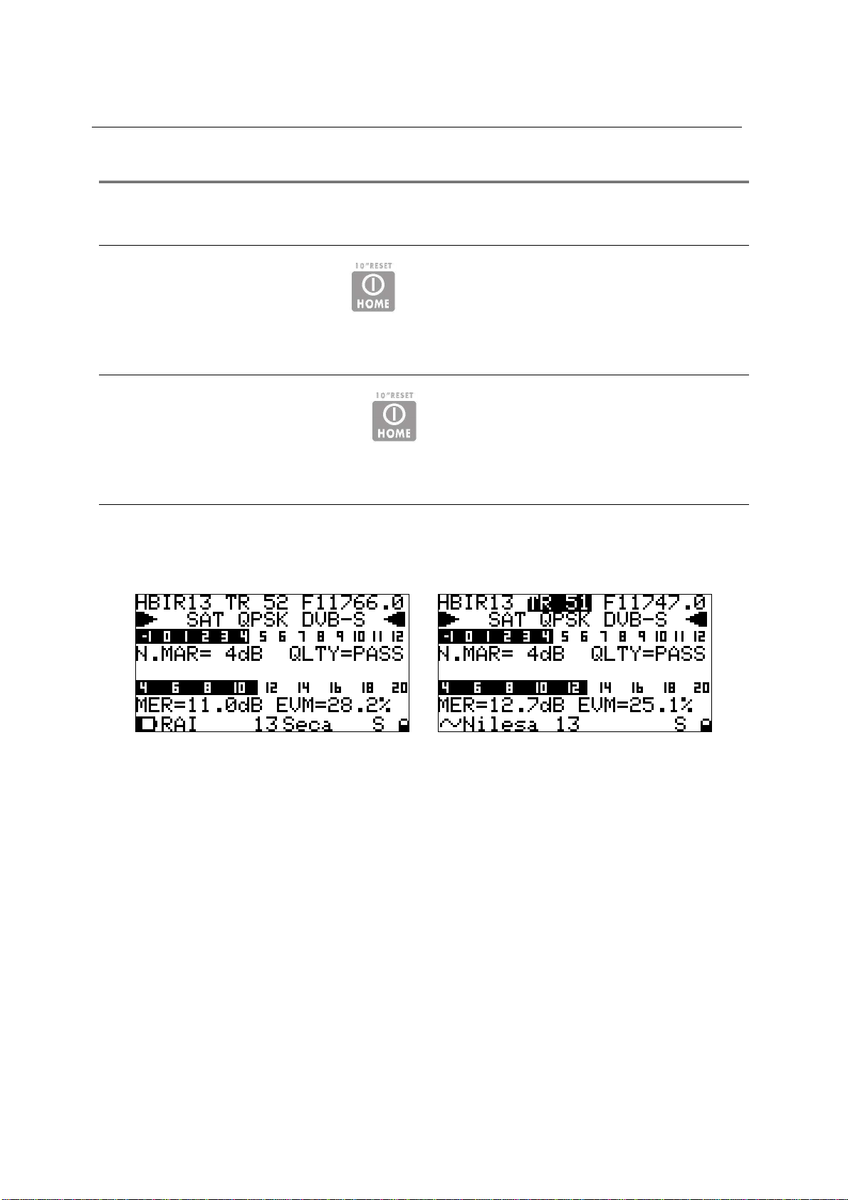
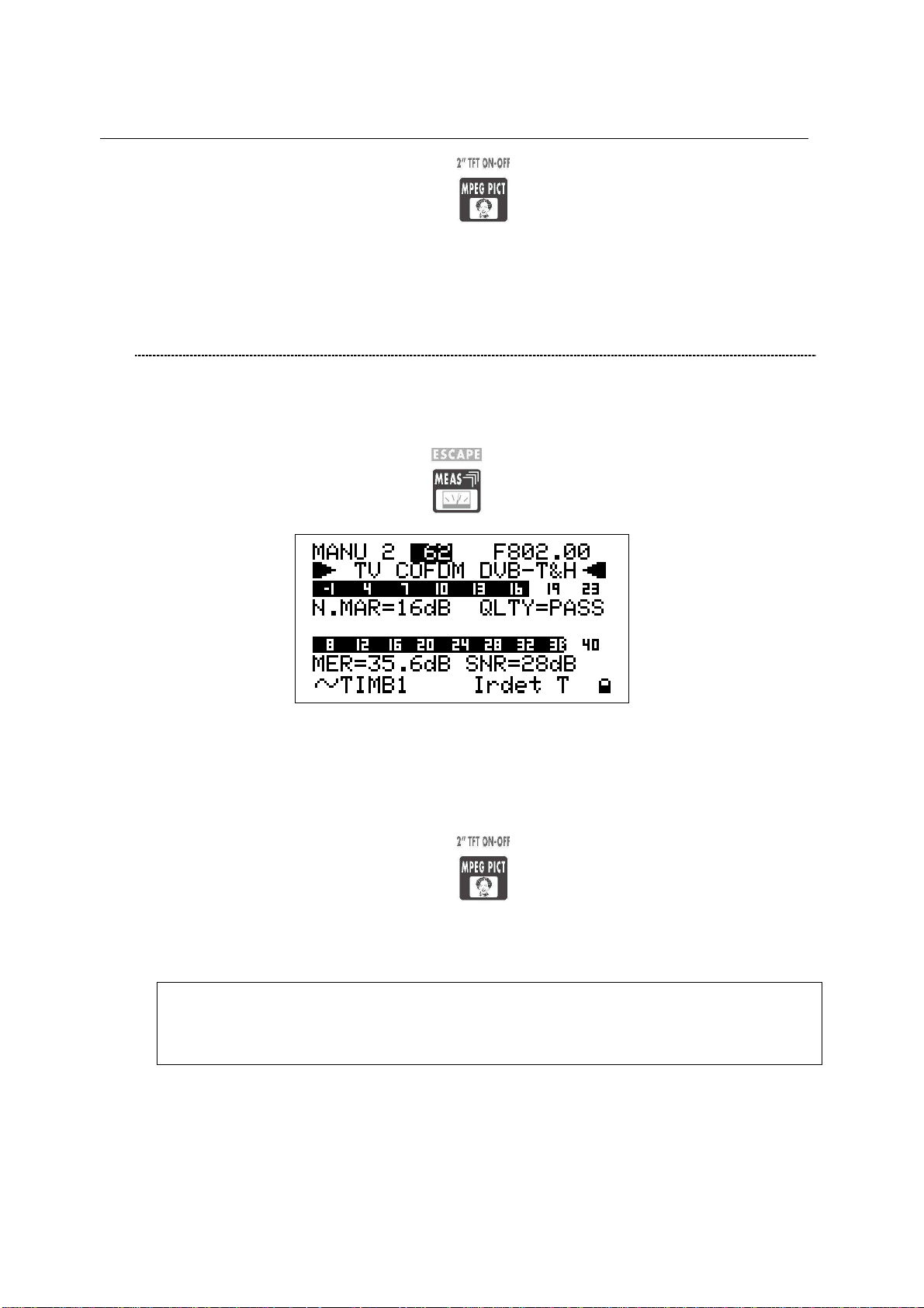
When the channel is properly locked, the first screen of the meter shows the Noise Margin
value (N.MARG), the result of the real time quality test (QLTY, FAIL, MARG. and PASS),
and the MER and SRN measurements. The Noise Margin and the MER measurements are
also displayed on level bars with peak level memory.
Furthermore, the bottom row of the LCD will display the main information of the tuned
bouquet:
• Bouquet name (network name), after some seconds and under acceptable
receiving conditions.
• Encryption system (encrypt), if there is at least one encrypted program in the
bouquet, after some seconds and in acceptable receiving conditions.
• T, above the TV icon on the LCD [B] frame
• A closed lock in the bottom right corner of the LCD [B]
parameters will be displayed.
Page 32

TECHNIPLUS / TECHNIPLUS HD
USER MANUAL
Press once and release the ZOOM TFT [3] key.
On the background of the decoded video signal, a close-up table of the main reception
parameters will be displayed. This table resumes all the signal parameters required to
successfully align the antenna and to define the quality of the detected signal (Noise Margin,
MER, bBER, aBER, C/N, channel power), as well as to detect the main features of the signal
(DVB-T or DVB-H, QAM order, number of carriers, Guard Interval, High and Low Priority
FEC, hierarchic modulation).
29 29 bis
Page 33

TECHNIPLUS / TECHNIPLUS HD
USER MANUAL
These measurements are also displayed on a level bar with peak level memory.
Page 34

CONSTELLATION CHART AND OFDM PARAMETER
From the previous measurement screen, press once and release the MEAS [4] key.
TECHNIPLUS / TECHNIPLUS HD
USER MANUAL
The constellation will be displayed together with the following parameters:
This meter allows to zoom-in the upper-right quadrant of the constellation chart.
Using the Standard Navigation Mode, highlight the ZOOM item
30 30 bis
Page 35

TECHNIPLUS / TECHNIPLUS HD
USER MANUAL
• Bandwidth of the tuned signal (COFDM)
• Modulation / Order of QAM (MODE)
• Number of Carries and modulation system (CARR)
• Guard Interval (G.INT)
• High and Low Priority stream code rate (HP / LP)
• Hierarchic modulation mode active (HIER)
and select the zoom level: just the upper-right quadrant of the complete constellation
(both I and Q positive), the top right section of the first quadrant, or the whole
constellation chart.
Page 36

IMPULSE RESPONSE OF THE SELECTED CHANNEL
From the previous measurement screen (TFT), press once and release the MEAS [4] key.
The impulse response of the tuned channel will be displayed.
TECHNIPLUS / TECHNIPLUS HD
USER MANUAL
To tune a different channel, using the Standard Navigation Mode, highlight the channel
ID item and select the required channel.
WARNING: only the channels included into the Channels Plan (PLAN) in use will be
displayed.
Refer to Chapter 10 SIGNAL TUNING: PLAN at page 21
To switch from the time to space domain for the echoes measurement, using the
Standard Navigation Mode highlight the (DIST or TIME) item at the top of the vertical
axis and select the required domain.
31 31 bis
Page 37

TECHNIPLUS / TECHNIPLUS HD
USER MANUAL
The meter assumes as main signal (i.e. the signal with zero delay) the “echo” with the
highest level among all the detected signals.
To change the marker position, using the Standard Navigation Mode highlight the
echoes position item located at the top right side of the display and sweep the marker
position. The current marker position is shown on the display through a vertical dotted
row.
The marker can also be moved in the negative portion of the selected domain (both
time and space). Into the negative portion the echoes:
• occurring before the main signal (PRE ECHOES) and
• whose level is below the main signal level
can be found.
Page 38

TECHNIPLUS / TECHNIPLUS HD
USER MANUAL
BOUQUET DATA ID
From the previous measurement screen, press once and release the MEAS [4] key.
CHANNEL POWER MEASUREMENT
From the previous measurement screen, either Press once and release the MEAS [4] key once or
under any circumstance press the HOME [Z] key once to enter the channel power measurement.
32 32 bis
Page 39

TECHNIPLUS / TECHNIPLUS HD
USER MANUAL
In case the tuned bouquet contains the relevant information, the LCD will display:
• the network name (NETW. NAME)
• the bouquet name (BOUQ. NAME)
• the current date (DATE), as stated in the bouquet itself
Any information missing not included in the bouquet will result in a blank field. Anyway, the
signal is properly locked even when one or all of said information is missing provided that
the lock at the LCD bottom right corner is closed.
On the LCD bottom row, the channel power measurement, together with the relevant
measurement unit will be displayed. This real time value is also displayed on a level bar with
peak level memory.
WHILE PERFORMING SUCH MEASUREMENTS, THE LOCK DISPLAYED AT BOTTOM
RIGHT SIDE OF THE SCREEN WILL BE OPEN. THIS IS BECAUSE THE METER
EXPLORES THE WHOLE CHANNEL BAND IN ORDER TO DETECT THE TRUE
CHANNELPOWER.
However in the following measurement screens, the signal will be displayed as correctly locked.
Page 40

All the six measurements screens above described, and related to DTT (COFDM)
signals will be cyclically displayed by repeatedly pressing the MEAS [4] key.
DISPLAYING THE SERVICE LIST OF THE CURRENT BOUQUET
Press once and release the MPEG PICT [5] key once.
TECHNIPLUS / TECHNIPLUS HD
USER MANUAL
33 33 bis
Page 41

TECHNIPLUS / TECHNIPLUS HD
USER MANUAL
Press once and release the HOME [Z] key to directly switch to the channel power
measurement.
The LCD [B] will display:
• the full program list of the currently tuned bouquet;
• the relevant video (Vpid) and audio (Apid) PIDs, and
• the encryption status key (Y= encrypted, N= not encrypted/free to air).
It might take few second to get the full information displayed.
Rotate the encoder [C] to scroll down the program list (up to 64). The highlighted program
will be displayed on the TFT screen and the relevant audio will be played through the
meter built-in loudspeaker.
Press once and release the MEAS [4] key to quit to the previous measurement screen.
Page 42

BUZZER FUNCTION (ASSISTED ANTENNA ALIGNMENT)
Press and hold for 2’’ the HELP [7] key. You can hear a beep whose duty cycle
is proportionally to the signal Noise Margin.
TECHNIPLUS / TECHNIPLUS HD
USER MANUAL
This is an antenna alignment aid feature. The buzzer tone can be activated only when the
SPECTRUM ANALYZER MODE
Proceed as described in Chapter 12 SPECTRUM ANALYZER MODEat page 40.
THE CHANNEL IS NOT SUCCESSFULLY LOCKED (THE LOCK ON THE LCD
BOTTOM-RIGHT CORNER IS OPEN)
The meter will display as first measurement screen the channel power measurement (see
the Chapter CHANNEL POWER MEASUREMENT at page 32).
The further measurement screens, related to DTT (COFDM) signals will be cyclically
displayed by repeatedly pressing the MEAS [4] key.
34 34 bis
Page 43

TECHNIPLUS / TECHNIPLUS HD
USER MANUAL
received digital signal is correctly locked. The LCD [B] will display:
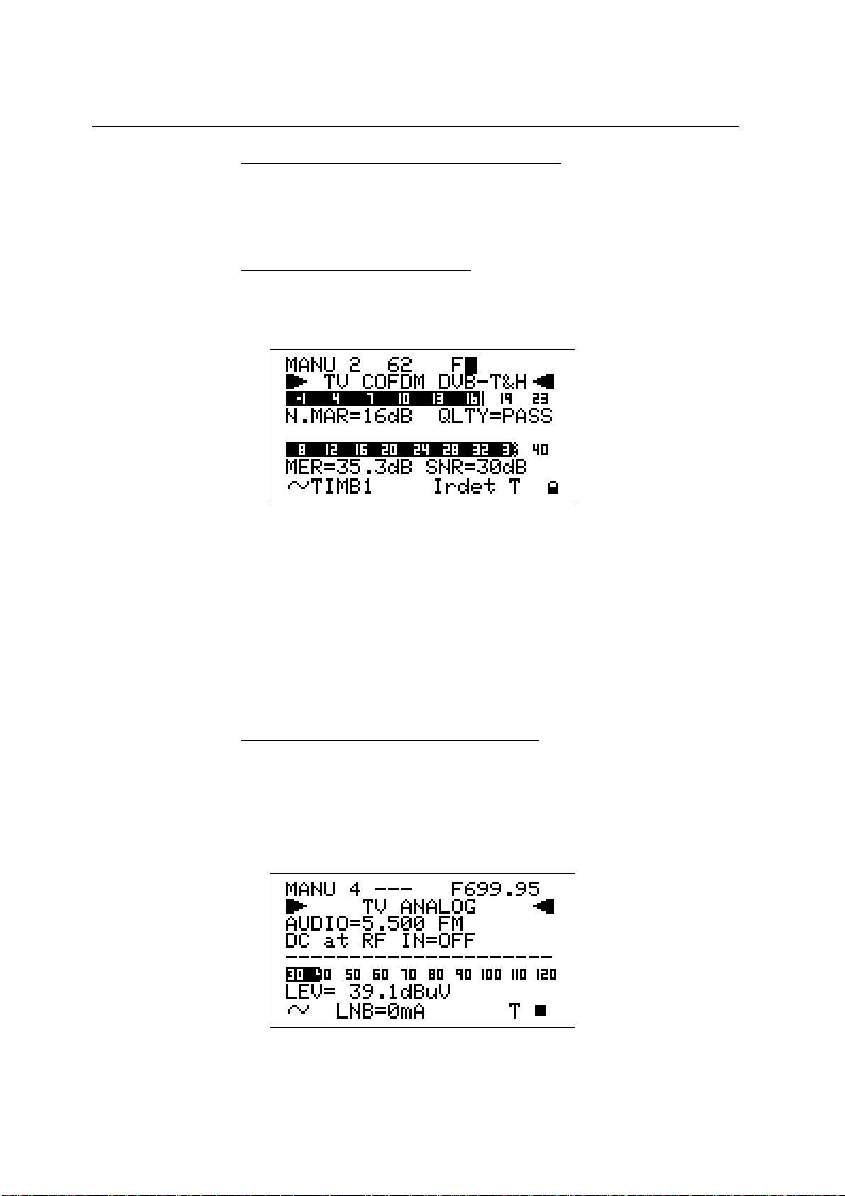
The LCD [B] second row shows (from the left): the memory plan in use, the currently tuned
channel ID and the relevant frequency value. The frequency value can be changed using
the Standard Navigation Mode.
The bottom section of the display shows the Noise Margin measurement (also on a level bar
with peak memory display) and the result of the signal quality test (PASS, MARGINAL,
FAIL).
Press any key to deactivate the buzzer tone and to quit this function.
From any measurement screen press once and release the HOME [Z] key to
directly perform the channel power measurement.
WARNING: the buzzer function is active only with digital signals.
It cannot be activated for analogue signals
Page 44

TECHNIPLUS / TECHNIPLUS HD
USER MANUAL
11.3 THE SELECTED CHANNEL CARRIES ON A QAM (CATV) SIGNAL
THE CHANNEL IS SUCCESSFULLY LOCKED (THE LOCK ON THE LCD
BOTTOM-RIGHT CORNER IS CLOSED)
The Autodiscovery will automatically detect the QAM signal type, The second row of the LCD [B] displays TV QAM, together with the relevant standard
NOISE MARGIN, QUALITY TEST, MER AND BLOCK ERROR MEASUREMENTS
The TFT screen [A] will display the main data of the tuned signal.
The second row from the top will display the Network Name and the relevant
broadcasting standard (e.g.: DVB-C).
The second row of the LCD [B] displays TV QAM and the relevant standard.
In the left handside column the measurements related to the signal quality are real
time displayed: NOISE MARGIN, N.MARG, MER, BER before (bBER) and after
(aBER) Viterbi convolutionary decoding. In the right handside column one can find the
MPEG Block Error Count (ErCnt, starting when the signal is locked), the modulation
type (in this case 64 QAM) and the signal Symbol Rate.
In the bottom section of the screen the real time Channel Power measurement and the
Quality Test results are displayed. Both measurements are also displayed on level
bars whose color varies according to the measurement result: red=critical, yellow=fair,
green=excellent.
35 35 bis
Page 45

TECHNIPLUS / TECHNIPLUS HD
(e.g.: DVB-C).
USER MANUAL
When the channel is properly locked, the first screen of the meter shows the Noise Margin
value (N.MARG), the result of the real time quality test (QLTY, FAIL, MARG. and PASS),
and the MER and MPEG Block Error (BlkEr) measurements. The Noise Margin and the
MER measurements are also displayed on level bars with peak level memory.
Furthermore, the bottom row of the LCD will display the main information of the tuned
bouquet:
• Bouquet name (network name), after some seconds and under acceptable
receiving conditions.
• Encryption system (encrypt), if there is at least one encrypted program in the
bouquet, after some seconds and in acceptable receiving conditions.
• C, above the TV icon on the LCD [B] frame
• A closed lock in the bottom right corner of the LCD [B]
Page 46

BER MEASUREMENTS BEFORE AND AFTER VITERBI ERROR CORRECTION
TECHNIPLUS / TECHNIPLUS HD
USER MANUAL
CONSTELLATION CHART AND QAM PARAMETER
From the previous measurement screen, press once and release the MEAS [4] key.
From the previous measurement screen (TFT), press once and release the MEAS [4] key
The constellation will be displayed together with the following parameters:
36 36 bis
Page 47

TECHNIPLUS / TECHNIPLUS HD
USER MANUAL
once. The BER before Viterbi error correction (in this meter labeled as bBER or preBER)
and the BER after Viterbi error correction (in this meter labeled as aBER or posBER)
parameters will be displayed.
These measurements are also displayed on a level bar with peak level memory.
• The broadcasting standard of the tuned signal (Annex)
• The QAM modulation mode (MODE)
• The signal Symbol Rate (SR)
Page 48

This meter allows to zoom-in the upper-right quadrant of the constellation chart.
Using the Standard Navigation Mode, highlight the ZOOM item
TECHNIPLUS / TECHNIPLUS HD
USER MANUAL
and select the zoom level: just the upper-right quadrant of the complete constellation
BOUQUET DATA ID
From the previous measurement screen, press once and release the MEAS [4] key.
In case the tuned bouquet contains the relevant information, the LCD will display:
• the network name (NETW. NAME)
• the bouquet name (BOUQ. NAME)
• the Transport Stream identificator (TSID)
• the Network identity (NID)
• the encryption system of the tuned signal, if any
• the current date (DATE), as stated in the bouquet itself
Any information missing not included in the bouquet will result in a blank field.
37 37 bis
Page 49

TECHNIPLUS / TECHNIPLUS HD
USER MANUAL
(both I and Q positive), the top right section of the first quadrant, or the whole
constellation chart.
In case the tuned bouquet contains the relevant information, the LCD will display:
• the network name (NETW. NAME)
• the bouquet name (BOUQ. NAME)
• the current date (DATE), as stated in the bouquet itself
Any information missing not included in the bouquet will result in a blank field. Anyway, the
signal is properly locked even when one or all of said information is missing provided that
the lock at the LCD bottom right corner is closed.
Page 50

CHANNEL POWER MEASUREMENT
TECHNIPLUS / TECHNIPLUS HD
USER MANUAL
From the previous measurement screen, either Press once and release the MEAS [4] key once or
under any circumstance press the HOME [Z] key once to enter the channel power measurement.
All the various measurements screens above described, and related to QAM (CATV) signals will be
cyclically displayed by repeatedly pressing the MEAS [4] key.
38 38 bis
Page 51

TECHNIPLUS / TECHNIPLUS HD
USER MANUAL
On the LCD bottom row, the channel power measurement, together with the relevant
measurement unit will be displayed. This real time value is also displayed on a level bar with
peak level memory.
WHILE PERFORMING SUCH MEASUREMENTS, THE LOCK DISPLAYED AT BOTTOM
RIGHT SIDE OF THE SCREEN WILL BE OPEN. THIS IS BECAUSE THE METER
EXPLORES THE WHOLE CHANNEL BAND IN ORDER TO DETECT THE TRUE
CHANNELPOWER.
However in the next measurement screens, the signal will be displayed as correctly locked.
Press once and release the HOME [Z] key to directly switch to the channel power
measurement.
Page 52

DISPLAYING THE SERVICE LIST OF THE CURRENT BOUQUET
Press once and release the MPEG PICT [5] key once.
TECHNIPLUS / TECHNIPLUS HD
USER MANUAL
SPECTRUM ANALYZER MODE
Proceed as described in Chapter 12 SPECTRUM ANALYZER MODE at page 40.
THE CHANNEL IS NOT SUCCESSFULLY LOCKED (THE LOCK ON THE LCD
BOTTOM-RIGHT CORNER IS OPEN)
The meter will display as first measurement screen the channel power measurement (see
the Chapter CHANNEL POWER MEASUREMENT at page 32).
The further measurement screens, related to DTT (COFDM) signals will be cyclically
displayed by repeatedly pressing the MEAS [4] key.
39 39 bis
Page 53

TECHNIPLUS / TECHNIPLUS HD
USER MANUAL
The LCD [B] will display:
• the full program list of the currently tuned bouquet;
• the relevant video (Vpid) and audio (Apid) PIDs, and
• the encryption status key (Y= encrypted, N= not encrypted/free to air).
It might take few second to get the full information displayed.
Rotate the encoder [C] to scroll down the program list (up to 64). The highlighted program
will be displayed on the TFT screen and the relevant audio will be played through the
meter built-in loudspeaker.
Press once and release the MEAS [4] key to quit to the previous measurement screen.
From any measurement screen press once and release the HOME [Z] key to
directly perform the channel power measurement
Page 54

TECHNIPLUS / TECHNIPLUS HD
USER MANUAL
12 SPECTRUM ANALYZER MODE
Press once and release the SPECT [2] key to display the spectrum of the current
signal.
In case the tuned signal is digital, the marker will be positioned by default on the centre-band
frequency of the tuned signal. The relevant level is displayed in the LCD bottom row (MKR),
together with the relevant measurement unit.
40 40 bis
Page 55

TECHNIPLUS / TECHNIPLUS HD
USER MANUAL
In case the tuned signal is analogue, the marker will be positioned by default on the
frequency value corresponding to the analogue Video signal peak level. The relevant level is
displayed in the LCD bottom row (MRK), together with the relevant measurement unit.
Page 56

TECHNIPLUS / TECHNIPLUS HD
USER MANUAL
12.1 SURFING THE CHANNELS
Using the Standard Navigation Mode, highlight the currently tuned channel ID, then select
the desired channel ID.
12.2 MOVING THE MARKER (FREQUENCY VALUE)
Using the Standard Navigation Mode, highlight the frequency item, then move the marker
position (current frequency value).
The meter LCD will at any time display the current frequency value (first row, top right) and
12.3 EDITING THE SIGNAL LEVEL END OF SCALE
Using the Standard Navigation Mode, highlight the top level (end of scale) value on the yaxis, then select the desired end of scale value.
.
12.4 EDITING THE SPAN VALUE
Using the Standard Navigation Mode, highlight the span (SP) value.. Then select the desired span value. Only pre-defined span values (from 2 MHz to FULL)
12.5 ACTIVATE THE MAX HOLD FUNCTION
Press once and release the SPECT [2] key. The MaxH icon will be displayed on the bottom
row in correspondence with the “ENCRYPT” item on the right edge of the display.
12.6 FULL BAND MAPPING
The meter can display a bar diagram in which each bar displays the signal level detected
on a specific channel into the whole selected frequency band. The bar diagram, the marker,
and the display bottom row can display several parameters, depending on the meter
configuration.
FULL BAND MAPPING DISPLAY CONFIGURATION
Press and hold for 2’’ the VOLUME [R] key. Using the Standard Navigation Mode,
highlight the TV CONFIG.& COUNTRY item, then press the encoder knob to enter the
configuration menu.
SIGNAL LEVEL / CHANNEL POWER DETECTED INTO EACH
CHANNEL (BARSCAN)
Press once and release the SPECT [2] key again to quit the MaxHold function.
Using the Standard Navigation Mode, highlight the BARS TYPE item and select the
Using the Standard Navigation Mode, select the LEVEL item. Each bar will display the
real time video signal peak level (analogue signals) or the real time channel power
(digital signals) detected in the corresponding frequency channel.
41 41 bis
Page 57

TECHNIPLUS / TECHNIPLUS HD
USER MANUAL
WARNING: only the channels included into the channel plan (PLAN) currently in use
will be displayed.
Refer to Chapter 10 SIGNAL TUNING: PLAN at page 21
the relevant signal level measurement (bottom row, MRK).
can be set. No fine adjustment is possible.
required display mode as described below.
Page 58

AUDIO AND VIDEO PEAK LEVEL DETECTED INTO EACH CHANNEL
TECHNIPLUS / TECHNIPLUS HD
USER MANUAL
Using the Standard Navigation Mode, select AUD/LEV. Each bar will display at the
same time the real time audio peak level and the real time video peak level measured
in the corresponding channel.
SIGNAL LEVEL COMPARISON (TILT) BETWEEN TWO USERS-
DEFINED CHANNEL
Using the Standard Navigation Mode, select TILT. The meter will display the signal
level difference between two user-defined channels. These two channels can be
directly set while this measurement function is active.
ACTIVATE THE FULL BAND MAPPING
Select one channel ID in the band (VHF, UHF, or CATV) to be analyzed (refer to
Chapter 12.1 SURFING THE CHANNELS at page 41.
FULL BAND SIGNAL LEVEL ANALYSIS IN EACH CHANNEL (LEVEL)
42 42 bis
Page 59

TECHNIPLUS / TECHNIPLUS HD
USER MANUAL
This display mode make sense only when performed on analogue signals.
Press once and release the BARSCAN [0] key. Depending on the selected
configuration a specific bar diagram will be displayed.
The marker (the vertical dotted line) is positioned on the channel which is currently
displayed in the centre field of the LCD top row and whose frequency is displayed in
the LCD top right edge. The LCD bottom row displays the signal level measured in the
currently selected channel (MRK) together with the measurement unit currently set for
the meter. An horizontal dotted line shows the real time signal level value measured in
the currently selected channel.
Page 60

FULL BAND AUDIO AND VIDEO PEAK LEVEL ANALYSYS INTO
EACH CHANNEL (AUD/VID)
TECHNIPLUS / TECHNIPLUS HD
USER MANUAL
43 43 bis
Page 61

TECHNIPLUS / TECHNIPLUS HD
Each black bar will contain a white pixel in it.
The overall height of each bar displays the video peak level measured in the relevant
channel.
The height of the bar segment between the x-axis and the above white pixel displays
the audio peak level measured in the relevant channel.
The marker (the vertical dotted line) is positioned on the channel which is currently
displayed in the centre field of the LCD top row and whose frequency is displayed in
the LCD top right edge. The LCD bottom row displays the video peak level measured
in the currently selected channel (MRK) together with the measurement unit currently
set for the meter. An horizontal dotted line shows the real time video peak level
measured in the currently selected channel.
USER MANUAL
This measure makes sense when performed on analogue signals only.
Page 62

TECHNIPLUS / TECHNIPLUS HD
USER MANUAL
FULL BAND SIGNAL LEVEL COMPARISON BETWEEN TWO USER-
DEFINED CHANNELS (TILT)
Two vertical dotted lines are positioned on the two channels whose signal level is
under comparison.
Each bar displays the signal level measured in the relevant channel.
The LCD top row displays the two channels (1: and 2:) whose signal level has to be
compared. The LCD bottom row displays (TLT, tilt) the difference between the signal
level value measured in channel 1: and the one measured in channel 2:.
Two triangle - shaped markers on the x-axis locate the two channels whose signal
44 44 bis
Page 63

TECHNIPLUS / TECHNIPLUS HD
level is under comparison.
USER MANUAL
To select the channels whose signal level has to be compared, using the Standard
Navigation Mode highlight the channel (1:A; 2:F) to be edited. Then rotate the encoder [C]
to select the desired channel.
Page 64

TECHNIPLUS / TECHNIPLUS HD
USER MANUAL
QAM CATV SIGNAL ANALYZER
13 TUNING QAM CATV SIGNALS
The patented Autodiscovery feature is capable to automatically detect both the modulation
type and the standard of the received signal. Thus no need for the user to operate any
specific setup in order to perform measurements on CATV signals, both
14 CABLE SYSTEM MEASUREMENTS
14.1 INGRESS MODE (MEASUREMENTS ON THE FREQUENCY
RANGE 4 ÷ 66 MHz)
Press and release the INGRESS [P] key to enter the Ingress Mode.
The TFT [A] will display the real time spectrum monitoring in the frequency band 4 ÷ 66
MHz.
analogue and digital (QAM) ones.
MOVING THE MARKER (FREQUENCY VALUE)
Using the standard navigation mode, highlight the current frequency value and modify
the marker position (current frequency value). The meter displays will at any time display
the current frequency value (first row, top right) and the relevant signal level
measurement (bottom row, MRK).
45 45 bis
Page 65

TECHNIPLUS / TECHNIPLUS HD
USER MANUAL
To perform measurements on QAM signals just procede as described in Chapter 11.3 “THE
SELECTED CHANNEL CARRIES ON A QAM (CATV) SIGNAL” at page 35.
The LCD will display the real time spectrum monitoring in the frequency band 4 ÷ 66 MHz.
A dotted vertical line (marker) displays the frequency value whose signal level is currently
displayed in the LCD bottom row (MRK) together with the relevant measurement unit. In
the top right edge the LCD displays frequency value corresponding to the current marker
position (F, highlighted in the above screenshot, in MHz) An horizontal dotted line shows
the real time signal level value at the current marker position (current frequency value).
Please note: while in INGRESS Mode you cannot set up a specific frequency
using the Direct Frequency input
Page 66

TECHNIPLUS / TECHNIPLUS HD
USER MANUAL
EDITING THE SWEEP TIME
Using the standard navigation mode, highlight the sweep time on the display top left
corner of the y-axis. and select the desired sweep time. Only pre-defined sweep
times (from 50 ms to 50 s) can be set.
EDITING THE END-OF-SCALE VALUE
Con l’encoder [C], evidenziare il massimo valore riportato sull’asse y del diagramma
visualizzato e impostare il valore di fondo scala desiderato. Using the standard
navigation mode, highlight the end-of-scale value and select the desired value
SETTING THE START FREQUENCY AND THE STOP FREQUENCY IN
INGRESS MODE
Once entered the INGRESS MODE, press and release the INGRESS [V] key.
SETTING THE START FREQUENCY
Using the Standard navigation mode, highlight the Start F.: item and set the desired
Start Frequency value.
SETTING THE STOP FREQUENCY
Using the Standard navigation mode, highlight the Stop F.: item and set the desired
Stop Frequency value.
INGRESS MODE MAX HOLD ON/OFF
Using the Standard Navigation Mode, highlight the Hold item and select Enable or
Disable.
Press once and release the INGRESS [V] key to return to the INGRESS MODE.
14.2 CABLE LEAKAGE MEASUREMENTS
LEAKAGE SETUP
Press and hold for at least two seconds the VOLUME [R] key. Using the Standard
Navigation Mode highlight the LEAKAGE SETUP item and press the encoder [C]
knob to enter the setup menu.
46
Page 67

TECHNIPLUS / TECHNIPLUS HD
USER MANUAL
preme
re la manopola dell’encoder per accedere al
menu di configurazione.
Press once and release the MEAS [4] key to quit the CABLE LEAKAGE setup menu.
AREA AND MEASUREMENT UNIT STANDARD SETUP
Using the Standard Navigation Mode highlight the field AREA and select the
appropriate area. The meter will then accordingly set the appropriate measurement
units and antenna sets
ANTENNA TYPE SETUP (USA ONLY)
Using the Standard Navigation Mode highlight the field ANT.TYPE and select the
appropriate antenna type in use.
ANTENNA FACTOR SETUP
Using the Standard Navigation Mode highlight the field ANT.FACT. Press and
release the UP [H] or DOWN [L] key to select the appropriate antenna factor.
DISTANCE SETUP
Using the Standard Navigation Mode highlight the field DISTANCE and set the
appropriate distance according to the cable network on test.
THRESHOLD SETUP
Using the Standard Navigation Mode highlight the field THRESH and set up the
appropriate threshold value expressed in the measurement unit which is currently
displayed by the meter.
47
Page 68

TECHNIPLUS / TECHNIPLUS HD
USER MANUAL
PERFORMING CABLE LEAKAGE MEASUREMENTS
Press and hold for at least 2” the INGRESS [V] key to activate a cable
leakage measurement session using the parameters set up as per Chapter
LEAKAGE SETUP at page 46.
Use the Standard Navigation Mode to edit the test frequency. The meter will display
both the real time cable leakage factor (LIVE VAL) and the maximum leakage factor
detected during the same measurement session (PEAK VAL). A measurement
session does NOT get stopped when editing the test frequency, therefore the PEAK
VAL displays the maximum value of the cable leakage factor detected by the meter
on all the test frequencies set on the meter by the user while performing the same
measurement session.
Press and release the MEAS [4] key o stop the current measurement session; this
will also quit the Cable Leakage measurement.
48
Page 69

TECHNIPLUS / TECHNIPLUS HD
USER MANUAL
MEMORY FEATURES FOR TV (ANALOGUE, COFDM,
QAM) AND FM RADIO SIGNALS
15 CREATE MEMORY PLANS
15.1 CREATING A MEMORY PLAN BY AUTO SEEK & STORE OF
ANY RECEIVABLE CHANNEL: AUTOSCAN
Press once and release the AUTOMEMORY [8] key.
SELECT A TARGET AUTOMEMORY CHANNEL PLAN
The target destination plan is the channel plan where the result of the seek&store
operation will be stored.
Right to the DESTINAT. item, the name of the current target automemory plan is
displayed. If the current target plan is void, the LCD bottom row will display
START?. In case the current target plan already exists and contains data, the LCD
bottom row will display OVERWRITE?.
Using the Standard Navigation Mode, highlight the DESTINAT. item and select the
desired target Automemory channel plan (AUTO 1, AUTO 2, …).
ANALOGUE SIGNALS: VIDEO SIGNAL LEVEL THRESHOLD SETUP
Using the Standard Navigation Mode, highlight the LEVEL item and set the video
level threshold. Only the channels whose video signal level is above this
threshold will be saved to the target Automemory plan.
DIGITAL SIGNALS: CHANNEL POWER LEVEL THRESHOLD
SETUP
Using the Standard Navigation Mode, highlight the POWER L item and set the
channel power threshold. Only the channels whose channel power is above this
threshold will be saved to the target Automemory plan.
49
Page 70
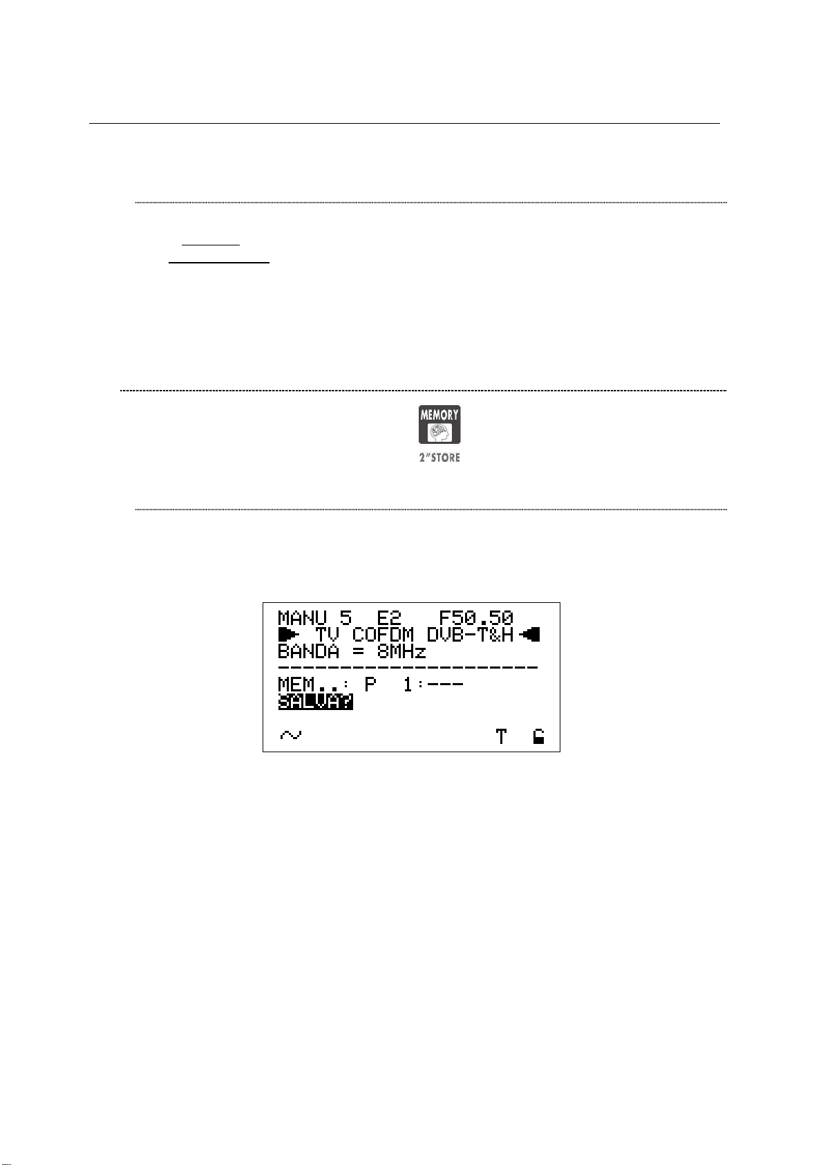
TECHNIPLUS / TECHNIPLUS HD
USER MANUAL
SEEK&STORE (SCAN) START
Using the Standard Navigation Mode, highlight the display bottom row.
If START? appears a brand new memory plan will be stored. Should
OVERWRITE? appear, the selected target Automemory plan already contains
data, and will be overwritten without further notice.
Press the encoder [C] knob once and the auto seek & store will start. The display
will also give information on the status of the research. When finished, the total
number of both analogue and digital found and stored channels will be displayed.
15.2 MANUALLY CREATING A MEMORY PLAN: MANUMEMORY
Press and release the MANUMEMORY [9] key.
CREATE A BRAND NEW MEMORY PLAN
Using the Standard Navigation Mode, highlight the MANUxx item of the LCD
display top row on the left and select the desired target memory plan. When the
current target plan is void, the LCD row under the dotted line bottom row displays
MEM P1: ---.
• Select a void memory plan (the LCD row under the dotted line bottom row
displays MEM P1: ---)
• Using the Standard Navigation Mode, highlight the channel ID item in the first
row of the LCD display. Then select the channel ID to be stored into the target
memory plan.
• Using the Standard Navigation Mode, highlight the SAVE? item.
• Press the encoder knob. The selected channel will be stored.
To add further channels to the current memory plan:
• Using the Standard Navigation Mode, highlight the channel ID item in the first
row of the LCD display. Then select the new channel ID to be stored.
• Using the Standard Navigation Mode, highlight the MEM..:P item, and select a
void memory position (the LCD row under the dotted line will displays, e.g.
MEM: P 5: ---).
• Highlight the SAVE? item.
• Press the knob. The selected channel has now been stored.
Press once and release the MEAS [4] key to quit the memory menu.
50
Page 71

TECHNIPLUS / TECHNIPLUS HD
USER MANUAL
ADDING A FURTHER CHANNEL TO AN EXISTING MEMORY PLAN
Using the Standard navigation Mode, highlight the MANUxx item in the LCD top
row on the left, then select the desired target memory plan (in which a new
channel has to be added). Then:
• Using the Standard navigation Mode, highlight the channel ID item on the first
row of the display and select a new channel ID to be stored.
• Highlight the MEM..:P item, and select a void memory position (the first LCD
row under the dotted line displays, e.g., MEM: P 6: ---).
• Highlight the SAVE? Item and press the encoder knob. The selected channel
ID has now been stored.
Further channels may be added by repeating the above steps.
Press once and release the MEAS [4] key to quit this menu.
ADDING A FURTHER CHANNEL TO A MEMORY PLAN CURRENTLY IN
USE
When the channel ID to be added to the memory plan in use is already correctly
tuned (proceed as described in Chapter 10 SIGNAL TUNING: PLAN at page 21),
press and hold for 2’’ the MANUMEMORY [9] key.
The tuned channel will be automatically stored in the first void position of the
current memory plan. The LCD [B] will display:
Press and release the MEAS [4] key to quit this menu.
15.3 DELETING A MEMORY PLAN
Press and hold for 2” the VOLUME [R] key. Using the Standard navigation Mode,
highlight the FILE MANAGER item, then press the encoder knob [C] to enter the
configuration menu.
THE MEMORY PLAN CURRENTLY IN USE CANNOT BE DELETED.
To change the memory plan currently in use, proceed as described in Chapter 10
SIGNAL TUNING: PLAN at page 21.
DELETING AN AUTOMEMORY CHANNEL PLAN
Using the Standard navigation Mode, highlight the SELECT TYPE item and select
AUTOSCAN.
51
Page 72

• Using the Standard navigation Mode, highlight SELECT FILE and select the
memory plan to be deleted (AUTO 1, AUTO 2, …).
• Highlight the item DELETE FILE and press the encoder knob [C] to
permanently delete the above selected memory plan.
The meter will confirm the selected plan has been deleted (DELETED!). The
warning message VOIDED! means you have tried to delete a permanent and not
erasable memory plan (e.g.: ITALY).
TECHNIPLUS / TECHNIPLUS HD
USER MANUAL
DELETING A MANUAL MEMORY CHANNEL PLAN
Using the Standard navigation Mode, highlight the item SELECT TYPE, then
select the item PLAN.
• Highlight the item SELECT FILE and select the memory plan to be deleted
(MANU1, MANU2, …).
• Highlight the item DELETE FILE and press the encoder knob [C] to
permanently delete the above selected memory plan.
The meter will confirm the selected plan has been deleted (DELETED!). The
warning message VOIDED! means you have tried to delete a permanent and not
erasable memory plan (e.g.: ITALY).
52
Page 73

TECHNIPLUS / TECHNIPLUS HD
USER MANUAL
16 TV AND COFDM AUTO MEAS&STORE (DATA LOGGER)
The meter can automatically tune all of the channels included in any memory plan
(whichever the type) and automatically perform all the available measurements on
each of the tuned channels. The measurements results are stored into a user selected
target file (LOGGER files).
Any LOGGER file can be downloaded to a PC in MS Excel ® format using the
connection software Technisat TECHNITOOL.
The meter is capable to store up to 99 different LOGGER files, thus allowing the user
to perform a complete auto Meas&Store at almost every end-user socket in a building,
and to archive the results only when back home, without any need to stop the field
activity to free memory space for allowing further measurements.
16.1 AUTO MEAS&STORE
Press once and release the SAVE [U] key; the LCD will display:
In the second row from the top [PLAN], the LCD will display the group of channels
(Memory Plan) whose channels will be automatically tuned to perform the Auto
Meas&Store feature. Country Memory Plans (e.g.: ITALY) cannot be selected for
Auto Meas&Store.
Using the Standard Navigation Mode, highlight the item PLAN and select the Memory
Plan on which the Auto Meas&Store will be performed.
Please be careful not to select a Memory Plan including Satellite Transponders.
For TV signals, only user defined memory plans (Manual Memory or AutoMemory)
can be selected.
Into the LCD third row from the top the current target LOGGER file [DataFile] is
displayed. Into this LOGGER file the measurement data will be stored. To edit the
target LOGGER file, using the Standard Navigation Mode highlight the item DataFile
and select the desired target file. Target LOGGER file names can be selected from
LOG.1 to LOG.99.
In case the current target Logger file is void, the LCD bottom row will display
STORE? In case the current target Logger file already contains data from a previous
Auto Meas&Store, the LCD bottom row will display OVERWRITE? In this case,
should you proceed to a new Meas&Store, the former data will be deleted without
further notice.
53
Page 74

TECHNIPLUS / TECHNIPLUS HD
USER MANUAL
To start the auto Meas&Store, using the Standard Navigation Mode, highlight the item
SAVE? or, resp., OVERWRITE? and press the encoder knob [C]. In the lowest part of
the LCD a progress bar will display the status of the running Meas&Store as well as
the message WAIT!. When the auto Meas&Store is completed the LCD will display
STORED!
16.2 RECALL A PREVIOUSLY STORED LOGGER MEMORY PLAN
The meter allows the user to recall the required measurement files (LOGGER type)
and display all the measurement previously performed and stored.
Press once and release the RECALL [6] key. The LCD [B] will be display:
The second row from the top [DataFile] of the display shows the LOGGER file which
will be recalled. To select the desired file, using the Standard Navigation Mode
highlight the item DataFile and select the required LOGGER file.
The meter will let you select only previously created files. If the LOG.45 is void, i.e. no
automatic measurements have been ever stored, the meter will not allow you to
select this file.
When the required DataFile has been chosen, highlight the item RECALL and press
the encoder knob [C]. The LCD will display a resume screen showing the stored
measurement data for each channel:
The LCD will report (from the left): the channel ID, channel type, channel level
(analogue signal) or power (digital signal) and the quality test results.
Rotate the encoder to scroll (up or down) the complete channel list.
Press once and release the MEAS [4] key to quit the menu.
54
Page 75

TECHNIPLUS / TECHNIPLUS HD
USER MANUAL
NOTES
_____________________________________________
_____________________________________________
_____________________________________________
_____________________________________________
_____________________________________________
_____________________________________________
_____________________________________________
_____________________________________________
_____________________________________________
_____________________________________________
_____________________________________________
_____________________________________________
_____________________________________________
_____________________________________________
_____________________________________________
55
Page 76

TECHNIPLUS / TECHNIPLUS HD
USER MANUAL
SATELLITE SIGNAL ANALYZER
17 SATELLITE DISH ALIGNMENT
17.1 DISH ALIGNMENT TO A SPECIFIC SATELLITE WITH
AUTOMATIC SATELLITE IDENTIFICATION: (SAT FINDER)
The meter can assist you in aligning the satellite dish to a specific satellite. Just
mount and briefly align the dish to the desired satellite. The meter can detect if you
are really pointing to the desired satellite by looking for three user-defined reference
transponders within any received satellite signal, then it can support you in finealigning the dish.
Set up the desired satellite (refer to Chapter 18 METER CONFIGURATION : PLAN at
page 61, and above all to Chapter 18.1 EXPLORING ALL THE TRANSPONDERS
OF A SATELLITE at page 61) or a Transponder Memory Plan including one or more
transponders carried by the desired satellite (Refer to Chapter 18 METER
CONFIGURATION : PLAN at page 61, and above all to paragraph 18.3 NAVIGATE
THE SOLE TRANSPONDERS INCLUDED IN A USER DEFINED TRANSPONDER
MEMORY PLAN. at page 63).
Press once and release the SAT FINDER [T] key. The LCD will display (this
screenshot is related to EUTELSAT 7E satellite):
If the displayed transponders do not match with the appropriate ones, using the
Standard Navigation Mode highlight the transponder name to be modified, and select
the required transponder.
In case you wish to indicate less than three reference transponders, just set up the
one or the two reference ones you like, and set into the unused field(s) the reference
transponder set up as the first one.
Then highlight the item START? and press the encoder knob [C] to activate the SAT
FINDER function.
During the identification process, the START icon will be replaced by the item
SATLOOKING and a rotating bar will be displayed as an “in progress” indicator.
When the satellite will be correctly found, the meter will start the buzzer (refer to
Chapter 17.4 ANTENNA POINTING AID: BUZZER at page 59) . The Noise Margin
value (also displayed on a level bar with peak level) and the Quality Test results will
be displayed on the LCD:
56
Page 77

TECHNIPLUS / TECHNIPLUS HD
Proceed to fine align the dish until the level bar will be to its peak. The buzzer sound
will also help you while performing this fine-alignment.
17.2 “DUAL FEED” DISH ALIGNMENT
The meter allows the alignment of Dual LNB satellite dishes by performing
simultaneous measurements on both LNB, with no need to continuously switch
between RF cables and to set different frequencies.
DiSEqC SWITCH
USER MANUAL
Before performing Dual Feed measurements, connect the two RF cables from the
two LNBs to a DiSEqC switch (a suitable DiSEqC switch is included in the meter
accessories).
SATELLITE DISH POINTING AND FINE ALIGNMENT
Press and hold for at least 2” the S.C.R. LNB [S] key. The LCD will display:
LNB 1: SATELLITE SETUP
Using the Standard navigation Mode, select the satellite (satellite name) or the
Transponder Memory Plan (PLAN) to which the LNB1 has to be aligned.
Right to the satellite name or, resp. the Transponder Memory Plan, the reference
transponder for the LNB1 alignment is displayed.
If required, use the Standard Navigation Mode to select a different reference
transponder .
57
Page 78

LNB 2: SATELLITE SETUP.
Using the Standard navigation Mode, select the satellite (satellite name) or the
Transponder Memory Plan (PLAN) to which the LNB2 has to be aligned.
Right to the satellite name or, resp. the Transponder Memory Plan, the reference
transponder for the LNB2 alignment is displayed.
If required, use the Standard Navigation Mode to select a different reference
transponder.
DISH ALIGNMENT & FINE DISH ALIGNMENT
Once selected the desired satellites, the LCD will display the Noise Margin and
the Quality Test results (FAIL, MARGIN, PASS) for each LNB. Each Noise
Margin value (LNB1 and LNB2) will be also displayed on a level bar with peak
level memory.
Move the antenna dish till you get the maximum Noise Margin value on both
LNB at the same time. The peak level memory of each level bar displays a
vertical bar showing the maximum Noise Margin level reached by the relevant
LNB while pointing.
In some cases it won’t be possible to maximize the Noise Margin value for both
LNBs, depending on the signal receiving conditions. In this case the antenna
should be set to get the best compromise between the Noise Margin value of the
two LNBs.
Press once and release the MEAS [4] key to quit this function.
TECHNIPLUS / TECHNIPLUS HD
USER MANUAL
17.3 POINTING AND MOVING A MOTORIZED DISH (DiSEqC
MOTOR)
Select the satellite (proceed as described in Chapter 18.1 EXPLORING ALL THE
TRANSPONDERS OF A SATELLITE at page 61) or the transponder included in the
satellite to which the antenna must be aligned (refer to the paragraph 18.2
MANUALLY TUNING THE TRANSPONDER at page 62).
Press once and release the DiSEqC MOTOR [U] key. The LCD will display:
58
Page 79

The LCD third row from the top displays (left to right): the selected satellite name (or
the Transponder Channel Plan), the selected transponder and the relevant frequency
value.
The LCD bottom rows display (bottom to top, left to right): the name of the selected
bouquet, the encryption system in use, the Noise Margin value (also displayed on the
level bar with peak memory level), and the result of the Quality Test.
In the previous screenshot, the ACT.: item is highlighted: this item indicates the
command which will be sent to the motorized antenna.
Using the Standard Navigation Mode, select one of the 4 available commands:
MOVE
GOTO
TECHNIPLUS / TECHNIPLUS HD
USER MANUAL
This command moves the antenna to the direction mentioned in the DIR item
(EAST o WEST).
Select the movement direction. The measurement values reported by the meter
before the satellite or the transponder identification (while the dish is moving) have
to be neglected.
This command selects one of the 99 pre-stored antenna positions.
Highlight the item POS.: and select the required pre-stored position, then
highlight the item APPLY? and press the encoder knob [C] to send the command
to the dish.
STORE
This command allows to store the current motor position. Up to 99 different
antenna positions can be stored in the meter (POS.: 1 to 99).
Highlight the item POS.:. and select the memory location where the current
antenna position will be stored.
Highlight the item STORE?. and press the encoder knob [C] to confirm.
RESET
In case some no-go zones (banned sectors) were previously set up on the
concerned motor antenna system, this command removes any previously set
limitation.
Highlight the item APPLY? and press the encoder knob [C] to reset any banned
sector.
17.4 ANTENNA POINTING AID: BUZZER
Press and hold for 2” the HELP [7] key.
You can hear a beep whose duty cycle is proportional to the signal Noise Margin.
This is a dish alignment aid feature: when the satellite transponder is locked (satellite
is found) the meter will start the Buzzer and at the same time the LCD will display:
59
Page 80

The LCD second row displays (left to right) the selected Satellite or the selected
Transponder Memory Plan, the currently tuned transponder and the relevant
frequency value. The frequency value can be modified using the encoder [C].
The two bottom rows display the Noise Margin measurement (also on a level bar with
peak memory function) and the Quality Test result.
Press any key to quit this function.
WARNING: the buzzer function is active with digital signals ONLY.
TECHNIPLUS / TECHNIPLUS HD
USER MANUAL
60
Page 81

TECHNIPLUS / TECHNIPLUS HD
USER MANUAL
18 METER CONFIGURATION : PLAN
Connect the coax cable to the connector F [S1] on the meter.
Press once and release the PLAN [1] key.
18.1 EXPLORING ALL THE TRANSPONDERS OF A SATELLITE
Using the Standard Navigation Mode, highlight the item SATELLITE and select the
required satellite.
Press once and release the MEAS [4] key.
The LCD first row displays (left to right) the selected satellite, the transponder and the
relevant frequency value.
CHANGING THE SATELLITE
Press once and release the PLAN [1] key. Highlight the item SATELLITE and select
the desired satellite. Press once and release the MEAS [4] key to return to the current
measurement screen.
CHANGE THE TRANSPONDER
Highlight the transponder currently in use. Select the required transponder. Each
encoder step moves the transponder one step forward or backward. To speed up the
surfing, rotate the encoder quickly.
61
Page 82

TECHNIPLUS / TECHNIPLUS HD
USER MANUAL
MANUALLY CHANGE THE FREQUENCY VALUE
Should you need to manually change the frequency value, highlight the frequency
item and setup the desired frequency value.
Each encoder step increase or decrease the frequency value by 0,1 MHz.
To speed up the surfing, rotate the encoder quickly.
18.2 MANUALLY TUNING THE TRANSPONDER
ALL THE TRANSPONDER DISTINCTIVE PARAMETERS MUST BE KNOWN.
Select a Transponder Memory Plan (refer to Chapter 18.3 NAVIGATE THE SOLE
TRANSPONDERS INCLUDED IN A USER DEFINED TRANSPONDER MEMORY
PLAN. at page 63).
Starting from any measurement screen, repeatedly Press once and release the
MEAS [4] to highlight the level measurement screen (analogue signals) or the
power measurement (digital signals).
Using the Standard Navigation Mode, highlight the display second row (the signal
type to be tuned).
WARNING: the frequency value is the last item to be modified.
Select the required signal type to be tuned (SAT ANALOG, SAT QPSK DVB-S, SAT
QPSK DSS).
IT MIGHT BE NECESSARY TO GO BACK TO THE LEVEL/POWER
MEASUREMENT SCREEN (REPEATEDLY PRESS THE MEAS KEY) TO
COMPLETE THE SIGNAL TYPE SELECTION. THE SIGNAL TYPE CANNOT BE
MODIFIED IN OTHER MEASUREMENT SCREENS.
Highlight the item LNB and set the required polarization and the high/low band.
Highlight the item DiSEqC and set the required value.
62
Page 83

TECHNIPLUS / TECHNIPLUS HD
USER MANUAL
Highlight the item L.O. and select the required frequency value. To speed up the
surfing, rotate the encoder quickly.
Highlight the item S.R. (Symbol Rate) and select the required value. To speed up the
surfing, rotate the encoder quickly.
Highlight the frequency value item and select the required value. To speed up the
surfing, rotate the encoder quickly.
Press once and release the HELP [7] key to start the automatic tuning of the selected
transponder. While processing, the following screen will be displayed:
When completed, the LCD will display:
18.3 NAVIGATE THE SOLE TRANSPONDERS INCLUDED IN A
USER DEFINED TRANSPONDER MEMORY PLAN.
To create a Transponder Memory Plan, refer to the Chapter 22 CREATING A
TRANSPONDER MEMORY PLAN at page 74.
A Transponder Memory Plan can contain transponders from different satellites.
Highlight the item MANUAL MEMORY and select the required Transponder Memory
Plan (MANU…).
Press once and release the MEAS [4] key.
63
Page 84

TECHNIPLUS / TECHNIPLUS HD
USER MANUAL
The LCD first row displays (left to right) the selected Transponder Memory Plan, the
transponder currently in use, the relevant frequency value.
SELECT THE REQUIRED TRANSPONDER
Highlight the currently tuned transponder and select the required transponder. Each
encoder step selects the previous or the next transponder. To speed up the surfing,
rotate the encoder quickly.
ONLY A TRANSPONDER INCLUDED IN THE SELECTED TRANSPONDER
MEMORY PLAN CAN BE SELECTED.
MANUALLY MODIFY THE FREQUENCY VALUE
Should you need to manually modify the frequency value, highlight the current
frequency value item. Each encoder step increase or decrease the frequency value
by 0,1 MHz. To speed up the surfing, rotate the encoder quickly.
MODIFY THE TRANSPONDERS GROUP TO BE EXPLORED
The transponders group can be modified only from the main screen. Press once and
release the PLAN [1] key and select the item MANUAL MEMORY to enter the main
screen.
WARNING: After showing the user defined Transponder Memory Plans, the
meter will display the pre-stored groups of transponder (refer to Chapter 18.1
EXPLORING ALL THE TRANSPONDERS OF A SATELLITE at page 61)
64
Page 85

TECHNIPLUS / TECHNIPLUS HD
USER MANUAL
NOTES
_____________________________________________
_____________________________________________
_____________________________________________
_____________________________________________
_____________________________________________
_____________________________________________
_____________________________________________
_____________________________________________
_____________________________________________
_____________________________________________
_____________________________________________
_____________________________________________
_____________________________________________
_____________________________________________
_____________________________________________
65
Page 86

TECHNIPLUS / TECHNIPLUS HD
USER MANUAL
19 PERFORMING MEASURES: MEAS
The TECHNIPLUS is equipped with both one TFT [A] display and one LCD [B] display.
The use of the sole LCD [C] display extends the battery operating time.
On the other side, through the TFT [A] display the user can easily evaluate the tuned signal
and the relevant quality; at the same time, all the measurement values can be displayed on a
color TFT screen; their reading is immediate and intuitive, also under direct sunlight and in
any weather condition.
Press and hold for 2’’ the MPEG PICT [5] key to activate or switch off the TFT [A]
display
19.1 ANALOGUE TRANSPONDERS
The meter cannot demodulate satellite analogue signals.
VIDEO SIGNAL PEAK LEVEL MEASUREMENT
The LCD bottom row shows the current video signal peak level together with the
relevant measurement unit. The video signal peak level real time value is also displayed
on a level bar with peak level memory.
SPECTRUM ANALYSIS OF THE TUNED CHANNEL
Refer to Chapter 20 SPECTRUM ANALYZER MODE at page 71.
66 66 bis
Page 87

TECHNIPLUS / TECHNIPLUS HD
USER MANUAL
In the next pages each meter function, as well as any measurement feature, will be
described with a simultaneous reference to both the TFT display and the LDC one. The left
pages refer to the TFT [A] screen, the right ones refer to the LCD [B] screen.
Refer to the Chapter 10 SIGNAL TUNING: PLAN at page 21 to tune the desired channel.
The LCD second row shows the item SAT ANALOG.
On the next rows :
• Polarization and high/low band (third row, on the left)
• DiSEqC status (third, on the right)
• Local Oscillator frequency (fourth row, on the right)
are displayed. The LCD bottom row displays on the left the power supplied to the antenna
LNB ; on the right, a “S” icon and a black filled quadrangle are displayed in correspondence
to the items SAT and AN.
The level bar displays a vertical bar showing the maximum level (peak level) reached by
signal during the measurements.
Page 88

TECHNIPLUS / TECHNIPLUS HD
USER MANUAL
19.2 DIGITAL TRANSPONDER
The TFT [A] will display: The LCD will display:
CHANNEL POWER MEASUREMENT
Press once and release the ZOOM TFT [3] key to activate the measurement parameters
on the TFT display.
67 67 bis
Page 89

TECHNIPLUS / TECHNIPLUS HD
USER MANUAL
The LCD second row displays the standard of the tuned signal (SAT QPSK DVB-S or SAT
QPSK DSS).
The LCD bottom row displays the main information of the relevant bouquet:
• Bouquet name (network name), after some seconds and under acceptable receiving
conditions.
• Orbital position of the detected satellite.
• Encryption system (encrypt), if there is at least one encrypted program in the
bouquet, after some seconds and in acceptable receiving conditions.
• An S icon in correspondence with the SAT icon on the LCD frame
• A lock in correspondence with the DIG icon on the LCD frame. The lock is closed
when the received signal has been correctly locked, otherwise it appears open.
Press and release the MEAS [4] key up to display the following screen:
The LCD second row displays the items SAT QPSK DVB-S or SAT QPSK DSS.
In the next rows, the:
• Polarization and high/low band (third row on the left)
• DiSEqC status (third row on the right)
• Local oscillator frequency (fourth row on the left)
• Symbol Rate (fourth row on the right)
information are displayed on the screen. On the LCD bottom right corner, the icon “S” and a
open lock will be displayed in correspondence with SAT and “DIG” respectively.
Page 90

TECHNIPLUS / TECHNIPLUS HD
USER MANUAL
NOISE MARGIN, QUALITY TEST, MER AND EVM MEASUREMENTS
From the previous measurement screen, press once and release the MEAS [4] key.
The TFT displays a resuming table showing all the required parameters to correctly point
the antenna, to show the quality of the detected signal (Noise Margin, MER, bBER,
aBER, EVM, Channel Power) and to recognize the main features of the signal (L.O.
frequency, polarization and high/low band, DISEqC status, AFC and FEC values, quality
test results). The demodulated video signal is displayed as a background.
In the next measurement step the above resuming table will still be displayed.
68 68 bis
Page 91

TECHNIPLUS / TECHNIPLUS HD
USER MANUAL
WHILE PERFORMING SUCH MEASUREMENTS, THE LOCK DISPLAYED AT BOTTOM
RIGHT SIDE OF THE SCREEN WILL BE OPEN. THIS IS BECAUSE THE METER
EXPLORES THE WHOLE CHANNEL BAND IN ORDER TO DETECT THE TRUE
CHANNEL POWER.
The LCD bottom row displays the power of the detected signal together with the relevant
measurement unit.
The real time video signal peak level value is displayed also on a level bar with peak level
memory: a vertical bar is showing the maximum level (peak level) reached by signal during
the measurements.
In case the signal is properly locked, the LCD displays the Noise Margin (Noise Margin,
N.MAR), quality test (QLTY), MER and EVM measurements.
The Noise Margin and MER values are also displayed on a level bar with peak level
memory.
Furthermore, the bottom row of the screen displays the main information of the relevant
bouquet:
• Bouquet name (network name), after some seconds and under acceptable
receiving conditions.
• Orbital position of the detected satellite.
• Encryption system (encrypt), if there is at least one encrypted program in the
bouquet, after some seconds and under acceptable receiving conditions.
• An S icon, in correspondence with the SAT icon on the LCD frame
• A lock in correspondence with the DIG icon on the LCD frame. The lock is closed
when the received signal has been correctly locked, otherwise it appears open.
Page 92

TECHNIPLUS / TECHNIPLUS HD
USER MANUAL
BER MEASUREMENTS BEFORE AND AFTER VITERBI ERROR CORRECTION
From the previous measurement screen, press once and release the MEAS [4] key. The
BER before Viterbi error correction (appointed as bBER or preBER) and the BER after
Viterbi error correction (appointed as aBER or posBER) parameters will be displayed.
FEC AND BOUQUET MAIN DATA
Form the previous measurement screen, press once and release the MEAS [4] key.
The FEC value of the selected bouquet will be displayed.
69 69 bis
Page 93

TECHNIPLUS / TECHNIPLUS HD
USER MANUAL
The measurements are also displayed on a level bar with peak level memory.
In case the tuned bouquet contains the relevant information, the LCD will display:
• the network name (NETW. NAME)
• the bouquet name (BOUQ. NAME)
• the current date (DATE), as stated in the bouquet itself
Any information missing (not included in the bouquet) will result in a blank field. Anyway, the
signal is properly locked even when one or all of said information is missing provided that
the lock at the LCD bottom right corner is closed.
Page 94

TECHNIPLUS / TECHNIPLUS HD
USER MANUAL
Press once and release the MEAS [4] key repeatedly to cyclically display the above
mentioned measurement screen.
DISPLAYING THE SERVICE LIST OF THE CURRENT BOUQUET
Press once and release the MPEG PICT [5] key.
SPECTRUM ANALYZER MODE
Refer to Chapter 20.
70 70 bis
Page 95

TECHNIPLUS / TECHNIPLUS HD
USER MANUAL
Press once and release the HOME [Z] key to directly switch to the level / channel
power measurements.
The following information will be displayed: the full program list of the currently tuned
bouquet, the relevant video (Vpid) and audio (Apid) PIDs and the encryption status key (Y=
encrypted, N= not encrypted/free to air). It might take a few second to get the full
information displayed.
Rotate the encoder [C] to scroll down the program list (up to 64). The highlighted program
will be displayed on the TFT screen and the sound will be played through the meter built-in
loudspeaker.
Press MEAS [4] key to go back to the previous screen.
Page 96

TECHNIPLUS / TECHNIPLUS HD
USER MANUAL
20 SPECTRUM ANALYZER MODE
Press once and release the SPECT [2] key. The spectrum of the tuned signal will be
displayed.
71 71 bis
Page 97

TECHNIPLUS / TECHNIPLUS HD
USER MANUAL
The relevant level or channel power is displayed in the LCD bottom row next to the item
MRK, together with the relevant measurement unit.
Page 98

TECHNIPLUS / TECHNIPLUS HD
USER MANUAL
20.1 MODIFY/CHANGE THE TRANSPONDER
Using the Standard Navigation Mode, highlight the transponder item and select the
desired transponder.
WARNING: only the transponder in the selected Satellite or Memory Plan can
be selected. Refer to the Chapter 18 METER CONFIGURATION: PLAN at page
58 to change the selected Satellite or Transponder Memory Plan.
20.2 MOVING THE MARKER (FREQUENCY VALUE)
Using the Standard Navigation Mode, highlight the frequency value and move the
marker. The relevant level/channel power value will be displayed on the bottom row
on the left (MRK).
While pointing the antenna, the meter might detect the transponder pattern of an
unidentified satellite. Press once and release the HELP [7] key to tune the relevant
signal (refer to Chapter 18.2 MANUALLY TUNING THE TRANSPONDER at page
62).
20.3 EDITING THE LEVEL END OF SCALE
Highlight the top level (end of scale) value on the y-axis and rotate the encoder [C] to
increase or decrease the end of scale value.
20.4 EDITING THE SPAN VALUE
Highlight the span (SP…) value and set the desired one.
Only the pre-defined span values (from 50 MHz to FULL) can be set. No fine
adjustment is possibile.
20.5 ACTIVATE THE MAX HOLD FUNCTION
Press once and release the SPECT [2] key again.
The MaxH icon will be displayed on the display bottom row in correspondence with
the “ENCRYPT” item on the right edge of the display.
Press once and release the SPECT [2] key again to quit the MaxHold function.
72
Page 99

TECHNIPLUS / TECHNIPLUS HD
USER MANUAL
21 SATELLITE AUTO MEAS&STORE (DATA LOGGER)
This meter can automatically tune all of the transponder of a specific satellite, or
included in any Transponder Memory Plan (whichever the type), and to automatically
perform all the available measurements on each of the tuned transponders. The
measurements results are stored into a user selected target file (LOGGER files).
Any LOGGER file can be downloaded to a PC in MS Excel ® format using the
connection software Technisat TECHNITOOL.
The meter is capable to store up to 99 different LOGGER files, thus allowing the user
to perform a complete auto Meas&Store at almost every end-user socket in a building,
and to archive the results only when back home, without any need to stop the field
activity to free memory space for allowing further measurements.
21.1 AUTO MEAS&STORE
Refer to the Chapter 16.1 AUTO MEAS&STORE at page 53
21.2 RECALL A PREVIOUSLY STORED LOGGER MEMORY PLAN
Refer to the Chapter 16.2 RECALL A PREVIOUSLY STORED LOGGER MEMORY
PLAN at page 54.
21.3 DELETING A MEMORY PLAN
Refer to Chapter 22.3 DELETING A MEMORY PLAN at page 75 to delete the
useless files.
73
Page 100

TECHNIPLUS / TECHNIPLUS HD
USER MANUAL
MEMORY FEATURES FOR SATELLITE SIGNALS
22 CREATING A TRANSPONDER MEMORY PLAN
22.1 MANUALLY CREATING A TRANSPONDER MEMORY PLAN:
MANUMEMORY
Press and release the MANUMEMORY [9] key.
CREATE A BRAND NEW MEMORY PLAN
Using the Standard navigation Mode, highlight the MANUxx item in the LCD top
left corner. Select the memory plan to be created (target memory plan). When the
current target memory plan is void, the LCD displays (top row, right to the
MANUxx item) PR 1; otherwise, a number greater than 1 will appear to the right
hand-side of item PR.
Using the Standard Navigation Mode, highlight the MANUxx item and then select a
void memory plan.
• Highlight the signal type item displayed on the LCD second row (analogue,
digital DVB-S, digital DSS) and select the required signal type. Then proceed
in the same way with the LNB high/low band and polarization, DISEqC, Local
oscillator (L.O.) and Symbol rate (SR).
• Highlight the frequency value displayed on the LCD top right corner, and select
the desired value. Rotate the encoder [C] quickly to speed up the frequency
surfing.
• Highlight the item STORE? AND press the encoder knob [C] to store the
selected transponder.
To add further transponders to the memory plan, highlight the signal type icon and
proceed as described above.
Press once and release the MEAS [4] key to quit this function.
ADDING A FURTHER TRANSPONDER TO AN EXISTING MEMORY PLAN
Using the Standard Navigation Mode, highlight the MANUxx item (MANU 1, MANU
2, …) in the LCD top left corner, and select the desired memory plan. On the right
74
 Loading...