

Page 1
Installation Manual
Wall Mounting
DigiDish 33
DigiDish 45
EN
FR IT NL CZ PL
Satman 33
Satman 45
Multytenne 45
Page 2
Dear customer,
EN
thank you for purchasing one of the quality products produced by TechniSat. In order to ensure that the
quality of the product remains constant over many years, both the dish and the mounting bracket are
made of aluminium. Please read the installation instructions carefully befor4e proceeding with the installation, to ensure that you can enjoy optimum reception performance after installation. Before starting the
installation, please check that you have received all parts and components of the external unit.
FR ITNLCZPL
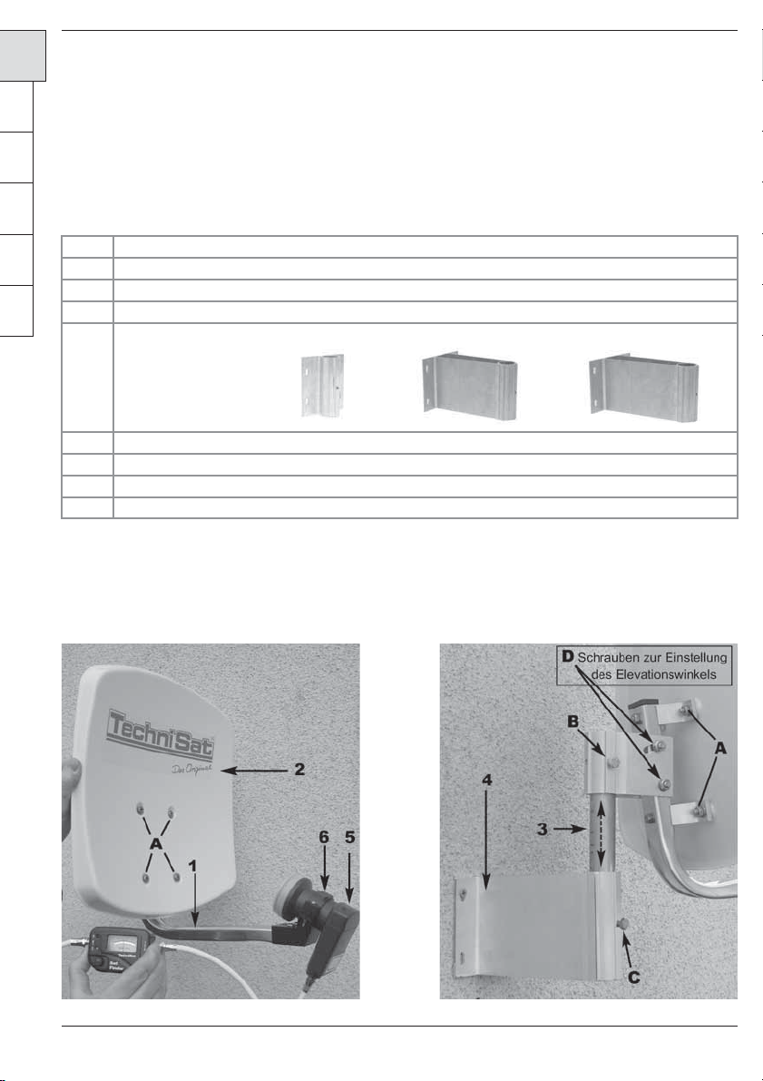
Items supplied (see illustrations 1 and 2)
Item Article
1 AZ/EL bracket with LNB holding bracket and swivel profile
2 Dish antenna
3 Connector
4 Wall mount*: “short” or “medium” or “long”
5 LNB
6 LNB holding bracket with 2 screws M3x30, 2 nuts M3, 2 washers**
A Screws M6x15, 4 nuts M6, 4 washers
D Screws for the adjustment of the elevation angle
* Contents vary with package selected
**only with DigiDish
Illustration 1 Illustration 2
2Operating manual
Page 3
1 Mounting the external unit
When you unpack the external unit, you will find that it has already been partly pre-assembled, so all
you need to do is to mount the dish (item 2) and the connector piece (item 3). First, use the screws (A)
to attach the dish to the AZ/EL bracket (item 1). Then loosen the screw (B) on the swivel profile in order
to mount the connector piece. Then mount the LNB (item 5) on the LNB holder, using the LNB holding
bracket (item 6) as shown in illustration 1.
2 Installation
Selecting a location
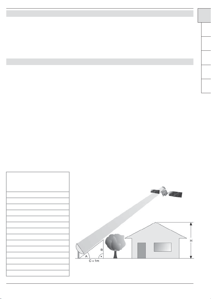
a) First ensure there is an uninterrupted line of sight from the intended mounting position in a south-
erly direction in order to receive signals from the satellite position ASTRA 19,2° East. With the
aid of the illustration below you can see whether you have left enough space with regard to any
neighbouring obstruction, in order to avoid the signal being weakened by such an obstruction.
When mounting the dish below a terrace, please ensure that it is not in the shadow of a projecting roof.
b) Now attach the wall mount (item 4) horizontally at the location selected. In order to ensure an
optimum hold fort he external unit, you should select appropriate fastening materials (dowels,
screws, etc.). Because of the huge variety of wall conditions found in practice, no fastening materials for mounting he wall mount is supplied with the package.
c) Loosen the screw (C) on the wall mount, and attach the external unit using the connector piece.
EN
FR IT NL CZ PL
Angle A Gradient B
(elevation) (cm per m)
22° 40,40
24° 44,52
26° 48,77
28° 53,17
29° 55,40
30° 57,74
31° 60,00
32° 62,49
33° 64,90
34° 67,45
35° 70,02
36° 72,65
37° 75,36
38° 78,13
3 Multytenne
Page 4

3 Safety notes
EN
When installing the unit, please conform with the various European standards and VDE regulations relating to the safety of electrical appliances and installations (e.g. VDE 0855, Part1). When in doubt, consult
your retailer.
FR ITNLCZPL
4. Mounting the F-connectors
Note!
Attach the F-connectors while the receiving installation is disconnected from main power!
Please proceed with extreme care when installing the F-connectors, in order to avoid any functional
problems or even the destruction of the satellite receiver, which can result from incorrectly mounted connectors. In addition to the text, please also see illustration 3.
• Use a sharp knife to remove approximately 6 mm of the insulation at the end of the cable, cutting
down to the core cable. Please be careful not do damage the core cable.
• Remove the extraneous section of shielding mesh.
• Now remove 10 mm of the outer plastic mantle, in order to expose the wire mesh. Please ensure
that the wire mesh is not damaged.
• Ensure that no wires of the shielding mesh are in contact with the core cable.
• Now twist the F-connector carefully on to the cable, until the core cable is level with the front
rim of the F-connector. Then check once more that the wire mesh is not in contact with the core
cable. The F-connector is now correctly mounted.
Screw-on F-connector
Exposed wire
wire mesh
Silver foil
5. Positioning the external unit
The positioning of the external unit should preferably be done with the aid of a calibration tool. Alternatively, positioning can also be effected with the aid of the less expensive TechniSat SatFinder (Article No.
0000/3045). If neither of these aids is available, positioning can be carried out as follows, using a digital
receiver and a television set.
1. Use a suitable co-axial cable to connect the LNB to the receiver.
2. Connect the receiver to the television set, and set the receiver to a programme slot on which a
programme of the desired satellite can be received.
3. Consult an AZ/EL table to determine the elevation angle for your location. For Example, the angle
fort he ASTRA 19,2° East satellite in the German town of Daun is 31,29°. As your external unit
incorporates an offset dish, the angle of elevation to be set is not the angle in the table, but an
adjusted angle which is calculated for the specific dish used. This is calculated as follows
Angle of Elevation – Offset angle = Angle to be set
4Operating manual
Page 5

The offset angle of the DigiDish 33 resp. the DigiDish 45 is 30°.
Therefore, if you are in Daun and using a DigiDish 33 resp. 45, this results in an angle of:
31,29° - 30° = 1,29°
4. Loosen the screws (D) on the swivel profile so that you can move the external unit up or down.
Place a rod or plank over the dish as shown in Illustration 4. Now use a protractor to set the angle
calculated.
Illustration 4
Board/rod
5. Now loosen the screw (C) resp. (B) on the swivel profile, and slowly turn the dish in an easterly or
westerly direction (angle of azimuth), until you receive the television picture via the receiver.
6. Some fine-tuning of the dish is now still required. Ideally, you should call up the transponder
information (see operating manual of the digital receiver).
7. Now carefully adjust the azimuth (East/West) angle as well as the angle of elevation so that the
indicator for signal strength resp. quality is at a maximum level.
8. Now tighten all screws, and take care to note that reception does not deteriorate. The dish is now
completely mounted, and has an optimum position fort he reception of the desired satellite.
EN
FR IT NL CZ PL
Mounting advice
Multytenne LNB
Art. No. 0000/8810
Dear customer,
Your Multytenne LNB ist designed for use with the SATMAN 45 satellite dish antenna. With this, you can
receive the digital programmes of 4 orbital positions while located in Germany. Reception in neighbouring
or other countries may be restricted.
The Multytenne LNB is pre-set for the following 4 satellite positions:
Astra 19,2° East
Eutelsat 13° East
Astra 23,5° East
Eurobird-Astra 28,5° East
5 Multytenne
Page 6

In order to receive the programmes of all 4 satellite positions via your digital receiver, you must pro-
EN
gramme these satellite positions in the antenna settings of your receiver, as per the operating manual of
your receiver.
Position/Option Switching criterion Satellite
A/A 1 Astra 19,2° East
FR ITNLCZPL
B/A 2 Eutelsat 13,0° East
A/B 3 Astra 23,5 ° East
B/B 4 Eurobird-Astra 28,5° East
Set the 4 switching criteria of the DiSEqC control as follows:
1. Push the LNB housing onto the twin-tube frame, and hold it in position by means of the self-tapping internal hexagolnal screw supplied.
Internal hexagonal screw
2. Now use a suitable antenna calibration tool (DiSEqC setting: A/A) to position the dish fort he
Astra 19,2° East satellite.
3. Use a suitable co-axial cable to connect the LNB to the digital receiver.
Note!
Do not open the LNB housing, as this would compromise the weatherproof qualities, and the LNB could
be damaged by seeping water and humidity. Opening the LNB housing will void the guarantee!
6Operating manual
Page 7

Sealing the LNB connection
Dear customer,
in order to prevent any moisture from entering the Multytenne LNB, please use the self-sealing duct tape
supplied to insulate and seal the LNB connection.
1. First remove the foil from the sealing tape.
2. Apply one end of the sealing tape approx. 1-2 cm below the F-connector.
EN
FR IT NL CZ PL
3. Now stretch the sealing tape as much as possible, and wrap it around the co-axial cable and the
F-connector, with overlapping edges. Stretching the sealing tape ensures that the layers of tape
form a sealed bond at the overlapping edges.
4. The LNB is now insulated and sealed, so that no water or humidity can penetrate.
7 Multytenne
Page 8

EN
FR ITNLCZPL
Your
TechniSat Team
Optional accessories:
Tube clamp for mounting on a mast: Art. No.: 0000/0500
Balcony stand Art.No.: 0000/1751
This product bears the CE symbol, and complies with all relevant EU standards.
Subject to change without prior notice, not responsible for printing errors.
Correct as at 10/04
DigiDish and TechniSat are registered trademarks of
TechniSat Digital GmbH
Postfach 560 – D-54541 Daun/Germany
www.technisat.com
8Operating manual
 Loading...