

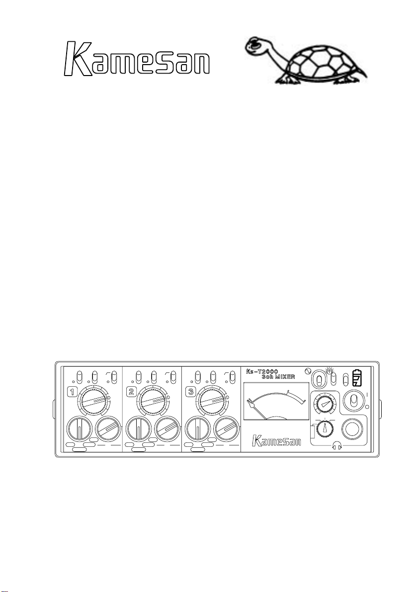
KS-T2000
Compact Audio Mixer
Operating Manual
RLRLRL
0
3
-20
0
5-
0
-4
A-B
-20
+4
84P
Lin
e
-30
Dy-M
84P
-70
Lin
0
5-
0
-4
A-B
-20
+4
e
84P
-70-30
Lin
Dy-MDy-M
0
5-
0
-4
A-B
+4
-20
e
-30
-70
VU
+
MONI
L/R
L
R
R+L


Kamesan KS-T2000
Warnings and notices
Treat your Kamesan KS-T2000 in the same way that you would
treat any piece of precision equipment. Although it is designed
for rugged location use in a wide range of extreme conditions:
• Avoid spil ling liquid over the unit or exposing it to extr emel y
humid environments.
• Do not subject the unit to extreme temperature changes, as
this may cause internal condensation, affecting the operation of the unit.
• Avoid operating the unit in extreme temperature conditions
wherever possible.
• Avoid using the unit in dusty or smoky locations wherever
possible
• When cleaning the unit, never use solvents or thinner to
clean the outside of the case. Only use a soft damp cloth to
wipe off any dirt or stains.
• Only use power supplies (batteries and external power supplies) as recommended in this manual.
Connection of microphones
notices
Warnings and
notices
Warnings and
notices
Warnings and
notices
Warnings and
notices
Warnings and
Connection of microphone cables and microphones: to prevent
hazard or damage, ensure that only microphone cables and microphones designed to the IEC 268-15A standard are connected.
Connexions des microphones et de leurs câbles: pour éviter tout
endommagement, s’assurer de brancher uniquement des microphones et des câbles de microphones conçus selon la norme IEC
268-15A.
• When using microphones, make sure that the phantom
power is set appropriately for the microphones. Use of +48 V
phantom power with microphones not designed for this may
result in damage to the microphones, and to the Kamesan
KS-T2000.
After-sales service
In the event of encountering problems with the Kamesan KST2000, you should contact your local after-sales representative.
3
notices
Warnings and
notices
Warnings and
notices
Warnings and

Kamesan KS-T2000
Table of Contents
Warnings and notices . . . . . . . . . . . . . . . . . . . . . . . . .3
Connection of microphones . . . . . . . . . . . . . . . . . . . . . . 3
After-sales service . . . . . . . . . . . . . . . . . . . . . . . . . . . . 3
Table of Contents . . . . . . . . . . . . . . . . . . . . . . . . . . . .4
General notes . . . . . . . . . . . . . . . . . . . . . . . . . . . . . .5
About this manual . . . . . . . . . . . . . . . . . . . . . . . . . . . . 5
Accessories, etc. . . . . . . . . . . . . . . . . . . . . . . . . . . . .6
About the case . . . . . . . . . . . . . . . . . . . . . . . . . . . . . . . 6
The Kamesan KS-T2000 . . . . . . . . . . . . . . . . . . . . . . .7
Input section . . . . . . . . . . . . . . . . . . . . . . . . . . . . . . . . 7
Input connections . . . . . . . . . . . . . . . . . . . . . . . . . . . . . 7
External monitoring input . . . . . . . . . . . . . . . . . . . . . . . 8
Output section . . . . . . . . . . . . . . . . . . . . . . . . . . . . . .9
Output connections . . . . . . . . . . . . . . . . . . . . . . . . . . 10
Front panel . . . . . . . . . . . . . . . . . . . . . . . . . . . . . . . . . 11
Batteries and power . . . . . . . . . . . . . . . . . . . . . . . . .12
Checking the batteries . . . . . . . . . . . . . . . . . . . . . . . . 12
Replacing the batteries . . . . . . . . . . . . . . . . . . . . . . . . 12
Extending battery life . . . . . . . . . . . . . . . . . . . . . . . . . 14
Using an external battery . . . . . . . . . . . . . . . . . . . . . . . 14
Using an AC adapter . . . . . . . . . . . . . . . . . . . . . . . . . . 14
Operations . . . . . . . . . . . . . . . . . . . . . . . . . . . . . . . .16
Channel mixing . . . . . . . . . . . . . . . . . . . . . . . . . . . . . . 16
Routing the inputs . . . . . . . . . . . . . . . . . . . . . . . . . . . 16
Low-cut filtering . . . . . . . . . . . . . . . . . . . . . . . . . . . . . 16
Monitoring . . . . . . . . . . . . . . . . . . . . . . . . . . . . . . . . . 16
Adjusting the input gain . . . . . . . . . . . . . . . . . . . . . . . 17
Setting and monitoring the output level . . . . . . . . . . . . 18
Specifications . . . . . . . . . . . . . . . . . . . . . . . . . . . . . .19
Block diagram . . . . . . . . . . . . . . . . . . . . . . . . . . . . . . 21
About “Kamesan” . . . . . . . . . . . . . . . . . . . . . . . . . . .22
4

Kamesan KS-T2000
Before\
General notes
Before operating the Kamesan KS-T2000, you should be aware
of the following points:
• All XLR connectors (male and female) are wired with the following pinouts: 1=ground, 2=hot, 3=cold.
• The AC adaptor jack is a tip-negative connection. DO NOT
attempt to make an y connection to this jack ex cep t using an
AC adaptor authorized by Kamesan.
• Always remove any dead batteries immediately from the
Kamesan KS-T2000, and remov e any batteries from the unit
if it will not be used for some time. Corroded and leaking
batteries can cause severe damage to the unit.
About this manual
Keep this manual in a convenient location for handy reference.
Any labels on the unit mentioned in the manual are shown in
this typeface: OUTPUT.
Sometimes you will see a note—important information which
you should note.
Failure to read and observe notes and warnings may result in personal injury and/or possible damage to the unit.
General notesGeneral notesGeneral notes General notesGeneral notesGeneral notesGeneral notesGeneral notesGeneral notes
5

Kamesan KS-T2000
Accessories, etc.
The Kamesan KS-T2000 is supplied with everything you need to
start work.
However, you can purchase the following, in order to increase
the capabilities and the functionality of the unit:
• Power adaptors: you can use the Kamesan PS-M12 mini
power supply.
• Spare battery holders, allowing you to slip in a new power
source at a moment’s notice.
About the case
The Kamesan KS-T2000 case is designed to hold and protect the
unit against any wear and tear under the standard conditions of
use for which the mixer is designed. In addition, the mixer itself
has been designed to be rugged and to stand up to the demands
that will be made of it in its expected life.
Even so, you should not drop the mixer, or subject it to violent
shocks or vibration. Always keep the mixer in its case to avoid
any possible damage.
If you remove the mixer from the case, and then replace it, always make sure the case clip fits over the lip at the top of the
mixer front panel.
The touch fasteners at either side may be used to tidy cables, as
well as to restrain the mixer in its case.
You can use the side pocket in the case to store spare batteries,
adaptors, etc.
You can secure the top flap using the touch fastener when it is
folded back to allow operation of the front panel.
6
Kamesan KS-T2000
The Kamesan KS-T2000
The Kamesan KS-T2000 controls and connections can be divided conveniently into three sections: the input section, the output section, and the front panel.
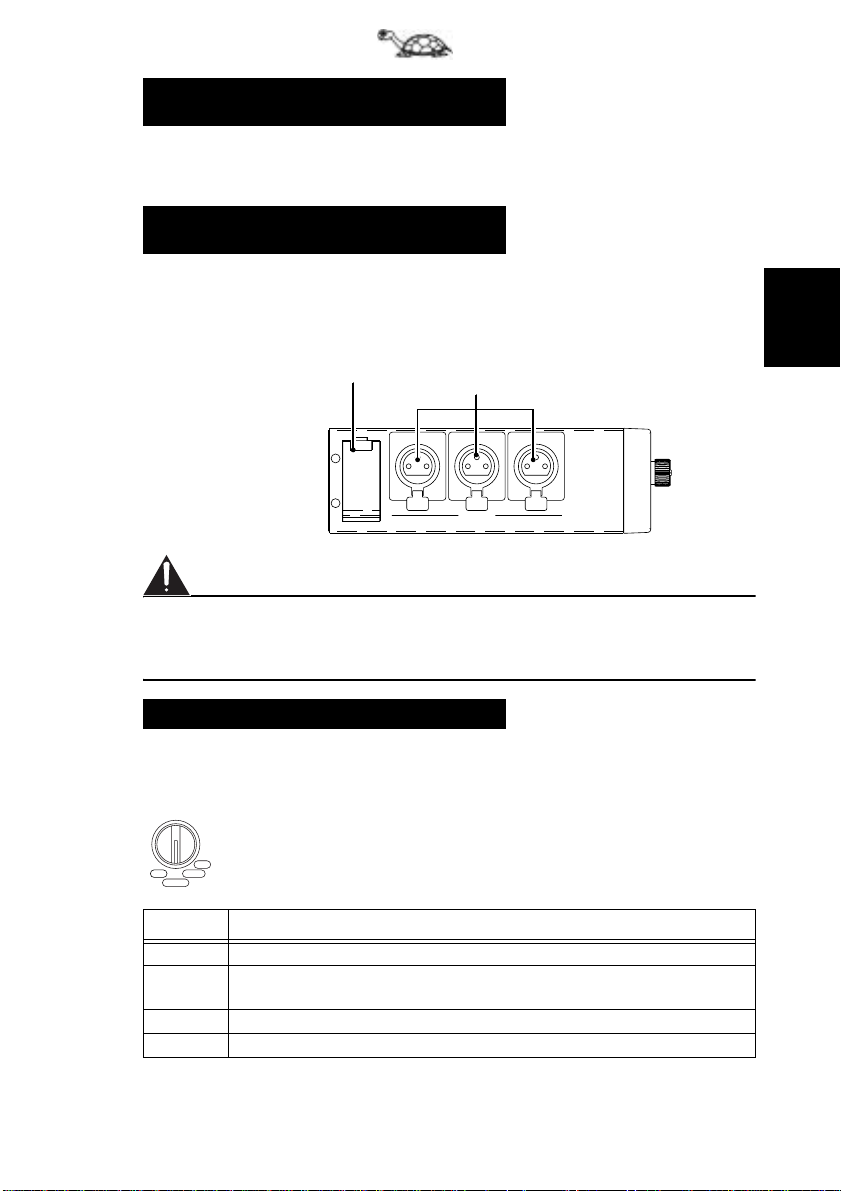
Input section
The input side of the unit (on the left as you look at the front) is
as follows):
Battery compartment
cover (catch at + side,
hinge at - side)
+
-
Always make and break connections to and from the Kamesan KST2000 with the power to the mixer and to all other equipment
turned OFF.
Input connections
The mixer can accept a number of different sources at the three
XLR input jacks. The type of input for each channel is selected
using the channel input mode selector rotary switches:
Channel input mode selector
A-B
84P
Lin
e
Dy-M
Balanced female XLR
connectors used for
microphone connection
1
INPUT
32
KS-T2000
The Kamesan
KS-T2000
The Kamesan
KS-T2000
The Kamesan
KS-T2000
The Kamesan
KS-T2000
The Kamesan
KS-T2000
The Kamesan
KS-T2000
The Kamesan
KS-T2000
The Kamesan
Setting Meaning
P48 Condenser microphones requiring a +48 V phantom power supply
Dy-M Dynamic or electret condenser microphones (no external power supply
needed) — typically –70 dBs to –30 dBs levels
LINE Line-level input (typically –20 dBm to +4 dBm levels)
A-B A-B (12V)-type microphone
7
Kamesan KS-T2000
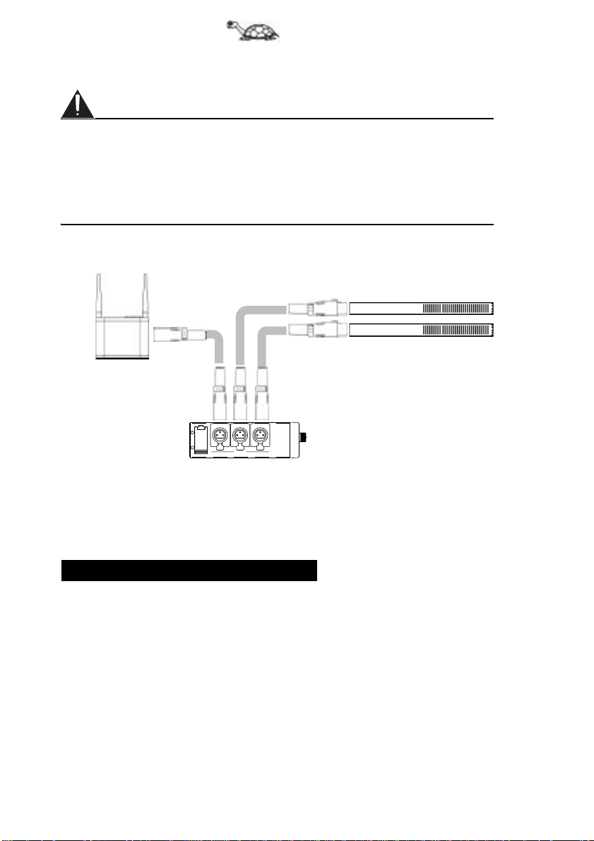
Connect balanced cables from microphones to the XLR inputs,
and set the switches appropriately:
Always make sure that the input mode selected for each channel
matches the device connected to the channel BEFORE turning on
the power. Selecting the wrong type of device could result in damage to equipment. If you have to change the input mode with the
power connector, turn down both the input level faders and the
monitoring level before changing the input mode.
For full details of the levels, impedances, etc. of these jacks, see
the section on “Specifications” on page 19.
+
-
1
32
INPUT
The illustration above shows the Kamesan KS-T2000 connected
to a pair of microphones as well as to a wireless receiver.
Note that there is one more input connection ( the external monitoring input) which may be made to the Kamesan KS-T2000, as
explained below:
External monitoring input
The Kamesan KS-T2000 allows you to input a stereo signal via a
mini 3.5 mm jack to the MONI IN input. This signal should be at
a nominal –10 dBV level.
The front panel switch controls whether this output is monitored
or not through the headphones. The level cannot be changed.
8

Kamesan KS-T2000
Output section
The output section of the unit (on the right as you look at the
front) is as follows:
Output sectionOutput sectionOutput section Output sectionOutput sectionOutput sectionOutput sectionOutput section
Master output faders (affect
both RCA and XLR outputs)
("Setting and monitoring the
Balanced XLR
mic/line-level
outputs
DC input jack
output level" on page 18
MAS.
OUT
Camera Mic
L
R
+4
MONI.
IN
Mic/line output
level switches
+10V~15V
L
-60
OUTPUT
R
+4
-60
DC IN
Unbalanced
RCA outputs
MONI IN input (for use
with camcorders,
etc.)
For full details of the levels, impedances, etc. of these jacks, see
the section on “Specifications” on page 19.
See below for details of connections.
9
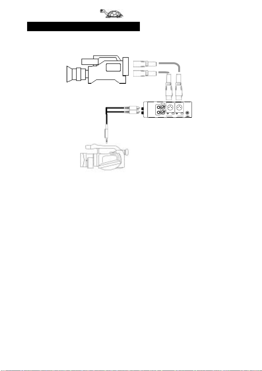
Kamesan KS-T2000
Output connections
There are two sets of connections available from the Kamesan
KS-T2000: the main balanced connectors and the unbalanced
RCA connectors.:
You can use these different connectors for professional and
semi-professional video equipmen
When you make the connections to the balanced connectors,
note that there are two switch positions for the level of these outputs: +4 and –60. Make sure that you make the appropriate level
setting for the device connected to the Kamesan KS-T2000.
10

Kamesan KS-T2000
“
Front panel
The front panel contains the individual channel controls, as well
as some master controls, etc.
Front panelFront panelFront panel Front panelFront panelFront panelFront panelFront panel
Oscillator switch (“SetInput fader (“Channel
mixing” on page 16
Output assignment switch
Routing the in-
puts” on page 16
Low--cut filter
switch “Low-cut
filtering” on
page 16
VU meter
(“Monitoring”
on page 16
ting and monitoring the
output level” on page 18
VU meter
light switch
External monitor
switch (“External
monitoring input”
on page 8)
Power switch and
battery meter (“Bat-
RLRLRL
-20
0
5-
-4
0
A-B
+4
-20
84P
Lin
e
-30
-70
Dy-M
Input mode se-
5-
0
-4
A-B
84P
Lin
e
-4
0
A-B
+4
-20
84P
Lin
e
-30
-70-30
Dy-MDy-M
lector (“Input
connections” on
VU
5-
0
0
+4
-20
-70
Monitor selector
(“Monitoring” on
page 16)
MONI
0
3
+
L/R
L
R
R+L
page 7)
teries and power” on
page 12
Headphone jack
(“Monitoring” on
page 16)
Input trim control on each
channel (“Adjusting the input gain” on page 17)
Monitor level (“Monitoring”
on page 16)
For details of the operation of these controls, see the appropriate sections of this manual.
11

Kamesan KS-T2000
Batteries and power
The Kamesan KS-T2000 can use any standard type of battery:
manganese, alkaline, nickel-cadmium, nickel-hyd ride or lith iumion. Four type 3 (AA) size batteries are required.
In normal use and temperature conditions, a set of alkaline batteries will provide between five and six hours of operation.
In addition, the Kamesan KS-T2000 can accept power from a
suitable power adaptor (described in “Using an AC adapter” on
page 14).
Checking the batteries
The three-segment LED display by
the power switch (top right of the
front panel) gives the battery status
as shown in the illustration here.
The number of LEDs lit shows the
battery status. When only the bottom orange LED is lit, it is time
to replace the batteries with a new set (30 minutes to 1 hour’s
battery life remains).
If there is no battery life at all, none of the LEDs are lit, and the
batteries should be replaced immediately.
If the unit is not to be used for an extended period of time, remove
the batteries from the unit. Do not leave dead batteries in the unit.
GOOD > 5hrs (green)
FAIR 2–5hrs (green)
REPLACE 0.5–1hr (orange)
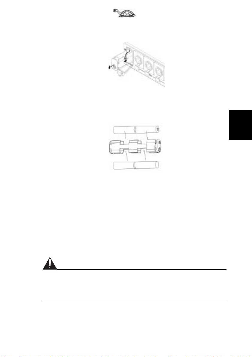
Replacing the batteries
The batteries are contained in a standard battery holder, which
slides out for easy replacement. Additional battery holders can
be purchased and “ready-loaded” with spare batteries for easy
replacement.
12
Kamesan KS-T2000
1. Remove the cover on the left (INPUT) side of the unit. You
may need to remov e the touch fastener case strap to access
the holder door.
power
Batteries and
power
Batteries and
2. Open the door using the catch located by the red (+) mark,
and remove the battery holder as shown above.
3. Remove an y old batteries in the holder and place new batteries in the holder.
• Take care that the batteries are inserted correctly as shown
above, with the polarity correct.
• Never mix batteries of different types, or discarded (or partially-discharged) and new (or freshly-charged) batteries.
• Always follow the battery manufacturer’s instructions for
charging rechargeable batteries. Never attempt to recharge
batteries which are not designed for this purpose.
4. Replace the battery holder into the Kamesan KS-T2000 and
close the battery doo r. Replace the case strap in its original
position.
power
Batteries and
power
Batteries and
power
Batteries and
power
Batteries and
power
Batteries and
power
Batteries and
The battery holder should be inserted with the end with two battery
contacts entering the compartment first, and with the single metal
rivet towards the hinge of the holder door (as shown in the illustration above.
5. Test the battery power and polarity with the power switch
(see “Checking the batteries” on page 12).
13

Kamesan KS-T2000
Note that when new batteries are inserted, the indicators may show
the middle or low battery condition. This is because the power LEDs
monitor the actual real-time battery usage, and when the unit is actually in use (phantom power, headphone amp, etc.), the true battery status will be shown.
Extending battery life
• Do not use the VU meter light more than necessary (this can
result in considerable savings).
• Turn off the power to the Kamesan KS-T2000 when it is not
in use (“resting” the batteries can increase the battery life
very significantly).
• Setting the XLR output level switch to the +4 setting can
reduce battery consumption.
• Cold batteries have a shorter life than warm ones. In winter
or other cold conditions, you may want to k eep the batteries
warm when they are not in use. At 0°C (32°F), battery life is
about 60% less than at 20°C (68°F).
Using an external battery
• As long as the connector conforms to the polarity of the
Kamesan KS-T2000 connector (tip negative), a BP-90-type
battery can be used for external power of the mixer.
Using an AC adapter
The Kamesan KS-T2000 can use one of two optional external
adapters:
• PS-M12 mini power supply
• SS-40611 MkII low noise power supply
Alternatively, any other power supply may be used (although this
is not recommended), provided that it conforms to the following
specifications:
Connector: BP-90 type with tip negative
Voltage: >9.0 V and <16.0 V
Power: >0.5 A
• Any non-Kamesan AC adapter should also incorporate ripple
reduction circuitry.
14

Kamesan KS-T2000
The use of any adapter other than the type specified here may result in damage to the Kamesan KS-T2000, other equipment, or
even result in overheating and fire. For this reason, it is essential
that only those adapters recommended and sold by Kamesan are
used.
Connect the adapter connector to the DC IN connector of the Kamesan KS-T2000, making sure that the polarity of the adapter
connector matches that of the Kamesan KS-T2000.
• When DC power is supplied to the Kamesan KS-T2000, this
takes priority over any internal batteries (which are not used
when the adapter is connected and power is supplied). When
the adapter is disconnected, the batteries are used again.
power
Batteries and
power
Batteries and
power
Batteries and
power
Batteries and
power
Batteries and
power
Batteries and
15
power
Batteries and
power
Batteries and

Kamesan KS-T2000
Operations
The following explains some of the principles of operating the
Kamesan KS-T2000 when all the connections have been made:
Channel mixing
Adjust the relative levels of the inputs by using the level controls
(faders).
Turning these controls fully counterclockwise attenuates the signals, and turning them fully clockwise boosts them.
The nominal position (neither cut nor boost) is marked as shown
here.
Nominal position
To make the best use of the Kamesan KS-T2000’s gain structure,
we recommend setting the channel fader control to this nominal
position, and adjusting the trim level to obtain the appropriate
reading on the VU meter (as described in “Adjusting the input
gain” on page 17).
Routing the inputs
Each input can be assigned to either the left master output, the
right master output, or both.
Use the L and R switches to send the input signals to
RL
the left and right outputs:
When these switches are in the up position, the input
is assigned to the appropriate output bus.
Low-cut filtering
The Kamesan KS-T2000 provides three low-cut (highpass) filters at 160 Hz with a slope of –12 dB/octave.
Use these independently-switchable filters (one on each
channel) to counteract the effects of wind noise, rumble, etc.
Set the switch to the up position to engage the filter.
Monitoring
Use the headphone jack to monitor the outputs.
The volume output from the headphones is adjusted with the
(yellow) control.
16

Kamesan KS-T2000
The signal or signals being monitored and metered are set using
the (green) monitor selection control.
L/R
L
R
R+L
Monitoring switch settings
OperationsOperationsOperations OperationsOperationsOperationsOperationsOperations
Switch
setting
[L+R]
L
L/R
R
The [L+R] setting is also used for the external monitoring source
(see “External monitoring input” on page 8).
Meter displays
L & R sum L & R sum summed busses for
left left monitor left bus only
left left right Normal stereo operation
right right Monitor right bus only
Channel Comment
LR
checking
Adjusting the input gain
Before adjusting the inputs:
1. Make sure that the correct input mode has been selected
(“Input connections” on page 7).
2. If the low-cut filter is to be used on the input channel, make
sure that it is enabled (“Low-cut filtering” on page 16).
3. Ensure that the input is routed appropriately (“Routing the
inputs” on page 16).
4. Ensure that an appropriate monitoring mode is selected
(“Monitoring” on page 16).
5. Turn down all input faders,
adjusted, which should be set to the nominal position.
6. While the input sound is being input through the microphone, etc., turn the channel’s input gain control so that the
VU meter indicates a healthy level (not into the red, but
“kicking” the 0 mark is fine).
7. When the level has been se t up to your satisfaction, turn the
channel’s input fader all the way down, and repeat the process for all the other channels in turn.
except
the one which is to be
17

Kamesan KS-T2000
The gain level for all types of microphone ranges from –30 to –
70 dBs (marked in white; the –40 and –50 points are marked for
convenience), and the gain level for line-level sources ranges from
–20 to +4 dBm (marked in blue).
The head and mixer amps of the Kamesan KS-T2000 allow considerable leeway. On the input stage, there is about 28 dB available, and on the output stage, about 17 dB is available
Setting and monitoring the output level
To help you match the levels of the Kamesan KS-T2000 with the
recorder connected to the outputs, the mixer is fitted with an integral 1 kHz line-up oscillator.
In order to see the output level using the oscillator:
1. Make sure that both the OUTPUT level switches are set to the
correct value (usually +4).
2. Turn the power on (up), and then turn the oscillator switch
on (up).
3. To monitor both channels together, set the monitoring selection switch to the L/R setting (see “Monitoring” on page 16
for an explanation of the monitoring switch settings).
4. Adjust the level of the outputs so that the VU meter reads
0dB.
5. Remember to turn the oscillator off when the adjustment
has been made.
18

Kamesan KS-T2000
Specifications
Inputs
Input levels
MIC
LINE
External monitor input
Input impedance
MIC
LINE
External monitor input
Input headroom
–70 to –30 dB s (balance d inputs)
–20 to +4 dB m (balanced inputs)
0dBs
3.0 kΩ(dynamic microphone)
600 Ω
600 Ω
> 30 dB (pre-fader input)
Outputs
Output levels
MAIN L/R +4/–60 dBm switchable (transformer balanced) Cannon 3-pin
Unbalanced
outputs
Monitor outputs +10 dBs/50 Ω (maximum 8 W stereo)
Maximum output
MAIN L/R +23 dBm (600 Ω @ +4 setting)
Unbalanced
outputs
Monitor outputs –10 dBs (50 Ω), stereo jack
a. The above measurements are all made with the battery voltage at 6.0 V
–60 dBm (compatible with impedance 600 Ω to 10 kΩ (RCA pin
jacks)
a
–40 dBs (10 kΩ)
SpecificationsSpecificationsSpecifications SpecificationsSpecificationsSpecificationsSpecificationsSpecifications
Audio performance figures
Frequency
response
Noise level
50 Hz to 15 kHz (±0.5 dB)
MIC (–70) <–55 dB (with 30 kHz LPF/RMS)
LINE (+4) <–69 dB (with 30 kHz LPF/RMS)
MONI –65 dB (30 kHz LPF/RMS)
Total Harmonic
Distortion (THD)
<0.1% (50 Hz to 15 kHz at nominal levels)
19

Kamesan KS-T2000
Other parameters
Microphone power
P-48 (+48 V
phantom
powering)
A-B (12 V) Maximum power: 30 mA
LCF (low-cut
filter)
Oscillator 1 kHz (±5%)
Internal power
supply
Battery life Better than 6 hours with alkaline batteries at normal temperature
External power
Voltage +9.0 V to 16.0 V
Current Nominal 0.15 A, Maximum 0.5 A
Dimensions (w x d
x h excluding
controls)
Weight (main unit
only, excluding
case and batteries
Maximum power: 10 mA
160 Hz (–12 dB/octave slope)
Electrical characteristics
4 x type 3 (AA) dry-cell batteries, mounted in supplied standard
battery holder
conditions
Physical characteristics
201 x 140 x 47 (mm)
8 x 4 x 2 (in)
1kg (2.2lb.)
20
Kamesan KS-T2000
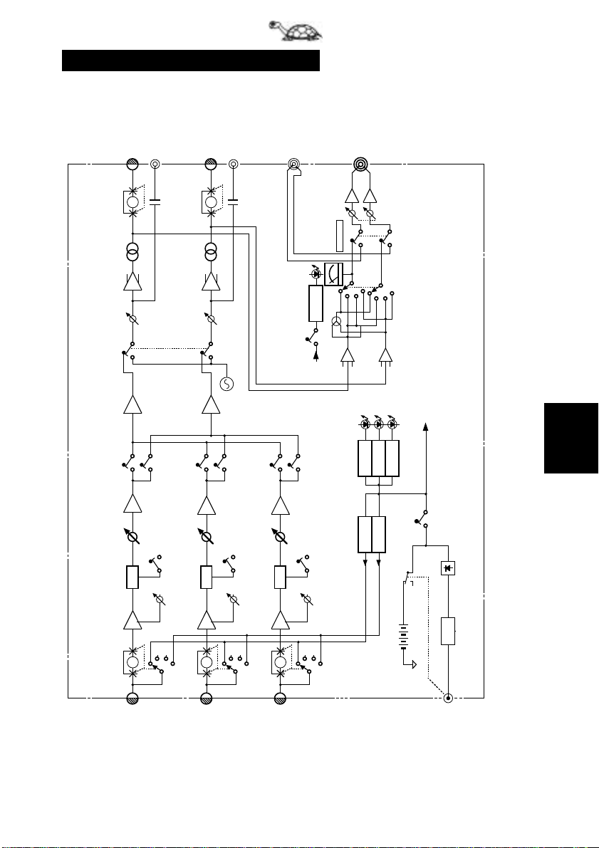
Block diagram
(+4/-60dBm)
OUTPUT L
(3-31)
P
BTL
OSC
MIX
L
BA
Balance)
・
(-60dBs:UN
(max+23dBm)
(RCA)
+4/-60
T
OUT L MAS
R
OUTPUT R
(+4/-60dBm)
(max+23dBm)
P
BTL
MIX
L
R
BA
(-60dBs:Unbalanced)
+4/-60
T
OUT R MAS
OSC
(Φ3.5mm mini-jack)
L
BA
(0dBs / 600Ω:Unbalanced)
EXT MONI IN
+6V->+12V
Lamp
+6V
R
Convert
(Φ6.5mm Phone jack)
BA
EXT MONI
OUT
VU
L+R
L/R
L
MIX
BAL
IN
MONI OUT
(-10dBs / max+5dBs)
BA
VR
EXT
R
IN
Gr.
>6H2H
3H0.5H
FAIR
GOOD
POWER IND.
BAL
Gr.
Or.
1H0.5H
REPLANCE
Batt. Minimum voltage=+4.4V
Low Batt.=put out light
SpecificationsSpecificationsSpecifications SpecificationsSpecificationsSpecificationsSpecificationsSpecifications
+6V+9V
(3-32)
VR
HPF
HPF
INPUT GAIN
HA
D MIC
P-48 MIC
P
+4/-30
)
)
Ω
Ω
+4dBm / 600
-30dBm / 3K
〜
〜
INPUT 1ch
(-30
(-70
160Hz
MIC(-70~-30dB)
LINE
A-B MIC
LINE(-20~+4dB)
VR
HPF
HPF
INPUT GAIN
HA
P-48 MIC
P
+4/-30
INPUT 2ch
D MIC
160Hz
LINE
-30dB)
〜
MIC(-70
A-B MIC
+4dB)
〜
LINE(-20
VR
HPF
HPF
INPUT GAIN
HA
P-48 MIC
P
+4/-30
INPUT 3ch
160Hz
D MIC
21
MIC(-70~-30dB)
LINE(-20~+4dB)
LINE
A-B MIC
DC Convert
+6V->+48V
+6V->12V
POWER SW
DC Convert
4)
×
DRY BATTERY
BATTERIES(AA/SUM-3
ON
9V Reg
C.G.
(DC Power jack)
+16V)
〜
DC IN (+9

Kamesan KS-T2000
About “Kamesan”
Sigma Systems Engineering was started in 1972 to develop and
design professional mixers for studio and remote broadcast applications. Today, following the “slow and steady” principle of
the tortoise, we have built up our sales and our reputation to the
extent that we now enjoy 95% of the Japanese portable mixer
market.
We have concentrated on two or three mai n areas in our desi gn
philosophy: compactness, in an industry which was traditionally
dominated by large, heavy equipment; ease of use, since time is
always of the essence in the environments where our products
are used; and quality, to match the needs that today’s broadcasters require.
Our head office is in Shinjuku, Tokyo, and as a small company,
we are happy to listen to the ideas for product improvement suggested by you, the customers and users of our equipment.
Making steady progress (like a tortoise, (but maybe a little faster!), we hope to meet your requirements, now and in the future.
Visit our Web sites at http://www.kamesan.co.jp and
http://www.kamesan.info in order to find out more about what
we’re doing, and to let us know what you are doing with Kamesan products.
22


Sigma Systems Engineering Co. Ltd.
3-5-2 Okubo
Shinjuku-ku
Tokyo 169-0072
JAPAN
Tel: +81 3 3204 2611
Fax: +81 3 3204 2250
e-mail: sales@kamesan.co.jp
 Loading...