

Page 1
D01047820C
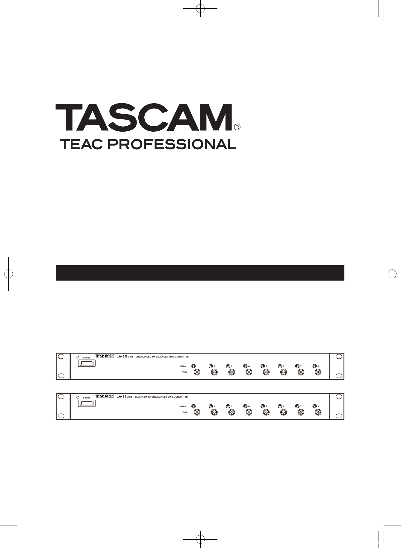
LA-80@#/81 @#
Unbalanced/Balanced Line Converter
OWNER'S MANUAL
E_LA-80-81mkII_RevC.indd 1 08.12.19 1:07:22 PM
Page 2

2 TASCAM LA-80/81MKII
The exclamation point within an equilateral triangle is intended to alert the user to
the presence of important operating and maintenance (servicing) instructions in
the literature accompanying the appliance.
The lightning flash with arrowhead symbol, within equilateral triangle, is intended
to alert the user to the presence of uninsulated “dangerous voltage” within the
product’s enclosure that may be of sufficient magnitude to constitute a risk of
electric shock to persons.
CAUTION: TO REDUCE THE RISK OF ELECTRIC SHOCK, DO NOT REMOVE
COVER (OR BACK). NO USER-SERVICEABLE PARTS INSIDE. REFER SERVICING
TO QUALIFIED SERVICE PERSONNEL.
WARNING: TO PREVENT FIRE OR
SHOCK HAZARD, DO NOT EXPOSE THIS
APPLIANCE TO RAIN OR MOISTURE.
Thi s a p p lia n c e ha s a s e r ial n u m b er
located on the rear panel. Please record
th e m od el numbe r a nd ser ia l n umber
and retain them for your records.
Model number
Serial number
For the customers in Europe
WARNING
This is a Class A product. In a domestic environment,
this product may cause radio interference in which
ca se the user may be req uired to take ade quate
measures.
Pour les utilisateurs en Europe
AVERTISSEMENT
Il s'a gi t d' u n pro d u it d e Cl as s e A. Da n s un
env i r o nnement do m e s t i que, cet ap p a r e il pe u t
pr ovoqu er d es i nterfé ren ces rad io, da ns c e ca s
l'utilisateur peut être amené à prendre des mesures
appropriées.
Für Kunden in Europa
Warnu ng
Dies ist eine Einrichtung, welche die Funk-Entstörung
nach Klasse A besitzt. Diese Einrichtung kann im
Wo h n bereic h Funkst ö r ungen ve r s u r sachen; in
dies em Fa ll kann vom Betriebe r ver lang werde n,
angemessene Maßnahmen durchzuführen und dafür
aufzukommen.
TO THE USER
This e q u ipment ha s b e e n te sted an d f o und to
comply with the limits for a Class A digital device,
pursuant to Part 15 of the FCC Rules. These limits
are d esig ned to prov i de re asona ble pr ote c tion
against harmful interference when the equipment
is o p erat ed in a c omme r cial e nvi ronm e nt. T h is
equipment generates, uses, and can radiate radio
frequency energy and, if not installed and used in
accordance with the instruction manual, may cause
harmful interference to radio communications.
Operation of this equipment in a residential area is
likely to cause harmful interference in which case the
user will be required to correct the interference at his
own expense.
CAUTION
Changes or m odifi catio ns to thi s equipment not
expressly approved by TEAC CORPORATION for
compliance could void the user's authority to operate
this equipment.
For U.S.A.
CE Marking Information
a) Applicable electromagnetic environment: E4
b) Peak inrush current: 4.2 A
In North America use only on 120V supply.
IMPORTANT SAFETY PRECAUTIONS
E_LA-80-81mkII_RevC.indd 2 08.12.19 1:07:23 PM
Page 3
TASCAM LA-80/81MKII 3
1 Read these instructions.
2 Keep these instructions.
3 Heed all warnings.
4 Follow all instructions.
5 Do not use this apparatus near water.
6 Clean only with dry cloth.
7 Do not block any ventilation openings. Ins tall in
accordance with the manufacturer's instructions.
8 Do not install near any heat sou rc es such as
radiators, heat registers, stoves, or other apparatus
(including amplifiers) that produce heat.
9 Do not defeat the safety purpose of the polarized
or grounding-t ype plug. A polarized plug has t wo
blades with one wider than the other. A grounding
ty pe plug has two blades and a third grounding
prong. The wide blade o r the third prong are
provided for your safety. If the provided plug does
not fit into your outlet, consult an electrician for
replacement of the obsolete outlet.
10 Prote ct the p ower cord from b eing walked on
or pinched particularly at plugs, convenience
receptacles, and the point where they exit from the
apparatus.
11 Only use attachments/accessories specified by the
manufacturer.
12 Use only with the cart, sta nd, tripod, bracket, o r
table specified by the manufacturer, or sold with the
apparatus. When a cart is used, use caution when
moving the cart/apparatus c ombinatio n to avoid
injury from tip-over.
13 Unplug this apparatus during lightnin g s torm s or
when unused for long periods of time.
14 Refer all se rvicing to qualifie d ser vice personnel.
Servicing is required when the apparatus has been
damaged in any way, such as power-supply cord or
plug is damaged, liquid has been spilled or objects
have fallen into the apparatus, the apparatus has
been exposed to rain or moisture, does not operate
normally, or has been dropped.
Do not expose this apparatus to drips or splashes.
•
Do not place any objects filled with liquids, such as
•
vases, on the apparatus.
Do not install this apparatus in a confined space such
•
as a book case or similar unit.
The apparatus draws nominal non-operating power
•
from the AC outlet with its POWER or STANDBY/ON
switch not in the ON position.
The apparatus should be located close enough to the
•
AC outlet so that you can easily grasp the power cord
plug at any time.
The main plug is used as the disconnect device, the
•
disconnect device shall remain readily operable.
An apparatus with Class I c onstruction shall be
•
connected to an AC outlet with a protective grounding
connection.
Batteries (battery pack or batteries installed) shall not
•
be exposed to excessive heat such as sunshine, fire or
the like.
Excessive sound pressure from earphones and head-
•
phones can cause hearing loss.
IMPORTANT SAFETY INSTRUCTIONS
E_LA-80-81mkII_RevC.indd 3 08.12.19 1:07:23 PM
Page 4
4 TASCAM LA-80/81MKII
Contents
1–Introduction ...................................................... 5
Overview .............................................................. 5
Supplied accessories ............................................5
Precautions for placement and use ..................... 5
Cleaning the unit .................................................. 5
Rack-mounting the unit .......................................5
2–Names and Functions of Parts ...................6
Front panel (LA-80MKII) ...................................... 6
Rear panel (LA-80MKII) ........................................ 6
Front panel (LA-81MKII) ....................................... 7
Rear panel (LA-81MKII) ........................................ 7
Bottom panel (LA-80MKII) ................................... 8
Bottom panel (LA-81MKII) ................................... 8
Block diagram (LA-80MKII) ................................. 9
Level diagram (LA-80MKII) .................................. 9
Block diagram (LA-81MKII) ............................... 10
Level diagram (LA-81MKII) ................................. 10
3–ADA Functions ................................................ 11
LA-80MKII ADA Functions .................................. 11
Example 1 (LA-80MKII) .............................................. 11
Example 2 (LA-80MKII) .............................................. 11
LA-81MKII ADA Functions .................................. 12
Example 1 (LA-81MKII) .............................................. 12
Example 2 (LA-81MKII) .............................................. 12
4–Specifications .................................................. 13
Inputs and Outputs ............................................ 13
Performance ....................................................... 13
Other specifications ........................................... 14
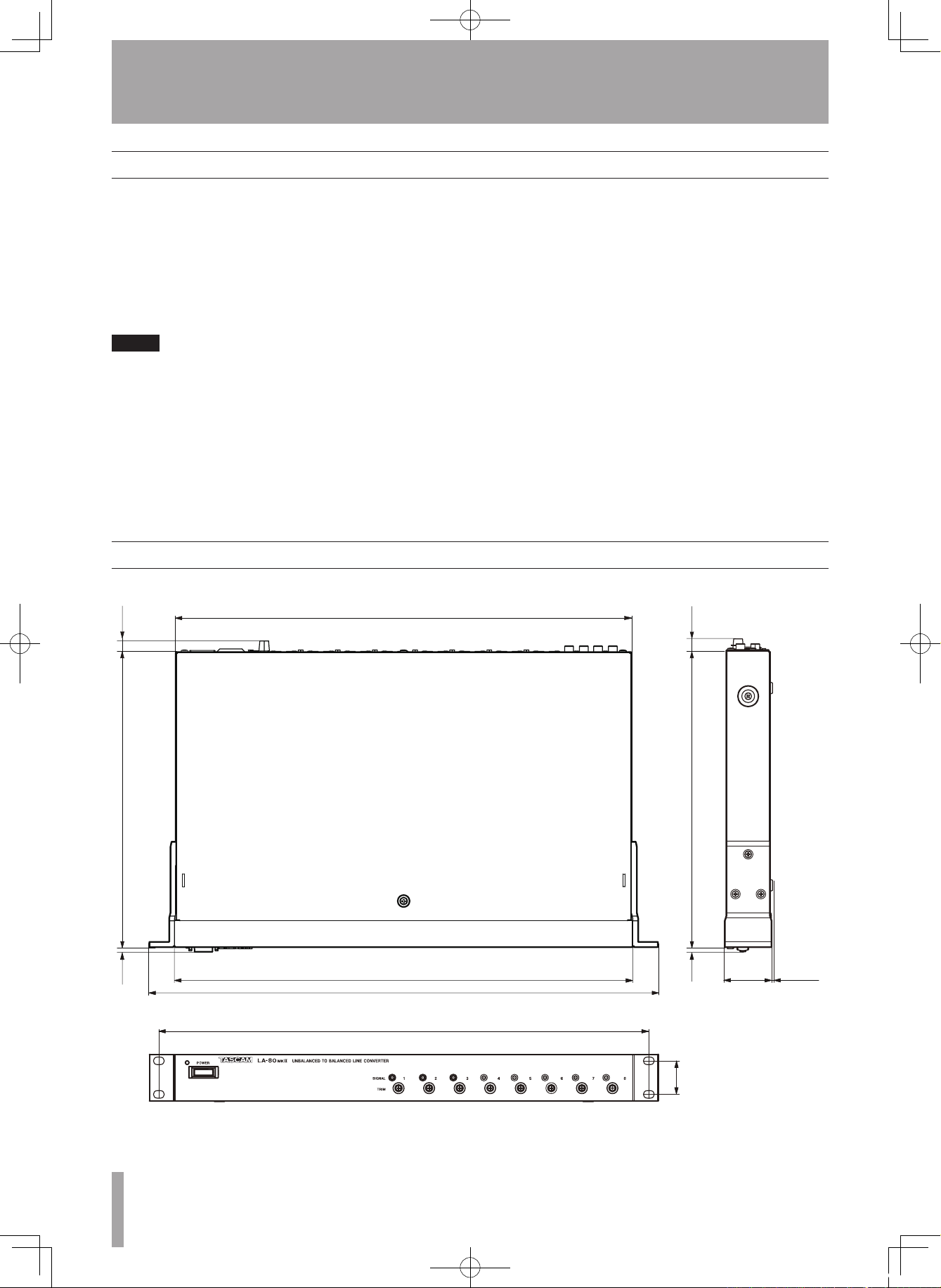
Dimensional drawings ........................................ 14
E_LA-80-81mkII_RevC.indd 4 08.12.19 1:07:23 PM
Page 5
TASCAM LA-80/81MKII 5
1–Introduction
Thank you very much for purchasing a TASCAM
LA-80/81MKII. Please read this Owner’s Manual
carefully and understand how to operate the device
correctly before use. We hope that you will fully use
the features of this unit for many years to come. After
reading this manual, please keep it in a convenient
place for future reference.
The LA-80MKII has 8 internal circuits to convert
unbalanced inputs to balanced outputs. In addition, the
Audio Distributed Amplier (ADA) function allows
single inputs to be assigned to multiple outputs using
the INPUT LINK switches between each channel.
The LA-81MKII has 8 internal circuits to convert
balanced inputs to unbalanced outputs.
Moreover, LA-80/81MKII units also have the
following functions.
GND LIFT• switches to turn the ground ON and OFF
for each balanced connector
ALL LIFT• switch that turns the ground ON and OFF
for the entire unit
Each channel has an • INPUT/OUTPUT LEVEL switch
that allows input and output levels to be switched
between -20 dBu and +4 dBu
Level indicator LEDs that show signal presence •
Semi-fixed • TRIM controls for fine level adjustment
of ±12 dB
Rack mount brackets•
Three-prong AC power outlet (Not on EUR model)•
Overview
Supplied accessories
The following items are included with this product.
Main unit • ...................................................................1
Power cord set• .............................................................1
Rack mount screw set• .................................................1
Owner’s Manual (this document)• ...............................1
Warranty card• .............................................................1
Contact your TASCAM supplier if any of these items
are missing.
Precautions for placement and use
Cleaning the unit
Use this unit within its operating temperature range •
of 5–40º C (40–104º F). In addition, please avoid
placement in locations that are very dusty or humid
because this could cause malfunction.
Do not give the unit a violent shock. This could •
cause damage to the internal circuitry or the case.
NOTE
Please be aware that, as a result of improvements or other
changes to the product, photographs, illustrations and
other depictions in the Owner’s Manual may differ from
the actual product.
Use a soft cloth to wipe the unit clean. Do not
clean it with chemical-based wipes, benzene,
thinner, alcohol or similar substances. This could
damage the surface or cause the color to change.
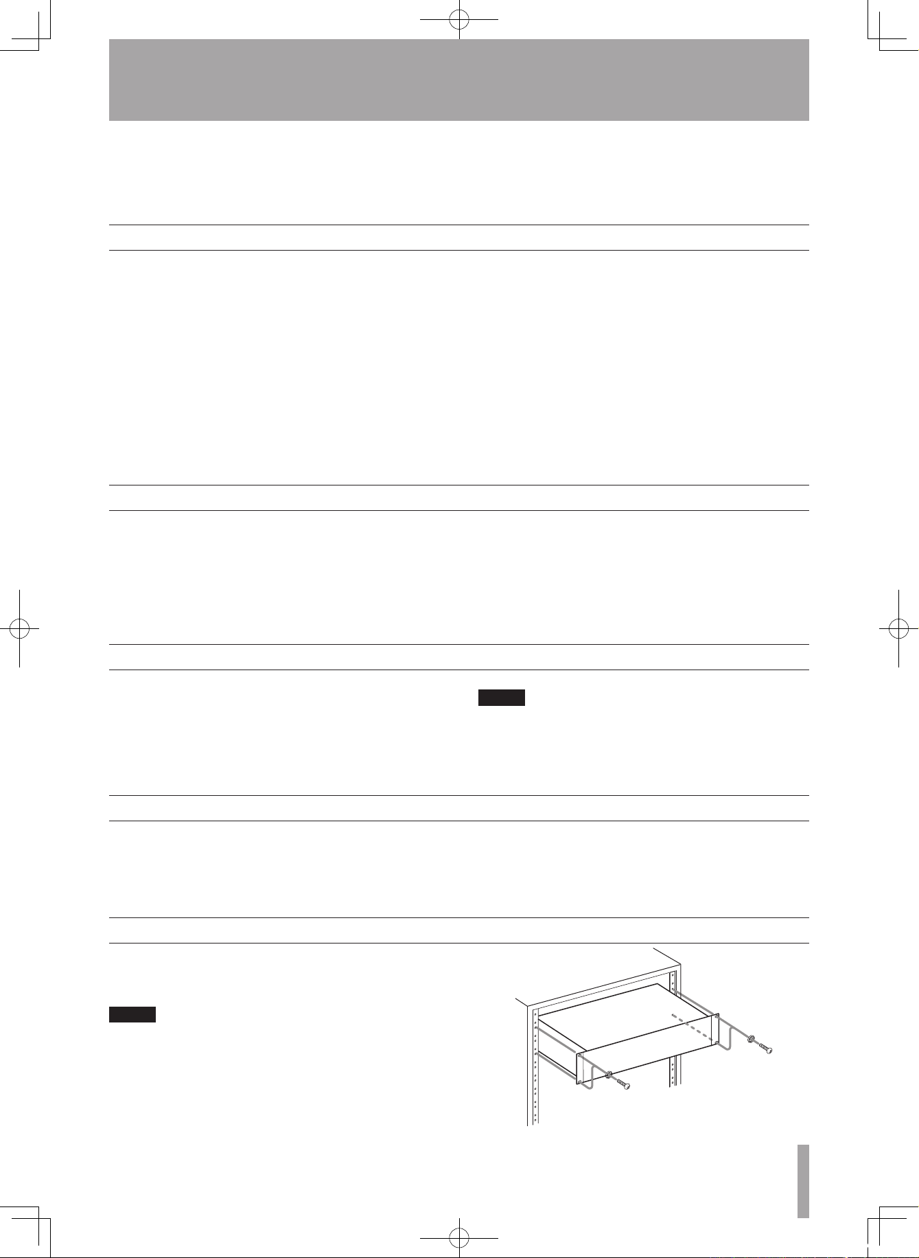
Rack-mounting the unit
Use the supplied rack-mounting kit to mount the unit
in a standard 19-inch rack, as shown below. Remove
the feet of the unit before mounting.
NOTE
Leave 1U of space above the unit for ventilation.•
Allow at least 10 cm (4 in) at the rear of the unit for •
ventilation.
E_LA-80-81mkII_RevC.indd 5 08.12.19 1:07:23 PM
Page 6
6 TASCAM LA-80/81MKII
2–Names and Functions of Parts
Front panel (LA-80MKII)
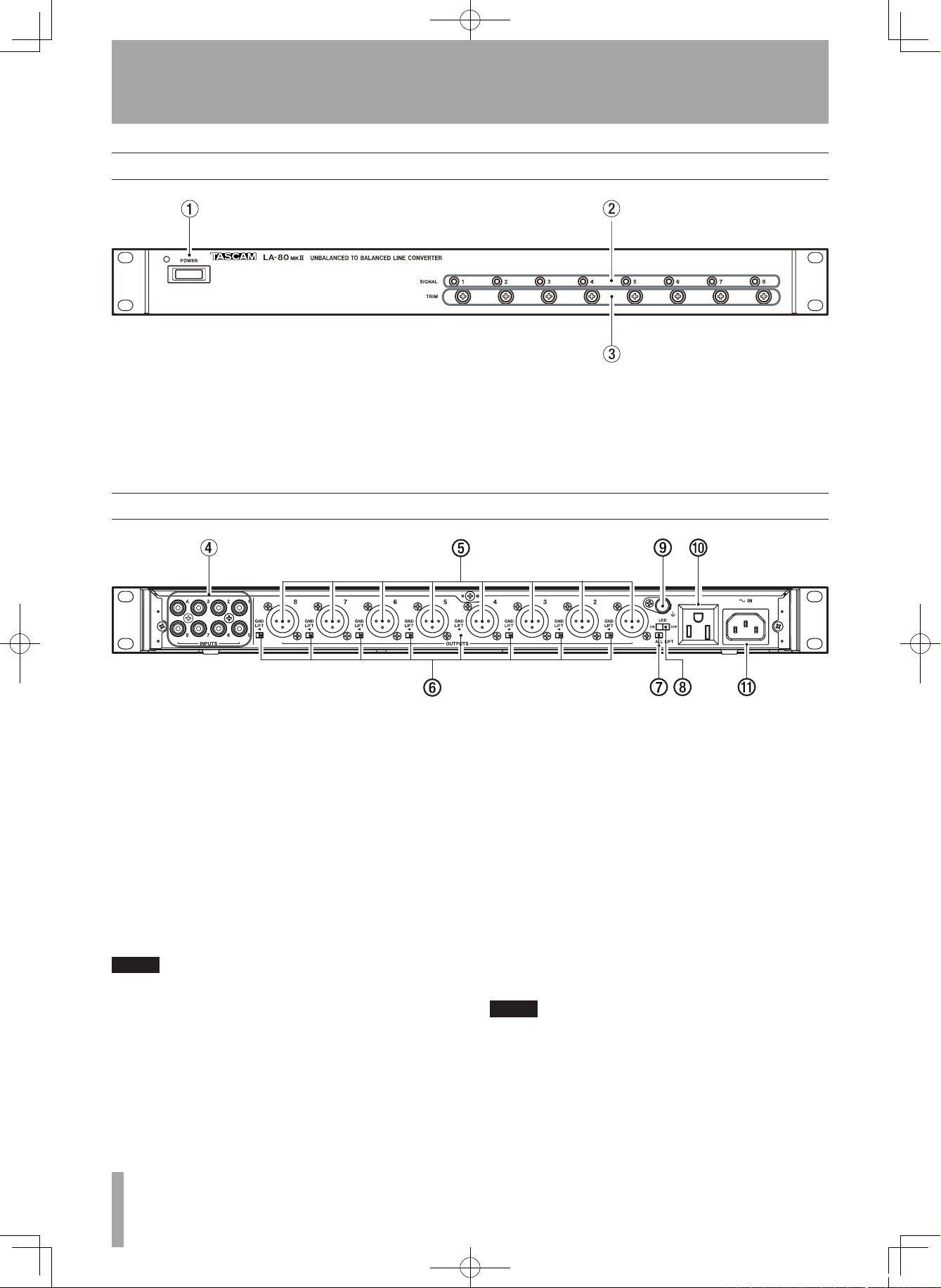
1 POWER switch and LED
Turns power ON and OFF.
2 LED indicators
Indicate the presence of input signals.
3 TRIM (UNBALANCED TO BALANCED) 1–8
These semi-fixed trim controls allow output signal
levels to be adjusted in a range of ±12 dB.
Rear panel (LA-80MKII)
4 INPUTS 1–8
RCA pin jack type input connectors with nominal
input levels of -10 dBV (0.3 V).
5 OUTPUTS 1–8
XLR type output connectors with nominal output
levels of +4 dBu (1.23 V) or -20 dBu (0.0775 V).
6 GND LIFT switches
In a studio or other place where multiple units are
connected, a ground loop can occur through the
wiring, and this loop can cause a hum or other
noise. If this occurs, engage GND LIFT switches to
cut ground loops from the (balanced) OUTPUTS 5.
NOTE
The GND LIFT switches do not cut the ground for the
INPUTS 4.
7 ALL LIFT switch
When other equipment is mounted in the same
metal rack, for example, a ground loop can occur
through the panel or chassis, and this loop can
cause a hum or other noise. If this occurs, engage
the ALL LIFT switch to cut the loop.
8 Level indicator LED switch
If this switch is ON, LEDs light when input signals
are present. If this switch is OFF, the LEDs do not
light regardless of the presence of input signals.
9 GND connector
When multiple pieces of equipment are connected,
use this to make the chassis of each piece of
equipment have the same electrical potential.
0 Power outlet (see NOTE below)
Use this three-prong outlet, which is not affected
by the power switch, to connect AC equipment
with a maximum power consumption of 400 W
(or 3A). This connector is convenient when using
multiple LA-80/81MKII units. The specifications
are displayed on the top of the unit.
NOTE
The EUR model does not have this power outlet, so the
panel here is blank.
q AC IN connector
Connect the included power cord.
E_LA-80-81mkII_RevC.indd 6 08.12.19 1:07:24 PM
Page 7
TASCAM LA-80/81MKII 7
Front panel (LA-81MKII)
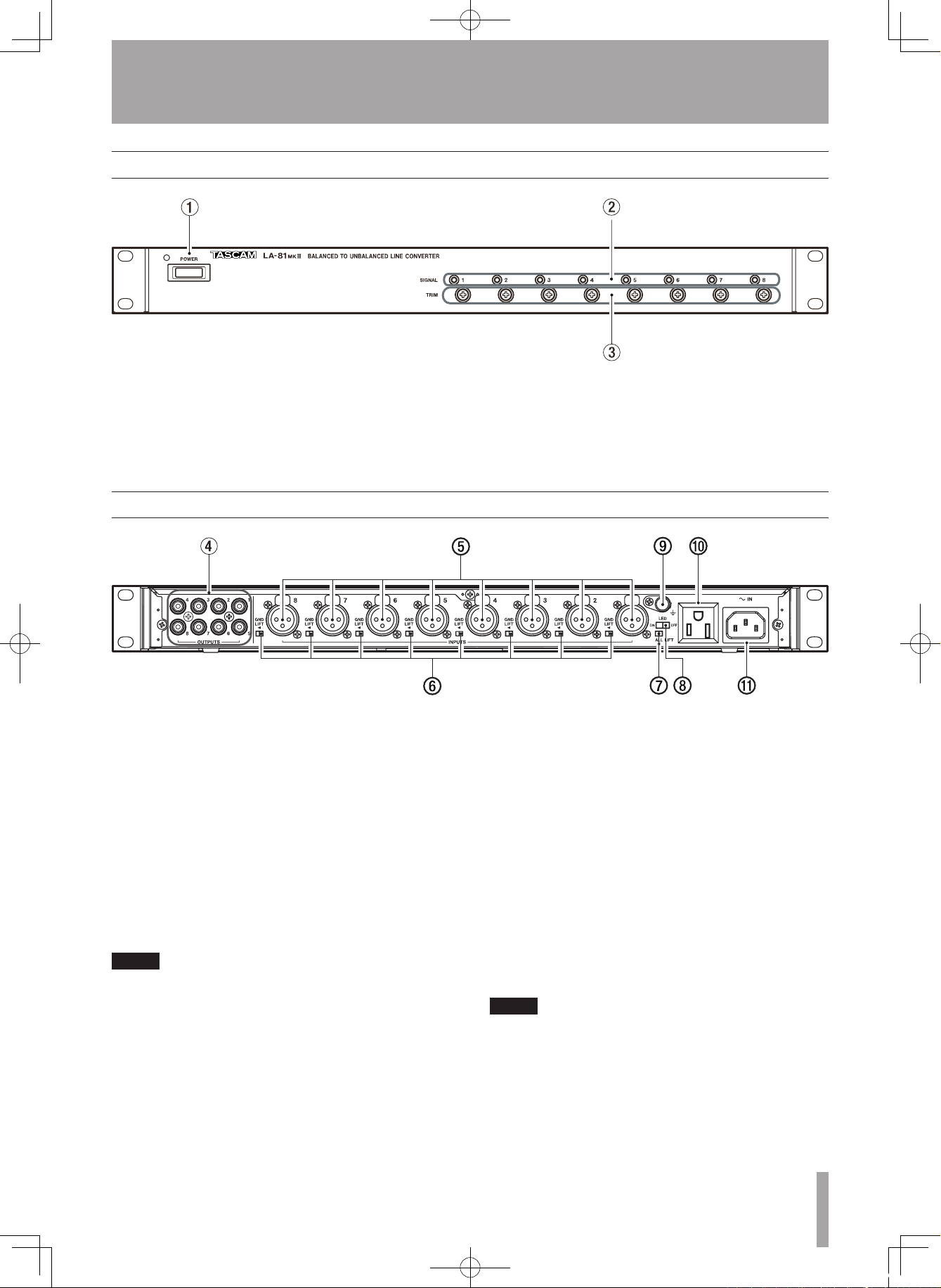
1 POWER switch and LED
Turns power ON and OFF.
2 LED indicators
Indicate the presence of input signals.
3 TRIM (BALANCED TO UNBALANCED) 1–8
These semi-fixed trim controls allow output signal
levels to be adjusted in a range of ±12 dB.
2–Names and Functions of Parts
Rear panel (LA-81MKII)
4 OUTPUTS 1–8
RCA pin jack type output connectors with nominal
output levels of -10 dBV (0.3 V).
5 INPUTS 1–8
XLR type input connectors with nominal input
levels of +4 dBu (1.23 V) or -20 dBu (0.0775 V).
6 GND LIFT switches
In a studio or other place where multiple units are
connected, a ground loop can occur through the
wiring, and this loop can cause a hum or other
noise. If this occurs, engage GND LIFT switches to
cut ground loops from the (balanced) INPUTS 5.
NOTE
The GND LIFT switches do not cut the ground for the
OUTPUTS 4.
7 ALL LIFT switch
When other equipment is mounted in the same
metal rack, for example, a ground loop can occur
through the panel or chassis, and this loop can
cause a hum or other noise. If this occurs, engage
the ALL LIFT switch to cut the loop.
8 Level indicator LED switch
If this switch is ON, LEDs light when input signals
are present. If this switch is OFF, the LEDs do not
light regardless of the presence of input signals.
9 GND connector
When multiple pieces of equipment are connected,
use this to make the chassis of each piece of
equipment have the same electrical potential
0 Power outlet (see NOTE below)
Use this three-prong outlet, which is not affected
by the power switch, to connect AC equipment
with a maximum power consumption of 400 W
(or 3A). This connector is convenient when using
multiple LA-80/81MKII units. The specifications
are displayed on the top of the unit.
NOTE
The EUR model does not have this power outlet, so the
panel here is blank.
q AC IN connector
Connect the included power cord.
E_LA-80-81mkII_RevC.indd 7 08.12.19 1:07:25 PM
Page 8
8 TASCAM LA-80/81MKII
2–Names and Functions of Parts
Bottom panel (LA-80MKII)
Bottom panel (LA-81MKII)
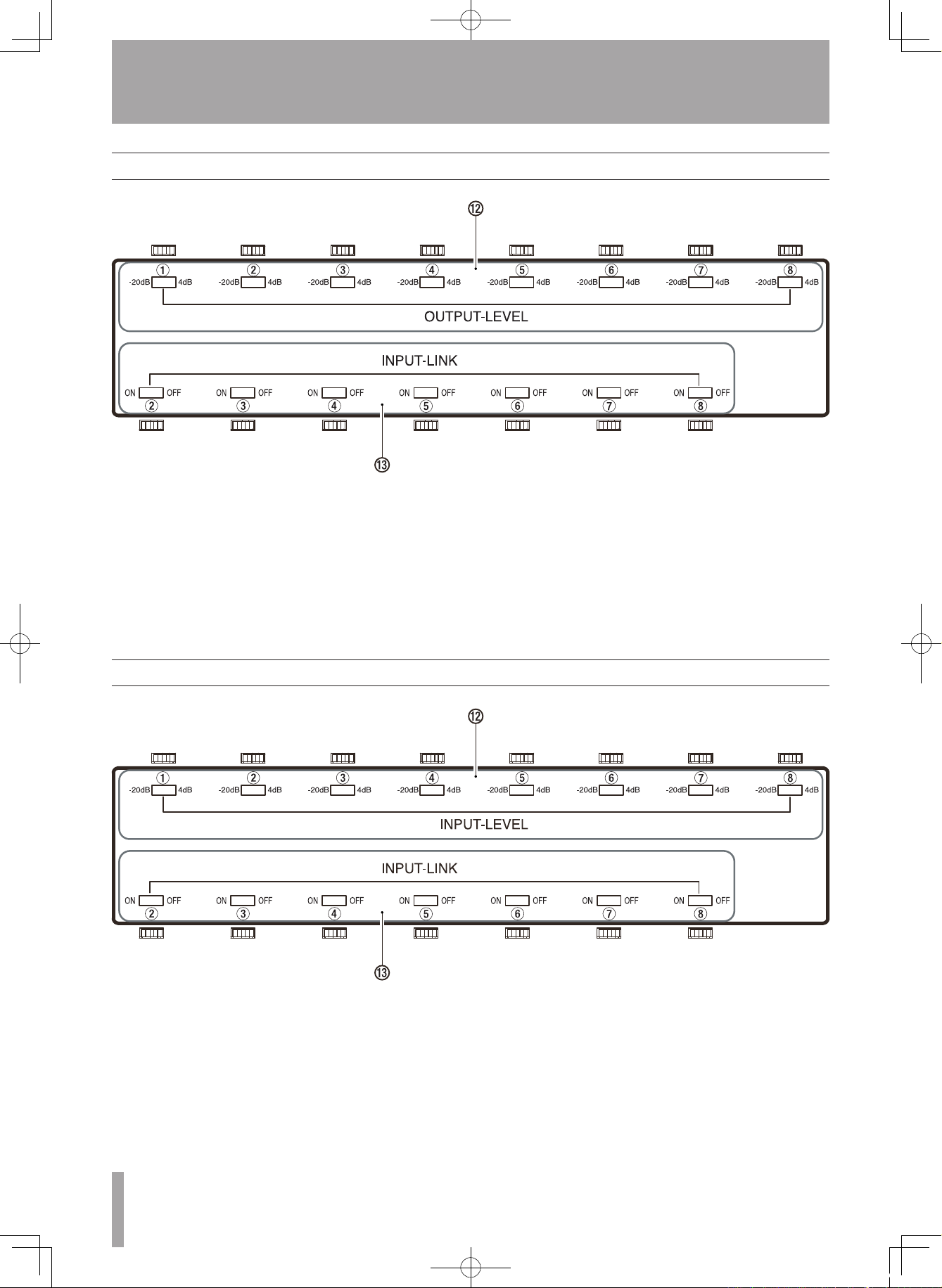
w OUTPUT LEVEL switches 1–8
Switches that set whether the signal levels output
from the OUTPUTS 5 are +4 dBu (1.23 V) or -20
dBu (0.0775 V). This setting can be made for each
channel independently.
e INPUT LINK switches 2–8
These switches allow an input signal to be routed
to any higher numbered output. Two or more
inputs can also be assigned to multiple outputs in
sequence (see “3–ADA Functions” for examples.)
w
INPUT LEVEL switches 1–8
Switches that set whether the signal levels input
to the INPUTS 5 are +4 dBu (1.23 V) or -20 dBu
(0.0775 V). This setting can be made for each
channel independently.
e INPUT LINK switches 2–8
These switches allow an input signal to be routed
to any higher numbered output. Two or more
inputs can also be assigned to multiple outputs in
sequence (see “3–ADA Functions” for examples.)
E_LA-80-81mkII_RevC.indd 8 08.12.19 1:07:25 PM
Page 9
TASCAM LA-80/81MKII 9
2–Names and Functions of Parts
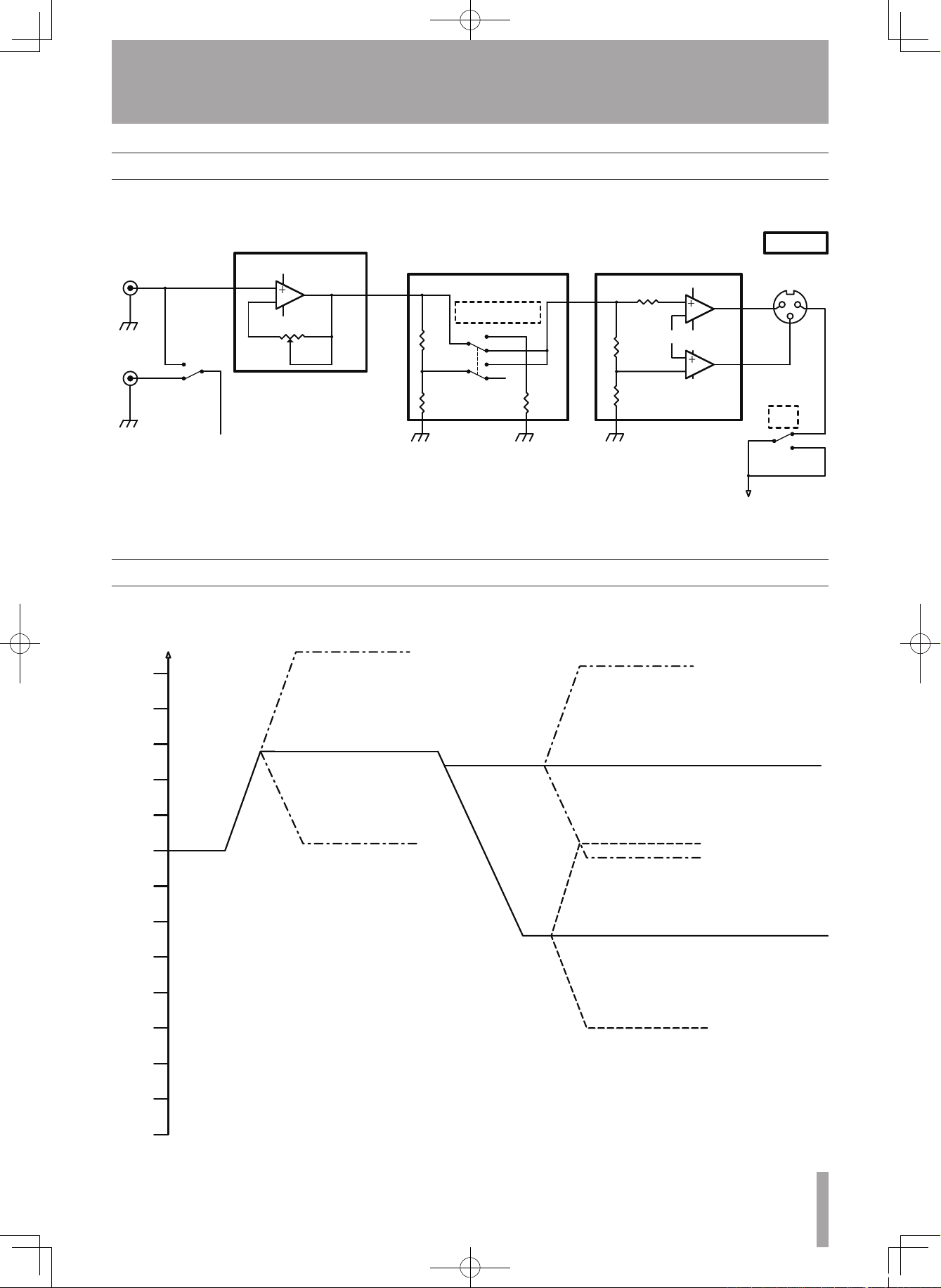
Block diagram (LA-80MKII)
Level diagram (LA-80MKII)
SW
S705
INPUT LINK
RCA JACK
S702
OUTPUT LEVEL
3
2
1
84
−
VR1
J702
NC3FAH1
2
3
1
R729
47k
AGND
AGND
SGND
AGNDAGND
AGND
RCA JACK
GND
LIFT
XLR OUT
+4dBu
-20dBu
+4dBu
-20dBu
LEVEL SHIFT
GND
LIFT
5
6
7
−
−
3
2
1
84
AMP with
TRIM function
BALANCED AMP
LEVEL
-10dBV
-9dBu
-10dB
-5dB
0dB
+5dB
+10dB
+15dB
-15dB
-20dB
-25dB
-30dB
-35dB
-40dB
-45dB
-50dB
+17dBu
+4dBu
-20dBu
+4dBV
-33dBu
(-2.2dB)
(-26.2dB)
+17dBV
-9dBV
0dBu=0.775V
0dBV=1V
-7dBu
UNBALANCED TO BALANCED
UNBALANCED TO BALANCED
E_LA-80-81mkII_RevC.indd 9 08.12.19 1:07:26 PM
Page 10
10 TASCAM LA-80/ 81MKII
2–Names and Functions of Parts
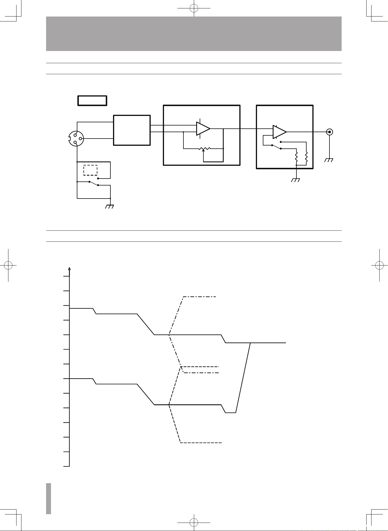
Block diagram (LA-81MKII)
Level diagram (LA-81MKII)
J102
NC3FAH1
2
3
1
SW
U805B
5
6
7
3
2
1
84
−
VR
SW
RCA JAC
K
AGND
AGND
AGND
GND
LIFT
GND
LIFT
XLR IN
BALANCED
INPUT
CIRCUIT
BALANCED AMP
with TRIM function
GAIN SWITCH AMP
+
+
+4dBu
−20dBu
−
LEVEL
-10dB
-5dB
0dB
+5dB
+10dB
+15dB
-15dB
-20dB
-25dB
-30dB
-35dB
-40dB
-45dB
-50dB
+4dBu
+2.1dBu
+8dBu
-18dBu
-31.8dBu
-20dBu
-29dBu
-16dBu
-42dBu
-10dBV
(+24dB)
-5dBu
0dBu=0.775V
0dBV=1V
(-7.1dB)
(-2.8dB)
+21.9dBu
(-7.1dB)
BALANCED TO UNBALANCED
BALANCED TO UNBALANCED
E_LA-80-81mkII_RevC.indd 10 08.12.19 1:07:26 PM
Page 11
TASCAM LA-80/81MKII 11
3–ADA Functions
LA-80MKII ADA Functions
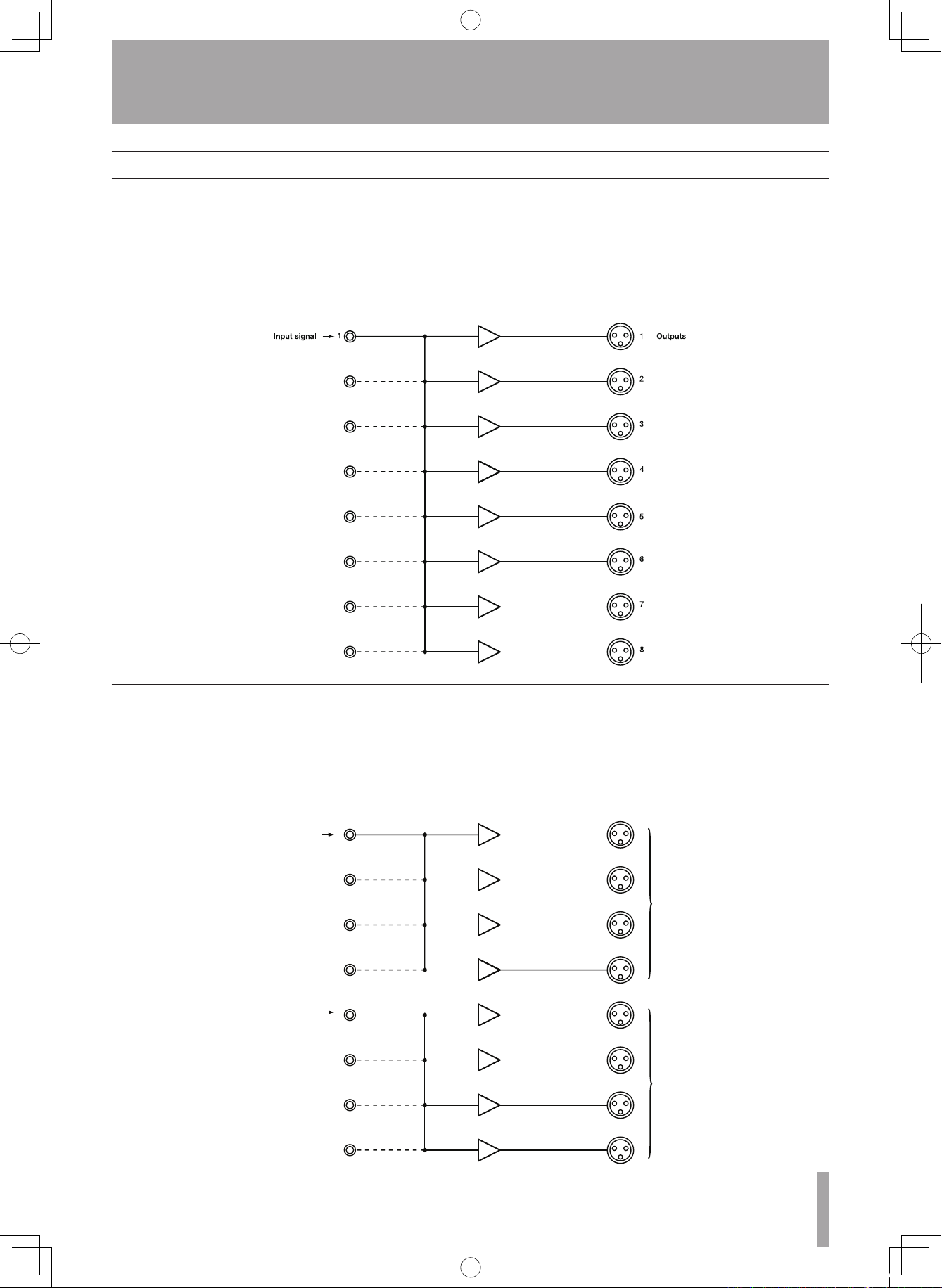
By using the LA-80MKII INPUT LINK switches e, the
signals input from single connectors can be routed to
other channels and output as desired.
In this example, the signal input through channel 1 is
routed to channels 1–8.
1 Input a signal through the (unbalanced) INPUT 1 4.
2 Turn INPUT LINK switches 2– 8 e ON.
3 The signal input through channel 1 is output through
(balanced) OUTPUTS 1–8 5.
Input signal
( L )
Input signal
( R )
1
2
3
4
5
6
7
8
( L )
( R )
Outputs
1
5
In this example, a stereo pair of signals input through
channels 1 and 5 are output in parallel to 4 channels
each.
1 Connect the left stereo signal to the (unbalanced) INPUT 1
4 and connect the right stereo signal to the (unbalanced)
INPUT 5 4.
2 Turn INPUT LINK switches 2– 4 and 6 –8 e ON.
3 The left stereo signal input to channel 1 is output through
(balanced) OUTPUTS 1–4 5, and the right stereo signal
input to channel 5 is output through (balanced) OUTPUTS
5–8 5.
Example 1 (LA-80MKII)
Example 2 (LA-80MKII)
E_LA-80-81mkII_RevC.indd 11 08.12.19 1:07:27 PM
Page 12
12 TASCAM LA-80 /81MKII
3–ADA Functions
LA-81MKII ADA Functions
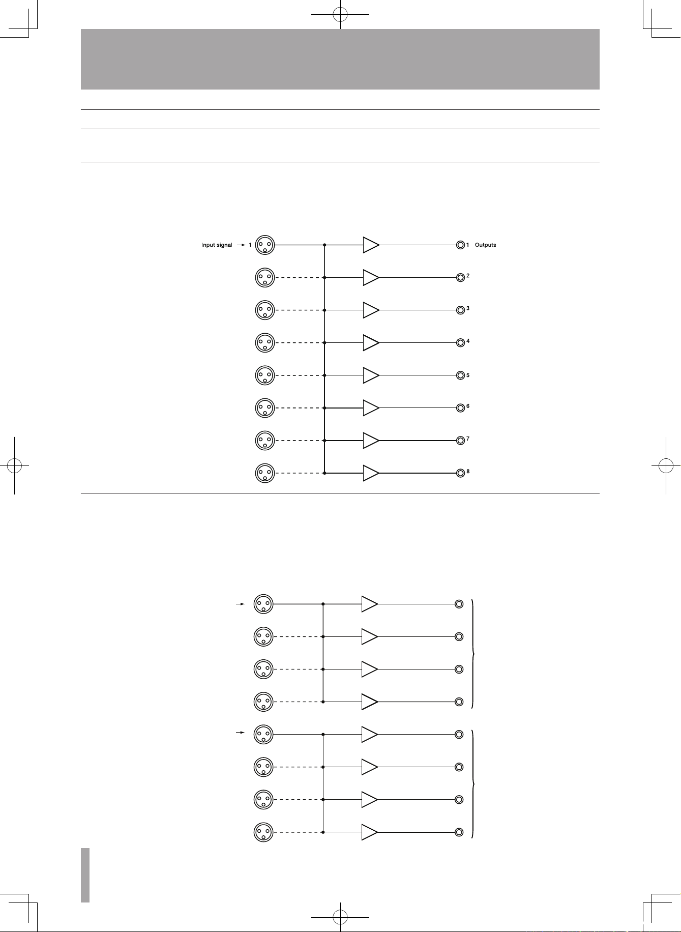
By using the LA-81MKII INPUT LINK switches e, the
signals input from single connectors can be routed to
other channels and output as desired.
In this example, the signal input through channel 1 is
routed to channels 1–8.
1 Input a signal through the (balanced) INPUT 1 5.
2 Turn INPUT LINK switches 2– 8 e ON.
3 The signal input through channel 1 is output through
(unbalanced) OUTPUTS 1–8 4.
( L )
( R )
11
2
3
4
55
6
7
8
( L )
( R )
Input signal
Input signal
Outputs
In this example, a stereo pair of signals input through
channels 1 and 5 are output in parallel to 4 channels
each.
1 Connect the left stereo signal to the (balanced) INPUT 1 5
and the right stereo signal to the (balanced) INPUT 5 5.
2 Turn INPUT LINK switches 2– 4 and 6 –8 e ON.
3 The left stereo signal input to channel 1 is output through
the (unbalanced) OUTPUTS 1–4 4, and the right
stereo signal input to channel 5 is output through the
(unbalanced) OUTPUTS 5–8 4.
Example 1 (LA-81MKII)
Example 2 (LA-81MKII)
E_LA-80-81mkII_RevC.indd 12 08.12.19 1:07:27 PM
Page 13
TASCAM LA-80/81MKII 13
4–Specifications
Inputs and Outputs
UNBALANCED TO BALANCED (LA-80MKII)
Inputs (8 unbalanced RCA pin jacks)
Input impedance 23 kΩ (when all INPUT LINK switches are OFF)
2.8 kΩ (when all INPUT LINK switches are ON)
Nominal input level -10 dBV ±1 dB
Maximum input level +4.8 dBV
Indicator detection level (unbalanced input) –38 dBV or more
(OUTPUT LEVEL switch set to +4 dB or –20 dB)
Outputs (8 balanced XLR type connectors) (Connector holes: 1 = ground, 2 = hot, 3 = cold)
Output impedance 94 Ω
Nominal load impedance 10k Ω
Minimum load impedance 600 Ω
Nominal output level +4 dBu ±1 dB (OUTPUT LEVEL switch set to +4 dB)
-20 dBu ±1 dB (OUTPUT LEVEL switch set to -20 dB)
Maximum output level +23 dBu
BALANCED TO UNBALANCED (LA-81MKII)
Inputs (8 balanced XLR type connectors) (Connector holes: 1 = ground, 2 = hot, 3 = cold)
Input impedance 54 kΩ (when all INPUT LINK switches are OFF)
6.7 kΩ (when all INPUT LINK switches are ON)
Nominal input level +4 dBu ±1 dB (INPUT LEVEL switch set to +4 dB)
-20 dBu ±1 dB (INPUT LEVEL switch set to -20 dB)
Maximum input level +30 dBu (INPUT LEVEL switch set to +4 dB)
+8 dBu (INPUT LEVEL switch set to -20 dB)
Indicator detection level (balanced input) –24 dBu or more (INPUT LEVEL switch set to +4 dB)
–48 dBu or more (INPUT LEVEL switch set to -20 dB)
Outputs (8 unbalanced RCA pin jacks)
Output impedance 200 Ω
Nominal load impedance 10 kΩ
Minimum load impedance 1 kΩ
Nominal output level -10 dBV ±1 dB
Maximum output level +18 dBV
Performance
TRIM range ±12 dB
S/N ratio (nominal input and output level) A-weighting lter + 20 kHz LPF: 90 dB
LA-80MKII (OUTPUT LEVEL switch set to +4 dB)
LA-81MKII (INPUT LEVEL switch set to +4 dB)
20 Hz HPF + 20 kHz LPF: 87 dB
LA-80MKII (OUTPUT LEVEL switch set to +4 dB)
LA-81MKII (INPUT LEVEL switch set to +4 dB)
Total harmonic distortion
(1 kHz, nominal input and output level)
0.007% or less
Frequency response
(nominal input and output level)
20 Hz–100 kHz ±3 dB
Crosstalk -90 dB or more (1kHz, nominal input and output level,
terminated with a 600 Ω load)
E_LA-80-81mkII_RevC.indd 13 08.12.19 1:07:27 PM
Page 14
14 TASCAM LA-80/81MKII
Other specifications
Power: 100-240 V~, 50/60 Hz
Power consumption: 6 W
Weight: 3 kg (main unit)
External dimensions (WxHxD): 482 x 44 x 280 mm
4–Specifications
Dimensional drawings
465mm
280mm
6mm
9mm
44mm
0.5mm
432.6mm
432.2mm
31.8mm
482.6mm
280mm
6mm
9mm
NOTE
In order to improve these units, their specifications •
and external appearance may be changed without
notification.
Please be aware that, as a result of product improve-•
ments, illustrations and other depictions in the Owner’s
Manual may differ in part from the actual product.
E_LA-80-81mkII_RevC.indd 14 08.12.19 1:07:28 PM
Page 15
TASCAM LA-80/81MKII 15
Memo
E_LA-80-81mkII_RevC.indd 15 08.12.19 1:07:28 PM
Page 16

TEAC CORPORATION
www.tascam.jp
Phone: +81-42-356-9143
1-47 Ochiai, Tama-shi, Tokyo 206-8530, Japan
TEAC AMERICA, INC. www.tascam.com
Phone: +1-323-726-0303
7733 Telegraph Road, Montebello, California 90640 USA
TEAC CANADA LTD. www.tascam.com
Phone: +1905-890-8008 Facsimile: +1905-890-9888
5939 Wallace Street, Mississauga, Ontario L4Z 1Z8, Canada
TEAC MEXICO, S.A. de C.V. www.teacmexico.net
Phone: +52-55-5010-6000
Río Churubusco 364, Colonia Del Carmen, Delegación Coyoacán, CP 04100, México DF, México
TEAC UK LIMITED www.tascam.co.uk
Phone: +44-8451-302511
Suites 19 & 20, Building 6, Croxley Green Business Park, Hatters Lane, Watford, Hertfordshire, WD18 8TE, UK
TEAC EUROPE GmbH www.tascam.de
Phone: +49-611-71580
Bahnstrasse 12, 65205 Wiesbaden-Erbenheim, Germany
Printed in China
LA-80@#/81@ #
E_LA-80-81mkII_RevC.indd 16 08.12.19 1:07:28 PM
 Loading...