

NON INT/B
POWER
SIDE
ONE
POWER
SIG.
TM
KS4320/KS4310
(switch and fader models)
Operating manual
POWER
EXT
INT
SIG.
O
N
POWER
EXT
INT
O
N
SIG
.
TALK
BACK
O
F
F
B.T.
SIDE
TONE
NON INT/B
SIDE
TONE
NON INT/B

TM
Table of Contents
Power .............................................................4
Battery operation............................................4
A quick look at the MoniCough...................... 5
Connections................................................. 6
Microphone .....................................................6
Headphones: ................................................... 7
Line output .....................................................7
Monitor/talkback connection ............................7
Some sample setups (side tone)................... 7
Setting up the MoniCough ............................ 9
Talkback and intercom connection ................ 10
Operating the MoniCough ............................. 13
About the fader model (KS4310).................. 14
Specifi cations .............................................. 15
Schematic diagram (KS-4320).........................18
External view (KS4320)................................... 19
Schematic diagram (KS4310).......................... 20
External views (KS4310) ................................. 21
Some troubleshooting tips ........................... 22
About Kamesan............................................ 23
2

TM
Thank you for using the Kamesan MoniCough unit. This provides you with an easy way of muting announcers’ microphone
input, and enabling talkback to and from the producer’s station.
Program monitoring following a number of different industry
standards is also available, as is a sideband facility.
Although the MoniCough is housed in a low-profi le, attractive
case, and has been designed to be simple to operate, there
are a number of “hidden” features that add to its versatility.
We therefore recommend that you read the manual carefully
in order to discover the capabilities of the MoniCough so that
you can set it up to meet the needs of your production environment.
NOTE: There are two models of the MoniCough unit. One, as
described here, uses push-buttons for muting and talkback, and
another model which uses a fader for the same purpose. A brief
description of the fader model is provided in this manual for
reference.
There are also other variants of the MoniCough. There is a
choice of headphone connection, whereby either a stereo 1/4”
jack socket is provided (standard confi guration), or a 7-pin XLR
input may be provided as an option, allowing the connection
of a balanced headset microphone along with the stereo headset.
As well as the basic power connection, the connections to the
MoniCough can be summarized as:
• Microphone input
• Headphone output
• Output to main program mixer
• Output to producer talkback
• Input from producer talkback and intercom system
3

TM
Power
Connect a power supply providing at least 12VDC to the Moni Cough. Suitable power supplies are available from Kamesan.
See the Kamesan Web site or consult your Kamesan dealer
for details. Third party power supplies may be used, provided
they meet the specifi cations provided in this manual. Use of
any other power supply may damage the MoniCough and connected equipment. If in doubt, always check and double-check
the specifi cations.
Battery operation
Alternatively, you may choose to use four AA batteries. Follow
the usual precautions when using batteries:
Always change all batteries together. Do not mix old and
new batteries.
Note the polarity of the batteries as marked in the battery
compartment when inserting batteries.
Do not mix different types of battery (for example, alkaline
and NiCad).
SUM-3
SUM-3
SUM-3
SUM-3
ON
ON
TB SW.
FUNCTION
MONI INT / B
INT / AA
SIDE
TONE
OFF
OFF
TONE
SIDE
Note the two power indicators, one of which is lit when the unit
is turned on, depending on whether battery power (INT) or DC
power (EXT) is being supplied to the unit.
4
TM
POWER
SIG.
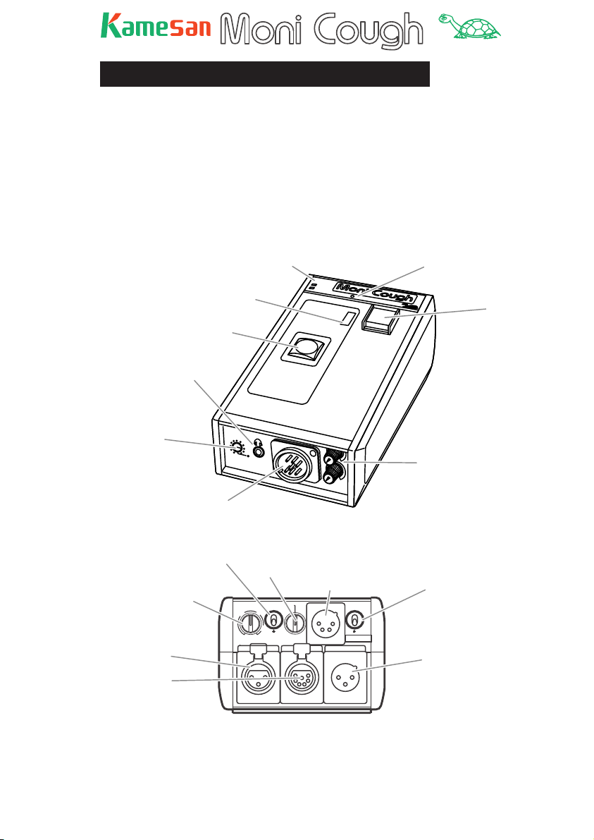
A quick look at the MoniCough
The illustrations below give you a brief guide to the MoniCough’s controls and features.
Note this these drawings show the switch model, fi tted with the
optional XLR-7 connector, which is replaced by a 1/4 -inch stereo jack in the standard model. The bottom panel of the MoniCough is described and illustrated separately as is the fader
model.
Front and top panels
Talk status indicator
Stereo mini-jack
(headphones)
Side tone level
Headset connector
(standard model has
1/4" stereo jack here)
Microphone gain
control
Microphone input
Monitor
input/talkback
output connector
Power indicators
Talk switch
("cough key")
Phantom power
switch
SIDE
TONE
Monitor selection
switch
GAIN
40
35
50
60
30
INPUT
Rear panel
LINE
P48
C-C
1
RTS
MONI / TB
PO
W
ER
EXT
INT
O
N
NON INT/B
Power connector
2
POWER
DC+12V IN
OUTPUT
Signal indicator
SIG.
TALK
BACK
Talkback key
Monitor level controls
Power switch
Output to
program mixer
5
TM
Connections
Microphone
Either:
connect a microphone to the INPUT XLR connector on the rear
panel.
The wiring of this connector follows the 1=ground, 2=hot,
3=cold convention as do all 3 -pin XLR connectors on the MoniCough.
or:
if you have the MoniCough model fi tted with the optional frontpanel 7-pin XLR connector, ensure that your headset is wired in
the way described here before making the connection.
1Ground
2 MIC in (+)
3 MIC in (-)
4 Phones L (+)
5 Phones L (-)
6 Phones R (+)
7 Phones R (-)
IMPORTANT NOTE: The MoniCough can supply +48V
phantom power to the microphone (XLR-3 connection only). Use
the
P48 switch on the rear panel to turn this on, only if you are
connecting a condenser microphone which requires phantom
power. If you have connected any other kind of microphone, do
not turn this switch on.
Use the GAIN control to adjust the microphone signal level so
that the SIGNAL indicator lights. A setting of between 30 and
60 typically gives good results. The small SIG. (signal) indicator
under the “MoniCough” logo lights yellow when a suffi ciently
high post-gain signal is detected.
6

TM
Headphones:
For the stereo jack model, use either the 1/4” jack or 3.5 mm
mini-jack stereo connections on the front panel.
Alternatively, if you have the MoniCough model fi tted with the
optional front-panel 7-pin XLR connector, connect your headset
to the XLR connector. Check that the connections are as described above before making the connection.
Line output
Use the balanced XLR connector to connect the output of the
MoniCough to the mixer input, etc.
Monitor/talkback connection
To connect the MoniCough to the system-wide monitoring and
talkback system, use the MONI/TB connector. The actual wiring
of this connector differs, depending on the paging and talkback
system in use, as selected by the monitor selection switch
above this connector. Make sure that all cables are wired in accordance with your system before making this connection.
This connector carries both the talkback signal(s) from the
booth announcer to the program controller and from the con trol intercom system to the booth announcer.
See the section on monitoring and talkback for full details of
how to use the monitor and talkback connections.
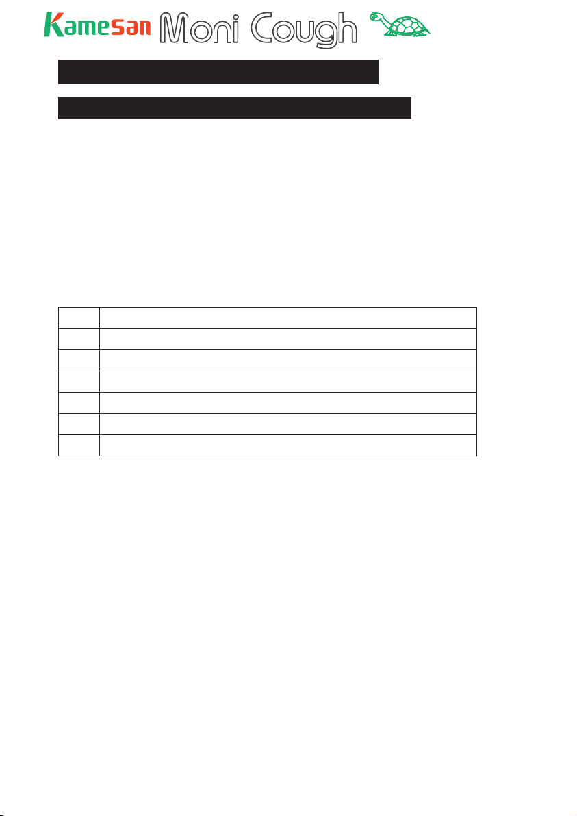
Some sample setups (side tone)
The following illustrate some of the ways in which the MoniCough can be used in different situations using the side tone facility or a feed from the main console, depending on the broadcast setup currently in use:
In the two examples below, one MoniCough unit is deployed
with a separate headset and mic setup, and another with an in tegrated headset/mic. Functionally, these setups are identical,
but the side tone feed is different.
In the fi rst example, side tone is generated using a feed from
the local sources, since there is a minimal time lag between the
signal’s transmission and its reception.
7
TM
BACK
T
ALK
BACK
T
ALK
Program
Inputs from local
sources
Talkback
(paging line)
Monitor
outputs
S
ID
T
O
(L-R)
E
N
E
Facility talkback/paging
Output from MoniCough
(announcer)
P
O
W
E
R
EX
T
I
N
T
S
IG
.
O
N
O
F
F
B
.T.
MONI INT/B
External DC power supply
O
F
F
B
.T
.
S
ID
E
T
O
N
E
Live sources
Ambience
Guide channels
Reporter
P
O
W
E
R
E
X
T
INT
S
IG
.
O
N
MONI IN
T/B
To central station
(master)
Announcer
Guest commentator
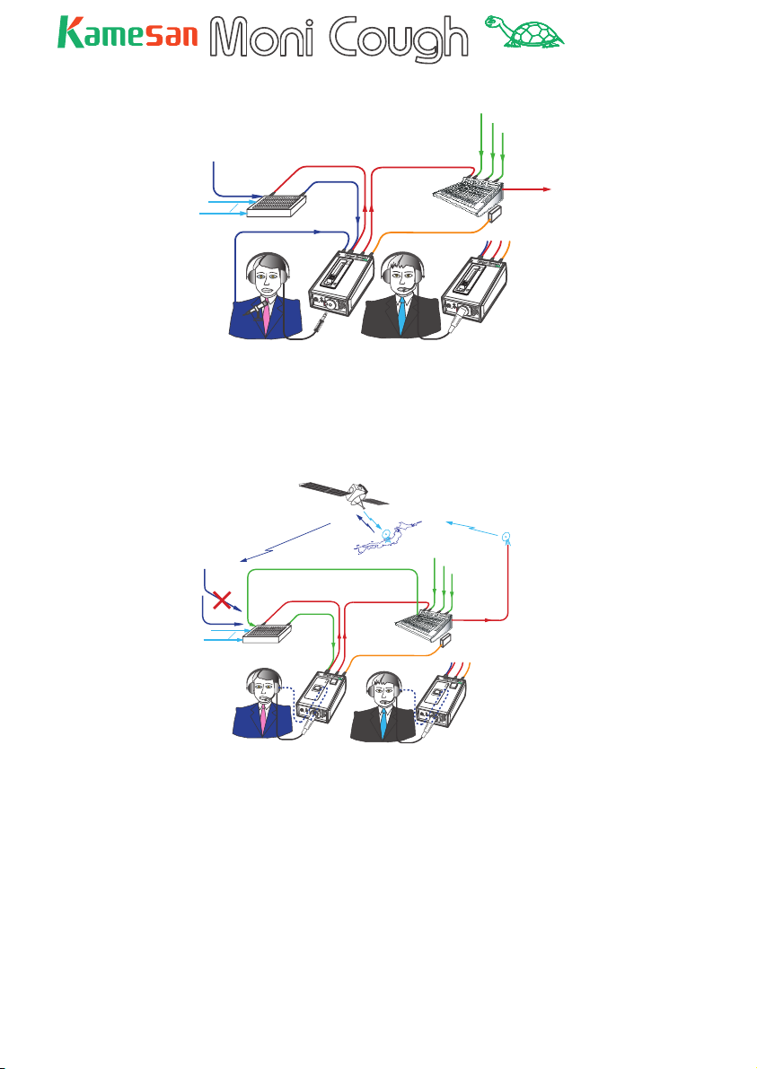
In this second example below, the broadcast signal is transmitted via satellite. Program material is fed back via telephone line to avoid lag, and the headset microphone input is
also fed back in an internal loop to the MoniCough headset.
Sidetone
Satellite uplink
Live sources
Ambience
Guide channels
P
O
W
E
R
E
X
T
I
N
T
SIDE
TO
NE
M
O
N
Reporter
To central station
(master)
S
I
G
.
T
A
L
K
O
B
A
C
K
N
I IN
T
/B
Program
material fed
from landline
Inputs from local
sources
Satellite downink
(not used for
sideband because of
delay)
Facility talkback/paging
Announcer
Ambience, Guide channels, Reporter
Talkback
(paging line)
Sidetone
Output from MoniCough
(announcer)
Monitor
outputs
(L-R)
P
O
W
E
R
E
X
T
I
N
T
S
I
G
.
T
A
L
K
O
B
A
C
K
N
SIDE
TONE
M
O
N
I IN
T
/B
External DC power supply
Guest commentator
When you use the side tone feature in this way, you must enable
it using the switch on the bottom panel (see the next section)
and adjust the volume of this side tone signal with the front
panel control.
8
TM
e
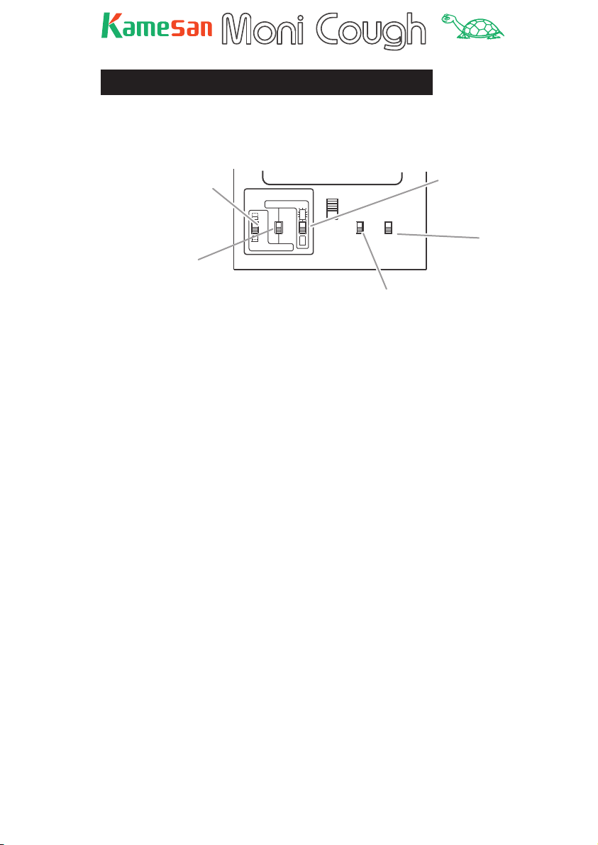
Setting up the MoniCough
The switch settings on the bottom panel allow you to customize
the MoniCough for your particular working style.
Sets mic live or muted
at power-on (nonlatching only)
Latching /
Non-latching
COUGH SWITCH
ALTERNATE
ON
ON
MOMENTARY
O
N
TB SW
FUNCTION
O
N
Enables/disables
talkback switch
ON
OFF
ON
OFF
SIDE
TONE
Sets mic live or muted
at power-on (latching
only)
Enables/disabl
side tone
See the illustration above for details of how these switches are
used. This illustration refers to the switch model (KS4320) of
the MoniCough. The settings for the fader model (KS4310) are
slightly different, and are explained at the end of this manual.
Firstly you can set the “cough key” to be latching (ALTERNATE)
or non-latching (MOMENTARY).
In non- latching mode, the mic can be muted at power-up
(switch in upper position) or live (switch in down position) at
power-up. This effectively allows you to select the cough key as
either a push-to-talk (switch up) or push-to -mute (switch down)
key.
With the cough key in latching mode, you can choose the the
mic to be “on-air”—the ON indicator is lit (switch in upper position) at power-up, or muted—the ON indicator is unlit (switch in
down position) at power-up. Push the cough key to toggle between on-air and muted (as shown by the indicator)
In this bottom panel, you can also fi nd the controls that enable
or disable the TALK BACK key and switch the SIDE TONE on and
off (the use of side tone is explained in the previous section).
NOTE: If the cough key is accidentally left in the muted position
(momentarily) by the announcer, the producer can manually
override the mute with the remote switch function. Note that this
is only available on the switch model, and that remote muting is
not possible.
9

TM
Talkback and intercom connection
As mentioned earlier, the MoniCough is capable of supporting
the common industry-standard intercom formats.
These are selected using the rotary monitor selection switch on
the rear panel of the unit.
Monitor selection switch
LINE
GAIN
35
P48
40
RTS
C-C
1
2
POWER
50
60
30
DC+12V
Note that depending on the switch setting here, the wiring
assignment of the
MONI/TB 7-pin XLR connector on the rear
panel will change. See the specifi cations for full details.
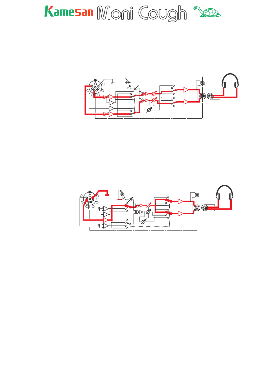
The meaning of the different settings is as follows:
RTS: This switch position uses the RTS IFB system. The Moni -
Cough takes the interrupt and non-interrupt lines and feeds
them to the left and right channels respectively of the headphone system.
Use the INT/A and NON INT/B level controls on the front panel of
the MoniCough to adjust the levels of the interrupt and non-interrupt signals respectively.
for RTS
(0dB/10K)
Using 2 pots
MONI (IFB ) / TB
7
6
1
5
2
4
3
INTERRUPT
NON INTERRUPT
BAL
BA
BA
BAL
RTS(INT.)
RTS(NON-INT.)
SIDE TONE
LINE
INTERRUPT,A
NON INTERRUPT,B
L ch
RTS
RTS
BA
R ch
BA
L
R
These signals are at 0 dB and with an impedance of 10 kΩ.
10
TM
LINE: This switch position allows the MoniCough to take a ste-
reo monitoring signal and feed it to the left and right headphone
outputs.
Use the INT/A control on the front panel to adjust the level of
both channels of the stereo signal.
LINE MONITOR
(0dB/10K)
Using Gang-pot
MONI (IFB ) / TB
7
6
5
4
3
1
2
BAL
BA
BA
BAL
Clear-Com 2-A
Clear-Com 1
LINE(L)
RTS(INT.)
Clear-Com 2-B
Clear-Com 1
LINE(R)
RTS(NON-INT.)
SIDE TONE
LINE
INTERRUPT,A
NON INTERRUPT,B
LINE
LINE
L ch
BA
R ch
BA
L
These signals are at 0 dB and with an impedance of 10 kΩ.
C-C 1: This stands for Clear-Com, type 1, where one signal
is received and split to both the left and right headphone outputs.
Use the INT/A control on the front panel to adjust the signal level
in both headphones.
for Clear-com
(1ch,TR-50 )
( -15dB/10K )
Using Gang-pot
MONI (IFB ) / TB
7
6
5
4
3
1
2
BAL
BA
BA
BAL
SIDE TONE
Clear-Com 1
Clear-Com 1
LINE
INTERRUPT,A
NON INTERRUPT,B
Clear-Com 1
Clear-Com 1
L ch
BA
R ch
BA
L
R
R
This signal is at –15 dB and with an impedance of 10 kΩ.
11

TM
CC 2: This stands for Clear-Com, type 2, where two signals are
received and fed independently to the left and right headphone
channels.
Use the INT/A control to adjust the level of the Clear- Com 2 -A
signal, and the UNINT/B control to adjust the level of the ClearCom 2-B signal.
for Clear-com
(2ch,TR-532 )
( -15dB/10K )
Using 2 pots
MONI (IFB ) / TB
7
6
5
4
3
1
2
BAL
BA
BA
BAL
SIDE TONE
Clear-Com 2-A
Clear-Com 2-B
LINE
INTERRUPT,A
NON INTERRUPT,B
Clear-Com 2-B
Clear-Com 2-A
L ch
BA
R ch
BA
These signals are at –15 dB and with an impedance of 10 kΩ.
L
R
12

TM
Operating the MoniCough
The MoniCough operation depends chiefl y on the settings made
on the bottom panel of the unit.
Basically, the ON switch is used to turn the mic between live
and muted. Whether the switch is latching or non-latching, and
whether the unit is on-air or muted when turned on are determined by the switch settings. See the section on “Setting up the
MoniCough” earlier in this manual for details.
When the TALK BACK key is pressed and the bottom panel
TB SW FUNCTION switch is set to ON, talkback through the intercom system is enabled with the TALK BACK key. If the program
output is not already muted, pressing the TALK BACK key mutes
it. When this switch is OFF, talkback is always enabled (the
TALK BACK key is disabled).
The mic volume is adjusted using the GAIN control (controlling
the program and talkback gain together).
The side tone level is adjusted using the SIDE TONE control on
the front panel (when it has been enabled using the bottom
panel SIDE TONE switch).
The pager/communications feed levels are adjusted on the
MoniCough as explained in the previous section, using the
INT/A (and optionally the NON INT/B) control(s), depending on
the setting of the selector switch.
As a reminder, the switch positions are given again here:
Sets mic live or muted
at power-on (nonlatching only)
Latching /
Non-latching
COUGH SWITCH
ALTERNATE
ON
ON
MOMENTARY
O
N
O
N
TB SW
FUNCTION
ON
OFF
ON
OFF
SIDE
TONE
Sets mic live or muted
at power-on (latching
only)
Enables/disables
side tone
Enables/disables
talkback switch
13

TM
About the fader model (KS4310)
The principal difference between the fader and switch models is
that on the fader model the talk switch and the TALK BACK key
are replaced by a single fader. Note that the illustration here
shows the standard 1/4” headphone jack model.
POWER
EXT
INT
SIG.
O
N
O
F
F
B.T.
SIDE
TONE
NON INT/B
Pushing the fader up enables the microphone and lights the
ON indicator, which therefore acts as an “on air” indicator.
Since the concept of “latching” versus “non-latching” does not
apply here, the different options available through the switches
on the switch model’s bottom panel are not available on the
fader model.
The TALK BACK key’s functionality is achieved by pulling
the fader down (and muting the output) to a non-latching
position where the B.T. Indicator lights (“back talk”). The
TB SWITCH FUNCTION key on the bottom panel is used to enable
or disable this function. When disabled, talkback is always active, regardless of the fader position.
14
TM
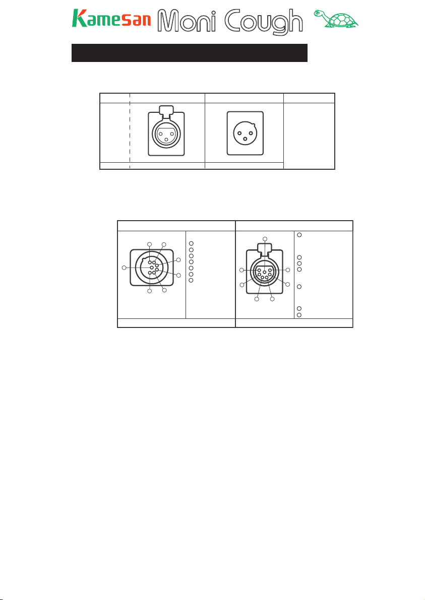
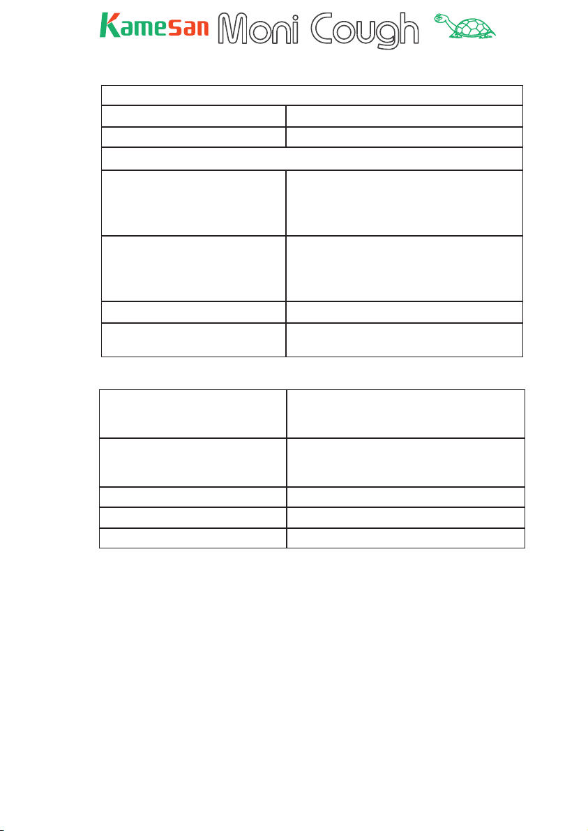
Specifi cations
Connections (input and output XLR-3)
INPUT¥connector ¥¥OUTPUT connector Pinout
2¥HOT
ł Type
¥¥XLR - 3 - 31 ¥¥¥¥¥ XLR - 3 - 32
Plug type XLR - 3 - 12 type XLR - 3 - 11 type
2
1
3
Connections (headset and MONI/TB connectors)
1
2
3
3¥COLD
1¥GROUND
HEADSET Connector ¥¥Pinout¥¥¥¥ ¥¥MONI / TB Connector¥¥Pinout
1
1
2
7
5
6
NC7MDL-B-1¥¥¥¥¥¥¥¥¥¥¥¥¥¥¥¥XLR - 7 - 31
Plug type¥¥¥¥XLR - 7 - 1 1 type¥¥¥¥¥¥¥¥¥¥¥¥¥¥¥XLR - 7 - 12 type
F.G
2
MIC IN ( HOT )
3
MIC IN ( COLD )
3
4
H.P - Left ( HOT )
5
H.P - Left ( COLD )
6
H.P - Right ( HOT )
4
7
H.P - Right ( COLD )
7
6
5
4
1
F.G
RTS * (GROUND )
Clear-com 2 ** (GROUND )
Clear-com 1 *** (GROUND )
2
TALK BACK OUT ( HOT )
3
TALK BACK OUT ( COLD )
4
MONI INPUT - L ( HOT ) or
1
RTS INTERRUPT * or
Clear-com 2-A **
2
5
MONI INPUT - L ( COLD ) or
RTS NON-INTERRUPT * or
3
Clear-com 2-B ** or
Clear-com 1 ***
6
MONI INPUT - R ( HOT )
7
MONI INPUT - R ( COLD )
Note that the MONI/TB connector pinout varies, depending on
the setting of the monitor switch.
In the table above, no asterisk by a pin descriptor means that
the pin retains its function in all modes or that in the case of
multiple functions for that pin, the LINE mode is selected. One
asterisk (*) indicates the RTS setting. Two asterisks (**) show
that this assignment is valid in the CC-2 mode, and three asterisks show the assignment is valid in CC-1 mode.
15
TM
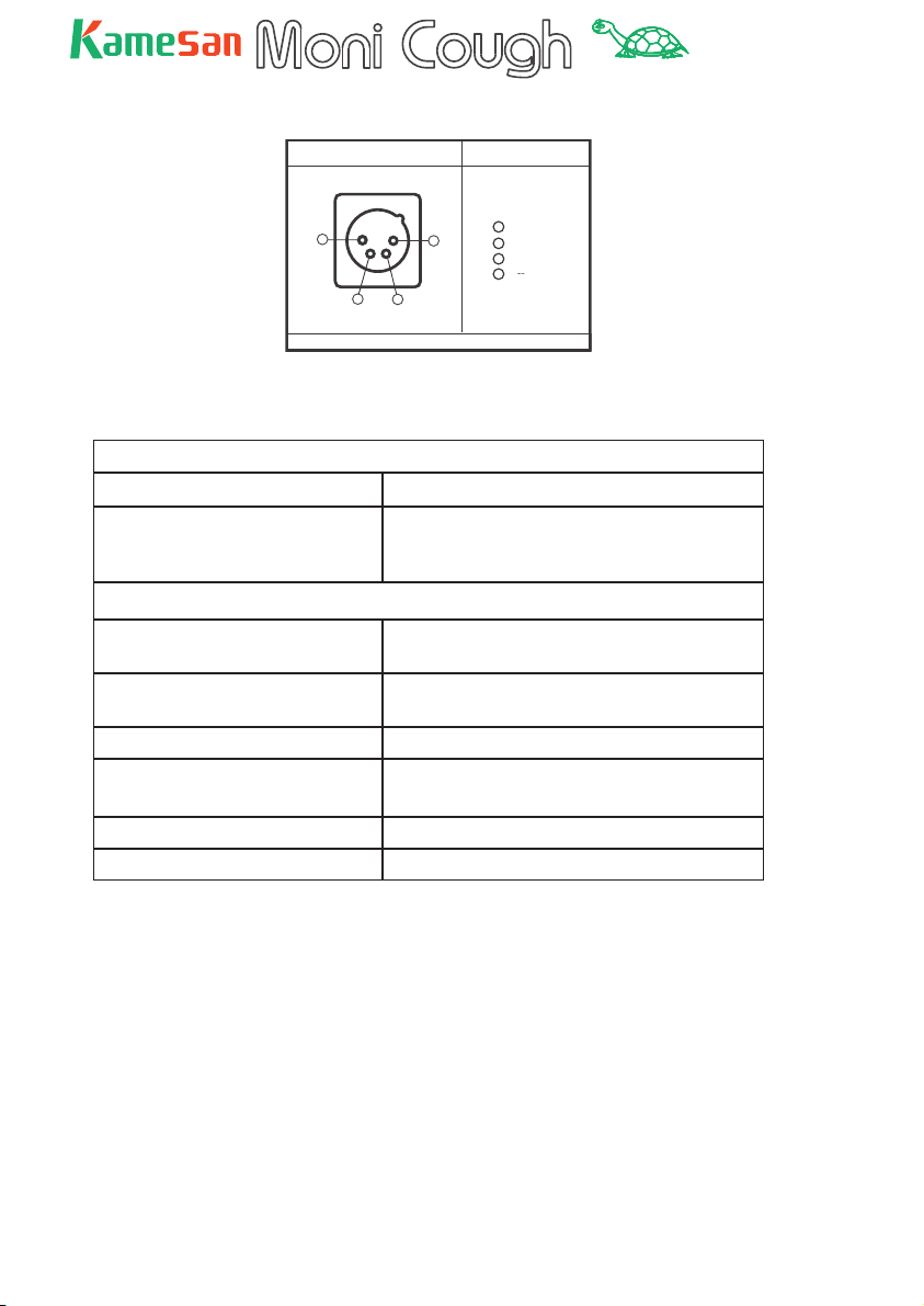
Connections (power input)
DC Input Connector PINassignment
1
1
2
¥NC7MDL-B-1
Plug Type XLR - 4 - 1 1 type
4
3
0 V
2
FU ON OUT
3
N.C.
4
+9¥ +15V
Audio specifi cations
Input
Input impedance 1.2 kΩ (transformer- less ba lanced input)
Input gain 30 dB to 60 dB (60 dB gain setting is equiv-
alent to 0 dB output with an input level of
–62.5 dBs (– 60 dBm)
Output
Output impedance about 34 Ω (under load, transformer-
equipped balanced input)
Output level _20 dBm (with 6 V power supply and a load
of 600 Ω)
Frequency response 50 Hz to 15 kHz +0 dB, – 0.5 dB
Signal-to- noise ratio >62 dB (gain at 60 dB and output of 0 dBm)
>79 dB (gain at 30 dB and output of 0 dBm)
Total harmonic distortion <0.2% (input level > 20 dB)
FU >90 dB (fader and switch models
16
TM
Monitor section
Input
Input impedance 10 kΩ (transformer-less balanced input)
Input level 0 dBs
Output
Output level –10 dBs (with a load of 32 Ω, jack head-
phone type, single signal)
–4 dBs (with a load of 200 Ω, XLR head-
phone connector)
Maximum output level +4 dBs (with a load of 32 Ω, jack head-
phone type, single signal)
–8 dBs (with a load of 200 Ω, XLR head-
phone connector)
Total harmonic distortion <0.2% (input level > 20 dB)
Maximum talkback level (from
MoniCough)
+16 d Bm
Other characteristics
Power supply External power supply (+9 to +15 V – maxi-
mum current 0.4 A), or 4 x type 3 (AA)
batteries
Battery life Better than 5 hours with alkaline batteries
(3 hours with manganese) at normal tem-
perature conditions (20˚C, 68˚F)
Dimensions (w x h x d) 97 x 65 x 160 (mm) 3.8 x 2.6 x 6.3 (in)
Weight (main unit) 1 kg (approx. 2.2 lb) without batteries
Weight (probe) 180 g (including 2 m (>6 ft) cord) (6.5 oz)
17
TM
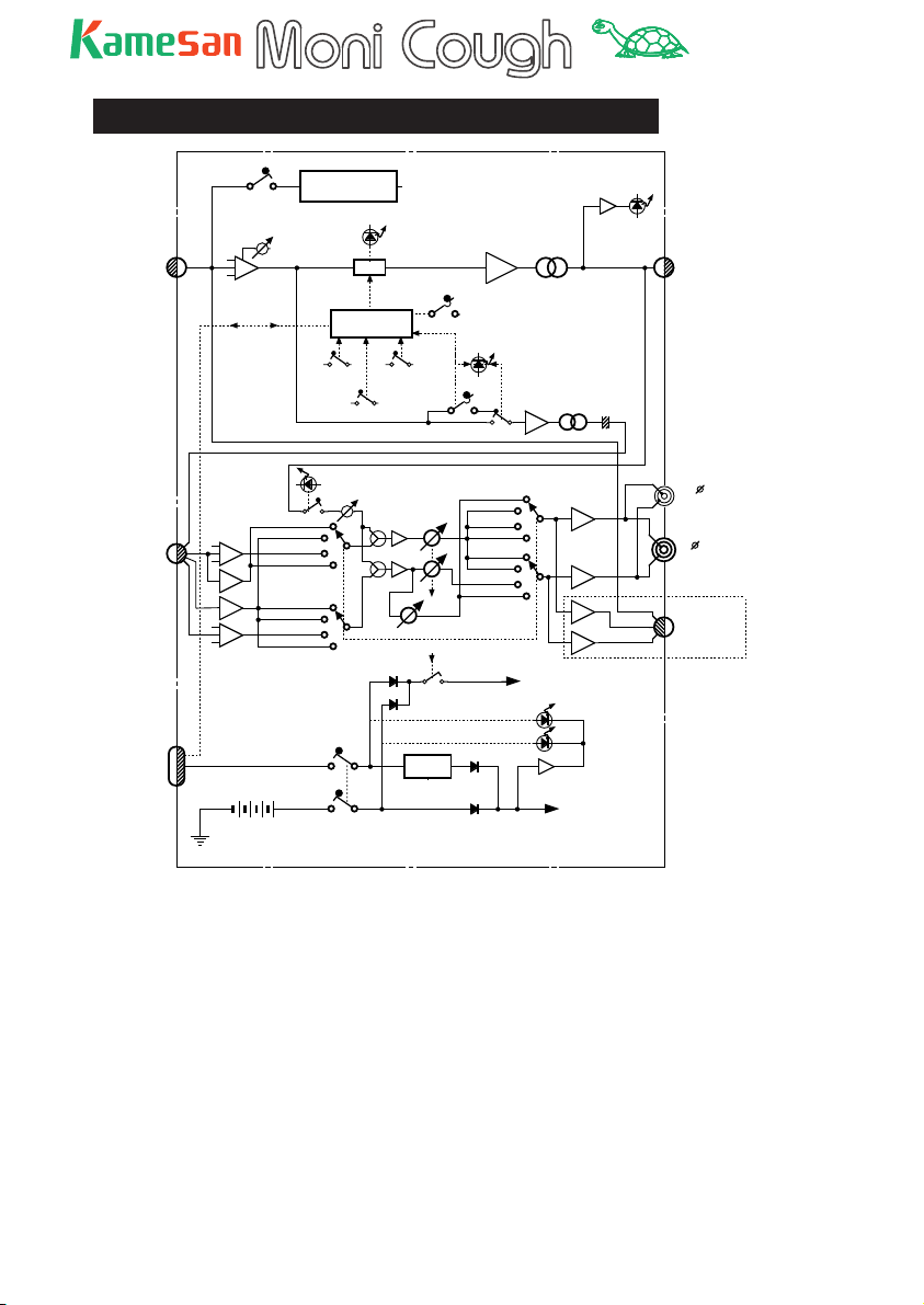
Schematic diagram (KS-4320)
OFF
ON
48V DC - DC CONV.
PHANTOM
INPUT
(3Pin XLR)
INPUT GAIN
HA
ON Tally ON Cont
60~30
MOM.
Key operation
SW
ON Cont.
CONTROL
ALT.
OFF
PUSH ON
PUSH OFF
ON key mode(MOM)
ON
ON
Startup mode (ALT)
TALK BACK SW
COUGH
ON(OFF)key
MUTE
BA
TB ON
ON
OFF
TB SW . FUNCTION
BA
OUTPUT SIGNAL
T
T
TALK BACK
OUTPUT
(3Pin XLR)
MONI (IFB)/TB
(7Pin XLR)
DC IN
&
ON Tally
(4Pin XLR)
BAL
BA
BA
BAL
RTS(NON-INT.)
BATT.(SUM-3X4)
DRY BATTERY
Clear-Com 2-A
Clear-Com 1
LINE(L)
RTS(INT.)
Clear-Com 2-B
Clear-Com 1
LINE(R)
SIDE TONE ON IND.
SIDE TONE
ON
ON
POWER SW
LINE
INTERRUPT,A
NON INTERRUPT,B
MONI. POWER SW
Reg
Clear-Com 2-B
Clear-Com 1
LINE
RTS
Clear-Com 2-A
Clear-Com 1
LINE
RTS
Power IND.
L ch
BA
R ch
BA
BTL
BA
BTL
BA
~+ 14V
MONITOR AMP POWER
EXT.
INT.
Low Volt Det.
~+6V
MIC AMP POWER
MIC
L ch
R ch
3.5
STEREO Mini
HeadPhone
(6 Stereo Jack)
or
OPTION 1
Head Set
(4~7Pin XLR)
OPTION 1
18

TM
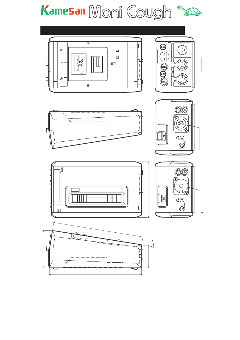
External view (KS4320)
XLR-7 PIN
ASSIGNMENT
IN
DC
4
MONI IN L
MONI IN R
( IFB )
0 V
7 COLD
5 COLD
6 HOT
DC 12V IN
4 HOT
ASSIGNMENT
1
TB OUT
2 HOT
1 GND
3 COLD
TALK
BACK
SIG.
N
O
Moni Cough
INT
EXT
POWER
SIDE
TONE
ON
15V+9
NC
3
(COUGH
2
ON TALLY)
ON
TB SW
FUNCTION
O
ALTERNATE
ON
ON
COUGH SWITCH
OFF
OFF
NON
MOMENTARY
POWER
1
C-C
LINE
RTS
P48
GAIN
IN
DC +12V
OUTPUT
2
MONI / TB
50
40
60
INPUT
30
35
INT / A
SIDE
TONE
INT / A
NON INT / B
NON INT / B
Rear View
Headset ( Option )
( Cannon 7pin )
79
SIDE
TONE
Standard Model
( 6.5 Stereo Phone jack )
158
9
65
40
161
Dec. 12. 2002 T.Takiguchi
19
TM
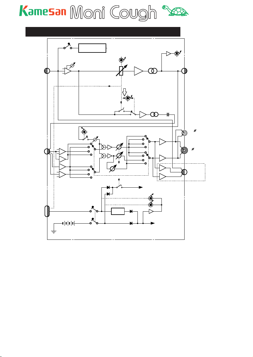
Schematic diagram (KS4310)
OFF
ON
INPUT GAIN
HA
48V DC - DC CONV.
60~30
COUGH
(wiht BT SW)
ON Tally OUT
INPUT
(3Pin XLR)
PHANTOM
ON
TB ON
OUTPUT SIGNAL
BA
T
OUTPUT
(3Pin XLR)
MONI (IFB)/TB
(7Pin XLR)
DC IN
&
ON Tally
(4Pin XLR)
Clear-Com 2-A
Clear-Com 1
BAL
BA
BA
BAL
RTS(NON-INT.)
BATT.(SUM-3ÅX4)
DRY BATTERY
LINE(L)
RTS(INT.)
Clear-Com 2-B
Clear-Com 1
LINE(R)
ON
ON
SIDE TONE ON IND.
SIDE TONE
POWER SW
TB SW. FUNCTION
LINE
INTERRUPT,A
NON INTERRUPT,B
MONI. POWER SW
Reg
ON
OFF
Clear-Com
Clear-Com 2-A
Clear-Com 1
Clear-Com 2-B
LINE
RTS
LINE
RTS
Power IND.
BA
1
T
TALK BACK
L ch
BA
R ch
BA
BTL
BA
BTL
BA
~+ 14V
MONITOR AMP POWER
EXT.
INT.
Low Volt Det.
~+6V
MIC AMP POWER
L ch
R ch
MIC
3.5
STEREO Mini
HeadPhone
(6 Stereo Jack)
or
OPTION 1
Head Set
(4~7Pin XLR)
OPTION 1
20
TM
External views (KS4310)
XLR-7 PIN
ASSIGNMENT
IN
DC
4
MONI IN L
MONI IN R
( IFB )
0 V
7 COLD
5 COLD
6 HOT
DC 12V IN
4 HOT
ASSIGNMENT
1
TB OUT
2 HOT
1 GND
3 COLD
SIG.
N
O
Moni Cough
INT
EXT
POWER
SIDE
TONE
ON
15V+9
NC
3
(COUGH
2
ON TALLY)
OFF
OFF
ON
TB SW
FUNCTION
F
F
O
B.T
79
POWER
C-C
LINE
P48
GAIN
IN
DC +12V
OUTPUT
2
1
MONI / TB
RTS
50
40
60
INPUT
30
35
INT / A
SIDE
TONE
INT / A
SIDE
TONE
NON INT / B
NON INT / B
Rear View
Headset ( Option )
( Cannon 7pin )
Standard Model.
( 6.5 Stereo Phone jack )
158
9
65
40
161
Dec. 12. 2002 T.Takiguchi
21

TM
Some troubleshooting tips
Your voice is not getting through from the microphone to
the program
Are you sure the ON indicator is on? Whether the mic is
live or not at power-up depends on the switch settings on
the bottom panel). In non-latching mode, this determines
whether the cough key is a push-to-talk or push-to-mute key.
Is the GAIN control turned up?
Your voice is not getting through from the microphone
to the producer when press the talkback key (or pull the
fader down)
Is the TB switch on the bottom panel enabled?
Is the GAIN control turned up?
If you cannot hear your own voice in the headphones
Is the side tone switch set on, and is the side tone volume
turned up?
You cannot hear the producer’s voice (or the program
material) in the headphones
Is the correct pager system selected?
Are the INT A (and NON INT B) volume controls turned up?
22

About Kamesan
Sigma Systems Engineering was started in 1972 to develop and
design professional mixers for studio and remote broadcast applications.
Today, following the “slow and steady” principle of the tortoise,
we have built up our sales and our reputation to the extent that
we now enjoy 95% of the Japanese portable mixer market.
We have concentrated on two or three main areas in our design
philosophy: compactness, in an industry which was traditionally dominated by large, heavy equipment; ease of use, since
time is always of the essence in the environments where our
products are used; and quality, to match the needs that today’s
broadcasters require.
Our head offi ce is in Shinjuku, Tokyo, and as a small company,
we are happy to listen to the ideas for product improvement
suggested by you, the customers and users of our equipment.
Making steady progress (like a tortoise, but maybe a little
faster!), we hope to meet your requirements, now and in the
future.
Visit both of our Web sites at http://www.kamesan.co.jp and
http://www.kamesan.info in order to fi nd out more about
what we’re doing, and to let us know what you are doing with
Kamesan products.

Sigma Systems Engineering Co. Ltd.
3-5 -2 Okubo
Shinjuku-ku
Tokyo 169 -0072
JAPAN
Tel: +81 3 3204 2611
Fax: +81 3 3204 2250
e-mail: sales@kamesan.co.jp
 Loading...