

»
IF-SM/DM
Surround Monitor Card
D00885000A
OWNER’S MANUAL
This appliance has a serial number. Please
record the model number and serial number
and retain them for your records.
Model number
Serial number

Contents
1 – Introduction
Installation ............................................ 3
Connections ........................................... 4
Monitor alignment ............................... 4
2 – Using the card
OPERATION option ............................... 5
Muting channels ............................ 5
Soloing channels ............................ 6
Downmix on/off ............................ 6
Bass management ......................... 6
Alternative speakers ..................... 6
Oscillator routing ........................... 6
To 2.1 ............................................. 6
SPL reference and level ................. 6
Notes on other hardware controls ...6
ROUTING option ................................... 7
Monitoring keys ............................ 7
Output routing .............................. 7
DOWNMIX option .................................8
6.1 format ....................................... 9
5.1 format ..................................... 10
LRCS format ................................. 11
Stereo format ............................... 12
BASS MANAGEMENT option .............. 13
Type 1 bass management ........... 13
Type 2 bass management ........... 13
MONITOR ALIGNMENT option ........... 14
Trimming the levels ..................... 14
Generating the pink noise .......... 15
Setting the surround speaker level ...15
Adjusting the LFE GAIN ............... 15
Channel delay .............................. 15
Setting the overall surround level ... 16
3 – Reference
Block diagram ...................................... 17
Level diagram ...................................... 18
Audio performance ............................. 18
Table of figures
Figure 1.1: Fitting the card . . . . . . . . . . . . . . . . . . . . . . . . . . . . . . . . . . . . . . . . . . . . . . . . . . . . . 3
Table 1.2: Pin assignments of the IF-SM/DM analog outputs . . . . . . . . . . . . . . . . . . . . . . . . . . 4
Figure 2.1: The main surround monitor screen . . . . . . . . . . . . . . . . . . . . . . . . . . . . . . . . . . . . . 5
Figure 2.2: The OPERATION option . . . . . . . . . . . . . . . . . . . . . . . . . . . . . . . . . . . . . . . . . . . . . . . 5
Figure 2.3: SHIFTed number keys used for channel control . . . . . . . . . . . . . . . . . . . . . . . . . . . 5
Figure 2.4: ROUTING option screen . . . . . . . . . . . . . . . . . . . . . . . . . . . . . . . . . . . . . . . . . . . . . . 7
Figure 2.5: Example downmix screen showing attenuation points . . . . . . . . . . . . . . . . . . . . . 8
Table 2.6: 6.1 to 5.1 downmix pattern . . . . . . . . . . . . . . . . . . . . . . . . . . . . . . . . . . . . . . . . . . . . 9
Table 2.7: 6.1 to 2.1 downmix pattern . . . . . . . . . . . . . . . . . . . . . . . . . . . . . . . . . . . . . . . . . . . . 9
Table 2.8: 6.1 to stereo downmix pattern . . . . . . . . . . . . . . . . . . . . . . . . . . . . . . . . . . . . . . . . . 9
Table 2.9: 6.1 to mono downmix pattern . . . . . . . . . . . . . . . . . . . . . . . . . . . . . . . . . . . . . . . . . . 9
Table 2.10: 5.1 to phantom rear LRCS downmix pattern . . . . . . . . . . . . . . . . . . . . . . . . . . . . 10
Table 2.11: 5.1 to hard rear LRCS downmix pattern . . . . . . . . . . . . . . . . . . . . . . . . . . . . . . . . 10
Table 2.12: 5.1 to 2.1 . . . . . . . . . . . . . . . . . . . . . . . . . . . . . . . . . . . . . . . . . . . . . . . . . . . . . . . . . 10
Table 2.13: 5.1 to stereo downmix pattern . . . . . . . . . . . . . . . . . . . . . . . . . . . . . . . . . . . . . . . 10
Table 2.14: 5.1 to mono downmix pattern . . . . . . . . . . . . . . . . . . . . . . . . . . . . . . . . . . . . . . . . 11
Table 2.15: LRCS to stereo downmix pattern . . . . . . . . . . . . . . . . . . . . . . . . . . . . . . . . . . . . . . 11
Table 2.16: LRCS to mono downmix pattern . . . . . . . . . . . . . . . . . . . . . . . . . . . . . . . . . . . . . . 12
Table 2.17: LRCS to LRCS with phantom rear downmix pattern . . . . . . . . . . . . . . . . . . . . . . 12
Figure 2.18: Stereo to mono downmix . . . . . . . . . . . . . . . . . . . . . . . . . . . . . . . . . . . . . . . . . . . 12
Figure 2.19: Example downmix screen showing attenuation points . . . . . . . . . . . . . . . . . . . 13
Figure 2.20: Type 1 and Type 2 bass management for 5.1 and 6.1 settings . . . . . . . . . . . . . 13
Figure 2.21: Example downmix screen showing attenuation points . . . . . . . . . . . . . . . . . . . 14
Figure 3.1: Block diagram . . . . . . . . . . . . . . . . . . . . . . . . . . . . . . . . . . . . . . . . . . . . . . . . . . . . . 17
Figure 3.2: Level diagram . . . . . . . . . . . . . . . . . . . . . . . . . . . . . . . . . . . . . . . . . . . . . . . . . . . . . 18
2 TASCAM IF-SM/DM Owner’s Manual
1 – Introduction
The IF-SM/DM card allows the connection of one or two surround monitoring systems. It provides flexible setup capabilities, routing, downmix capabilities, bass management, and monitor
setup, etc. from within the IF-SM/DM’s interface.
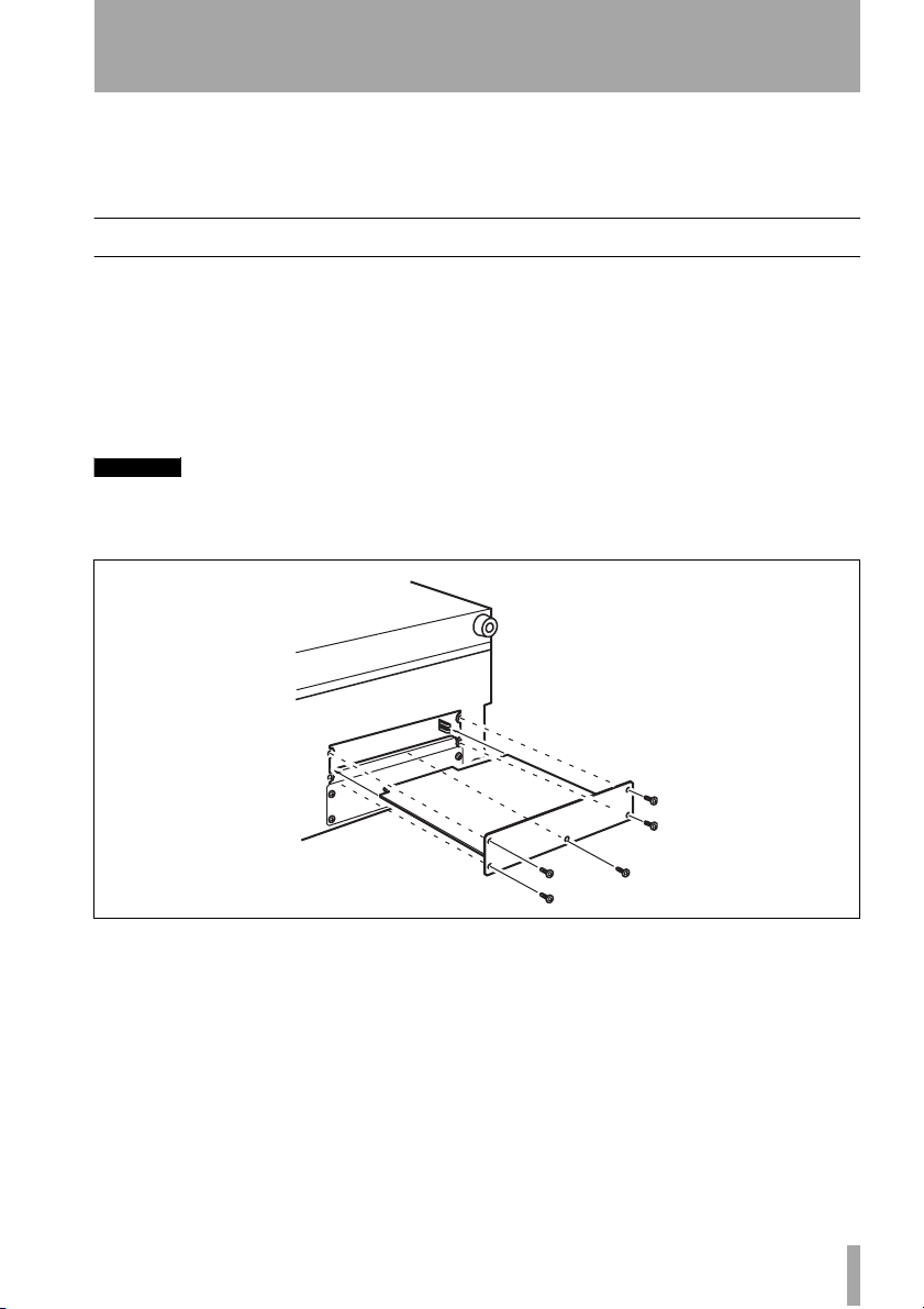
Installation
You should not install or remove cards yourself, but should refer installation to a qualified
TASCAM distributor. Otherwise, the warranty will be voided.
1Turn off the main unit and disconnect
it from the power supply. Disconnect
all other equipment connected to it.
WARNING
The above step is most important. If you do not
do this, there is a risk that you may cause damage
to the main unit as well as to other equipment.
2 Use a screwdriver to remove the blank-
ing panel from the slot into which you
will fit the interface card. Keep the
retaining screws in a safe place.
If you are installing more than one
card, we suggest that you start from the
top slot (slot 1) and work downwards.
Figure 1.1: Fitting the card
Ta ke care, if you are removing a previously-fitted interface card, that you
are removing the retaining screws, and
not the smaller screws which fix the
card to the rear plate. Also, if you are
removing a previously-fitted card, use
the binding posts on the rear plate to
help remove the card.
3 Remove the interface card from the
anti-static protective bag. Hold the
card by the edges, and insert it, component side upwards, into the slot.
Insert the card between the guide rails
and slide it all the way into the slot, as
shown. You may have to push firmly to
plug the card into the internal connector.
4 Locate the card into the connector
inside the main unit. Push the card
firmly, without forcing, so that the connector grips the end of the card.
TASCAM IF-SM/DM Owner’s Manual 3

1 – Introduction : Connections
A new unit’s card slot and/or new card
may be a little stiff. Make sure that the
card is pushed as far as it will go (so
that the card rear connector plate
touches the rear panel of the unit).
5 Use the screws supplied with the card
to attach the rear panel of the interface
card to the rear panel of the unit.
6 Repeat the installation process for all
the interface cards that you are fitting.
• When removing a card, unscrew the
five retaining screws and use the “pull
posts” on the rear panel of the card to
remove it from the unit. There are no
rules governing which interface cards
may be fitted in any of the slots, except
for the IF-FW card, which must be fitted in slot 1—any other interface card
may be fitted in any expansion slot.
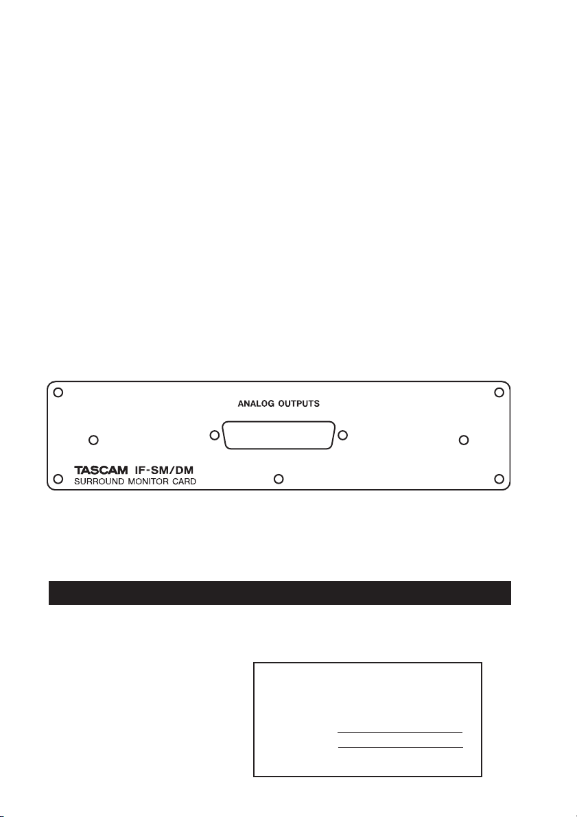
Connections
The D-sub 25-pin connector allows the connection of up to eight balanced analog connections
at +4dBu levels (the impedance is 100Ω).
Pin 1 2 3 4 5 6 7 8 9 10 11 12 13‘
8+ 8Gnd 7– 6+ 6Gnd 5– 4+ 4Gnd 3– 2+ 2Gnd 1– NC
Signal
8– 7+ 7Gnd 6– 5+ 5Gnd 4– 3+ 3Gnd 2– 1+ 1Gnd
Pin 14 15 16 17 18 19 20 21 22 23 24 25
Table 1.2: Pin assignments of the IF-SM/DM analog outputs
Suitable cables can be obtained from most
professional audio suppliers.
Monitor alignment
The card allows each channel to have an individual delay time set in milliseconds, as well
as a trim level.
This is set using the
screen, and the procedure is described later in
this manual (“MONITOR ALIGNMENT
option” on page 14).
MONITOR ALIGNMENT
4 TASCAM IF-SM/DM Owner’s Manual
The overall SPL level can be set (on the
ATION screen), along with the LFE gain.
OPER-
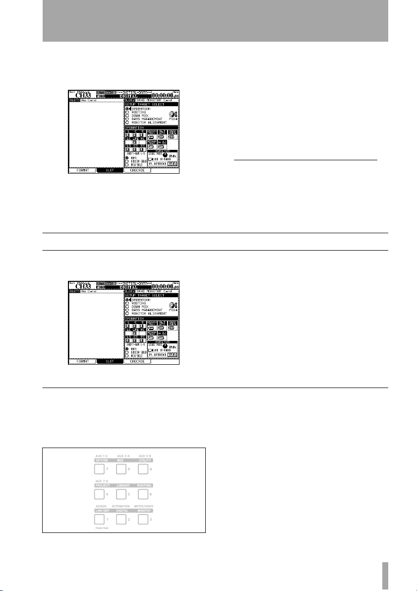
2 – Using the card
You can access the card’s functions by pressing the
DIGITAL key and selecting the SLOT
sub-screen.
Figure 2.1: The main surround monitor screen
OPERATION option
The OPERATION option allows the following
operations to be carried out:
Figure 2.2: The OPERATION option
The surround monitor card is here shown
installed in slot 2.
The top half of this part of the screen shows
the different options (referred to as
GETs), and the lower half shows the settings
SETUP TAR-
for these options.
Use the POD 4 encoder
ferent options available, and the
1
to highlight the dif-
ENTER key
to select the option.
1. Throughout this manual, we assume that
the card is fitted in slot 2. If the card is fitted in slot 1, any reference to POD 4
should be interpreted as referring to POD
2, and any reference to POD 3 should be
interpreted as referring to POD 1.
• Muting of individual channels
• Soloing (exclusive or mixed) of individual
channels
• Switching downmix on and off
• Switching alternative speakers on and off
• Routing the internal oscillator on and off
•Turning bass management on and off
• Instant downmix to a 2.1 setting
• Setting the monitoring level
• Setting SPL reference level
Muting channels
Use the cursor and ENTER keys to select the
MUTE option. Mute the monitoring of individ-
ual channels using the
SHIFTed number keys
as described here:
LCR
LC LFE RC
LS CS RS
Figure 2.3: SHIFTed number keys used for channel control
When a channel is muted, it appears with an
inverse
M on the display. Unmuted channels
show an on-screen “button”.
Note that you can also use the cursor and
ENTER keys to change the mute status.
TASCAM IF-SM/DM Owner’s Manual 5

2 – Using the card : OPERATION option
Soloing channels
This works with the same SHIFTed number
keys as for muting (see Figure 2.3, SHIFTed
number keys used for channel control) as well
as the cursor and
There are two solo options—one for an exclusive solo mode, where only one channel at a
ENTER key options.
Downmix on/off
Use the on-screen DOWN MIX button to turn
downmixing on and off (as set up in the
MIX option) — ignored when the alternative
DOWN
Bass management
Use the on-screen BASS MGT button to turn
bass management on and off (as set up in the
BASS MANAGEMENT option) — ignored when
Alternative speakers
This routes the signal when downmixed to
stereo, to the speakers connected to the LC
and RC channels, which are not used in the
surround patterns.
time is active, and one for a mixed solo mode,
where selected channels are active.
The on-screen solo marks are shown by an S
button, in the same way as the mute buttons are
shown by an
speaker switch, 2.1 switch or oscillator switch
are on.
the alternative speaker switch, 2.1 switch or
oscillator switch are on.
This allows the use of a pair of “large” stereo
speakers together with smaller surround monitors, without the need for repatching.
Naturally, downmix is not possible with this
switch on.
M (they invert when active, etc.).
Oscillator routing
Allows the routing of the mixer’s internal
oscillator to the surround card outputs.
When the oscillator is routed in this way, soloing is automatically changed to exclusive
To 2.1
When on and the current surround mode is 5.1
or 6.1, this setting automatically overrides the
current downmix setting (of course, downmix
is not possible when this switch is on).
USE ST-FADER
If you check “USE ST-FADER”, you can adjust
the Monitor level settings by the Stereo fader.
SPL reference and level
Note that the SPL REFERENCE setting and monitor level settings are made on this page. These
6 TASCAM IF-SM/DM Owner’s Manual
soloing (it reverts to the previous setting when
the oscillator is not routed in this way).
Note that downmix and bass management are
not available when the oscillator is routed in
this way.
When this setting is deactivated, the original
downmix and mode are restored, as is the
mute status of the LFE channel.
are explained further in “MONITOR ALIGNMENT option” on page 14.
2 – Using the card : ROUTING option
Notes on other hardware controls
MONO key
monitoring in surround mode, the
on the control surface is used to turn downmix
on and off (as set up in
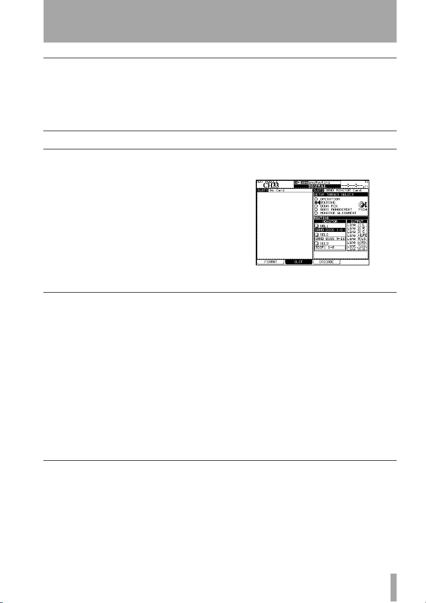
ROUTING option
When the card is being used for
MONO key
DOWN MIX).
DIM key The DIM key on the control sur-
face can be used in the usual way to dim the
outputs from the card. The dimming level is
set in the mixer.
There are two main functions here. The first
allows you to set up the monitoring keys, and
Monitoring keys
The three assignable monitor selection hardware keys in the mixer’s monitoring section
can be set here.
The following can be selected as monitor
sources (stereo):
• Individual Aux busses
•Pairs of Aux busses
• Individual busses
•Pairs of busses
• Digital inputs (1 or 2)
•2 TR analog inputs
• The TDIF signals (1 through 3)
the second allows assignment of the outputs
to the different channels.
Figure 2.4: ROUTING option screen
• The ADAT signal
• The signal of any card in a slot other than
the surround monitor card
In LRCS, 5.1 or 6.1 modes:
• Surround buss 1–8
• Surround buss 9–16
• Digital inputs (1 or 2)
• The TDIF signals (1 through 3)
• The ADAT signal
• The signal of any card in a slot other than
the surround monitor card
Output routing
When a “Line” is referred to in this screen, it is
referring to the analog output line from the IFSM/DM card (as shown in Table 1.2, Pin
assignments of the IF-SM/DM analog outputs)..
The lines can be assigned to the different channels used by the surround pattern currently
selected, differing from the default assignments
made when the surround pattern is selected.
These channels are shown as L, R, C, etc. If a
line output is unused by the pattern, as output
8 is unused in Figure 2.4, ROUTING option
screen, it is shown with the number and
dashes (
-8-).
Note that loopback routing is not possible in
this case (see Figure 3.2, Level diagram).
TASCAM IF-SM/DM Owner’s Manual 7

2 – Using the card : DOWNMIX option
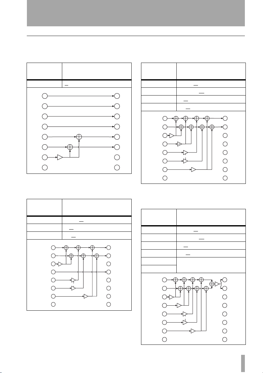
DOWNMIX option
Downmixing is the process of folding a surround mix into a formats using fewer channels. This is done for the purpose of checking
compatibility.
The patterns available depend on the source
format currently in use:
Source
pattern
6.1 5.1
5.1 LRCS (rear phantom center)
LRCS LRCS (rear phantom center)
Available downmix targets
2.1
Stereo
Mono
LRCS (rear hard center)
2.1
Stereo
Mono
source busses are attenuated before they are
folded into the target busses) may be changed.
Figure 2.5: Example downmix screen showing
attenuation points
Attenuation In the on-screen display, the
attenuation points are shown as inverted numbers.
At the bottom of the screen, the values of
these points can be viewed and set using the
cursor keys, dial, and
NOTE
Note that some busses may pass through more
than one attenuator before reaching their destination.
ENTER key.
Stereo
Mono
Stereo Mono
Depending on the value picked here, the other
values (that is, the amount by which the
8 TASCAM IF-SM/DM Owner’s Manual
2 – Using the card : DOWNMIX option
6.1 format
6.1 > 5.1 In the 6.1 to 5.1 downmix, the
attenuation values are:
Source > Target
CS (LC)>LS,RS -3, –4.5, –6
L
R
C
LFE
LS
RS
CS (LC)
RC
Table 2.6: 6.1 to 5.1 downmix pattern
6.1 > 2.1 In the 6.1 to 2.1 downmix, the
attenuation values are:
Source >
Target
C > L,R 0, –1.5, –3, –4.5, –6
LS,RS>L,R 0, –3
CS (LC)>L,R –3, –6
L
R
C
LFE
LS
RS
CS (LC)
RC
Table 2.7: 6.1 to 2.1 downmix pattern
Values in dB (default
–3
–3, –4.5, –6
Values in dB (default
, –6, –∞
, –9, –∞
–3
0, –1.5, –3, –4.5, –6
–3
0, –3, –6, –inf
–3
–3, –6, –9, –inf
underscored)
mute
mute
underscored)
mute
mute
mute
mute
–6
mute
L
R
C
LFE
LS
RS
LC
RC
6.1 > stereo In the 6.1 to stereo downmix,
the attenuation values are:
Source >
Target
C > L,R 0, –1.5, –3, –4.5, –6
L
R
C
LFE
LS
RS
LC
RC
LFE>L,R –3, –6, –9, –
LS,RS>L,R 0, –3, –6, –∞
CS (LC)>L,R –3, –6
L
R
–3
C
0, –1.5, –3, –4.5, –6
LFE
LS
RS
CS (LC)
RC
Table 2.8: 6.1 to stereo downmix pattern
Values in dB (default
underscored)
, –9, –∞
–3, –6, –9, –inf
–3
0, –3, –6, –inf
–3
–6
–3, –6, –9, –inf
∞
6.1 > mono In the 6.1 to mono downmix,
the attenuation values are:
Source >
Target
C > L+R 0, –1.5, –3, –4.5, –6
LFE>L+R –3, –6, –9, –
LS,RS>L+R 0, –3, –6, –∞
CS(LC)>L+R –3, –6
L > L
R > R
L
R
–3
C
0, –1.5, –3, –4.5, –6
LFE
LS
RS
CS (LC)
RC
Table 2.9: 6.1 to mono downmix pattern
TASCAM IF-SM/DM Owner’s Manual 9
Values in dB (default
underscored)
∞
, –9, –∞
summed and attenuated (–3)
–
inf
–3, –6, –9, –inf
–3
0, –3, –6, –inf
–3
–6
–3, –6, –9, –inf
mute
mute
mute
mute
mute
mute
mute
mute
mute
mute
mute
mute
L
R
C
LFE
LS
RS
LC
RC
L
–3
R
C
LFE
LS
RS
LC
RC

2 – Using the card : DOWNMIX option
5.1 format
5.1 > LRCS (rear phantom) In the 5.1
to LRCS downmix with a phantom rear
speaker, the attenuation values are:
Source >
Target
LFE >C –3, –6, –9, –∞
LFE>L,R –3, –6, –9, –∞
LS>LS
RS>RS
L
R
C
–
–3, –6, –9, –inf
LFE
LS
RS
LC
RC
Table 2.10: 5.1 to phantom rear LRCS
Values in dB (default
underscored)
summed and attenuated (–3)
–
inf
inf–inf
–3, –6, –9, –inf
–3
downmix pattern
mute
mute
mute
L
R
C
LFE
LS
RS
LC
RC
5.1 > LRCS (rear hard) In the 5.1 to
LRCS downmix with a hardware rear speaker,
the attenuation values are:
Source >
Target
LFE >C –3, –6, –9, –∞
LFE>L,R –3, –6, –9, –∞
LS>S
RS>S
L
R
C
–inf
–3, –6, –9, –inf
LFE
LS
RS
LC
RC
Table 2.11: 5.1 to hard rear LRCS downmix pattern
Values in dB (default
underscored)
summed
–inf –inf
–3, –6, –9, –inf
mute
mute
mute
mute
L
R
C
LFE
LS
RS
S
RC
10 TASCAM IF-SM/DM Owner’s Manual
5.1 > 2.1 In the 5.1 to 4.1 downmix, the
attenuation values are:
Source >
Target
C >L,R 0, –1.5, –3, –4.5, –6
LS, RS> L, R 0, –3
L
R
–3
C
0, –1.5, –3, –4.5, –6
LFE
LS
RS
LC
RC
Table 2.12: 5.1 to 2.1
5.1 > stereo In the 5.1 to stereo downmix,
the attenuation values are:
Source >
Target
C >L,R 0, –1.5, –3, –4.5, –6
LS,RS>L,R 0, –3
LFE > L,R –3, –6, –9, –∞
L
R
–3
C
0, –1.5, –3, –4.5, –6
LFE
–3, –6, –9, –
LS
RS
LC
RC
Table 2.13: 5.1 to stereo downmix pattern
Values in dB (default
underscored)
, –6, –∞
–3
0, –3, –6, –inf
–3
Values in dB (default
underscored)
, –6, –∞
–
–3
0, –3, –6, –
–3
mute
mute
mute
mute
mute
mute
mute
mute
mute
mute
mute
L
R
C
LFE
LS
RS
LC
RC
L
R
C
LFE
LS
RS
LC
RC

2 – Using the card : DOWNMIX option
5.1 > mono In the 5.1 to mono downmix,
the attenuation values are:
Source >
Target
C > L+R 0, –1.5, –3, –4.5, –6
LFE>L+R –3, –6, –9, –
LS,RS>L+R 0, –3, –6, –∞
L > L
R > R
Values in dB (default
underscored)
∞
summed and attenuated (–3)
L
R
C
LFE
LS
RS
LC
RC
–3
0, –1.5, –3, –4.5, –6
–inf
–3, –6, –9, –inf
0, –3, –6, –inf
–3
–3
mute
mute
mute
mute
mute
mute
L
–3
R
C
LFE
LS
RS
LC
RC
Table 2.14: 5.1 to mono downmix pattern
LRCS format
A control room set up for 5.1 can be set up to
use an LRCS configuration without repatching the speakers. This is possible, since the LS
and RS speakers are assigned the same signal,
thereby creating a “phantom” CS speaker
(attenuated by 3dB).
The default is the LRCS rear hard speaker
configuration, where the LS(S) signal is
assigned to the CS speaker of a 6.1 configuration (not shown above).
LRCS > stereo In the LRCS to stereo
downmix, the attenuation values are:
Source >
Target
C >L,R 0, –1.5, –3, –4.5, –6
S(LS)>L,R 0, –3
L
R
C
LFE
S (LS)
RS
LC
RC
Values in dB (default
underscored)
, –6, –∞
–3
0, –1.5, –3, –4.5, –6
–3
0, –3, –6, –inf
L
R
C
LFE
LS
RS
LC
RC
Table 2.15: LRCS to stereo downmix pattern
TASCAM IF-SM/DM Owner’s Manual 11

2 – Using the card : DOWNMIX option
LRCS > mono In the LRCS to mono down-
mix, the attenuation values are:
Source >
Target
C >L+R 0, –1.5, –3, –4.5, –6
S(LS)>L+R 0, –3
L > L
R > R
L
R
C
0, –1.5, –3, –4.5, –6
LFE
S (LS)
RS
LC
RC
Table 2.16: LRCS to mono downmix pattern
Values in dB (default
underscored)
, –6, –∞
summed and attenuated (–3)
–3
–3
0, –3, –6, –
–3
mute
mute
mute
mute
mute
mute
L
R
C
LFE
LS
RS
LC
RC
Stereo format
Stereo > mono In the LR to mono down-
mix, there are no parameters (changeable
attenuation values).
The left and right signals are summed, and
attenuated by 3dB.
LRCS > LRCS (phantom) In the LRCS
to LRCS with a phantom center rear speaker,
the attenuation values are:
Source >
Target
S (LS) > LS+RS –3 (fixed)
L
R
C
LFE
S (LS)
RS
LC
RC
Table 2.17: LRCS to LRCS with phantom rear
Values in dB (default
underscored)
–3
downmix pattern
mute
mute
mute
L
R
C
LFE
LS
RS
S
RC
LC
RC
L
R
C
LFE
LS
RS
–3
mute
mute
mute
mute
mute
mute
L
R
C
LFE
LS
RS
LC
RC
Figure 2.18: Stereo to mono downmix
12 TASCAM IF-SM/DM Owner’s Manual

2 – Using the card : BASS MANAGEMENT option
BASS MANAGEMENT option
The BASS MANAGEMENT screen allows the
selection of one of two bass management
techniques, Type 1 and Type 2.
Figure 2.19: BASS MANAGMENT option screen
Figure 2.20: Type 1 and Type 2 bass management for 5.1 and 6.1 settings
Type 1 bass management
There are three parameters:
1 The amount of attenuation supplied to the
LFE channel before bass management occurs,
either –5dB (default) or 10dB.
These are illustrated graphically below as they
are implemented in 5.1 surround mode.
2 The amount of attenuation applied to the
surround-LFE feed, either –15dB (default) or
0dB.
3 The crossover frequency of the high-pass
filters applied to all channels except the LFE,
and the low-pass filter applied to the LFE.
From 40Hz (default) to 130Hz in 10Hz steps.
Type 2 bass management
There are two parameters:
1 The crossover frequency of the high-pass
filters and the low-pass filter in the system.
From 40Hz (default) to 130Hz in 10Hz steps.
2 Turns the LFE ON or OFF (default).
TASCAM IF-SM/DM Owner’s Manual 13

2 – Using the card : MONITOR ALIGNMENT option
MONITOR ALIGNMENT option
This allows the setup of the surround speakers
and levels.
Figure 2.21: MONITOR ALIGNMENT option screen
Trimming the levels
When monitoring in surround mode, it is
important that the perceived level of each
channel (as perceived from the monitoring
position) is equal, in order to achieve a satisfactory mix.
NOTE
Before proceeding further with these operations,
it is important that you ensure that the input
mode of the card reflects the setup you are using
and the output channels so that the channels correspond to the actual channels that you have set
up in your system (if the channel meant to be
driving the LFE is actually driving one of the surround channels, you will have severe problems!).
Use the “ROUTING option” on page 7 for
this.
Use the mixer’s oscillator set up to supply
pink noise to allow you to set up and calibrate
your monitoring system for optimal results.
You will also need an SPL (sound pressure
level) meter. Absolute accuracy in this case is
not of prime importance—relative levels are
what are being set up here.
There are two standard weightings that are
commonly used, and may be selected from
most SPL meters: the “C” weighting, providing an almost uniform response from 32Hz to
10kHz, and the “A” weighting, which is concentrated on the 500Hz to 10kHz range. For
full-range music productions, use the “C”
weighting.
TIP
When you make the measurements described
here, either stand the SPL meter on a tripod
(ideal), or hold it to one side of your body, to
avoid reflections, etc. caused by your body which
can affect the final results.
14 TASCAM IF-SM/DM Owner’s Manual

2 – Using the card : MONITOR ALIGNMENT option
Generating the pink noise
Make sure that your monitoring system is
turned on, and adjusted to a reasonable working level.
1 Use the
2 Set the level. If you are working to the
3 Route the oscillator to the surround
MONITOR / OSC/COM screen to set
up the oscillator to produce pink noise.
SMPTE standard,
the analog nominal level (the EBU
equivalent is
busses (“Oscillator routing” on page 6).
Solo (exclusive solo is set by default
when the oscillator is routed this way)
the first channel using the solo controls
on the
OPERATION screen (“Soloing
channels” on page 6).
-20 corresponds to
-18).
Setting the surround speaker level
It is also possible to adjust the level of the
subsidiary speakers on this
MENT screen using the SURROUND LEVEL control.
The speakers adjusted in this way are:
MONITOR ALIGN-
LRCS S speaker only
TIP
When working with 5.1, start the procedures using the C (dialog) channel.
4 Read the level on the SPL meter.
5 Solo another channel. Read the level on
the SPL meter, and adjust the
value shown on the
MONITOR ALIGN-
MENT screen, if necessary, so that it
matches the first.
Trim levels can be adjusted ±9.9dB in
0.1dB steps.
6 Repeat this process until the levels of
all channels, as measured by the SPL
meter, are within a few dB of each
other.
7Turn off the oscillator.
5.1 LS, RS
6.1 LS, RS, CS
These can be adjusted from 0dB to +10dB in
1dB steps.
TRIM
Adjusting the LFE GAIN
The gain of the LFE channel relative to the
other channels can be adjusted using the
GAIN control on this screen. This is indepen-
dent of the surround mode selected.
LFE
Channel delay
To allow for placement, etc. and to prevent
phase distortion, etc., channels can be delayed
relative to each other.
The adjustment is either 0dB (no adjustment)
or +6dB to +10dB in 1dB steps.
Channel delays can be set from 0ms to
50.0ms in 0.1ms steps.
The exact technique of measurement and correction procedures is a little beyond the scope
of this manual.
TASCAM IF-SM/DM Owner’s Manual 15

2 – Using the card : MONITOR ALIGNMENT option
Setting the overall surround level
This is set on the OPERATION screen after the
channels have been aligned. For movie work,
this is standardized at 85dBC, and for television at 82dBC
may use a higher reference level.
1Turn down the level of the monitoring
system.
2 Set the value of the desired reference
level on the
1
. Musical program material
SPL REFERENCE field of the
OPERATION screen.
3 Use POD 3 (or POD 1, as explained
earlier) to set the level to the desired
reference level.
4 Route the oscillator (pink noise) at
nominal level through the surround
system (all channels).
1. The term “dBC” refers to the “C”
weighting average mentioned earlier.
5 Adjust the amplification system so that
the SPL meter located at the listening
position reads 85dB.
Now the POD 3 control can be used to reduce
the monitoring level. Only increase the level if
the material permits.
• The monitor level can be set from 0dbC to
65dBC in 5dB steps, and from 65dBC to
109dBC in 1dB steps.
• The SPL reference level can be set from
65dBC to 109dBC in 1dB steps.
NOTE
At SMPTE standards, there is 20dB of headroom,
so the SPL can be at 105dB before distortion
occurs.
16 TASCAM IF-SM/DM Owner’s Manual
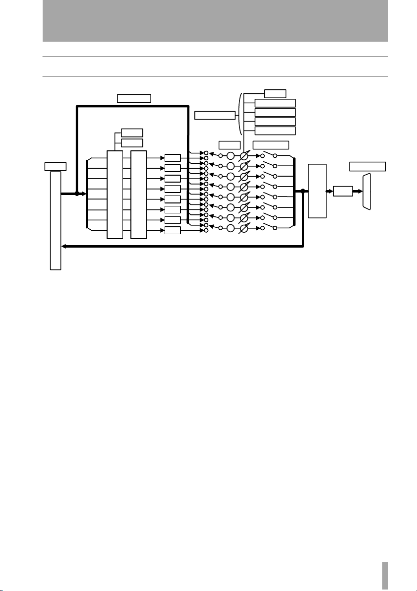
Block diagram
OSC ROUTE
ALT SPK
to 2.1
L
Slot I/O
R
C
LFE
LS
RS
LC
RC
DOWN MIX
L
R
BASS MANAGEMENT
C
LFE
LS
RS
LC
RC
Level Section
Dimmer
Delay
Delay
Delay
Delay
Delay
Delay
Delay
Delay
P
P
P
P
P
P
P
P
Figure 3.1: Block diagram
3 – Reference
dB
TRIM
L
R
C
LFE
LS
RS
LC
RC
dB
dB
dBc
dBc
Output Select
Surround Level
LFE Level
SPL Reference
Moniotr Level
MUTE/SOLO
ANALOG
DAC
TASCAM IF-SM/DM Owner’s Manual 17
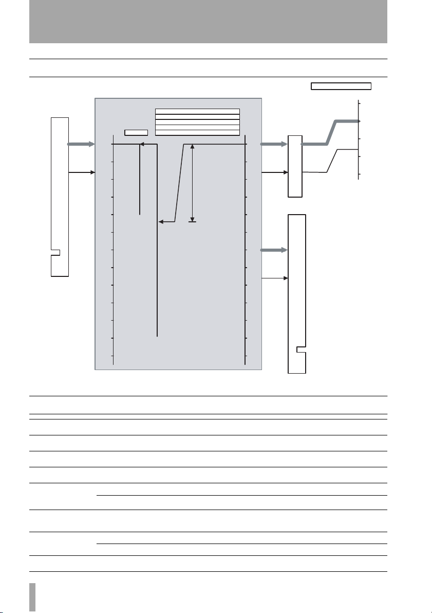
3 – Reference : Level diagram
Level diagram
0dBFs
-16dBFs
IF-SM/DM
[dBFs]
0
-10
-20
-30
-40
-50
-60
DIMMER
-40dB
Trim:-9.9dB...+9.9dB
Surround level: -10dB...0dB
LFE gain:0dB, +6dB...+10dB
SPL reference level: 65dBc...109dBc
Monitor level: 0dBc...109dBc
+44dB
From Card Edge
[dBFs]
0
-10
-20
-30
-40
-50
-60
0dBFs
-16dBFs
0dBFs
+7.16dBu
DAC
-8.84dBu
To Card Edge
MONITOR O UTPUT1-8
BALANCE
+20dBu
[dBu]
+4dBu
+30
+20
+10
0
-10
-70
-80
-90
-100
-110
-120
Audio performance
Maximum level
Nominal level
Output impedance
S/N
Frequency
response
THD
Signal delay
X talk
+20dBu -
+4dBu -
100 Ω -
< –100 dB 2TR IN to MONITOR OUTPUT 1-8, Fs=48kHz
±0.5 dB
+0.5 dB/–1.5 dB
<0.008%
< 1.5 ms Fs = 48.0kHz, LINE to MONITOR OUTPUT 1-8
< 0.75 ms Fs = 96.0kHz, Mixer internal oscillator to MONITOR OUTPUT 1-8
> 90 dB
-70
-16dBFs
-80
-90
-100
-109dB
-110
-120
Figure 3.2: Level diagram
20Hz - 20kHz LINE IN to MONITOR OUTPUT 1-8 @ Nominal level, Fs=48kHz
20Hz ñ 40kHz LINE IN to MONITOR OUTPUT 1-8 @ Nominal level, Fs=96kHz
1 kHz, Input module [Mixer internal oscillator] to MONITOR OUTPUT 1-8
@Level max
1kHz, Mixer internal oscillator to MONITOR OUTPUT 1-8 @ 0dBFs, Fs=48kHz
18 TASCAM IF-SM/DM Owner’s Manual

»
IF-SM/DM
TEAC CORPORATION
Phone: +81-422-52-5082 www.tascam.com
3-7-3, Nakacho, Musashino-shi, Tokyo 180-8550, Japan
TEAC AMERICA, INC.
Phone: +1-323-726-0303 www.tascam.com
7733 Telegraph Road, Montebello, California 90640
TEAC CANADA LTD.
Phone: +1905-890-8008 Facsimile: +1905-890-9888 www.tascam.com
5939 Wallace Street, Mississauga, Ontario L4Z 1Z8, Canada
TEAC MEXICO, S.A. De C.V
Phone: +52-555-581-5500 www.tascam.com
Campesinos No. 184, Colonia Granjes Esmeralda, Delegaacion Iztapalapa CP 09810, Mexico DF
TEAC UK LIMITED
Phone: +44-1923-438880 www.tascam.co.uk
5 Marlin House, Croxley Business Park, Watford, Hertfordshire. WD1 8TE, U.K.
TEAC EUROPE GmbH
Phone: +49-611-71580 www.tascam.de
Bahnstrasse 12, 65205 Wiesbaden-Erbenheim, Germany
TEAC ITALIANA S.p.A.
Phone: +39-02-66010500 www.teac.it
Via C. Cantù 11, 20092 Cinisello Balsamo, Milano, Italy
Printed in China
 Loading...