

Page 1
User Manual
MD3 NATIVE MULTIBAND DYNAMICS
EQ, 3-band Compressor/Expander and True-Peak Limiter Based on the
Legendary and Award-Winning System 6000 as a Native DAW
Plug-in for Mixing, Mastering and Post-Production
2021-03-12, Rev. 2
Page 2

2 MD3 NATIVE User Manual
Table of Contents
Important Safety Instructions ...................................... 3
Legal Disclaimer ............................................................. 3
Limited warranty ............................................................ 3
1. Introduction ............................................................... 4
2. Plug-in Installation .................................................... 4
2.1 Installation on a PC ............................................................. 4
2.2 Installation on a Mac ......................................................... 5
3. Activate the MD3 NATIVE iLok license .................... 5
3.1 Activation............................................................................... 5
3.2 Get a Free Demo License ................................................. 5
4. Connection and Setup .............................................. 6
4.1 Inserting the MD3 NATIVE plug-in in your DAW
project ............................................................................................ 6
4.2 Operating the MD3 NATIVE ............................................ 6
4.3 Signal ow through the algorithm:.............................. 6
5. User Interface ............................................................. 7
5.1 Overv iew ................................................................................ 7
5.2 Main Page .............................................................................. 8
5.3 EQ Page ................................................................................ 10
5.4 Expander Page ................................................................... 12
5.5 Compressor Page..............................................................14
5.6 Output Page ....................................................................... 16
6. Dynamics Processing In-Depth .............................. 18
6.1 Compressor ......................................................................... 18
6.2 Limiter ................................................................................... 19
6.3 Gate/Expander .................................................................. 19
6.4 Modern Mastering, Loudness and True-Peaks ...... 19
7. Presets .......................................................................21
7.1 Factory Presets ................................................................... 21
7.2 User Presets ......................................................................... 21
7.3 Favorite Presets ..................................................................22
7.4 Make Current Preset Default ......................................... 22
7.5 Reveal User Preset Folder in Explorer ........................ 22
8. Software Updates ................................................... 23
9. Specications ...........................................................23
Page 3
3 MD3 NATIVE User Manual
9. Do not defeat the safety purpose of the polarized
20. Please keep the environmental aspects of battery
This apparatus may be used in tropical and moderate
Microphones and Coolaudio are trademarks or registered
Important Safety
Instructions
Terminals marked with this symbol carry
electrical current of sucient magnitude
to constitute risk of electric shock.
Use only high-quality professional speaker cables with
¼" TS or twist-locking plugs pre-installed. Allother
installation or modication should be performed only
by qualiedpersonnel.
This symbol, wherever it appears,
alertsyou to the presence of uninsulated
dangerous voltage inside the
enclosure-voltage that may be sucient to constitute a
risk ofshock.
This symbol, wherever it appears,
alertsyou to important operating and
maintenance instructions in the
accompanying literature. Please read the manual.
Caution
To reduce the risk of electric shock, donot
remove the top cover (or the rear section).
No user serviceable parts inside. Refer servicing to
qualied personnel.
Caution
To reduce the risk of re or electric shock,
do not expose this appliance to rain and
moisture. The apparatus shall not be exposed to dripping
or splashing liquids and no objects lled with liquids,
suchas vases, shall be placed on the apparatus.
Caution
These service instructions are for use
by qualied service personnel only.
Toreduce the risk of electric shock do not perform any
servicing other than that contained in the operation
instructions. Repairs have to be performed by qualied
servicepersonnel.
1. Read these instructions.
2. Keep these instructions.
3. Heed all warnings.
4. Follow all instructions.
5. Do not use this apparatus near water.
6. Clean only with dry cloth.
7. Do not block any ventilation openings. Install in
accordance with the manufacturer’s instructions.
8. Do not install near any heat sources such as
radiators, heat registers, stoves, or other apparatus
(including ampliers) that produce heat.
or grounding-type plug. A polarized plug has two blades
with one wider than the other. A grounding-type plug
has two blades and a third grounding prong. The wide
blade or the third prong are provided for your safety. Ifthe
provided plug does not t into your outlet, consult an
electrician for replacement of the obsolete outlet.
10. Protect the power cord from being walked on or
pinched particularly at plugs, convenience receptacles,
and the point where they exit from the apparatus.
11. Use only attachments/accessories specied by
themanufacturer.
12. Use only with the
cart, stand, tripod, bracket,
or table specied by the
manufacturer, orsold with
the apparatus. When a cart
is used, use caution when
moving the cart/apparatus
combination to avoid
injury from tip-over.
13. Unplug this apparatus during lightning storms or
when unused for long periods of time.
14. Refer all servicing to qualied service personnel.
Servicing is required when the apparatus has been
damaged in any way, such as power supply cord or plug
is damaged, liquid has been spilled or objects have fallen
into the apparatus, the apparatus has been exposed
to rain or moisture, does not operate normally, or has
beendropped.
15. The apparatus shall be connected to a MAINS socket
outlet with a protective earthing connection.
16. Where the MAINS plug or an appliance coupler is
used as the disconnect device, the disconnect device shall
remain readily operable.
17. Correct disposal of this
product: This symbol indicates
that this product must not be
disposed of with household
waste, according to the WEEE
Directive (2012/19/EU) and
your national law. This product
should be taken to a collection center licensed for the
recycling of waste electrical and electronic equipment
(EEE). The mishandling of this type of waste could have
a possible negative impact on the environment and
human health due to potentially hazardous substances
that are generally associated with EEE. At the same time,
your cooperation in the correct disposal of this product
will contribute to the ecient use of natural resources.
For more information about where you can take your
waste equipment for recycling, please contact your local
city oce, or your household waste collection service.
18. Do not install in a conned space, such as a book
case or similar unit.
19. Do not place naked ame sources, such as lighted
candles, on the apparatus.
disposal in mind. Batteries must be disposed-of at a
battery collection point.
21.
climates up to 45°C.
LEGAL DISCLAIMER
Music Tribe accepts no liability for any loss which may
be suered by any person who relies either wholly or in
part upon any description, photograph, or statement
contained herein. Technical specications, appearances
and other information are subject to change without
notice. All trademarks are the property of their
respective owners. Midas, Klark Teknik, Lab Gruppen,
Lake, Tannoy, Turbosound, TC Electronic, TC Helicon,
Behringer, Bugera, Oberheim, Auratone, Aston
trademarks of Music Tribe Global Brands Ltd. © Music
Tribe Global Brands Ltd. 2021 All rights reserved.
LIMITED WARRANTY
For the applicable warranty terms and conditions
and additional information regarding Music Tribe’s
Limited Warranty, please see complete details online at
musictribe.com/warranty.
Page 4
4 MD3 NATIVE User Manual
1. Introduction
Congratulations on the purchase of your MD3 NATIVE Multiband Dynamics
Processor.
Originally launched in 1999 and available in Music, Mastering, Broadcast and
Film variants, TC Electronic's Flagship System 6000 processor is recognized as
an industry standard for mix, mastering and post-production applications. You
will nd System 6000 in literally thousands of world-leading recording, lm,
post and mastering studios all over the world, and in quite a few OB vans and
broadcast production studios as well. The platform has won no less than three of
the prestigious TEC Awards over the years: in 2000 for the original System 6000,
in 2005 for Mastering 6000 and in 2010 for System 6000 MKII. No longer the
preserve of the recording elite, these native DAW plugins will deliver all of the
performance of the iconic original unit combined with modern day convenience.
TC Electronic set about re-imagining the legendary System 6000 as native DAW
plug-ins without sacricing any performance, character or useability. The Danish
engineers, including many from the original System 6000 team, rened audio
quality whilst staying faithful to the original hardware version. The development
team fastidiously re-engineered these new native plug-ins to oer full support
for standard DAW automation and project recall with new optimized user
interface ergonomics.
MD3 NATIVE Main Features
• Four band Parametric EQ (Dual Mono capability)
• Normalizer with softclipper
• Full featured Three band Exp/Comp
• MS Encode/Decode for operating EQ and Exp/Comp in Mid/Side mode
• Updated True-Peak BrickWall Limiter with legacy sample peak option
If you still have questions about your TC Electronic product after reading its
manual, please get in touch with TC Suppor t:
www.tcelectronic.com/brand/tcelectronic/support
2. Plug-in Installation
The MD3 NATIVE plug-in installer can be downloaded from the following page:
https://www.tcelectronic.com/p/P0ED5
The MD3 NATIVE plug-in requires an active PACE iLok license to work.
See Chapter 3 for more details.
Save the installer le (.pkg or .msi le) in a convenient location on your hard
drive.
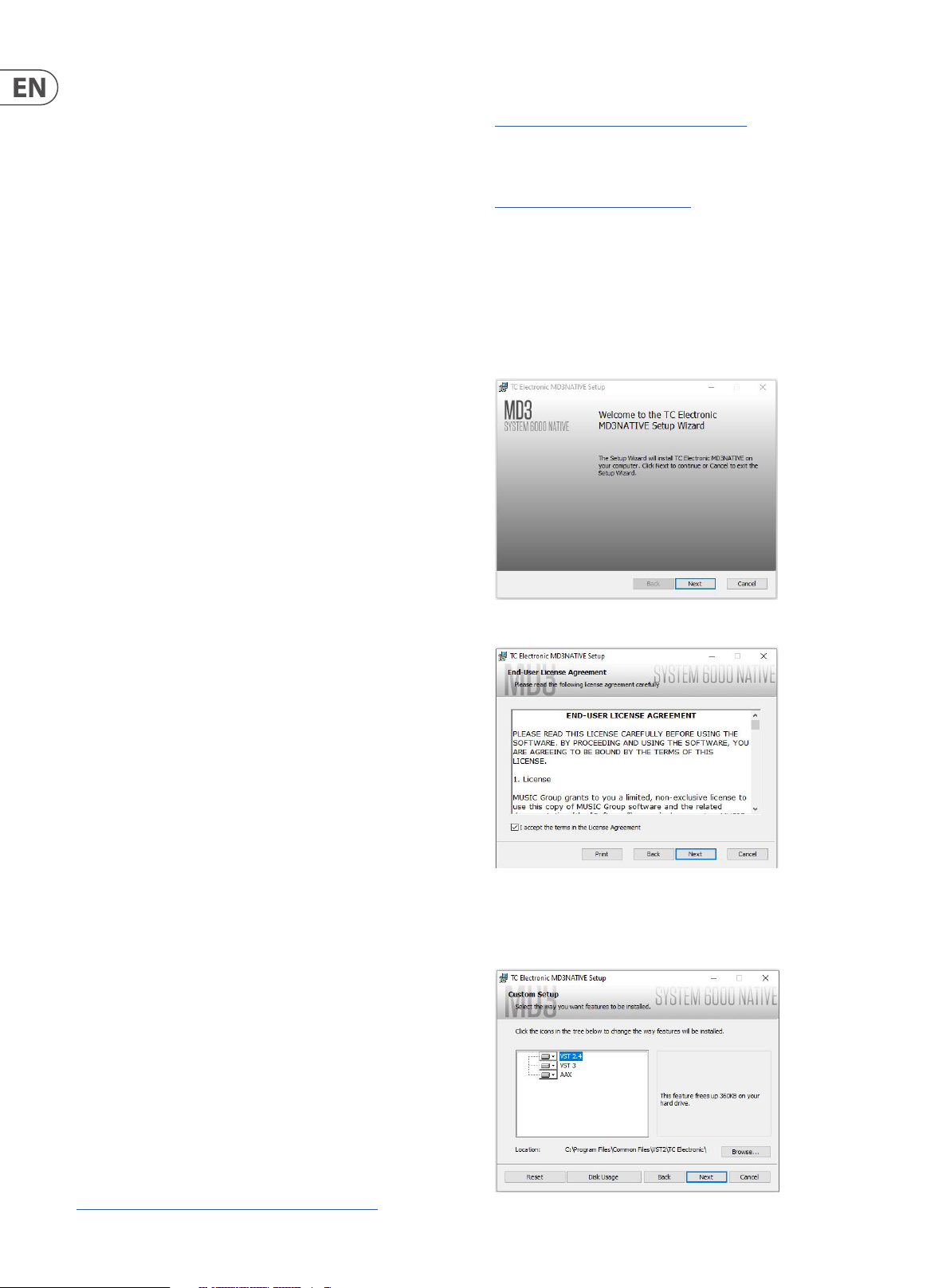
2.1 Installation on a PC
Double click the installer (.msi le). If you get a security warning, click ‘Run’.
The MD3 algorithm is a renement of our legendary MD2 dynamics algorithm
from the award-winning M5000 eects processor. The MD3 NATIVE plug-in
is tailor-made for music production in all forms. It uses a multi-band, highresolution oating-point structure, and features high-denition 4-band EQ,
3-band compressor/expander, soft clipping and a newly-designed transparent
peak/true-peak limiter.
The MD3 NATIVE parametric equalizer features a natural and well-dened bandwidth behavior at all gain and width settings, making it suitable for surgical
as well as broad spectral adjustments. MD3 features four bands, switchable
between Notch, Parametric, Shelving and Cut Filters.
MD3 NATIVE is known for its musical and dynamic behavior. The multi-band
section features full dynamics control of each of the 3 bands, with or without
automatic makeup gain, and with ability to choose compression of RMS, Peak
or anything in between. Further, it gives you the advantage of adjustable lookahead delay for gentle processing of transients, while the limiter lets you use its
own overshoot-proof micro-delay to prevent output samples above the either
peak or True-Peak dened threshold.
MD3 NATIVE operates in stereo and true mid/side processing with rare artifactfree split and recombination crossover lter banks and includes EQ unlinking.
MD3 NATIVE is the perfect tool for use for a wide variety of content material, ideal
for single sources, buses and master mixes.
TC Electronic wish you all the best, and hope that you will enjoy using the
MD3 NATIVE in your audio projects.
Accept the license agreement and click ‘Next’.
Select which VST and/or AAX components you want to install. Pro Tools uses AAX
and most other DAW programs use VST. The installer will oer a default location
to save the le, but you can choose another location by clicking
the ‘Browse’ button.
About this manual
Read this manual to learn how to install and use your TC Electronic MD3 NATIVE
plug-in. This manual is only available in PDF format from the TC Electronic
website. To get the most from this manual, please read it from start to nish, or
you may miss important information.
To download the most current version of this manual, visit the web page:
www.tcelectronic.com/Categories/c/Tcelectronic/Downloads
Click ‘Next ’ to begin the installation. When installation is complete, click ‘Finish’.
Page 5
5 MD3 NATIVE User Manual
Note: If your DAW fails to detect the newly installed plugin, this can often be
xed by adding the following paths to the Plug-in Manager (or similar) of the
DAW. The default paths on a PC are "C:\Program Files\Common Files\VST2" and
"C:\Program Files\Common Files\VST3" for VST2 and VST3, respectively.
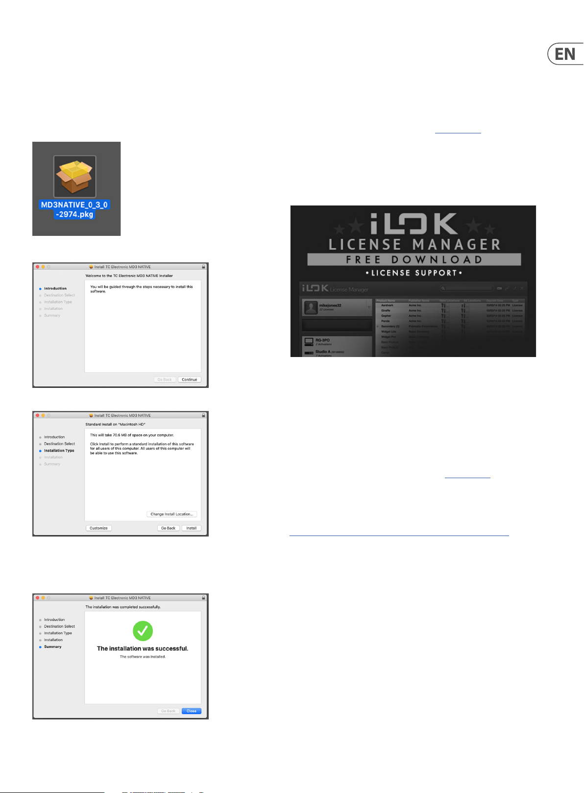
2.2 Installation on a Mac
Double click the installer (.pkg) le.
Proceed through the prompts to begin installation.
3. Activate the MD3 NATIVE iLok
license
3.1 Activation
Step 1: Install iLok
The rst step is to create an iLok user account at www.iLok.com and install the
PACE iLok License Manager on your computer if it’s your rst time using iLok.
Step 2: Activation
In the received mail when buying the MD3 NATIVE, you will nd your personal
Activation Code. To activate your software, please use the "Redeem an Activation
Code" feature in the PACE iLok License Manager.
Click ‘Continue.'
A default location will be selected for installation, or you can select another
folder manually. If you have administrator authorization in place, you will need to
enter your password before beginning installation.
3.2 Get a Free Demo License
Make use of this hassle-free oer to try out our plug-ins before you buy.
• 14-Day Trial Period
• Fully Functional
• No Feature Limitations
• No Physical iLok Key Needed
Step 1: Install iLok
The rst step is to create a free iLok user account at www.iLok.com and install the
PACE iLok License Manager on your computer if it is your rst time using iLok.
Step 2: Get your free trial license
Go to:
https://www.tcelectronic.com/brand/tcelectronic/free-trial-md3-native
and enter your iLok User ID.
Step 3: Activation
Activate your software in the PACE iLok License Manager.
Click 'Close' when done.
Page 6
6 MD3 NATIVE User Manual
4. Connection and Setup
4.1 Inserting the MD3 NATIVE plug-in in your
DAW project
Once you have downloaded the plug-in, you can now apply it to a channel in your
DAW to begin using the eect. This process may vary slightly depending on your
software, but generally should require these steps:
• Select a channel or bus in your DAW to which you would like to add the eec t.
Access the mixer page where you should see a section dedicated to eect slots.
• Open the menu where you can select from a list of eect types, which
probably includes many stock plug-ins that are included with the DAW.
There should be submenu to view general VST/AU/AAX options.
• The plug-in will likely be found in a dedicated TC Electronic folder. Select the
MD3 NATIVE and it will now be added to the signal chain.
Double click on the eect slot that contains MD3 NATIVE to view the plug-in UI.
4.2 Operating the MD3 NATIVE
After you have installed the plug-in, and activated the iLok license, you can begin
working with the plug-in on your tracks.
Adjustments to the eect are done using the plug-in user interface:
4.2.3 Bypass
Press the BYPASS button at the top to bypass or engage the MD3 NATIVE.
4.2.4 Automation
Please be aware that automation of cer tain parameters, can cause audible
artifacts.
In case you need to automate these parameters, you should take care that
changes only take place in parts where no audio is sent to the plug-in.
4.2.5 Parameter Overview
The MD3 NATIVE is a 3-band 2-Channel Dynamics processing algorithm. The
algorithm contains:
• • Stereo four band precision EQ (linked, left/right, or mid/side operation)
• • Stereo 3-band compression/expansion (stereo or mid/side operation)
• • The MD3 NATIVE will run at sample rates up to 192kHz
4.3 Signal ow through the algorithm:
NORMALIZER
GAIN
EXP/COMP
Most DAWs oer the ability to move or drag plug-ins from one track/bus to
another, and MD3 NATIVE supports this as well.
Most DAWs also feature an on/o switch for plug-ins, accessible inside the plug-in
window and/or the track itself.
Note that some DAWs don’t oer smooth on/o switching. Use the Global Bypass
button on the MD3 HD plug-in inter face for a smooth and latency-compensated
bypass.
4.2 .1 Insert vs Aux Eect
The MD3 NATIVE is intended for insertion directly into an eect slot on a single
channel, sub mix bus or master bus, which passes the entire signal through the
eect.
Be careful if using MD3 NATIVE on an auxiliary bus, as mixing the output of MD3
NATIVE with the original track sound will potentially create a phasing issue
depending on your DAW's ability to correc tly compensate for latency in plug-ins.
MS ENCODER
EQ
TRIM GAIN L/R
NORMALIZER
SOFT CLIPPER
MS DECODER
SOFT CLIPPER
LIMITER
OUT GAIN
4.2.2 Mono/Stereo Operation
The MD3 NATIVE can be used both as a mono instance on mono tracks and a
stereo instance on stereo tracks.
In the case of a mono out instance, the output signal is made by outputting the
left plug-in channel only. In this case, panning should not be used.
Page 7
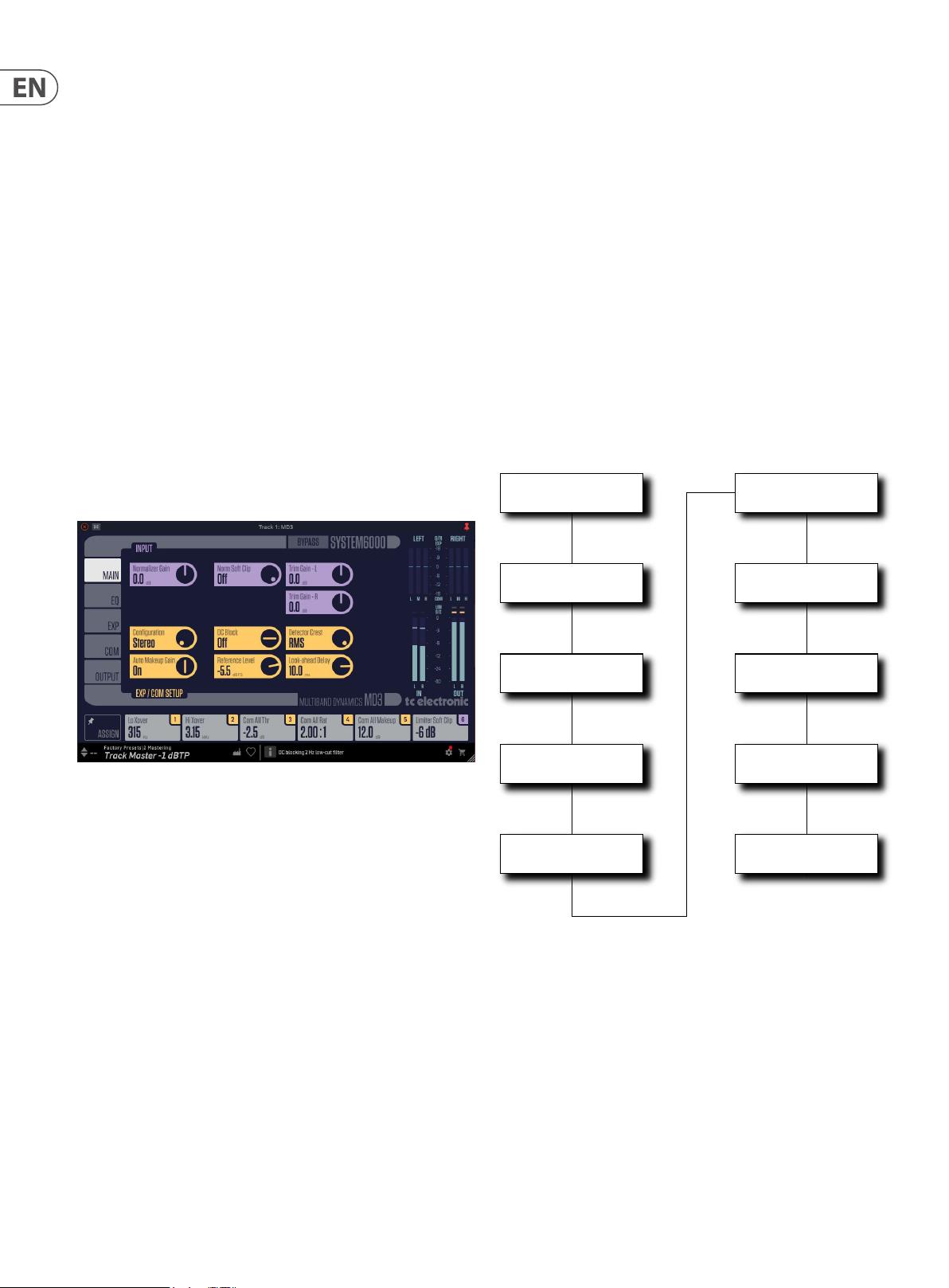
7 MD3 NATIVE User Manual
Global Bypass
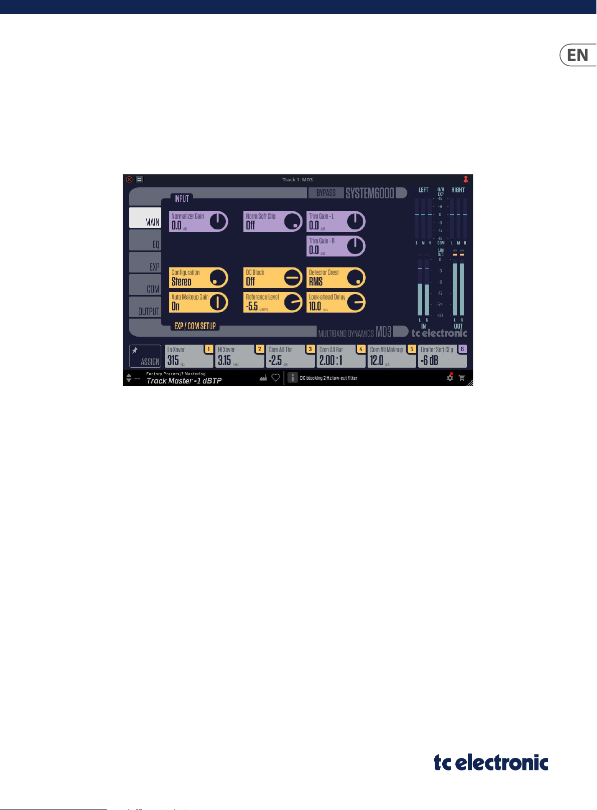
5. User Interface
5.1 Overview
There are ve tabs along the left edge of the interface, that bring up various
pages of controls. As a general note, the parameters, controls, and graphs are
color-coded as shown below:
The top part of the display:
• • Bypass: Press this to bypass or engage the MD3 NATIVE. This makes it
easy for you to listen and compare the overall eect of your awesome
work.
• • The EQ, expander, compressor, and limiter can be individually bypassed
using the ON button in each of their control pages
Tabs on the Left
• • Main: This brings up controls for the normalizer gain and soft clip, trim
gain left, right (purple), and controls (yellow) for initial setup of the
compressor and expander
• • EQ: The parametric equalizer, with controls for adjusting the frequency,
gain, EQ type, low and high cut, EQ bypass. The color coding is as
follows: Low (red), low mid (yellow), high mid (green), and high (blue)
• • Expander: Controls (purple) for expander threshold, range, ratio, attack,
and release
• • Compressor: Controls (yellow) for compressor threshold, range, ratio,
attack, and release, with compressor bypass
Meters
• • Gain reduction meters for compressor and expander: these show the
low, mid, and high for left/mid and right/side. The range (+/- 18 dB) can
be changed (+/- 9 dB) using the G/R Zoom button in the expander and
compressor pages
• • Input L/R meters (0 to -60 dB range with peak indication)
• • Output L/R meter (0 to -60 dB range with peak indication and limiter
action)
• • Use the input and output gain/trim controls in the MAIN and OUTPUT
pages to adjust the levels if required.
Near the Bottom
• • Assign Focus Fields: You can place your own favorite set of parameters in
the 6 focus elds. (See section 5.2.1 for more details)
• • The EQ, expander, and compressor (see the following pages), each
have a horizontal row of parameters just below their controls, such as
threshold, gain, etc. If you click on any of these, the parameters are
shown in this focus elds area for low, mid, high, and All. Click again to
return the focus elds to your assigned elds.
Along the Bottom Lef t
• • Preset number, preset name, factory or user, favorite, preset up/down
Along the Bottom Middle:
• • Tool Tips shows useful information about the current selection
• • Output: Limiter controls (purple) for gain, soft clip threshold, threshold,
ceiling, release, and mode, with limiter bypass. Output controls (yellow)
for output gain, balance, compare enable, and compare gain
Controls
• • Any of the circular controls can be adjusted either by dragging on the
dials or numeric value in the box, or by double-clicking and entering a
numeric value.
Main Tab
Normalizer
EQ Tab
Expander/Compressor Setup Controls
Expander
Compressor
Output
and Limiter
Bottom Right Corner:
• • Setup
• • Shopping cart
• • User Interface size adjustment
The controls and features are described in more detail in the following pages.
Input
Controls
Gain
Reduction
Meters
Left/Mid
Right/Side
Low Mid
High
Input
Meter
L/R
Output
Meter
L/R
Assign
Focus
Fields
Preset Up/Down Preset Name Preset Type
Preset Number Preset Favorite
Tool Tips Window
Setup and
Cart
Focus
Fields
1-6
Window Size
Adjustment
Page 8

8 MD3 NATIVE User Manual
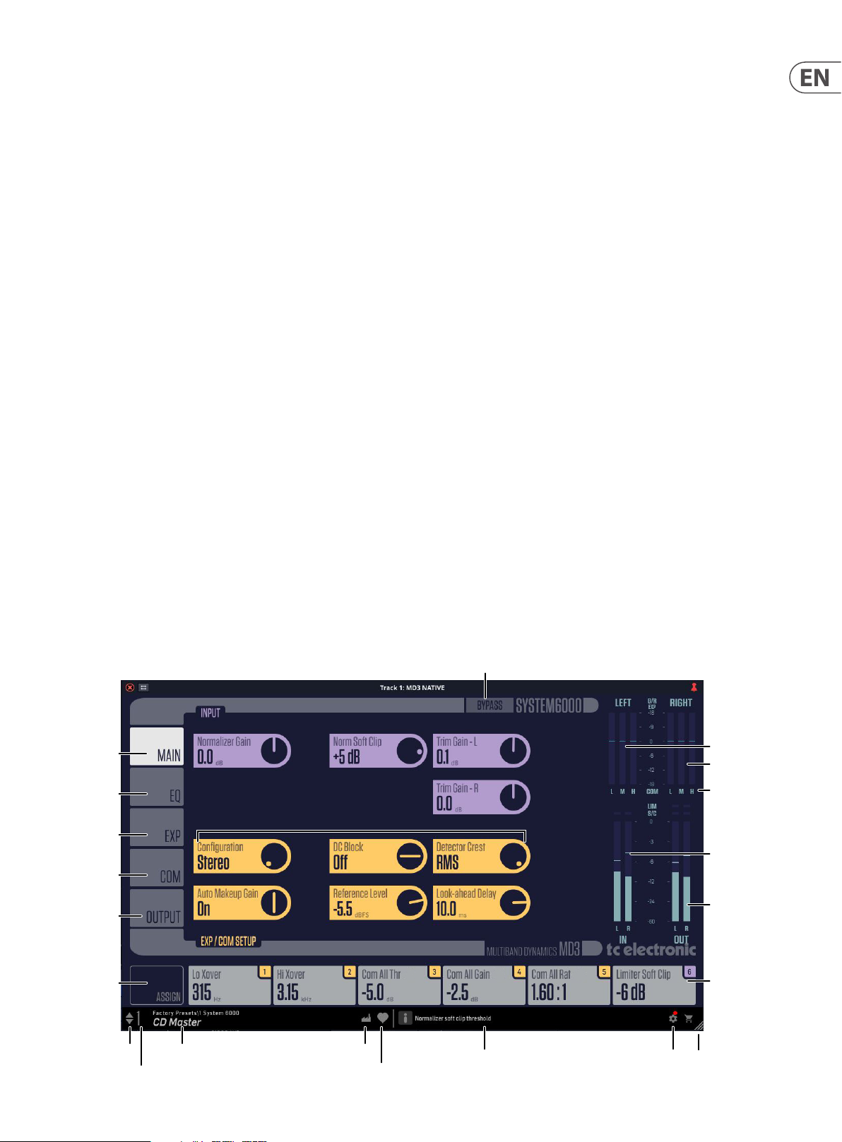
5.2 Main Page
Input (purple controls)
Normalizer Gain
Range: -18 to +18 dB in 0.1 dB steps
The Normalizer Gain is the rst gain stage in the plugin, used to adjust the overall
level of the input signal.
Norm Soft Clip
Range: +5 dB; O
The Soft clipper is placed between the Trim Gain and Exp/Comp section. By
enabling the Soft clipper you are able to reduce potential overshoots relative to
0dBFS.
Trim Gain (L/R or M/S)
Range: -12 to +12 dB in 0.1 dB steps
Trim the gain level for the two input channels to the Exp/Comp section.
When using the EQ section, the gain might have been increased or decreased. The
Trim Gains are used to optimize the gain before hitting the Expander/Compressor
section.
Expander/Compressor Setup (yellow controls)
Conguration
Options: Stereo, Mid/Side
Stereo
In Stereo Mode, the Expander/Compressor section of the algorithm uses by
default one common Sidechain for both Left and Right channels, and the EQ
section is linked. It can be unlinked.
Mid/Side (MS)
In this mode, the MS encoder is activated. The Expander/Compressor section of
the algorithm uses Sidechains as follows:
• • When DYN LINK is enabled there is only one Sidechain.
• • When DYN LINK is disabled there is a separate Sidechain for the Mid and
Side channel.
EQ can be linked or unlinked.
In Mid/Side mode, the left meter shows the Mid channel, and the right meter
shows the Side channel.
NOTE : When a mono signal is processed, only the left channel of the algorithm
is active
DC Block
Range: O, On
The DC block is a Low Cut lter at 2 Hz which is used to remove potential DC noise.
Detector Crest
Range: Peak, 6, 10, 12, 14, 16, 20, 24, RMS
Select the Sidechain level detection method of the compressor between RMS and
PEAK for all three bands. The dB steps between RMS and Peak are the number
of dBs needed for a peak-value to override the RMS measurement, and can be
perceived as a Threshold setting.
Example:
If the Crest parameter is set to 6dB, the Compressor will respond to RMS values
and to peaks 6dB higher than the current RMS value.
In Stereo mode, the gain reduction meters show the left and right channels.
Page 9

9 MD3 NATIVE User Manual
Auto Makeup Gain
Options: O, On
Switches the Automatic Make-up gain on or o for the Compressor bands. When
set to ON, the gain for each band is adjusted according to the Threshold and Ratio
settings. When set to OFF, no automatic gain adjustments are per formed.
Reference Level
Range: -24dBFS to 0dBFS in 0.5dB steps
This parameter sets the reference level in the algorithm.
The reference level is the level at which the Compressor Threshold parameters
will start operating when set to 0 dB.
The setting of the reference revel also aects the band gains applied using the
Auto Makeup feature. It can be benecial, for example, in order to keep “unity
gain,” to set the reference level close to the RMS level you are aiming for and
from then on use the Threshold parameter to set the amount of compression.
Look-ahead Delay
Range: 0 to 15ms
<2ms in 0.1ms steps
>2ms in 0.5 ms steps
Sets the look ahead Delay of the signal compared to the Sidechain signal. This
enables the compressor section to become more responsive to the incoming
signal, thereby performing a more precise compression.
5. 2.1 Focus Fields
Each of the six Focus Fields along the bottom can be assigned to any of the
available controls. These useful assignments remain visible when you switch to
dierent pages. For example, you can adjust the Compressor Ratio while you are
on the Expander page.
Click on the Pin Icon inside the ASSIGN but ton, and the Assigned Focus Fields will
remain when presets are changed. The numeric values within the Focus Fields
will change to the new preset values.
In the example below, Focus Field 1 has become Trim Gain Left by dragging the
control down and releasing it over the Focus Field 1 button. It will stay like this,
even when you move to the COM page or Expander page.
In the Expander, Compressor, and EQ pages, the Focus Fields will show other
parameters if any of the buttons are selected in the lower area of each page. For
example, here are the Focus Fields when GAIN has been selected in the row of
buttons below the EQ graph. To return to your assigned Focus Fields, deselect
GAIN by pressing it again.
Click on ASSIGN in the lower left, and you will notice that the control knobs will
become blank. (This is a good reminder that you are in ASSIGN mode.) Click and
drag any of the controls and drop it down onto the desired Focus Field 1 to 6.
You can also click the desired focus eld and then click the control to assign to it.
When nished assigning, select the ASSIGN button again.
Page 10

10 MD3 NATIVE User Manual
5.3 EQ Page
Introduction
This page features a 4-band parametric EQ, switchable between Notch and
Parametric lters. The Low and High bands can also be changed to Low/High Cut
or Low/High Shelving.
• • The needle-sharp notch lter has a range down to 0.02 octave
• • The parametric equalizer features a natural and well dened bandwidth
behavior at all gain and width set tings
• • The shelving lters have a variable slope, with options of 3, 6, 9, and
12 dB/oc t
• • The low-cut and high-cut lters are switchable bet ween 12 dB/oct
maximum at amplitude (Butterworth) or at group delay (Bessel)
types
Basic Operation
• • Press the colored but tons Low, Lo Mid, Hi Mid, and High at the top of the
graph, to activate/deactivate the EQ bands. Alternatively, double-click
on the colored handles in the graph
• • Click and drag left/right the colored handles in the graph to adjust the
frequency and drag them up/down to adjust the gain. Use CTRL+Drag
(or CMD+Drag on a Mac) to change the bandwidth
• • Press the ON button at the graph's top right, to bypass all bands
• • Below the graph, select Freq, Gain, Type or Lo/Hi to access all four
parameters on individual bands.
• • Press FREQ again, and the Focus Fields will return to their assigned elds
• • Select GAIN, and the Focus Fields show the gain in dB for each band.
Adjust the values in the Focus Fields as desired
• • Select LOW, and the frequency, gain, and type of the Low and Low Mid
bands are shown. Adjust the values in the Focus Fields as desired
• • Select HIGH, and the freqency, gain, and type of the High Mid and High
bands are shown. Adjust the values in the Focus Fields as desired
• • For example, if you press the FREQ button, the Focus Field below it
shows the frequency in Hz of all bands.
• • Click and drag the value in the Focus Field to adjust it, or double-click on
the value and manually enter a valid value
Page 11

11 MD3 NATIVE User Manual
Type /BW Selector
• • Select TYPE/BW and use the 4 Focus Fields to select lter types and vary
the parameters. Click and drag on the numeric value to scroll through
the types and their available values
• • Low and High lter options: Notch, Parametric, Shelve, and Cut
• • Low Mid and High Mid lters options: Parametric and Notch
• • Typical graphs of the dierent lter types are shown below:
Parametric Filter - Broad type
Notch Filter - Narrow Type
• • Bandwidth Range: 0.02 octave to 1 octave
• • Frequency Range: 20 Hz to 20 kHz
• • Gain Range 0 dB to -100 dB
Cut Filter - Bessel type
• • Bandwidth Range: 0.1 octave to 4 octave
• • Frequency Range: 20 Hz to 20 kHz
• • Gain Range -12 dB to +12 dB
Shelving Filter
• • Bandwidth Range 3, 6, 9, or 12 dB/octave
• • Frequency Range: 20 Hz to 20 kHz
• • Frequency Range: 20 Hz to 20 kHz
Cut Filter - Butterworth type
• • Frequency Range: 20 Hz to 20 kHz
• • Gain Range -12 dB to +12 dB
Page 12

12 MD3 NATIVE User Manual
5.4 Expander Page
Stereo or Mid/Side
The conguration control in the MAIN page allows you to select Stereo or MID/
SIDE for the expander and compressor setup (as well as the EQ, Trim Gains and
Normalizer Soft Clip).
Stereo Conguration
Mid/Side (MS) Conguration
Stereo Operation
If Stereo conguration is selected in the MAIN page, then the top section of the
Expander page shows STEREO, and the gain reduction meters are shown as LEFT
and RIGHT.
If Mid/Side conguration is selected in the MAIN page, then the top sec tion of the
Expander page shows STEREO initially, and the gain reduction meters are shown
as MID and SIDE. The DYN LINK selection allows the expander and compressor
controls to be linked between the stereo and mid/side.
Page 13

13 MD3 NATIVE User Manual
Turn o DYN LINK to allow separate expander control of the Mid and Side . The
Expander controls aect the Mid (initially) and Side instead of Stereo. Note that
an "M" appears in the controls as a reminder they are for the Mid.
Select SIDE, and the Expander controls will aect the Side instead of MID. An "S"
appears in the controls, to show they are for the Side.
If at any time you want the SIDE control set tings to be the same as the MID
settings, press the COPY button. (It will not copy from SIDE to MID).
X Over
The expander and compressor operate in three bands, using a low crossover and a
high crossover. The Gain Reduction meters show these three bands: L, M, and H.
Select X OVER along the bottom, and the Lo Xover and Hi Xover frequencies can
be viewed and adjusted by clicking and dragging in the rst 2 Focus Fields. Note
that any changes you make here will also aect the compressor, as it uses the
same crossovers.
The two crossover frequencies can be set to OFF (turned all the way down) in
order to run MD3 NATIVE as a two band or full band compressor/expander.
The example below shows THRESH. selected, and the separate threshold values
in the Focus Field displayed for each band, and the "Exp All" parameter in the 4th
Field.
The Mid Band value follows the Exp All value. If you vary Exp All then all three
bands will change, but maintaining the same relative levels to each other.
Note that an "M" appears in the controls if they are for the Mid.
Note that an "S" appears in the controls if they are for the Side.
Threshold
Range: -50dB to 0dB (in 0.5dB steps)
When the signal drops below the set Threshold, the Expander is activated.
Range
Range: -40dB to 0dB (in 0.5dB steps)
The Range parameter sets the Max attenuation relative to the Ref level setting
(see Main page). Example: With a Ref Level setting of -6 dB and Range set to -10
the max attenuation can be -16dB.
Ratio
Controls
Use the rotary control knobs to adjust the overall Threshold, Range, Ratio, Attack
and Release. The knob values correspond to the EXP ALL value shown in the 4th
Focus Field mentioned below.
If you select Threshold, Range, Ratio, Attack or Release buttons, then the Focus
Fields will show the Exp Lo, Exp Mid, Exp Hi, and Exp All values for the selected
parameter. This allows you to adjust the expander parameters for the low, mid,
and high bands. Adjusting the Exp All value adjusts the value of all three bands.
However the Exp Mid value only adjusts itself and the Exp All value.
Range: O to Innity
The Ratio of the Gain Reduction.
Example: If the signal drops 1 dB below the Threshold with a Ratio set to 1:3 the
actual attenuation will be 3 dB.
Attack
Range: 0.3 to 100 ms (Exponential)
The Attack time is the time the Expander uses to release its gain reduction when
the Input signal rises above the set Threshold.
Release
Range: 20ms to 7 sec. (Exponential)
The Release time is the time the Expander uses to achieve the attenuation
specied by the Ratio parameter when the signal drops below the set Threshold
point.
G/R Meter Zoom
Press to zoom in on the range of the Gain Reduction meters, from +/- 18 dB to
+/- 9 dB
Page 14

14 MD3 NATIVE User Manual
5.5 Compressor Page
Stereo or Mid/Side
The conguration control in the MAIN page allows you to select Stereo or MID/
SIDE for the expander and compressor setup (as well as the EQ, Trim Gains and
Normalizer Soft Clip).
Stereo Conguration
Mid/Side (MS) Conguration
Stereo Operation
If Stereo conguration is selected in the MAIN page, then the top section of the
Compressor page shows STEREO, and the gain reduction meters are shown as
LEFT and RIGHT.
If Mid/Side conguration is selected in the MAIN page, then the top sec tion of
the Compressor page shows STEREO initially, and the gain reduction meters
are shown as MID and SIDE. The DYN LINK selection allows the expander and
compressor controls to be linked between the stereo and mid/side.
Page 15

15 MD3 NATIVE User Manual
Turn o DYN LINK to allow separate expander and compressor control of the Mid
and Side. For MID, an "M" appears in each of the controls.
Select SIDE, and the Compressor controls will aect the Side instead of MID. An
"S" appears in each of the controls.
If at any time you want the SIDE control set tings to be the same as the MID
settings, press the COPY button. (It will not copy from SIDE to MID).
X Over
The expander and compressors operate in three bands, using a low crossover and
a high crossover. The Gain Reduction meters show these three bands: L, M, and H.
Select X OVER and the Lo Xover and Hi Xover frequencies can be viewed and
adjusted in the rst 2 Focus Fields. Note that any changes you make here will also
aect the expander, as it uses the same crossover.
The two crossover frequencies can be set to OFF (turn all the way down) in order
to run MD3 NATIVE as a two band or full band compressor/expander.
The Mid Band value follows the Com All value, and is the same value as the rotary
knob. If you vary Com All then all three bands will change, but keeping in the
same relative levels from each other.
Note that an "M" appears in the controls if they are for the Mid.
Note that an "S" appears in the controls if they are for the Side.
Threshold
Range: -25dB to 20dB (in 0.5dB steps)
Relative to the Ref.Level setting (Main page).
When the Input signal exceeds the Threshold value, the Compressor star ts to
reduce the dynamic content of the signal according to the set Ratio.
Ratio
Range: O to Innity
Controls
Use the rotary Compressor control knobs to adjust the overall Threshold, Range,
Ratio, Attack and Release. The knob values correspond to the Comp All values you
will see in the 4th Focus Field shown below.
If you select from the row of Threshold, Range, Ratio, Attack and Release buttons,
then the Focus Fields will show the Com Lo, Com Mid, Com Hi and Com All values
for the selected parameter. This allows you to adjust the compressor parameters
for the low, mid, and high bands. Adjusting the Com All value in the 4th Focus
Feild adjusts the value of all three bands. However, the Com Mid value only
adjusts itself and the Com All value.
The example below shows RATIO selected, showing the separate ratio values in
the Focus Fields for each band, and the "Com All" parameter in the 4th Field. In
this example, the Lo band ratio is 3.20:1 and the Mid and Hi are 2.00:1.
Species the Ratio of the performed compression.
Example: With a Ratio setting of 2:1 the compressor will reduce every 2dB above
the Threshold point to only 1dB.
Makeup Gain
Range: -12dB to 12dB in 0.5dB steps.
Manual Makeup-gain for each compression band.
Where the Auto Gain control in the Main page compensates for the total gain
reduction caused by the Compressor, the Gain controls in the Compressor page
are used as additional gain controls on the individual bands.
Attack
Range: 0.3 to 100ms
The Attack time is the time the Compressor uses to reach the gain reduction
specied by the Ratio parameter.
Example: If the Input signal increases by 4dB above the set Threshold, with a
Ratio set to 2:1 and the Attack time is set to 20ms, then the Compressor will use
20ms to reach a Gain reduction of 2dB.
Release
Range: 20ms to 7s
The fallback time. This is the time it takes for the Compressor to release the
attenuation of the signal.
G/R Meter Zoom
Press to zoom in on the range of the Gain Reduction meters, from +/- 18 dB to
+/- 9 dB
Page 16

16 MD3 NATIVE User Manual
5.6 Output Page
The Limiter
The limiter cannot prevent destruction of dynamic range from happening at
earlier stages in the production process, but it can get rid of the signals we
know are going to get distor ted in consumer CD players, radio processors or data
reduction codecs.
The limiter operates with extended precision in both level and time. Doubleprecision calculations are always used.
The Limiter employs adaptive time constants to combat distortion at low
frequencies, while maintaining quick adoption to occasional peaks.
Limiter Gain
Range: -12 dB to +12 dB in 0.1 dB steps
The Limiter Gain is used to control the output loudness (sits between the
compressor and the limiter soft clipper)
Limiter Soft Clip
Range: -6 dB to 0 dB in 1 dB steps; +3 dB; o.
Soft clipper threshold (sits after the Limiter Gain).
The softclip threshold is relative to 0 dBFS - not to the Ref Level.
Limiter Threshold
Threshold is relative to 0 dBFS - not to the Ref Level.
Range: -12 to 0 dB in 0.1 dB increments, OFF
Limiter Release
Range: 10 ms to 1 second, in 10 ms steps
Release time for the Limiter.
If quick recovery and loudness is important, move the Release setting in the
Fast direction. Processing of very sensitive material might sound better with the
Release settings in the Slow direction.
Limiter Ceiling
Range: 0 to -2 dB in 0.1 dB steps.
This ne-tuning parameter is used to set the Ceiling for the Limiter.
Limiter Mode
Options: Sample or True Peak
We recommend using the limiter in True Peak mode, for hyper precision in limiter
timing. True Peak is required from standards when delivering for modern music
streaming services, web and TV.
However, if you wish to just limit the signal based on sample by sample values
like a normal digital limiter, then select Sample mode.
ON
Press to engage/bypass the Limiter section.
Page 17

17 MD3 NATIVE User Manual
Output Gain
Range: O to 0dB (<-40dB: in 3dB steps, >-40 in 0.5dB steps)
Output level adjustment for both channels.
Output Balance
Range: 6 dB Left to 6 dB Right in 0.1 dB steps
Changes the Output balance between the Left and Right channel.
Compare Enable
Click to activate the compare function, and tactivate these controls. Due to the
dierence in level, "in-circuit" and "out-of-circuit" comparisons are often dicult
to make using the BYPASS key. Use the Compare Gain parameter to compensate.
Compare Gain
Range: -20 to 0 dB in 0.1 dB steps
Processing with MD3 NATIVE will most often also mean raising the level of the
signal.
To make a realistic comparison of processed and unprocessed signal, it is
important to compare at equal levels. Use the Compare level to set a level for the
processed signal.
Page 18

18 MD3 NATIVE User Manual
6. Dynamics Processing In-Depth
After the Normalizer Gain, the signal is gently split into 3 overlapping bands the low, mid, and high frequencies. It will then compress each band somewhat
independently. Thereby, for example, a powerful kick-drum will not modulate
the processing of the lead vocals. After compressing/expanding, the 3 bands are
combined again.
6.1 Compressor
The very basis of compression can be reduced to "controlling the dynamic
content" of an audio signal. This basically means turning down the loudest parts
of the source material and raising the volume of the parts with low level content.
But how this is done, and how this is applied in audio production, is slightly more
elaborate.
Keep an eye on the illustration below and let us look at the basic compression
parameters:
Examples of Compressor Threshold, Ratio, Curve, and
Factor
Let us look into setting the Threshold and Ratio. In many cases, you would use a
low threshold, in combination with a small ratio and vice-versa. Let us choose a
low threshold of -23 dB and a small compression ratio of 2.5:1.
We have now set the compressor – but with identical settings for all three
bands. With identical settings, we are not taking full advantage of the multiband
capabilities.
This is where the individual band controls come in. Click on the Threshold control
and the Focus Fields will change to show the threshold values for Low, Mid, and
High, and All. The controls allow you to create dierent settings for each of the
three bands. Click the control again to return to the Assigned Focus Fields.
Threshold
The Threshold parameter sets the limit where the compressor kicks-in/
releases its grip of the signal. As soon as the level is above the set threshold the
compressor is active. When below - it is not.
Ratio
The Ratio sets the amount of gain reduction applied when the signal exceeds the
threshold. In the illustration above, the Ratio is the steepness of the curve after
the compressor threshold.
Attack
The Attack time is the time it takes for the compressor to reach the compression
amount specied by the set ratio.
Release
The Release time is the time it takes for the compressor to release the signal
after the input signal is below the threshold point again. How each of these
parameters are set is very important, and only the correct combination gives the
desired result.
Examples of Attack, Release and Crossover frequencies
Let us look into how to set the Attack and Release Times.
We start with small values for both parameters. If the attack time is too short,
we may remove some nice transients or “kick” from the material. This may not
be what we want, so we could try a greater value instead. Heavy peaks can be
smoothed using the limiter section.
If the release-time is too fast, it may result in a “pumping” eect, because the
compressor returns to the uncompressed signal immediately whenever the signal
falls below the compressor’s threshold setting. If so, we could increase the value
of the release time until we are satised with the result.
You could start with an Attack time of 1ms and a Release time of 0.2 s.
If you do not get the desired result, you could also try some dierent crossover
frequencies. Keep in mind that you have three independent bands – why should
a bass drum signal aect the mid and high bands when its peak is in the low end?
You could start out by using 125 Hz and 2.5 kHz if applied on drums, or 315 Hz and
3.15 kHz if applied on a full range mix.
Note: Sometimes it is easier to adjust the Attack and Release times and the
Crossover frequencies by using extreme values for Threshold and Ratio during
setup. This will make the eec t of your settings much easier to hear.
Page 19

19 MD3 NATIVE User Manual
6.2 Limiter
The Limiter is actually yet another compressor. It uses a very fast attack time and
has a ratio of 1 to innity. But why is the Limiter necessary?
For the compressor to be used as a musical tool, the set attack times are relatively
long (from 1 to 100 ms). This gives the disadvantage that certain peaks can pass.
Therefore a limiter with an attack time of as little as 0.1 ms and a ratio of 1 to
innity prevents nearly all overshoots.
You may want to use the Limiter carefully, as a limiter is always a somewhat
“drastic” tool to apply to your audio. If on a full mix, just a couple of dB should be
enough to limit strong peaks. If on a channel, feel free to sculpt your sound but
beware that the more compressed and limited it is, then the less “life” and more
“ear-fatiguing” it will most likely sound.
As an example, you could chose a threshold of -6 dB. The release time could be
set to a value that could avoid unwanted pumping (0.3 s).
6.3 Gate/Expander
By compressing the signal, we made it sound louder due to the auto make-up
gain in the compressor (set in the Main page). An unwanted side eect is that
the ground oor level is also brought up. The noise will be most evident in the
pauses.
Noise, whether it is hiss, hum or just background noise, is always a parameter to
evaluate and deal with. Initially, noise must of course be reduced to a minimum
from the source, but with a Gate/expander it is also possible to reduce the noise
on channels when no signicant signal is present.
A Gate - or downward expander, - is used to attenuate the signal when the signal
is below a certain threshold. When talking about attack and release times in
reference to a noise gate: - the attack time is the time is takes for the gate to
"open" when the signal rises above the threshold and the release time is the time
it takes for the gate to reach the specied attenuation.
Use the Expander carefully. The modulated noise, due to the Expander shifting
between opening up and reducing the noise, of the ground oor level is much
more audible than a higher ground oor level without such modulation.
The Expander’s threshold must be lower than the compressor’s threshold. If you
raise it too much, you might cut into low parts of the signal, such as reverb tails.
The Expander’s Ratio parameter determines the width of the level range.
Note: The Attack time is a critical parameter for an expander. A short Attack time
will be suitable for transient content like drums, but may create audible artefacts
if applied to less-transient content like drone synth sounds.
Note: A rather seamless way to reduce noise by using a gate or expander, is to
turn down the treble, then the mids and then the bass.
6.4 Modern Mastering, Loudness and TruePeaks
The MD3 NATIVE is a multi-band dynamics-multi-tool, highly suitable for the
mastering process, with many ways to make your mix sound better, but if not
used wisely, there are many ways of making it sound worse!
There is a risk of becoming speed-blind in the tuning process, and at rst prefer
an over-compressed and loud-sounding track. This is a situation that can be
avoided by:
The Expander is one possible cure for this, as it will reduce audible noise when
applied to vocal tracks, for example.
• • Knowing your music genre deeply
• • Using relevant reference tracks for comparison
• • Ensuring calibrated monitoring levels
• • Using an optimized monitoring environment
The resulting Loudness and Dynamic Compression are two of the most important
properties of a track, adjusted nally in mastering. These two properties can be
regarded as counterparts to each other. In other words, it is important to:
• • Decide how loud your tracks should be
• • Design the dynamic prole of your music
Due to the xed 0 dBFS ceiling in digital audio, louder tracks have less dynamics,
and “weaker” tracks will potentially have more dynamics.
We recommend that you do not hyper-compress and limit your tracks to the
extreme in the mastering process, in order to achieve a loud track. If you overdo
it, it will potentially reduce the audio quality of your work. And often, there
is even a penalty in playback stages so your loud track may end up sounding
weaker, rather than louder.
6.4.1 Loudness
The Loudness approach to music mastering is based upon similar methods
introduced more than a decade ago by the industry producing audio for TV.
Loudness measures how loud we actually hear audio, which is dierent from
“level” PPM meters that look at transients only. The Loudness method includes
K-ltering that emulates human hearing, where bass aects the perceived
loudness level less, and where frequencies from approximately 2 kHz and up
aect the perceived loudness level more.
Page 20

20 MD3 NATIVE User Manual
Loudness is a modern, but still well-rehearsed reference method, which is
standardized in BS-1770, and many music streaming services refer to this
standard, or similar proprietary methods.
Loudness is measured on the LUFS metering scale. LUFS stands for "Loudness
Units Full Scale." The scale does not measure sound as a dB meter or a VU meter
would. Rather, it accounts for how the human ear (and brain) perceives the
loudness of a track. That is also why there is only one loudness value or level,
instead of one per channel.
Loudness examples: Some Streaming Services will aim for -16 LUFS loudness
when they play back music tracks with “Sound Check” enabled. The AES
community recommend streaming music between -20 and -16 LUFS. Often
you will see songs that measure -14, -12, -10 or even -8 LUFS and it will vary for
example by music genre.
6.4.2 True Peak
Often, there can be small peaks of sound in-between digital samples,
intersample peaks, that go undetected in most digital tools. Where traditional
peak meters and conventional peak limiters fail to read these true peaks of
sound, a True Peak meter will provide the mastering engineer with the actual
reading.
Without a True-Peak Limiter, a mastered track could go into digital clipping when
converted to a lossy format like MP3 or AAC or when being Digital-to-Analog
converted in normal playback systems. This can happen, even if no distortion is
heard when monitoring the nal master.
that aligns the loudness of the songs in the library. And if that happens, your very
loud song may well end up sounding much less impressive than the competition!
6.4.4 Compress-O-Meter - Master Analyser
TC Electronic has launched a free on-line service at the following address:
https://nalizer.com/analyzer
This analyzer can help you investigate and decide the suitable loudness level
and amount of dynamics processing for your music, when you compare it to your
preferred reference tracks, or pre-analyzed giant hits through the history.
A central part of this service is the Compress-O-Meter:
Although it doesn't have a True-Peak meter, the MD3 Limiter can be set to TruePeak mode, which ensures that there are no intersample peaks above the level
that the limiter threshold is set to. Set the parameter "Limiter Mode" to True Peak
to activate this. Be aware that further processing af ter the MD3 might introduce
intersample peaks again.
6.4.3 Beware of The Loudness Wars
An important note on loudness, is that there has been a trend in mastering
toward making songs appear louder and louder. Since you can never exceed
the 0dBFS digital ceiling, applying a brickwall Limiter at the nal stage, the
result often has been to apply very aggressive settings on dynamics tools such
as multiband compressors, so-called ‘loudness optimizers’, as well as the nal
Brickwall Limiter itself. This phenomenon has been referred to as ‘The Loudness
Wa rs ’.
This escalated because we naturally perceive a louder version of a song to be
better than a sof ter version, when you compare them directly. Another cause is
that record industry people would compare an ‘airplay’ version of one track to a
newly mastered CD track, where the former tended to sound louder and fatter
due to FM broadcast processing – leading to a request to make the master louder,
with more cowbell. Well, the ‘wars’ may have peaked, but it is still something
that you should be aware of and pay attention to. And while we say that they
may have peaked, they are not completely over…
Further, if you apply extreme amounts of compression, distor tion occurs, which
may lead to listening fatigue for you as well as your audience. Of course, the
amount of compression that you can use in order to t a certain music genre can
vary, but just stay aware of how it aects your music, and act accordingly.
It is also very important that you always listen to your own mastering project and
your reference library at the same loudness level when you compare them. There
is no doubt that while a heavily compressed song – dynamically speaking – may
sound more impactful at rst, you will sacrice detail and nuance.
The X-axis is the amount of Dynamic Compression. It is unit-less, so you should
not add “dB”, “ratio”, or similar, when thinking about it.
The Dynamic Compression is based on the track’s Peak-to-Loudness (PLR) value
and a measurement of the micro-dynamics of the track.
• • Very dynamic music with lots of transients and loud and soft passages,
will have a low Dynamic Compression value, to the left in the CompressO-Meter.
• • Very dense music with little transients, will have a high Dynamic
Compression value and show up to the right.
The Y-axis is the full track Loudness value, shown in LUFS (Loudness Units Full
Scale).
6.4.5 Additional tools
We recommend using the Icon Series BRICKWALL HD for adding detailed True
Peak limiting and loudness awareness to your chain, which will ensure a solid
master audio le that will comply with any play back system or streaming
service.
Finally and as mentioned above, keep in mind that the current trend in music
streaming is a target loudness of approximately -16 LUFS, so if you deliver a
signicantly louder song, it will get turned down automatically if the listener
chooses to apply the ‘normalization’ feature such as ‘SoundCheck’ or ‘Same Level’
Page 21

21 MD3 NATIVE User Manual
7. Presets
The MD3 NATIVE oers a collection of factory presets, as well as the option to
create and save your own custom settings as user presets and favourites.
Note that most DAWs have a built-in preset function that appears on every plugin, which is often found at the top of the plug-in window.
It is not recommended to use this as your primary method of saving presets, as it
has limited functionality and does not allow the saved presets to be transferred
easily to other DAWs. Instead, we suggest using the Preset section at the bottom
corner of the user interface window:
A single click on this PRESET window brings up a menu with several presetrelated options. You can recall a fac tory or user preset from the libraries, save the
current preset, or create a new user preset with the 'Save as' option.
7. 2 User Presets
If you make an alteration to any of the parameters in the current preset, the
preset name changes to italics as a reminder that something has changed from
the original factory preset.
To save this new setting as a User preset, click in the PRESET window, then select
the Save As option. Save it with an appropriate name.
To discard the changes without saving, simply navigate away from that preset.
The presets menu is divided into Factory Presets and User Presets.
7.1 Factory Presets
Factory presets are built into the plug-in and cannot be overwritten, so if a
factory preset is modied and you want to keep the changes, you need to save it
as a User preset. User presets can be edited and organized as you like.
When recalling a Factory preset or saved User preset, the name will appear in
plain text as shown below.
It will have a number to the left of the title, if it has been assigned as a favourite
(see later), otherwise it will show "--" next to it. Do not be alarmed.
The altered preset will be saved as a user preset, with your new name for it, and
its name will appear in the presets window.
If you modify a saved user preset, you have the option to "Save" (overwriting over
the existing user preset) or "Save As" (save as a new user preset).
If you modify a factory preset, then only "Save As" is available (to save as a new
user preset). Factory presets cannot be overwritten.
User presets are not given a number unless you assign them as favourites. (See
Favourite Presets below.)
Page 22

22 MD3 NATIVE User Manual
7. 3 Favorite Presets
Creating your own presets will make them accessible from the Preset menu,
but they will only appear in the list of 100 favorite presets in the plug-in if you set
them as a favorite. This is done by assigning a favorite slot number to the preset
using the Favorite menu.
Click the FAVORITE (heart-shaped) button at the right edge of the preset window,
then select one of the 10 banks. Assign one of your custom presets to a favorite
slot, then save the preset.
7.3.1 Browse Favorites Only
The 'Browse Favorites Only' option in the preset menu allows the UP/DOWN
arrows in the bottom bar of the plug-in. Otherwise, scrolling goes through all
presets.
7.4 Make Current Preset Default
Selecting 'Make current preset default' will cause this preset to appear every time
a new instance of the plug-in is created.
7. 5 Reveal User Preset Folder in Explorer
To change the name of a preset, select 'Reveal User Preset Folder in Explorer'
and modify the le name. This will open a Finder (Mac) or Explorer (PC) window
where the user presets are stored. You can rename as well as delete, copy and
paste presets. This allows you to share presets with other users online, simply
pasting the new ones in this folder.
When a preset is assigned a favorite slot number:
• • The preset is part of the 100 presets that can be recalled
• • The favorite number will be locked so that two presets cannot be
assigned to the same favorite slot number. This is shown in the Favorite
menu by graying-out the number in question
• • The favorite number will be displayed in brackets when you browse the
presets menu
You can remove the favorite assignment by selecting the “Remove Assignment”
feature in the Favorite menu, then saving the preset.
Page 23

23 MD3 NATIVE User Manual
8. Software Updates
New versions of the sof tware may be released to add new features and improve
performance. Updates can be detected from the plug-in directly and can be
installed after download from the website. See Chapter 2 for plug-in installation.
If the ’Automatically check for updates’ option is checked inside the update
menu, the red dot will appear on the settings icon when a new plug-in
is available.
Click the gear icon and select “Check for Updates” to perform a scan.
9. Specications
Sound
Processing 3 Band expansion/compression/
limiting, softclip
Sample rates 44.1, 48, 88.2, 96, 176.4, 192 kHz
Software Support
Operating systems Mac OS X 10.13 High Sierra or above,
Windows 7 or above
Plugin formats AAX-native, Audio Units, VST2.4,
VST3. 64 bit
Page 24

 Loading...