

Page 1

CONFIGURATION
This section contains text modules concerning configuring either software or hardware
applications. When software is released or a new module card is purchased, refer to this
section in order to install it properly. The section contains the following text modules:
M5000 APPLICATIONS
SOFTWARE INSTALLATION
HARDWARE INSTALLATION
OPTION INSTALLATION
HIGH MEMORY OPTION
SIMM PACK INSTALLATION
CONFIG. M5000
M5CONFIG
Rev 1.3 Page 1
Page 2
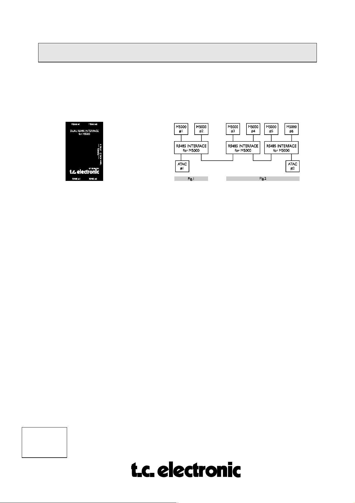
MULTIPLE ATAC/M5000/M5000X SETUP
The ATAC-remote system is capable of controlling multiple M5000/X main frames. The link
that enables the data communication is the
also referred to as the
MULTAC
, and the proprietary
INTERFACE and a connection example is illustrated below:
With one RS485 INTERFACE (MULTAC) you are able to connect one or two M5000/X
frames. The M5000/X´s are to be connected to the M5000/X #1 and #2 plugs (Fig.1).
The RS485 plugs each connect to either one ATAC or is used to loop on to the next
MULTAC box (Fig.2). Additionally, you are able to connect two ATACs using both RS485
sockets.
TC DUAL RS485 INTERFACE for M5000/X
TC Network Protocol
. The RS485
,
When connecting two ATACs, in a multiple M5000/X/ATAC setup, you gain the advantage
that two users can communicate simultaneously. Please note that two users cannot access the
same mainframe at once.
The MULTAC also has DC plug connections for the ATAC power supplies.
Cables:
You may substitute the cable, connecting the ATAC to the MULTAC, with a “MIDI Plus”
cables (5 pins with shield).
A 7 pin cable with shield must be used when connecting the M5000/X with the MULTAC.
Note: To ensure a safe data transferal, please follow the cable length requirements stated
below:
1.
When only ONE M5000X is connected use max. 10m/33ft of remote cable.
2.
In a MULTIPLE M5000/X/ATAC setup, lengths of the cables connecting the ATAC to the
MULTAC can be extended to 100m/328ft. Maximum lenghts may not exceed 100
meters/328 ft.
CONFIG. M5000
M5CONFIG
Rev 1.2 Page 2
Page 3

SOFTWARE INSTALLATION M5000
Here is the procedure for updating the application software in the M5000. You need to get to
the special M5000 Setup Utility menu to accomplish this.
1. Turn the power off the M5000.
2. Press the BYPASS button (22) while switching power on again. Hold it for a
few seconds. The
3. With the PROGRAM DIAL (17) you choose the appropriate option:
M5000 Setup Utility Menu
will appear.
LOAD DISK/CARD
When DO is pressed the directory of the inserted
floppy disk or memory card will appear. Scroll
through the files with PROGRAM DIAL. Select the
file by pressing DO and confirm the choice by
pressing DO again. Software from floppy disk or
memory card will be loaded. The UNDO button works
as a cancel button and returns you to the Setup Menu.
SAVE DISK/CARD
Saves the application software to a formatted floppy
disk or memory card. By pressing DO you enter the
name menu which enables you to give the application
software a file name on the disk/card. On the top line
a file name is displayed with a cursor under the first
character - ready for editing.
SOFT DIAL A: CURSOR Moves the cursor forward or backwards through
the name. The name can have a maximum of 8
characters.
SOFT DIAL B: LETTERS Selects a letter from A to z and inserts it in the
name over the cursor.
SOFT DIAL C: FIGURES As letters but numerical from 0 to 9.
SOFT DIAL D: SYMBOLS Inserts symbols instead of characters, e.g. blank
or space is a symbol found here.
(Press DO to confirm file name.)
LOAD MIDI
Enables you to receive software updates from another
M5000 (See SAVE MIDI) or you can use TC's
M5DUMP software package which enables you to
dump software to the M5000 via an IBMtm compatible
PC with a MIDI interface installed. This package is
available from TC's bulletin board free of charge for
M5000 USER CLUB members and instructions are
implemented with the program.
CONFIG. M5000
M5CONFIG
Rev 1.3 Page 3
Page 4

SAVE MIDI
Enables you to dump the software from one M5000 to
another. Connect this (master) M5000's MIDI out to
another (slave) M5000's MIDI in. Select 'SAVE MIDI'
in order to transmit. The Slave M5000 must be set at
'LOAD MIDI'. Press DO at the master first and then
press DO at the slave. An ERROR detector will
inform you if any errors arises during MIDI dump. If
any errors are detected it is recommended that you
repeat the procedure. It is of course also possible to
save the application software over MIDI to an IBM
tm
compatible PC if you haven't a floppy disk instal-led.
SERIAL #
FORMAT CARD
FORMAT DISK
Read Only parameter. Shows the topical serial number
of the M5000 and the BIOS version no. If the FLASH
EPROM is a 2 Megabit size it is also shown here. If
not - it is a 1 Megabit.
Formats a never used memory card or erases the
existing files. Insert the unformatted card or a card
you want to erase that supports the JEIDA PCMCIA
standard. A 64 Kb memory card will be able to hold
over 2000 programs. Press DO and the display will
tell you that all data will be erased on the card.
Confirm by pressing DO or abort by pressing UNDO.
Formats a floppy disk with the IBMtm compatible
format. After format there will be 1.44 MB available
on disk. This means that if the application software is
stored on disk there are room for over 50,000
programs. Press DO and the display will tell you that
all data will be erased on the floppy disk. Confirm by
pressing DO or abort by pressing UNDO.
CONFIG. M5000
M5CONFIG
Rev 1.2 Page 4
Page 5

HARDWARE INSTALLATION M5000
When the time comes when you want to upgrade your M5000 with additional modules in
order to run more than one effect simultaneously, the procedure is as follows:
1. Switch the machine OFF and disconnect the main power cord.
2. Remove the DUM-1 option plate(s) or module by loosening the 2 screws.
As the M5000 modules are sensitive to static electricity, certain precautions must be taken to
protect them from damage during storage and handling.
STORAGE
Non-mounted modules should always be stored in anti-static shielding bags.
GENERAL HANDLING
When inserting or removing any modules, avoid touching the circuit board by handling only
the rear panel of the module. Modules should always be placed in either an M5000 or in a
shielding bag. To minimize the static potentials that can cause damage to the electronic
circuits, you should observe precautionary grounding techniques such as touching a grounded
M5000 Audio Frame immediately before inserting modules.
REMOVING MODULES
Before removing any module from your M5000, switch off the power and unplug the main
power cable. Unplug all other connections from the module before unscrewing the two screws
securing the module in the Mainframe. When removing a module from an M5000, the
module should be mounted directly in another M5000 or placed in an anti-static shielding bag.
MOUNTING MODULES
Before mounting modules in your M5000, switch off the power and unplug the main power
cable. Remove the dummy-panel or original module from the slot where you want to install
the module. The module should then be removed from the shielding bag and mounted directly
in the M5000 Audio Mainframe by handling the rear panel of the module only. Avoid
touching any components on the PCB-Board.
3. Set the DIP-switches on the module cards as shown below.
CONFIG. M5000
M5CONFIG
Rev 1.3 Page 5
Page 6

Dip 1 Dip 2 Dip 3 Dip 4 Addr.
1. DSP off off off off 0
2. DSP off on off off 2
3. DSP off off on off 4
4. DSP off on on off 6
Dip 1 Dip 2 Dip 3 Dip 4 Addr.
1. ADDA on off off off 1
2. ADDA on on off off 3
4. Insert the module as shown in figure 1 below.
fig. 1
AD/DA cards are always mounted as far away as possible from the power supply!
The module cards will fit in the module guides inside the M5000 frame.
important that the modules are mounted correctly in these blue guides
It is
to ensure
proper connection to the buss. It is recommended that you use a powerful light source
in order to see properly inside the frame. Improper connection may cause serious
damage to the modules.
5. Fasten the module with the two screws and connect the cables.
6. The module cards will be initialized during the next power up.
7. If there are problems e.g. the cards are not recognized by the M5000 frame,
please check once again - especially the address settings.
In Appendix C you can find a self-test procedure to see if the M5000 has found
the cards at the proper addresses and if the M5000 is working alright.
CONFIG. M5000
M5CONFIG
Rev 1.2 Page 6
Page 7

OPTION INSTALLATION M5000
You have the facility to try the newest options within a certain time limit (normally 100
hours). First of all you need to install the new application software which is described in the
'SOFTWARE INSTALLATION' module in this section.
The option you want to install is in fact already in the M5000. However, a 20 character license
code and an 8 character subcode are needed to access the option. This is done by writing a
code in the M5000 generated only by TC Electronic. The code is based on a set of parameters
you must know before you order the option:
• Serial number of the M5000 frame.
• A four character reference code (only for temporary option installation)
When you want to order an option, either temporary or permanent, you need to supply your
dealer with these parameters. You will find them as follows:
SERIAL NUMBER
1. Switch off the M5000.
2. Press the BYPASS-button (18) and switch the power on again while pressing
the BYPASS-button. Hold it until the SETUP UTILITY-menu appears on the
display.
3. Turn the PROGRAM-dial until you find the
SERIAL #
and then press DO.
As you can see on this page, you will find not only the serial number but also the BIOS
version and the size of the flash EPROM.
REF. CODE
This reference code is also needed for generating the specific license code and subcode.
Follow the procedure below:
4. If you still are in the Setup Utility menu - switch the M5000 off and on again.
5. Press the UTILITY-button (17) and turn the PROGRAM-button to the
CONFIG menu.
6. Use soft dial A to find the wanted option.
7. When you have found the wanted option press DO once.
OPTION TIME LEVEL
(Option name)
This display shows the status of the selected option.
8. Press DO again;
LICENSE # (XXXX) : 0000000000000000000
-- off
CURSOR CHAR NUM
CONFIG. M5000
M5CONFIG
Rev 1.3 Page 7
Page 8

9. The 4 character reference code for this option is found within the brackets,
shown above as (XXXX). This code is only needed when ordering the
temporary option with time limit.
Based on the parameters received from you by following the above procedure, a special
license code and subcode, which are unique for your frame, are generated at TC Electronic
headoffice in Denmark. This is the procedure regardless if you are ordering a temporary or
permanent option.
INSTALLING THE OPTION
10. When you have received the 20 character license code and the 8 character
subcode, you can follow the steps 5 to 8 above, which should get you to the
page where you can dial in the 20 character license code. It is of vital
importance when selecting you select the option in step 7 that you select the
same option as you got the 4 character reference code from !
11. Use softdial A, B and C as you dial the code.
12. When the license code is dialed please check once again that the characters are
dialed correctly.
13. Press DO and dial the subcode. Again double check the dialed characters.
14. Press DO and
switch the M5000 off and then on
correctly and the option selected is correct the option is now installed.
The code is illegal
Press DO to continue
If this happens then start from step 10 again. Make sure that you select the right
option according to the reference code you gave to your dealer.
CHECK THE OPTION INSTALLED
You can check your installation by following procedure:
15. Press the UTILITY-button (17) and turn the PROGRAM-button to the
CONFIG menu.
16. Scroll trough the options by turning soft dial A. If you want to check one of the
options simply press DO. If LEVEL is ‘
'TIME' shows the time limit and counts down in hours and minutes unless it is
a permanently installed option. The time limit will in that case be 'forever'.
When the time is up you will get a warning and at the next power up the
temporary option is gone. Press UNDO to go back to the CONFIGURATION
MENU.
off
. If all codes were dialed
If not:
’ the selected option is not installed.
CONFIG. M5000
M5CONFIG
Rev 1.2 Page 8
Page 9

OPTION INSTALLATION M5000
You have the facility to try the newest options within a certain time limit (normally 100
hours). First of all you need to install the new application software which is described in the
'SOFTWARE INSTALLATION' module in this section.
The option you want to install is in fact already in the M5000. However, a 20 character license
code and an 8 character subcode are needed to access the option. This is done by writing a
code in the M5000 generated only by TC Electronic. The code is based on a set of parameters
you must know before you order the option:
• Serial number of the M5000 frame.
• A four character reference code (only for temporary option installation)
When you want to order an option, either temporary or permanent, you need to supply your
dealer with these parameters. You will find them as follows:
SERIAL NUMBER
1. Switch off the M5000.
2. Press the BYPASS-button (18) and switch the power on again while pressing
the BYPASS-button. Hold it until the SETUP UTILITY-menu appears on the
display.
3. Turn the PROGRAM-dial until you find the
SERIAL #
and then press DO.
As you can see on this page, you will find not only the serial number but also the BIOS
version and the size of the flash EPROM.
REF. CODE
This reference code is also needed for generating the specific license code and subcode.
Follow the procedure below:
4. If you still are in the Setup Utility menu - switch the M5000 off and on again.
5. Press the UTILITY-button (17) and turn the PROGRAM-button to the
CONFIG menu.
6. Use soft dial A to find the wanted option.
7. When you have found the wanted option press DO once.
OPTION TIME LEVEL
(Option name)
This display shows the status of the selected option.
8. Press DO again;
LICENSE # (XXXX) : 0000000000000000000
-- off
CURSOR CHAR NUM
CONFIG. M5000
M5CONFIG
Rev 1.3 Page 9
Page 10

9. The 4 character reference code for this option is found within the brackets,
shown above as (XXXX). This code is only needed when ordering the
temporary option with time limit.
Based on the parameters received from you by following the above procedure, a special
license code and subcode, which are unique for your frame, are generated at TC Electronic
headoffice in Denmark. This is the procedure regardless if you are ordering a temporary or
permanent option.
INSTALLING THE OPTION
10. When you have received the 20 character license code and the 8 character
subcode, you can follow the steps 5 to 8 above, which should get you to the
page where you can dial in the 20 character license code. It is of vital
importance when selecting you select the option in step 7 that you select the
same option as you got the 4 character reference code from !
11. Use softdial A, B and C as you dial the code.
12. When the license code is dialed please check once again that the characters are
dialed correctly.
13. Press DO and dial the subcode. Again double check the dialed characters.
14. Press DO and
switch the M5000 off and then on
correctly and the option selected is correct the option is now installed.
The code is illegal
Press DO to continue
If this happens then start from step 10 again. Make sure that you select the right
option according to the reference code you gave to your dealer.
CHECK THE OPTION INSTALLED
You can check your installation by following procedure:
15. Press the UTILITY-button (17) and turn the PROGRAM-button to the
CONFIG menu.
16. Scroll trough the options by turning soft dial A. If you want to check one of the
options simply press DO. If LEVEL is ‘
'TIME' shows the time limit and counts down in hours and minutes unless it is
a permanently installed option. The time limit will in that case be 'forever'.
When the time is up you will get a warning and at the next power up the
temporary option is gone. Press UNDO to go back to the CONFIGURATION
MENU.
off
. If all codes were dialed
If not:
’ the selected option is not installed.
CONFIG. M5000
M5CONFIG
Rev 1.2 Page 10
Page 11

SIMM PACK INSTALLATION M5000
Before you can use your purchased option sampler, the SIMM-modules of dynamic ram must
be mounted. You can buy SIMM-modules yourself in a normal computer store (see type
listings below).
START OF INSTALLATION:
1. Switch of the machine and remove the power cord.
2. Remove the DUM-1 option plate(s) or DSP-module by loosening the 2 screws.
As the M5000 modules are static sensitive devices, certain precautions should be taken to
protect them from damage during storage and handling. Please refer also to CONFIGURATION section, HARDWARE INSTALLATION and MODULE HANDLING.
GENERAL HANDLING
When inserting or removing any modules, avoid touching the circuit board by handling only
the rear panel of the module. Modules should always be placed in either an M5000 or in an
electrostatic shielding bag. To minimize the static potentials that can cause damage to the
electronic circuits you should observe precautionary grounding techniques such as touching a
grounded M5000 Audio Frame immediately before inserting modules.
REMOVING THE MODULES
Before removing any module from your M5000, switch off the power and unplug the mains
power cable. Unplug all other connections from the module before unscrewing the two screws
securing the module in the Mainframe.
CONFIG. M5000
M5CONFIG
Rev 1.3 Page 11
Page 12

SELECTION OF THE SIMM PACK
MODULES
M5000 Display Code option seconds 44.1 (48) KHz Resolution No of SIMM's Type of SIMM's
23.7 (21.8) 16 bit 2 1 MByte x 8 bit
23.7 (21.8) 18 bit 2 1 MByte x 9 bit
23.7 (21.8) 24 bit 3 1 MByte x 8 bit
23.7 (21.8) 24 bit 3 1 MByte x 9 bit
95.0 (87.3) 16 bit 2 4 MByte x 8 bit
SAMPLER 5SAMP-3 95.0 (87.3) 18 bit 2 4 MByte x 9 bit
95.0 (87.3) 24 bit 3 4 MByte x 8 bit
95.0 (87.3) 24 bit 3 4 MByte x 9 bit
380.4 (349.2) 16 bit 2 16 MByte x 8 bit
380.4 (349.2) 18 bit 2 16 MByte x 9 bit
380.4 (349.2) 24 bit 3 16 MByte x 8 bit
380.4 (349.2) 24 bit 3 16 MByte x 9 bit
(the sampling times mentioned are max. mono sampling times)
Suggestions to SIMM brands:
SAMSUNG e.g. KMM594000B-7, 4M x 9 SIMM DRAM Memory Module
HITACHI
TEXAS INSTRUMENTS
TOSHIBA
Speed: fast page mode, 70 ns.
INSTALLING SIMM PACK's ON THE DSP-MODULE
On the DSP-card between the back plate and the sub boards there are 3 sockets named : IC16,
IC17 and IC18.
For installing 16/18 bit sampling, you have to place 2 modules in IC16 and IC18, the sockets
nearest to the back plate.
CONFIG. M5000
M5CONFIG
Rev 1.2 Page 12
Page 13

For installing 24-bit sampling, you have to place 3 modules in all three socket positions.
The SIMM-modules can only be properly inserted one way, that is with the IC's on the SIMMmodules facing the back plate. There is an indentation (cut) on the SIMM-modules which
must be placed correspondingly with the IC16-IC18-IC17 name reference markings on the
board.
IC18
IC16 IC17
cut
CONFIG. M5000
M5CONFIG
Rev 1.3 Page 13
Page 14

MOUNTING MODULES
Before mounting the modules in your M5000, switch off the power and unplug the mains
power cable. Remove the dummy-panel or original module from the slot where you want to
install the module. The module should then be mounted directly in the M5000 Audio
Mainframe by handling the rear panel of the module only. Avoid touching any components on
the PCB-Board.
3. Insert the module after the diagram below (fig. 1).
fig. 1
AD/DA cards are always mounted as far as possible from the power supply !
The module cards will fit in the module guides inside the M5000 frame.
important that the modules are mounted correctly in these blue guides
It is
to ensure
proper connection to the buss. It is recommended that you use a powerful light source
in order for you to see properly inside the frame. Improper connection may cause
serious damage to the modules.
4. Fasten the module with the two screws and connect the cables.
5. The module cards will be initialized during the next power up.
6. If there are problems e.g., the cards are not recognized by the M5000 frame,
please check the installation once again and the address settings (refer to
HARDWARE INSTALLATION text module in this section).
In Appendix C you can find a self test procedure to see if the M5000 has found
the cards at the proper addresses and if the M5000 is working alright.
7. Press the UTILITY button on the front panel and turn the PROGRAM dial to
the CONFIG menu. The 'dram=xxxxxx' will tell you if the SIMM packs are
installed properly. If 'dram=none' is shown then the M5000 hasn't found the
SIMM packs.
CONFIG. M5000
M5CONFIG
Rev 1.2 Page 14
 Loading...