

Page 1
M2000
STUDIO EFFECTS PROCESSOR
USER’S MANUAL
Page 2

Page 3

TABLE OF CONTENTS
3
WELCOME
THE FRONT PANEL
THE REAR PANEL
THE SIGNAL FLOW
RECALL
STORE
THE WIZARD
I/O MENU
LEVELS MENU
ROUTING
UTIL/MIDI
TEMPO MENU
MIDI MONITOR
TUNER
EDIT
DYNAMIC MORPHING
THE PROGRAMS
THE RESET PAGE
TECHNICAL REFERENCE
TROUBLESHOOTING
MIDI IMPLEMENTATION CHART
SELF-TEST PROGRAM
GLOSSARY
PRESET LIST
About this Manual, The help function
Keys, LED’s and other functions explained
Inputs, Outputs
SNAPSHOTS, Recalling a Preset, Combined recall, Factory/User presets, Memory card
Store a new preset, The letterbox, Combined store
I/O, Input selector, Sample Rate, Mix, Primary output
Ranges, Auto level
Serial, Parallel, Dual input, Dual mono, Stereo, Preset glide, Studio setup examples
Display, Preset glide, MIDI in, MIDI out, MIDI map, Security, Memory protect, Backup, Pedal
Tap key, BPM, Tempo subdivisions.
Combined Edit, Engine output level
Reverb, Chorus, Flanger, Delay, Phaser, Pitch, EQ, Tremolo, Stereo, Dynamic
Reset page, User data page
Maybe you will find help here
5
6
8
9
10
12
13
14
15
16
18
20
21
21
22
23
24
30
31
32
33
34
35
36
TC Electronic, Sindalsvej 34, DK-8240 Risskov - tcdk@tcelectronic.com
Rev 4 - SW - V 2.06
Page 4

Page 5
5
WELCOME
Congratulations on the purchase of your new M2000.
We hope, that you will have as much pleasure using it
as we had making it.
The M2000 is basically two separate effect Engines housed in the
same box. They can be used as such but they can also work
together in a number of Combined configurations. The outputs of
the two Engines are mixed down to a common stereo output.
The general Control of the M2000 is accomplished by moving
the cursor with the cursor keys; value changes are made by turning the Adjust wheel.
The rest is simple. You select the area that you wish to control by
pressing the function keys on the front of the M2000; i.e., if you
want to Recall you press the RECALL key.
About this Manual
Many people in the music business have an aversion to reading
manuals. We understand that. So if you feel like starting without
reading the whole manual, simply: Plug & Play. You can always
use the manual for checking out areas that you have questions
about or if you want to dig deeper into the unit. Refer to the
Table of Contents for further information.
On the other hand, you might want to know a little more about
the M2000 before you start pressing keys. The manual will take
you step by step through all of the M2000 functions. If you want
to read about a specific function, please refer to the Table of
Contents.
The Help function
The Help function is another way to learn your way around the
M2000. Simply press Help (Shift - I/O) and the Help function
will brief you about functions in the current display.
Page 6
6
THE FRONT PANEL
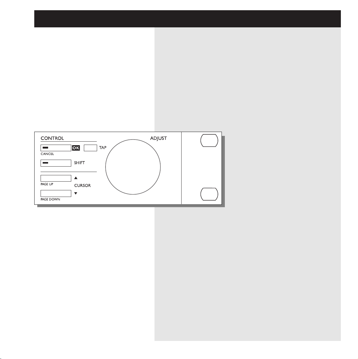
SETUP SECTION
I/O
Input/output
Samplerate
Digital/analog selection
Dithering.
Routing
Setup the internal routing of the 2
engines.
Levels
Input/output analog levels
Digital input level
Util/Midi
Viewing angle
Security lock
Preset handling
Pedal input
MIDI
Secondary functions
Help
(online help function)
Tuner (the tuner you always wanted)
Auto level
(the fast way to set input levels)
Midi monitor (Monitors all midi ch. at the same time)
PPM + INDICATORS
PPM meters
range from -40dB to 0dB
Overload
Lights up if internal overload occurs.
SampleRate indicator
48000Hz
44100Hz
32000Hz
Midi In
Midi receive indicator
Card
Indicates presence of a
valid memory card
Tempo
Beats per Minute indicator
Morphing
Indicates an on-going morphing
POWER + MEMORY CARD
Electronic power switch
»Easy touch«
Keep pressed for more than
1sec to turn device off.
PC-CARD memory card
Copy presets to/from a standard memory card.
Page 7
7
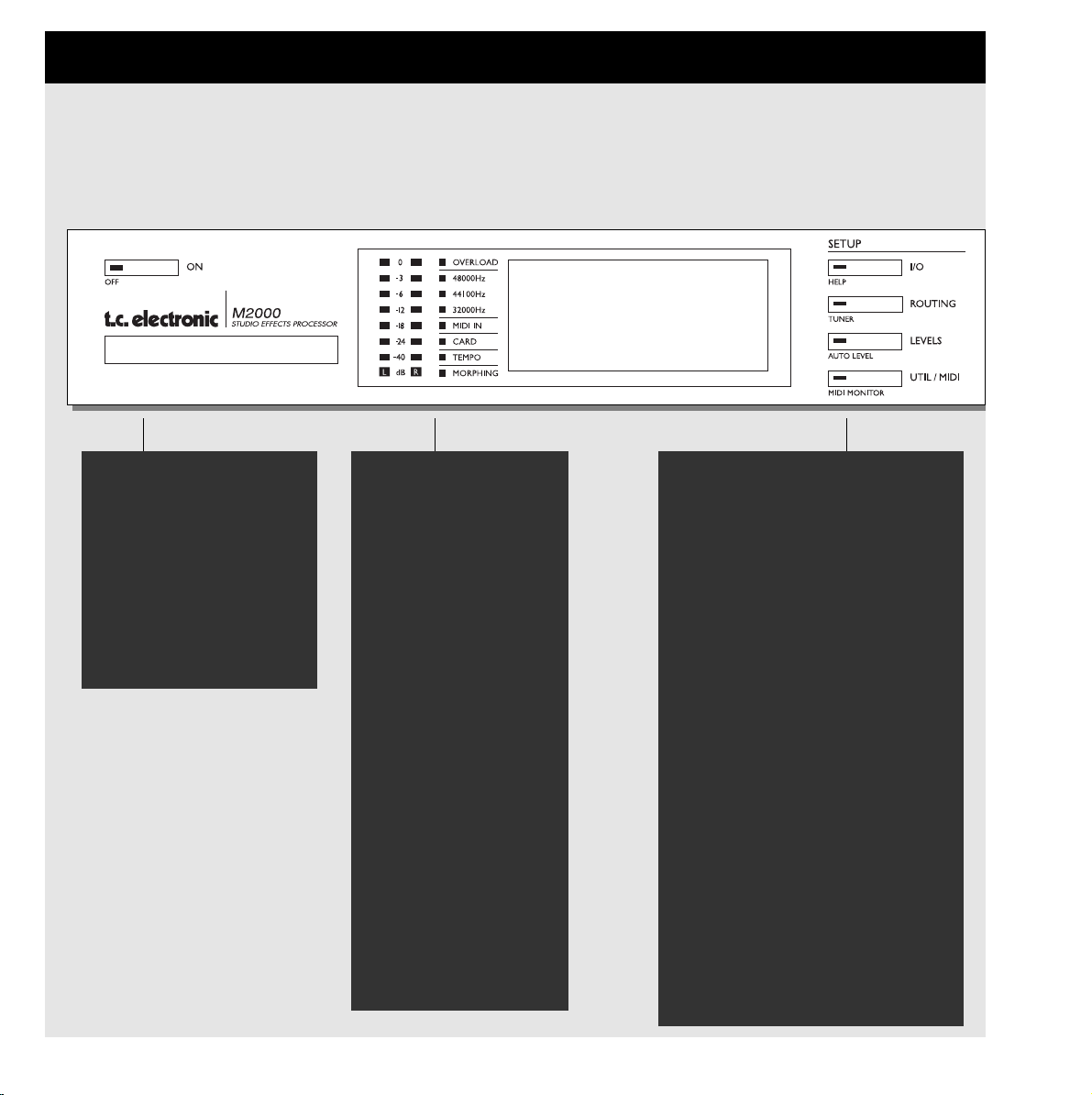
ENGINE 1 OR 2
Recall
Recall presets to engines
Store
Store and name presets.
Edit
Edit engine 1 or 2
Bypass
Individual bypass key for
each engine.
Second functions
Recall Wizard
Find a preset that match your application
Delete Preset
The fast (and only) way to delete presets
COMBINED 1+2
Recall
Recall combined presets.
Store
Store and name combined
presets
Edit
Engine mix level
Dynamic Morphing
Bypass
Bypasses the entire device.
Snapshots 1-4
Quick store/recall of combined presets
Second functions
Recall Wizard
Delete Preset
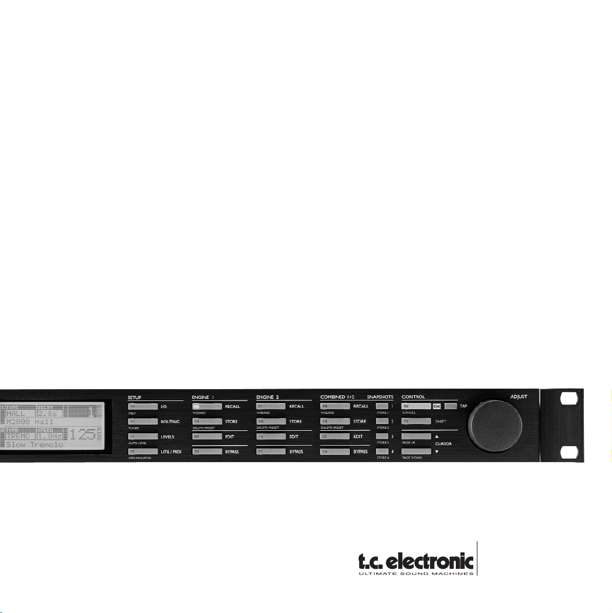
CONTROL SECTION
OK
Confirms operations.
Shift
Enables access to »shifted«
secondary functions.
Cursors
Moves between parameters
Adjust wheel
Sets parameter values and
preset numbers.
Second functions
Cancel
Page up/down
Page 8
8
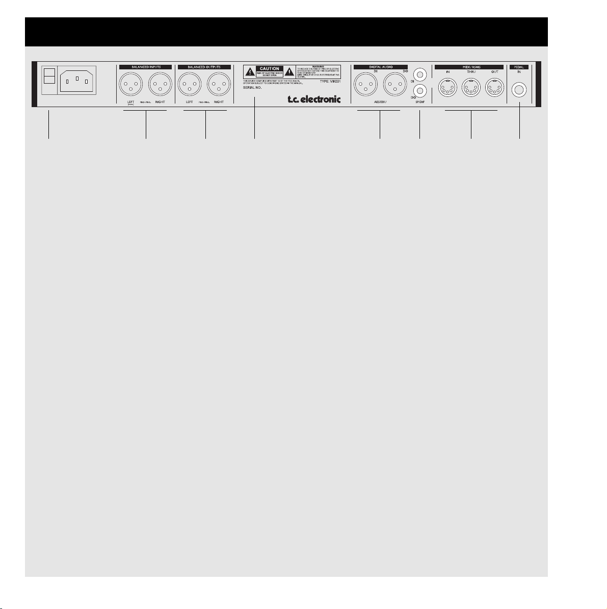
THE REAR PANEL
Main
Power
Switch
Balanced
XLR
Inputs
Balanced
XLR
Outputs
Serial no.
AES/EBU
Digital
in/out
S/PDIF
Digital
in/out
MIDI
In,Thru,Out
Pedal
Input
Notes:
To accomodate International regulations, we have also added a back panel power switch.
You don’t need to use the power switch on the rear panel. Use the front panel power switch instead.
Remember to use the left input when you’re using only one input.
Pin 2 is »hot« on all XLR’s (AES Regulations).
If You are connecting the M2000 to unbalanced equipment, you must tie pins 1 and 3 together in the cable
ends away from the M2000.
We have reserved the two unused pins on the MIDI connectors for an optional RS485 interface. Therefore, if
you are connecting M2000 to other equipment that use these pins, please make sure the cable is a 3-wire
standard MIDI type, and not a five wire MIDIPLUS type.
If you want to use the pedal input, be sure it is a momentary »make« type.
Page 9
9
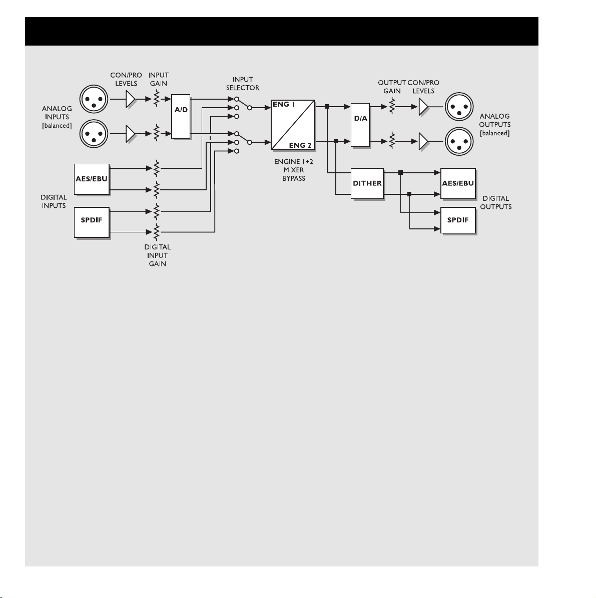
THE SIGNAL FLOW
Notes Regarding the signal flow:
As shown in the block diagram signals are present on all outputs, all the time.
The digital input gain circuit is capable of »lifting« the signal level. This is a very useful feature if you e.g.
are feeding the M2000 with a DAT recording that isn´t fully leveled to 0 dB.
Page 10
10
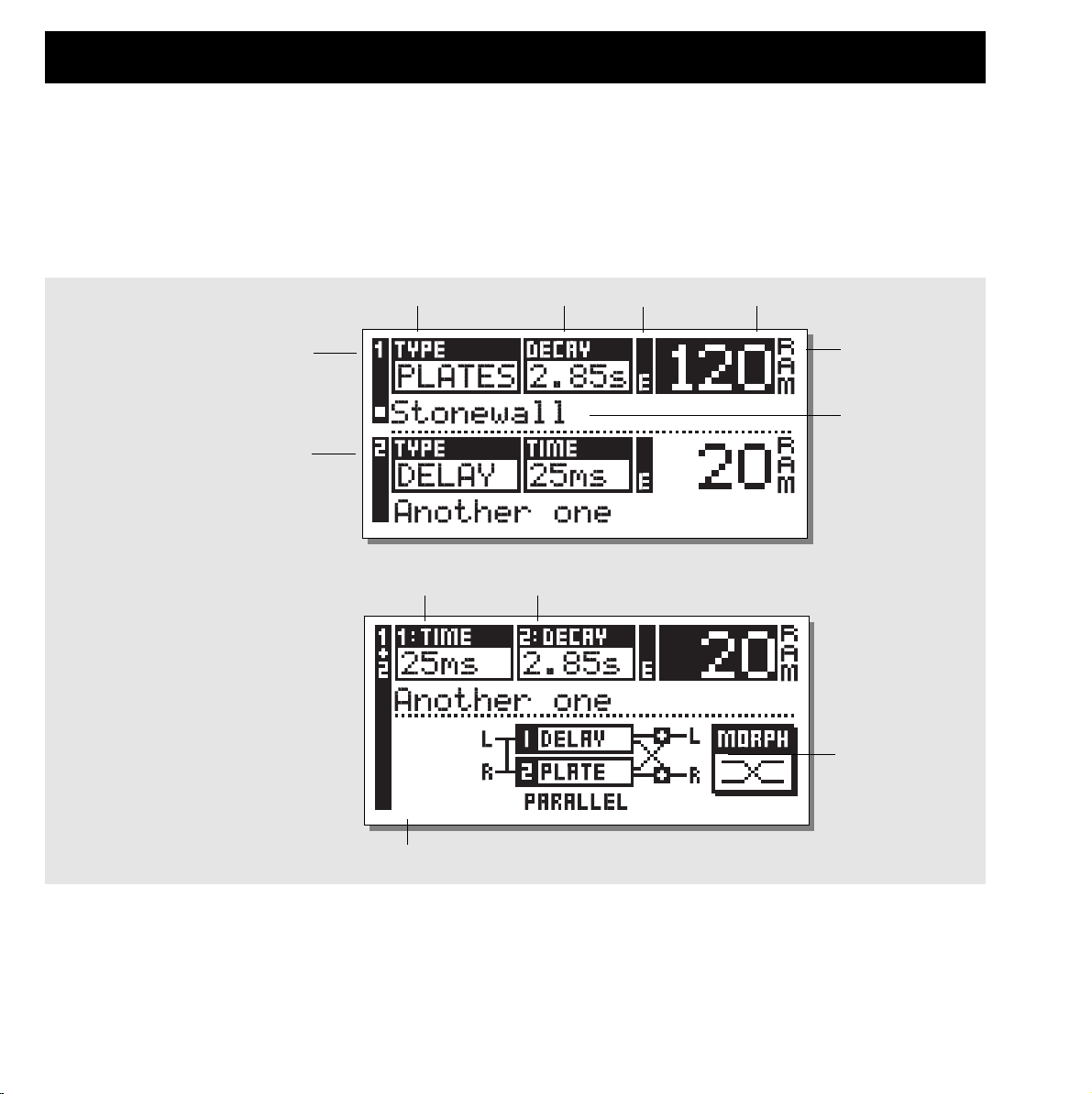
RECALL + SNAPSHOTS
Bank indicator
(RAM/ROM)
Engine 1
Engine 2
Algorithm type Primary parameter Edited flag Preset number
The Recall Displays
The Recall display is the »homepage« of the M2000. This means that you return to this display whenever you exit any other display of the
M2000.
The Recall display is split into two halfs, showing the presets of both Engines at the same time. Engine 1 is always the top half while
Engine 2 is the bottom half of the display.
If you want to have only one effect, use one engine and set the other in bypass mode.
Recalling a Preset
When you wish to Recall a preset, simply use the
ADJUST wheel to scroll through the presets and press
OK to Recall.
Another way of Recalling is to use the Wizard described later in
this section (see »The Wizard«). The Preset number and the OK
key will be blinking while you are previewing, indicating that the
shown preset is not Recalled yet.
Use the Cursor keys (or the other Recall key) to access the other
Engine.
Primary parameters
Preset name
Recall Display
Combined Recall Display
Routing mode
Flag indicating change to a new routing (only visible during preset preview)
Page 11
11
Preset banks
NORMAL
Factory presets
Your own presets
COMBINED
The M2000 contains four different preset banks. Each bank can
hold 128 presets.
The four banks are as follows:
Normal ROM bank:
This bank contains 128 normal factory presets. The presets are
available from Engine 1 and Engine 2.
Combined ROM bank:
The Combined bank contains 128 Combined factory presets. The
Factory/User Presets
presets are available from the Combined Recall.
Normal RAM bank:
This bank can hold up to 128 of your normal presets.
Combined RAM bank:
The Combined Ram bank can hold up to 128 of your Combined
presets (see Combined presets).
The two Ram preset banks are located after the corresponding
Rom banks . This means that you scroll through the 128 Rom
presets to enter the Ram bank.
For fast RAM access press shift and turn Adjust
wheel one click to the right.
The Preset number and the OK key will be blinking while you
are previewing, indicating that the shown preset is not Recalled
yet.
A Combined preset is made out of two normal presets. This
means that when you return to the normal Recall display (the
Homepage) the M2000 will display the numbers and names of
the two presets that the Combined preset consists of. The Edited
flag will light if the presets have been modified.
Combined Recall
The M2000 is capable of Recalling Combined presets, meaning a
preset for each Engine in a combination.
A Combined preset consists of two normal presets and the
Routing of the M2000: i.e. by Recalling Combined preset 30, a
Chorus will be loaded into Engine 1; a Reverb will be loaded into
Engine 2, and the Routing will change to Serial (see »Routing«).
To Recall a Combined preset:
Press the Combined Recall key and scroll through the
presets using the Adjust wheel. Press OK when you
find the right preset.
128 RAM
PRESETS
128 ROM
PRESETS
128 RAM
PRESETS
128 ROM
PRESETS
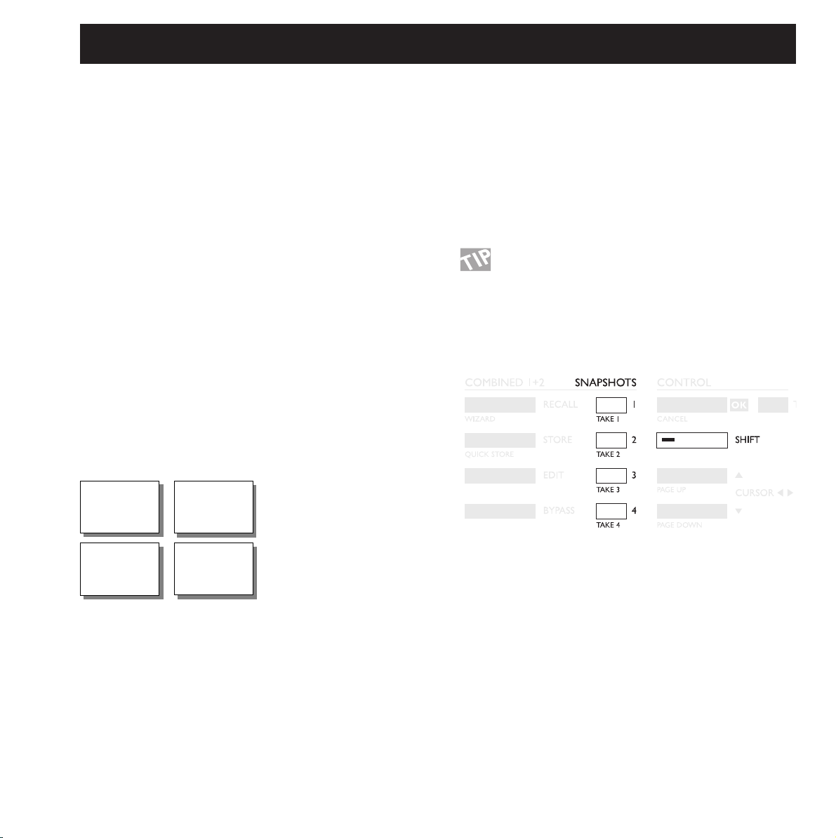
A Snapshot will always include both Presets, and Routing just
like a Combined preset.
With the Snapshots you are able to switch between completely
different configurations with the touch of a single key.
TAKING A SNAPSHOT:
When you want to Take a Snapshot of your M2000 setup, press
Shift and the Snapshot key where you want to store.
RECALLING A SNAPSHOT:
Recall of a Snapshot is very easy as well: Simply press the
Snapshot you wish to Recall and the M2000 will change the
whole setup.
Snapshots
The Snapshots are fast Recall keys. Store your favorite
presets or use the Snapshots as four compare keys.
Page 12

12
STORE
Store a new RAM Preset
- Press the STORE button [Engine 1, 2 or combined]
- Select a location for your new preset [dial between preset 1 to 128]
- Move cursor to the new name line and dial in the new preset name [find letter with ADJUST and confirm with OK ]
- Point on DONE and press OK to finalize store operation.
Store with the same name:
If you want to Store the Preset with the existing name simply select the RAM location to Store in by using the ADJUST wheel and press
OK (the OK key will be blinking while you search for a suitable RAM space). The M2000 will now tell you “STORED” in a pop-up window and return to the homepage.
Store location
The letterbox
When you want to change the name of the preset to Store, press
the Cursor Down key. You are now able to write a new name
using the letterbox. Simply dial the ADJUST wheel and press OK
to select new letters.
Select CAP, by pressing OK, to change case.
When you have changed the name select DONE in the Letterbox
and press OK to Store.
Combined Store
The handling of Combined Store is exactly the same as a normal
Store.
Please note that a Combined Preset Stores the Routing of the
Engines along with the Preset.
New preset name
Letterbox
Cursor arrows
CAPS LOCK
Indicator
Place cursor here and press OK
to finalize store operation
Using a Memory Card:
When you wish to use a Memory card, simply insert the Card in
the M2000. The M2000 will now autodetect your card and the
Store, Recall and Snapshot facilities will be attached to the
Memory card. The M2000 will now use the Memory Card as a
normal RAM bank. When you remove your Memory card the
M2000 will switch back to the internal RAM.
If the format of the Memory card is not correct, the M2000 will
detect this immediately.
Card types
Type 1 PC-CARDS, with minimum 64KBytes SRAM.
Page 13
13
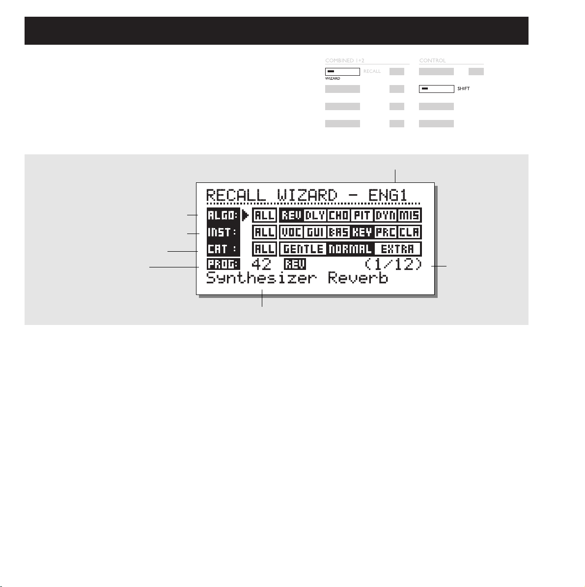
THE WIZARD
Press Shift and Wizard to enter the function
Use the parameter keys to select the different filters
and the Adjust wheel to select filter parameters.
Set the three different categories as you desire and try out the proposed presets. The Wizard will show the Name and Number of the
proposed preset.
Scroll through the Presets using the Adjust wheel and press OK to
Recall.
You can use the Wizard in many different ways, i.e., set it to enter
only Drum Reverbs or use it as a creative partner.
Algorithm types
Reverb
Delay
Chorus (including flanging and phasing)
Pitch
Dynamic (compressor/limiting/expanding/deessing)
Misc.
Instruments
Vocals
Guitars
Bass
Keyboards
Percussion
Classic instruments (violins, flutes, etc.)
Category
Gentle
Normal
Extra
The Wizard is a tool that helps you find the right preset
for your program material.
The Wizard is easy to access and simple to use.
Try it out, and listen what our creative staff suggests
for your program material.
1. Select the type of effect you want
Engine 1 or 2
2. Which instrument to be used on
3. and the category of intensity
Dial here to select between
presets that utilize the search
criteria.
Name of selected preset
Number of presets utilizing the
search criteria
The Wizard Display
How to enter »The Wizard«
Page 14

14
I/O
Press the I/O key to setup various I/O parameters.
Move the marker using the Cursor keys and turn the ADJUST
wheel to change values.
Input
Select Input source Analog/Digital.
Select Input type Left/Both. When you select Left the right input
will be muted. If you are using two inputs you should select Both
Sample rate
Select Master clock 44.1 kHz/48 kHz/DI.
When Digital Input is selected, the external Clock frequency will
be displayed by the three LEDS on the left side of the Display. If
the M2000 cannot lock, all three LED’s will be blinking.
Mix
The Mix is a global parameter. When Mix is set to “100%” the
Mix parameter of all presets will be 100% and no direct signal
will pass through the M2000. Note that when Mix is set to 100%
the Bypass keys will act like Mute-keys.
When Mix is set to “Mix”, the parameter is adjustable.
Press the I/O key to setup various I/O parameters.
Move the marker using the Cursor keys and turn the ADJUST wheel to change values.
Status Bit:
This selector changes the Channel Status Bits of the digital output
between professional and consumer format. When AES is selected, the M2000 will output the professional AES/EBU standard,
and when S/PDIF is selected, the M2000 will output the S/PDIF
consumer standard.
The defaults setting is AES/EBU but some digital consumer
products refuses to accept the professional standard.
In that case change to S/PDIF consumer standard.
Example: If you are using a non-professional DAT machine as a
receiver of the M2000 digital output, and you cannot make it
accept the digital input, change the output format from AES/EBU
to S/PDIF.
NOTE: The different Status Bit standards do not affect the quality
of the audio output from the M2000.
Dither:
The M2000 can output Dither from 8 to 22 bit resolution on the
AES/EBU and S/PDIF ouput. The dither type is HP-TDF or High
Pass Triangular probability Density Function.
M2000 uses internal 24 bit resolution and 24 bit AD/DA
converters. Dither should therefore only be used when the digital
outputs are used (e.g. to a 16 bit DAT machine). It is
recommended not to use dither until the final stage of a
production, so if there is a chance that the source material is
going to be dithered later in a production, do not use Dither.
Here you can freeze mix to 100%
Select Status Bit output:
SP/DIF OR AES/EBU standard.
Sample rate:
44100Hz,
48000Hz or
from digital inputs
Indicates the number of bits
digital output are dithered to.
Automatically set to default value,
when changing Status Bit.
Input Selector
Input Signal
I/O
Page 15

15
Press the Level key to access this menu.
These global level controls should be set to optimize the performance of the 24bit AD converter in the M2000.
The Level bars can be controlled individually or in common.
Mark the level bar you want to control using the cursor keys, and turn ADJUST to change value.
For common control the marker should be set between the two Level bars.
Note that the Digital In Level is capable of +6 dB gain.
Digital input gain
Place cursor between L and R to adjust simultaneously
Input gain
and sensitivity
(Consumer/PRO)
Output gain
and level
(Consumer/PRO)
LEVEL MENU
Ranges
Analog Inputs
Consumer range: -16dB to +10dB
Professional range: -6dB to +16dB
Analog Outputs
Consumer range: -10dB to +16dB
Professional range: -16dB to +6dB
Digital Input Level
Adjust the Digital Input from: Off to +6dB.
Auto level
Press SHIFT and AUTO LEVEL to activate function.
Send your expected source into the M2000 and press Auto Level
(Shift-Levels) to optimize your Input level automatically. The
M2000 will perform a measure for about five seconds and then
adjust the Input level giving you about 6 dB of headroom.
Page 16

16
Serial
The Serial mode is a Stereo In/Out
Routing. The Serial mode is very useful
when you want two independent effects
in the same signal path; i.e., from a
Keyboard through the M2000 Reverb and Chorus to The mixer.
Parallel
The Parallel mode is a stereo In/Out
Routing. Both Engines will work as stereo
effects and their Output will be mixed
down to a stereo signal. With this Routing,
the M2000 can be used as two parallel effects on the same stereo
source. You may also set the I/O menu to left input to get two independent stereo-out effects on the M2000 from a single send on the
mixer.
Dual input (Split mode)
The Dual input mode is a Dual mono In /
stereo Out Routing. Left In is always
attached to ENGINE 1 and Right In is
attached to ENGINE 2. Using this Routing enables you to get two
different effects with separated inputs; i.e., connect Aux 1 from
your Mixer to Left In and Aux 2 to Right In. You now have
access to two separate effects with a common stereo output. Set
the individual Preset output volumes to achieve the correct effects
balance.
Dual Mono
This mode is for Dual Mono In/Out
Routing. Left In/Out is always ENGINE 1
and Right In/Out is ENGINE 2. The Dual
Mono is very useful when you want to
use the M2000 as two independent Inserts.
Stereo
When you select the Stereo Routing, the
two Engines will link together to perform
true Stereo. This means that the preset of
Engine 1 will be copied into Engine 2 and
the Edit pages will lock together. The Stereo Routing is indicated
by the two Edit LEDS which will be lit simultaneously. Left and
Right channel audio path are completely separated in this
Routing.
Preset Glide
When the Preset Glide Routing is se-
lected, the M2000 will perform preset
changes by crossfading the current Effect
and the new preset. This gives you a very
smooth change of effects; i.e., allowing a Delay to keep repeating
while a Chorus is being faded in.
The glide time is located in the Utility menu (see Util/MIDI).
Please note that only one Engine is available while the M2000 is
in the Preset Glide Mode.
ROUTING
Pressing the Routing key gives you the ability to choose one of six different Routings.
Move the marker by pressing the Cursor keys and press OK to accept the new Routing.
A small pop-up window will tell you that the Routing has changed.
Page 17

17
STUDIO SETUP EXAMPLES
Use two sends on your mixing console
Dual Input mode
Let’s say Engine1 is running a long Hall-type reverb and Engine 2 a short more ambient type
of reverb. On Your mixing console you’ll now have individual sends for the two effects.
And - not to forget - you are saving a set of return channels.
Create your own vocal reverb
Serial mode
You probably always wanted to have a long bright reverb on your lead vocal, without
»esses« hanging for seconds. That’s now possible. You simply connect a »de’esser« and your
favorite reverb in serial. The de'esser will cut away all sharp transients in the signal.
If you want your vocal to have a unique »livingness«, or the reverberated signal to be slightly
detuned, simply connect the pitch shifter or chorus in series with the reverb.
There are numerous applications in this mode - try them out.
Two individual inserts on your mixer
Dual mono mode
In the dual mono mode you are able to use two completely separate mono effects at the same
time. It can be equalizers or compressors or whatever you can imagine.
Post Production
Stereo mode
When running in stereo mode both engines are linked in stereo and both channels audio path
are totally separated. This means that you can process Dolby Surround™ materials without
destroying the hidden information. Use this mode when adding reverb to your recording.
Page 18

18
UTIL/MIDI
Display
Viewing Angle:
Adjust for best contrast on the LCD display.
Preset glide:
Glide time
This parameter sets the glide time of the incoming preset. The
parameter is only active when Preset glide Routing is selected
(See Routing).
In the MIDI section you are able to see the MIDI setup
of both Engine 1, Engine 2 and the Combined section
at the same time.
MIDI In
Channel
Sets the Channel of which the current Engine will respond to.
When set to Omni the Engine will respond to all channels, When
set to off no MIDI will be received.
Filter
Sets whether the current section of the M2000 should respond to
MIDI Control changes (CTRL) and MIDI Program changes
(PROG) or not; i.e., when Filter is set to PROG the M2000 will
only respond to MIDI Program changes.
Offset
With this parameter, you are able to add or subtract to the incoming Program change; i.e., the incoming Program Change is preset
123, and the Offset is set to +1, the Program Change will now be
124.
Sys-ex id
Sets the Sys-Ex ID number of the M2000.
How to move around
In the Util/MIDI menu you always move by pressing the
Cursor keys and change values by dialing the Adjust
wheel.
Page 19

19
Memory Protect
Protect
This parameter sets the Memory protect On or Off. When the
Protect is activated the Ram presets inside the High and Low
limit are write protected.
Low Lim
Sets the Low limit of the Memory protect. The current number is
included in the Protect.
High Lim
Sets the High limit of the Memory protect. The current number is
included in the Protect.
Snapshot Protect
Enables or disables the Protect of the Snapshots. When activated
the Snapshots are write protected.
Memory Backup
Mem > Card
Insert a PC-CARD Card in the card-slot and press OK. All Ram
presets of the M2000 will now be backed up to the Memory
Card.
Card > Mem
Insert the PC-CARD Card containing your presets and press OK.
All Presets will now be Stored back into the M2000 Ram.
Warning:
This action will destroy ALL existing Ram Presets of the M2000.
Mem > Midi
Connect your M2000s Midi Out to a another M2000, a
Sequencer or any other Midi Recordable device. Press OK and
the M2000 will perform a Midi bulk dump of all Ram Presets.
Midi > Mem
Connect the Storing device to the M2000s Midi In and press OK.
The M2000 is now ready to receive a Midi bulk dump containing
Ram presets. WARNING this action will destroy ALL existing
Ram Presets of the M2000.
Pedal
Pedal
The Pedal input can control any one of four different features:
Engine 1 Bypass, Engine 2 Bypass, Engine 1+2 Bypass and Tap
tempo.
Select by turning the Adjust Wheel.
MIDI Out
Channel
Sets the sending MIDI channel of the M2000.
Filter
Sets wether the current section of the M2000 should send out
MIDI Control changes (CTRL) and MIDI Program changes
(PROG) or not; i.e., when Filter is set to PROG the M2000 will
only send out MIDI Program changes.
Offset
With this parameter you are able to add or subtract to the outgoing Program change; i.e., the outgoing Program Change is preset 123, and the Offset is set to +1 the Program Change will now
be 124.
MIDI Map
MIDI Map
Sets the current MIDI Map On or Off.
Prg. Bank
Determines which Bank the MIDI Map should control;
Ram/Rom.
Prg. In
The current Program change Maps to a M2000 program (See
Maps to).
Maps to
The current incoming Program change set in “Prg. In” will be
changed to the Program number of this parameter.
Reset Map
Press OK while this parameter is selected and your MIDI Map
will be Reset.
Security
Security Lock
Press OK while this parameter is selected to Security lock the
M2000. When locked, you will have to dial the PIN-Code shown
below to access the M2000.
PIN-Code
Set your own PIN-code for the Security lock by Dialing the
Adjust Wheel.
If you should forget your PIN-code, please enter the Reset page.
This will release M2000 from the locked state. (You do not have
to run any of the reset functions).
Page 20

20
TEMPO
Tapped time in ms.
Tapped or dialed BPM
Which engine to work on
Define subdivision beat
Tapped time in ms.
corrected with
the subdivision factor.
Tap Tempo
The Tap Tempo key is similar to its cousin “Learn” on the TC
2290 Digital Delay. Only the M2000 Tap Tempo key can control
various parameters: Delay time, Decay time, Chorus speed, etc.
When you press the Tap key, a Tempo menu pops up. If no further
actions are made, the Tempo menu will disappear after a few seconds.
The Tap key is attached to a default parameter in each effect type.
This means that the function of the Tap key changes along with
the presets (See default list later in this section).
The Tempo Menu
The Tempo you tap is always measured in BPM (Beats Per
Minute). The Tempo menu is able to recalculate the tapped time
into Subdivisions of the BPM. Simply set the Tempo menu to the
Subdivision you like and Tap the BPM on the Tap Tempo key.
You also have the possibility of changing the Tempo using the
BPM parameter in the Tempo menu. When a preset has been
“Tapped”, the parameter attached to the Tap function will be displayed in BPM in the Tempo Menu.
Tempo BPM
The BPM will display the Tapped tempo (BPM is equal to the 1/4
Subdivision). You can also set your Tempo with this parameter
using the ADJUST wheel.
Subdivision
Sets the subdivision of the Tempo. If the Subdivision is set to 1/8,
the actual Tempo will be twice as fast as the tapped time, etc. The
following subdivisions are possible:
1,1/2,1/4,1/4T,1/8,1/8T,1/16,1/16T,1/32,1/32T (T for triplets).
Tap/Subdivision
This is read only parameters displaying the tapped time and the
Subdivided time in milliseconds. Tap Time Subdivision is corresponding to the parameter in your preset.
The parameters controlled by the Tap key
Reverb Decay parameter
Delay Delay time
Chorus Speed
Flanger Speed
Phaser Speed
Tremolo Speed
Panner Speed
Press and hold TAP for 3 seconds to learn MIDI
tempo (MIDI-Clock).
Page 21

21
MIDI MONITOR & TUNER
Tuner
Press Shift - Routing to access the Tuner of the M2000.
When Tuner is selected, the Outputs will be muted.
Select Guitar/Bass/Manual mode by turning the ADJUST wheel.
When Guitar or Bass is selected, the Tuner will only respond to
notes corresponding to the strings of these instruments.
When set to Manual, you must select the desired Note using the
ADJUST wheel.
In the Master section, you can Calibrate the Tuners default, 440445 Hz.
The detected note will be shown in the lower right corner and in
the note line. When the horizontal marker is 0, you are tuned in.
The two tuning guides will tell you wether the note is too flat or
too sharp.
Press any key to exit Tuner.
MIDI Monitor
Press Shift - Util/Midi to access MIDI Monitor.
In the MIDI Monitor, you are able to see all MIDI actions
received by the M2000. The actions are displayed according to
the current channels.
Prog. Displays Program changes.
Note Displays Note On/Off.
Cntl Displays Control changes
Sys-x Displays System exclusive commands
Eng Displays the midi channels of Eng 1,2 and combined.
Chan Displays the Midi channels
Press any key to exit MIDI Monitor.
Program changes
Channel pointer
Tuning guide
Tuning guide
»MIDI MONITOR SCREEN«
»TUNER SCREEN«
Note on/off
Controllers
System exclusive
Engines MIDI channels
Select guitar/bass
or note set manual
Master tune 440-445Hz
Detected note
Deviation in cents
Page 22

22
EDIT
Combined Edit
See illustration on next page
The relative Levels of the two Engines can be adjusted in this
display. The range is: off - 0.0 dB.
These levels affect both analog and digital outputs.
Move the marker by pressing the Cursor keys; change values
using the Adjust wheel.
The Engine Out Levels are identical with the Outlev. parameter
in the Edit page and will, at all times, be corresponding with
these.
Edit
In the Edit menu, you always move by pressing the Cursor keys
and change values by dialing the Adjust wheel.
Expert mode
When pressing OK on the Expert line, the M2000 will enable you
to access a detailed Edit mode of the Reverbs.
Since the two different Edit modes (User & Expert) are not compatible, it is NOT possible to return to the User Edit mode. When
Storing a preset Edited in Expert mode, the current preset will
remain in expert mode forever.
Values
Subtitles
Parameters
Algorithm been edited
Page 23

23
DYNAMIC MORPHING
Dynamic Morphing
The Dynamic Morphing function is a great new way of interaction between your source signal and the Effect.
When activated, the M2000 will morph between the two Engines
according to your Input level. This is a function for quick seamless changes of an Effect.
Think about the vocal in a ballad being soft and subtle during the
verse and then rising to heartbreaking heights in the chorus. Now
imagine the Reverb changing along with it, from a small discreet
Room in the verse, to a Big Bright Hall in the chorus.
Simply select the two presets in the current Engines and then
activate the Dynamic Morphing function. Set the Threshold and
the Speed of the Dynamic Morphing and check out the result.
Morph direction 1-2:
If this box is selected, Engine 1 will be active while the Input is
below Threshold.
Morph direction 2-1:
If this box is selected, Engine 2 will be active while the Input is
below Threshold.
Note that the max. level of the Engines is set by the Engine Out
bars above Dynamic Morphing.
The Dynamic Morphing is Stored along with Combined Presets.
The Dynamic Morphing function is only available when Routing
is set to Parallel.
Engine output levels
Engine output levels [mix]
Dynamic Morphing section
Morphing threshold
Morphing speed
Morphing on/off and
morphing direction
Page 24
24
THE PROGRAMS
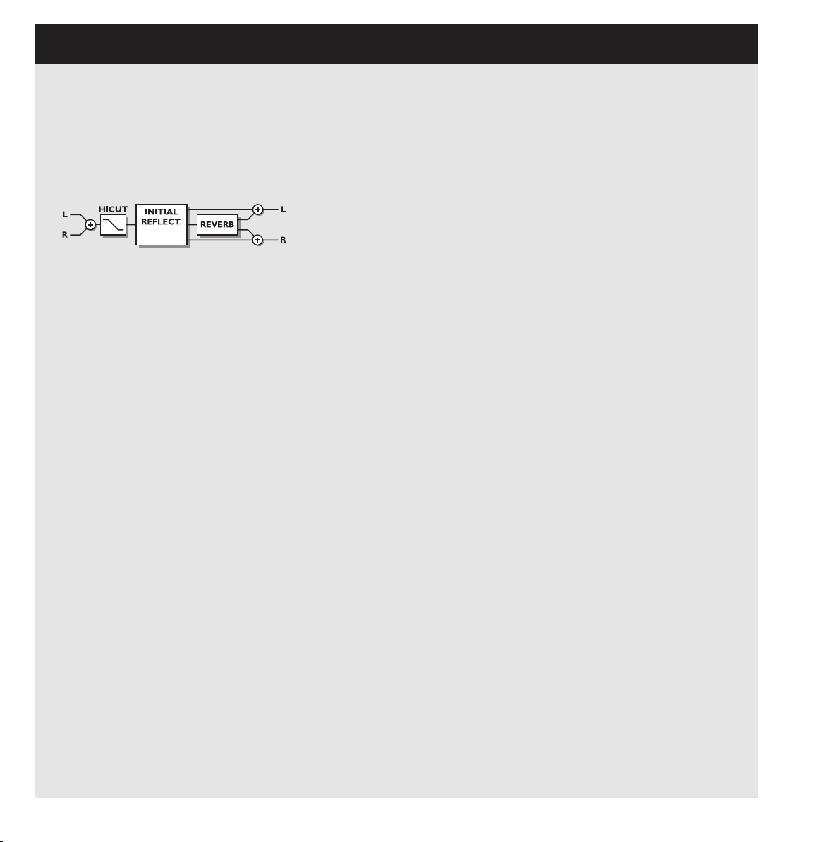
Reverb Programs
HALL-ROOM-PLATE-AMBIENCE-GATED
All Reverb presets both have a User and an expert page.
The number of parameters depends on which preset you
have selected.
USER PARAMETERS
Decay
Sets the decay time. The value indicates the time to where
the reverb tail is damped to -60dB.
Pre-delay
The time to arrival of the first reflection.
Reverb Lo
Adjust the low frequency reverberation time.
Reverb Mid
Adjust the mid frequency reverberation time.
Reverb Hi
Adjust the high frequency reverberation time.
Expert mode
Press OK here to enter expert mode. Remember there is no
way back to normal user parameters, after adjusting any
expert parameters.
HiCut freq.
Sets the cutoff frequency of the HighCut filter.
HiCut level
Damping ratio in dB of the HighCut filter.
Mix
Mix between direct and effect.
Out Level
Adjust output level. Use this parameter to match levels
between presets.
EXPERT PARAMETERS
(only additional parameters mentioned)
Diffuse
This parameter sets the degree of wall diffusion. Increasing
the value will result in a more dense reverberation tail. Don’t
set the value too high, as it will result in a not natural sounding reverberation tail.
Room shape
Here you can choose between different room shapes.
Changing the room shape will change the initial reflections.
Size mult.
Size multiplication factor. With this parameter you can
change the size of the room. Only the initial reflections are
influenced by this factor.
Lo Crossover
Crossover frequency between low and mid band reverberation filter.
Mid Crossover
Crossover frequency between lo-mid and hi-mid band reverberation filter.
Hi Crossover
Crossover frequency between mid and high band reverberation filter.
Initial lev.
Sets the Initial reflection level.
Rev.lev.
Level of the reverberation tail.
Rev.width
This parameter adjust the stereo width of the reverb tail.
Rev Feed
Determines how fast the reverberation will build up.
Rev.diff
Imposes the characteristics of the early reflections on the
later reverberation.
Distance
The relative distance control varies the mix relations
between early and later reflections. Simulating how far away
you are from the sound source.
Difusor type
The natural room mode peak frequencies and the smoothness
of the tail are affected by this parameter.
Mod Rate
The MODRATE varies the rate of modulation of the recirculating delay paths simulating the reverb tail.
Mod Depth
Controls the amount of delay path modulation or "wander"
in the reverb.
Page 25

25
Chorus Programs
These presets are capable of producing a smooth natural
sounding stereo chorus effect. The Hicut filter gives you
the ability to make it sound very warm.
USER PARAMETERS
Speed
Controls the rate of sweep in a range from 1 sweep every 10
seconds to 10 sweeps every second.
Depth
Determines how wide a modulation (sweep) is produced.
Phase
Determines the sine wave modulation phase shift between
left and right channels. At 0º the left and right modulation
will move in sync. At 180º the modulation will move the
channels against each other.
HiCut Freq.
Hicut shelving type filter (6dB/oct). This parameter sets the
»hinge« point of the shelving filter.
HiCut Level
Sets maximum depth of cut above the HiCut shelving frequency.
Delay
Controls the length of delay time.
Mix
Mix between direct and effect.
Out Level
Adjust output level. Use this parameter to match levels
between presets.
Flanger Programs
The Presets range from very soft add-on effects to the
wildest guitar sound you can imagine. The Feedback filters
are capable of controlling both high frequency and low frequency feedback.
USER PARAMETERS
Speed
Controls the rate of sweep in a range from 1 sweep every 10
seconds to 10 sweeps every second.
Depth
Determines how wide a modulation (sweep) is produced.
Phase
Determines the sine wave modulation phase shift between
left and right channels. At 0º the left and right modulation
will move in sync. At 180º the modulation will move the
channels against each other.
FB Level
Controls the amount of effect signal routed back to the
flanger inputs. Select negative feedback to change feedback
phase.
Delay
Controls the length of delay time.
FB HiCut
Feedback High Cutoff frequency. Signal is damped 6dB/oct
above this frequency.
FB LoCut
Feedback Low Cutoff frequency. Signal is damped 6dB/oct
below this frequency.
HiCut Freq.
(see chorus)
HiCut Level
(see chorus)
Mix
Mix between direct and effect.
Out Level
Adjust output level. Use this parameter to match levels
between presets.
Page 26
26
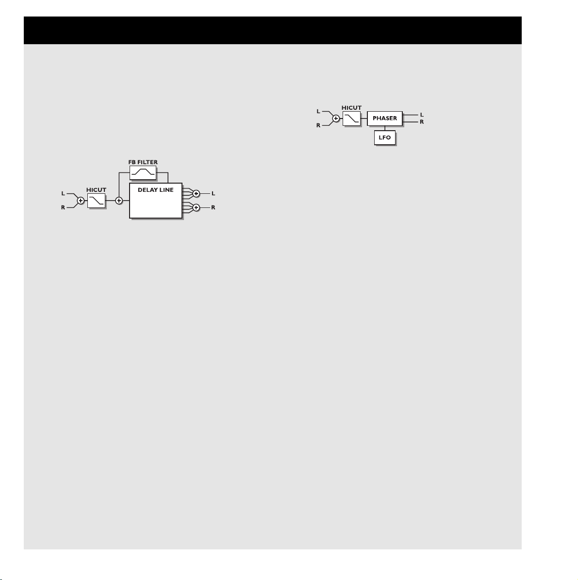
Delay Programs
The Delay presets are capable of performing up to 1200 ms
delay. The Feedback filters makes it possible to control both
high and low frequency feedback.
USER PARAMETERS
Delay
Controls the length of delay time.
FB Level
Controls the amount of effect signal routed back to the input.
FB HiCut
Feedback High Cutoff frequency. Signal is damped 6dB/oct
above this frequency.
FB LoCut
Feedback Low Cutoff frequency. Signal is damped 6dB/oct
below this frequency.
HiCut Freq.
Hicut shelving type filter (6dB/oct). This parameter sets the
»hinge« point of the shelving filter.
HiCut Level
Sets maximum depth of cut above the HiCut shelving frequency.
Mix
Mix between direct and effect.
Out Level
Adjust output level. Use this parameter to match levels
between presets.
Phaser Programs
USER PARAMETERS
Intensity
Phaser intensity.
Speed
Controls the rate of sweep in a range from 1 sweep every 10
seconds to 10 sweeps every second.
Depth
Determines the depth of modulation.
HiCut Freq.
Hicut shelving type filter (6dB/oct). This parameter sets the
»hinge« point of the shelving filter.
HiCut Level
Sets maximum depth of cut above the HiCut shelving frequency.
Mix
Mix between direct and effect.
Out Level
Adjust output level. Use this parameter to match levels
between presets.
THE PROGRAMS... continued
Page 27

27
Multi Pitch-shift Programs
The Multi pitch presets are capable of performing 6
pitched Voices at the same time. This makes it possible to
produce a true chorus effect.
USER PARAMETERS
Mix
Mix between direct and effect.
Out Level
Adjust output level. Use this parameter to match levels
between presets.
Voice
Sets which voice you are editing.
Pitch
Sets the pitch of the current Voice (0-1200).
Level
Sets the level of the current Voice.
Pan
Sets the panning of the current Voice.
Delay
Sets the Delay of the current Voice.
Page 28
28
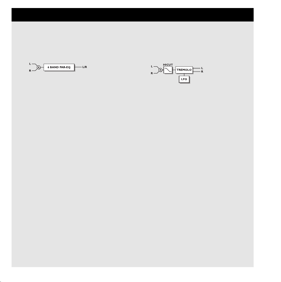
EQ Programs
The EQ programs are all 3 band parametric types with separate high and low shelving bands.
USER PARAMETERS
Frequency
Low shelving filter ranges from 20hz to 5Khz
High shelving filter ranges from 500hz to 20Khz
Three band filters ranges from 20hz to 20Khz
Band width
Low and high shelving filters have 2 different bandwidths
The 3 bandfilters have 3 different bandwidths
Level
All filters range +/- 12dB.
EQ level
Adjustable +/-12dB.
Tremolo Programs
The Tremolo programs are effects where the output level is
modulated by an LFO. Our programs are able of setting the
LFO phase between the two outputs.
USER PARAMETERS
Speed
Controls the rate of sweep in a range from 1 sweep every 10
seconds to 10 sweeps every second.
Depth [intensity]
Determines how wide a modulation (sweep) is produced.
Phase
Determines the sine wave modulation phase shift between
left and right channels. At 0º the left and right modulation
will move in sync. At 180º the modulation will move the
channels against each other.
Mix
Mix between direct and effect.
Out Level
Adjust output level. Use this parameter to match levels
between presets.
THE PROGRAMS... continued
Page 29

29
Stereo Programs
USER PARAMETERS
Spatial
Controls the amount of spatial expansion.
HiCut Freq.
Hicut shelving type filter (12dB/oct). This parameter sets the
»hinge« point of the shelving filter.
HiCut Level
Sets maximum depth of cut above the HiCut shelving frequency.
Mix
Mix between direct and effect.
Out Level
Adjust output level. Use this parameter to match levels
between presets.
Dynamic Programs
COMPRESSOR-LIMITER-GATE-DE'ESSER
USER PARAMETERS
Attack
Dynamics attack time.
Release
Dynamics release time.
Ratio
Compression ratio.
Threshold (compressor)
Adjustable threshold level. The compressor will be engaged
above this level.
Threshold (limiter)
Adjustable threshold level. The limiter will be engaged
above this level.
Threshold (expander)
Adjustable threshold level. The expander is active below this
level.
Gain (make-up gain)
The gain parameter compensates for the compression gain
loss.
Deessing frequency
The de'essers attack frequency.
Deess damp
The damping ratio of unwanted »esses«..
Page 30
30
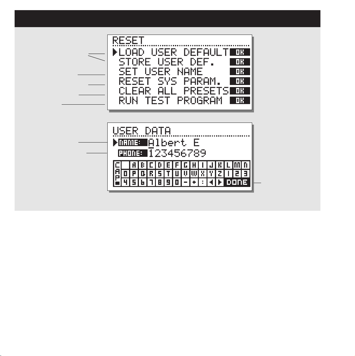
THE RESET PAGE
How to enter the Reset page:
Hold one of the 3 Bypass keys pressed while power-up.
Move the marker using the Cursor keys and press OK
to select the RESET type you desire.
Load User Default
This will reset all system parameters back to a Default setup
made by you (See Store User Def). This reset will NOT delete
the User presets of the M2000.
Store User Def
When you have a perfect setup of your M2000, you are able to
Store this as your own Default setup. This function is very useful,
for example when you have finished a special production and
want to go back to normal. When you have the perfect setup of
your M2000, simply select this parameter and press OK to store
your Default settings.
Set User Name
This function makes it possible to write your Name and Phone
number into the M2000. Press OK to access the User data menu.
Use the ADJUST wheel and the Cursor keys to write your Name
and Phone number into the M2000. Press OK to accept. Your
Name and Phone number will be displayed during power-up.
Reset System Parameters
This will reset all system parameters back to the Factory Default.
This reset will NOT delete the User presets of the M2000.
Reset all Presets
This will Clear all Ram Presets .
Store and load your own
default settings
Enter UserData page
Reset system parameters
Clear all user presets
Test Programs
Type your name here
and your phone number
Place cursor here
and press OK to
finalize session.
Page 31

TECHNICAL SPECIFICATIONS
Digital Inputs and Outputs
Connectors:
Formats:
Output Dither:
Sample Rates:
Processing Delay:
Frequency Response DIO:
Analog Inputs
Connectors:
Impedance:
Max. Input Level:
Min. Input Level (for 0 dBFS):
Sensitivity:
A to D Conversion:
A to D Delay:
Dynamic Range:
THD:
Frequency Response:
Crosstalk:
Analog Outputs
Connectors:
Impedance:
Max. Output Level:
Full Scale Output Range:
D to A Conversion:
D to A Delay:
Dynamic Range:
THD:
Frequency Response:
Crosstalk:
EMC
Complies with:
Safety
Certified to:
Environment
Operating Temperature:
Storage Temperature:
Humidity:
PCMCIA Interface
Connector:
Standards:
Card Format:
Control Interface
MIDI:
GPI, Pedal, Fader:
General
Finish:
LCD:
Dimensions:
Weight:
Mains Voltage:
Power Consumption:
Backup Battery Life:
Warranty Parts and labor:
XLR (AES/EBU), RCA Phono (S/PDIF)
AES/EBU (24 bit), S/PDIF (20 bit), EIAJ CP-340, IEC 958
HPF TPDF dither 8 to 24 bit
44.1 kHz, 48 kHz
0.2 ms @ 48 kHz
20Hz to 23,9 kHz ± 0,01 dB @ 48 kHz
XLR balanced (pin 2 hot)
20 kohm
+22 dBu (balanced)
-10 dBu
@ 12 dB headroom: -22 dBu to +10 dBu
24 bit (1 bit, 128 times oversampling)
0.8 ms @ 48 kHz
>103 dB (unweighted), >106 dB(A)
-95 dB (0,0018 %) @ 1 kHz, -6 dBFS (FS @ +16 dBu)
10 Hz to 20 kHz: +0/-0.2 dB
<-80 dB, 10 Hz to 20 kHz, typical -100 dB @ 1 kHz
XLR balanced (pin 2 hot)
100 ohm (active transformer)
+22 dBu (balanced)
-10 dBu to +22 dBu
24 bit (1 bit, 128 times oversampling)
0.57 ms @ 48 kHz
>100 dB (unweighted), >104 dB(A)
-86 dB (0.005 %) @ 1 kHz, -6 dBFS (FS @ +16 dBu)
10 Hz to 20 kHz: +0/-0.5 dB
<-60 dB, 10 Hz to 20 kHz, typical -90 dB @ 1 kHz
EN 55103-1 and EN 55103-2 FCC part 15, Class B. CISPR 22, Class B
IEC 65, EN 60065, UL 1419, CSA E65
32° F to 122° F (0° C to 50° C)
-22° F to 167° F (-30° C to 70° C)
Max. 90 % non-condensing
PC Card, 68 pin type 1 cards
PCMCIA 2.0, JEIDA 4.0
Supports up to 2 MB SRAM
In/Out/Thru: 5 Pin DIN
1/4” phone jack, 0 ohm to 50 kohm
Anodized aluminum front, Plated and painted steel chassis
56 x 128 dot graphic LCD-display
19" x 1.75" x 8.2" (483 x 44 x 208 mm)
5.2 lb. (2.35 kg)
100 to 240 VAC, 50 to 60 Hz (auto-select)
<20 W
>10 years
1 year
31
Page 32

32
TROUBLESHOOTING
You press the POWER switch but there is no light.
- The power switch on the rear panel is switched off.
The input PPM meters don’t peak out.
- You are using analog inputs, but the input selector in the I/O menu is set to digital in.
- The analog input level is set too low.
Only left input PPM meter is showing a signal.
- Set input selector (in I/O menu) to Both
No sound through the M2000.
- You are using analog inputs, but the input selector in the I/O menu is set to digital in.
You can’t turn the power off.
- Hold the power switch pressed for at least 3 seconds.
All Program sounds »phased«
- You are using the M2000 in combination with a mixing console (send/return), but have not set Mix to 100%. You can do this permanently
in the I/O menu.
Pedal works wrong
- Be sure the pedal is a »make« type.
Page 33

33
MIDI IMPLEMENTATION CHART
STUDIO EFFECTS PROCESSOR M2000 - FEB 2, 1996 Version 1.0
Function Transmitted Recognized Remarks
Basic Channel Default 1-3 1-3 Eng1: 1, Eng2: 2, Com: 3
Changed 1-16 1-16
Mode Default
Messages X X
Altered
Note Number XX
True Voice X X
Velocity Note ON X X
Note OFF X X
After Touch Key’s X X
Ch’s X X
Pitch Bend XX
Control Change from 10 and up from 10 and up Cntl.#10: Mix (If available)
Cntl.#11: Output Level
Cntl.#12: First Param. on Edit page.
Cntl.#13: Second Param. on Edit page.
Cntl.#14: Third ....
Cntl.#15: ...
Cntl.#16: ...
Cntl.#17: ...
All Controllers are single byte type,
scaled to parameter range.
Prog Change OO
True# 0-127 0-127
System Exclusive OO
Common :Song Pos X X
:Song Sel X X
:Tune X X
System real time :Clock O O
:Commands X X
Aux Messages :Local ON/OFF X X
:All Notes OFF X X
:Active Sense X X
:Reset X X
Notes
O:YES Mode1: OMNI ON, POLY Mode 2: OMNI ON, MONO
X:NO Mode 3: OMNI OFF, POLY Mode 4: OMNI OFF, MONO
Page 34

34
SELF TEST
PRESS ONE OF THE 3 BYPASS KEYS, WHILE POWERING UP, TO ACCESS THE SELF-TEST AND SELECT
»RUN TEST PROGRAM«
Turn the Adjust Wheel to scroll through Self tests
Key test
Select Key test by pressing OK.
The keys must be pressed in the order they are requested by the
M2000 to pass the test.
Press Cancel to exit Key test.
Adjust Wheel test
Select Adjust Wheel test by pressing OK
Turn the Adjust Wheel to 30 and back to 0 to pass test.
Press Cancel to exit Adjust Wheel test.
Led test
Select Led test by pressing OK
Turn Adjust Wheel to test the Leds. The test is “ok” when all
Leds are lit.
Press Cancel to exit Led test.
Display test
Select Display test by pressing OK
Press OK to check that all pixels are lit. Press any key to leave
the pixel test.
Press Cancel to exit Display test.
Analog I/O test
Select Analog I/O test by pressing OK
Connect an Analog Output to the Analog Input, which has to be
tested and press OK.
Use a balanced cable.
PPM must show -12 dB to pass test.
Press Cancel to Exit Analog I/O test
Digital I/O test
Select Digital I/O test by pressing OK
Connect a Digital Output to the Digital Input, which has to be
tested and press OK.
The AES/EBU output can also be connected to the S/PDIF input
and vice versa.
PPM must show 0 dB to pass test.
Press Cancel to exit Digital I/O test.
Midi I/O test
Select Midi I/O test by pressing OK
Connect Midi Out to Midi In.
Prg change 1-128 is send out on Midi Thru. Connect this socket
to a Midi compatible device and confirm the Prg. changes.
Press Cancel to exit Midi I/O test.
Pedal test
Select Pedal test by pressing OK.
Connect a momentary pedal to the Pedal socket.
When pressing the Pedal, the Result should be OK.
When released, the Result should be Not OK.
Press Cancel to Exit Pedal test.
PCMCIA test
Select PCMCIA test by pressing OK
Insert PCMCIA card. Note that all Data on PCMCIA card will be
destroyed.
Press OK to test.
Result reads:
Low battery - Time to change battery in your PCMCIA card.
Not Ok - Try the test using another PCMCIA card.
Press Cancel to Exit PCMCIA test.
Battery test
Select Battery test by pressing OK
Confirm that Result is “ok”.
Press Cancel to Exit Battery test.
System test
Select System test by pressing OK
Confirm that Result is “ok”.
Result reads:
Eeprom Not ok - The unit will most likely work ok, the message
is for service matters only.
DSP Not ok - Contact your local dealer.
Press Cancel to Exit System test.
Power Off - On to start standard software.
Page 35

35
GLOSSARY
AES/EBU
Professional digital in/out standard, using balanced XLR cables.
S/PDIF
Consumer digital in/out standard, normally using coaxial phonotype cables.
DITHERING
Dithering is a method to optimize the quality of a digital audio
signal at low levels. A small amount of filtered noise is added to
the signal, giving you a less distorted low level signal.
If you are using digital outputs, the equipment you feed determines the number of bits. A DAT recorder should always be
dithered to 16 bit.
PROF/CONS LEVELS
Depending on which equipment you are using along with the
M2000, you must set the PRO/CON parameters correctly in the
I/O setup menu.
M2000 Analog Inputs:
Consumer range: -16dB to +10dB, nominal level = -10dB
Professional range: -6dB to +16dB, nominal level = +4dB
M2000 Analog Outputs:
Consumer range: -10dB to +16dB
Professional range: -16dB to +6dB
The levels are either listed in the technical specifications or
printed on the rear panel of the connected devices.
DE’ESSING
An algorithm that removes unwanted »esses« from a vocal material.
SYSTEM EXCLUSIVE MIDI COMMANDS
Device-dependent MIDI commands, normally used for remote
controlling machines.
Page 36

36
PRESET LIST - SINGLE PRESETS
1
2
3
4
5
6
7
8
9
10
11
12
13
14
15
16
17
18
19
20
21
22
23
24
25
26
27
28
29
30
31
32
33
34
35
36
37
38
39
40
41
42
43
44
45
46
47
M2000 Hall
Great Vocal Hall
Very Big Hall
Warm MidSize Hall
Bright MidSize Hall
Small Hall
Nice Hall
Realistic Hall
Chorus Reverb
Synthesizer Reverb
Soundcheck Empty Arena
High School gym
Empty Theater
Airport Gate
Big Church
Arvo Part Cathedral
Taj Mahal
Big Snare Hall
Vintage Hall
Wood Floor
Stone Wall
Doubling Room
SlapBack Room
Sidewall Reflections
Backwall Reflections
True Room
Home Room
The Shop
The CORE Room
At Home
New Booth
Large Room
Medium Room
Small Room
Very Small Room
Small Wood Room
Small damped Room
Empty Room
Small Chamber
Very Small Chamber
Dark Chamber
Locker Room
Auditorium
Basement
Empty Garage
In the Bathroom
Classroom
48
49
50
51
52
53
54
55
56
57
58
59
60
61
62
63
64
65
66
67
68
69
70
71
72
73
74
75
76
77
78
79
80
81
82
83
84
85
86
87
88
89
90
91
92
93
94
Tiled Room
Small Room for Drums
Percussion Room
Long Gold Plate
Medium Gold Plate
Short Gold Plate
Large Bright Plate
Snare Plate
Vocal dry
Vocal Wet
Air
Microphone Bleed
Small Studio Room
Small Box Ambience
Tiled Staircase
Nextdoor
Living Room
Phonebooth
Inside a Locker
Inside a Van
Tunnel
ZigZag Perc effect
Triple slap Reverb
Gated Reverb Short
Gated Reverb Medium
Gated Reverb Long
Gated Hall
Gated Room
Gated Gold Plate
Straight Delay
Soft Delay
Slapback Delay
The King Vocal Delay
Delay Doubler Effect
Old Tape Echo
Metallic Delay
In a Tin Can
Plain Chorus
Center Chorus
Chorus Extreme
Stereo Flange
Talking Flange
Dark Flanger
Phaser 1
Phaser 2
Phaser 3
Vocal Compressor
95
96
97
98
99
100
101
102
103
104
105
106
107
108
109
110
111
112
113
114
115
116
117
118
119
120
121
122
123
124
125
126
127
128
Guitar Compressor
Light Compressor
Heavy Compressor
Gain Maximizer
Pumpin Compressor
Heavy Limit
Limiter
Fast Gate
Slow Gate
Expander
Program De-Esser
Vocal De-Essing
Hard De-Essing
Neutral EQ
Bass EQ
Acoustic Guitar EQ
Loudness
Turn up the Bass
Air EQ
Telephone Voice
Voice Multipitch
6-Voice Bass Pitch
6-Voice Guitar Pitch
Fifths Up and Down
Barbershop
Mono to Stereo
Expanded Mono
Casual Panner
Straight Slow Panner
Fast Narrow Panner
Slow Tremolo
Fast Tremolo
Very Fast Tremolo
No Effect
Page 37

37
PRESET LIST - COMBINED PRESETS
1
2
3
4
5
6
7
8
9
10
11
12
13
14
15
16
17
18
19
20
21
22
23
24
25
26
27
28
29
30
31
32
33
34
35
36
37
38
39
40
41
42
43
44
45
46
47
Two 2000 Halls
Deep Room
Smooth Hall
Small warm Hall
Giant Hall
Thick Drum Room
Thick Gated Reverb
Big Drum Hall
Two Verbs
Warm and Slow
Short + Slow Reverb
Big and Warm Hall
Nice Big Hall
Reverb along Reverb
Chorus-like Hall
Warm Vintage Hall
Fat Hall
Flanged Hall
Chorused Hall
Chorused Stonewall
Big Lead Guitar
Reverb + MultiPitch
Realistic Room
Reverb in Reverb
Biig Room
Short Room
Light Medium Room
Double Room
Flanged Small Room
Flanged Ambience
Flanged Room
Open up the Vocal
All Ambience
Far Away
Chorused Room
Sing in the Shower
Nice wide Vocal
Wide Room
Chorused Ambience
Room Multiplied
A litle to the Right
Wobbly Hall
Multiplex Hall
Chorus Doubler
Ultimative Chorus
Unchained Flanger
The King
48
49
50
51
52
53
54
55
56
57
58
59
60
61
62
63
64
65
66
67
68
69
70
71
72
73
74
75
76
77
78
79
80
81
82
83
84
85
86
87
88
89
90
91
92
93
94
Slapdelay along Hall
Slapdelay + Gateverb
Room + Long Delay
Very Long Delay-Verb
Right and Left
Subtle Slap
Clean Arpegio
Tap Dance Delay
Fast Flanged Delay
Nice Pitch + Delay
Bright Delay
Two Delays
Thick Delay
Telephone Delay
Slpabacking Flanger
Slapback and Doubler
Chorus + Delay
Beautiful SpaceDelay
Slow Reverb + Delay
Echo Chorus
Slowflange and Echos
Fizzy Echoes
Compressed Flanger
Comp + Gated Verb
Comp+ Small Drumhall
Compressed Snarehall
Compressed Room
Compressed + Hall
Vocal Comb + Delay
De-essed Delay
De-Essed M2000 Hall
De-Essed Bright Hall
De-Essed Basement
De-Essed Ambience
Heavy Limit+Expander
De-Esser + EQ
Compressor+De-esser
Limiter + EQ
Compressor + Expand
Compressor + Limiter
Vocal Compressor+EQ
LeslieLike Rotor
Panned Delay
Slow Panned Phone
Moving Ambience
Moving Vintage Hall
Autopanned Stonewall
95
96
97
98
99
100
101
102
103
104
105
106
107
108
109
110
111
112
113
114
115
116
117
118
119
120
121
122
123
124
125
126
127
128
Slapdelay in Circles
Doubler and Panner
Panned Inverse
Slow Moving Reverb
In Cirkles
Two Panners
True Stereo Delay
Stereo Garage
Stereo EQ
Stereo Compressor
Stereo Limiter
Stereo Gate
Short Stereo Delay
True Stereo Reverb
Insert Compressors
Insert EQs
Insert Gates
Echo in the Basement
Dynamic Flanger
Vocalroom-Choruslike
Short-Long Reverb
Compressor-Reverb
Bright -Warm Reverb
Warm-Bright Reverb
Chorus-Chorus
Dynmorph Looong Room
Hall-Ambience
Slapdelay-Vocal Wet
Delay-SlapDelay
Dynmorph SneakingVerb
Delay-Reverb
Reverb-Delay
Changing Ambience
Blues in a Room
 Loading...