


StorageLoaderTM
INSTALLATION AND USER MANUAL
TANDBERG DATA ASA |
|
|
P.O. Box 134 Kjelsås |
|
|
N-0411 OSLO, NORWAY |
|
|
Phone + 47 22 18 90 90 |
|
|
Telefax + 47 22 18 95 50 |
|
|
www.tandberg.com |
Part No. |
433061-04 |
|
||
© Tandberg Data ASA |
May |
2006 |

Related publications available from Tandberg Data ASA:
|
Part No. |
|
Title |
|
|
|
|
|
|
432980 Tandberg Data StorageLoader SCSI Interface Functional
Specifications.
433060 Tandberg Data StorageLoader Quick Installation Guide
This publication may describe designs for which patents are granted or pending. By publishing this information, Tandberg Data ASA conveys no license under any patent or any other rights.
Every effort has been made to avoid errors in text and diagrams. However, Tandberg Data ASA assumes no responsibility for any errors, which may appear in this publication.
It is the policy of Tandberg Data ASA to improve products as new techniques and components become available. Tandberg Data ASA therefore reserves the right to change specifications at any time.
We would appreciate any comments on this publication.

Table of Contents |
|
|
1. About This Manual...................................................... |
5 |
|
2. General Information................................................... |
7 |
|
2.1 |
Models .............................................................. |
8 |
|
2.1.1 Capacity ................................................... |
8 |
|
2.1.2 Data Transfer Rates.................................... |
8 |
2.2 |
Product Description............................................. |
8 |
|
2.2.1 Front Panel................................................ |
9 |
|
2.2.2 Internal Components ................................. |
11 |
|
2.2.3 Rear Panel ............................................... |
13 |
3. Installation .............................................................. |
14 |
|
3.1 |
Performing the Installation ................................. |
14 |
4. Operation and Configuration .................................... |
26 |
|
4.1 |
System PowerOn.............................................. |
26 |
4.2 |
Front Panel Display Modes .................................. |
29 |
|
4.2.1 Menus ..................................................... |
29 |
|
4.2.2 Dialogs .................................................... |
31 |
|
4.2.3 Messages ................................................. |
33 |
|
4.2.4 Status and Information .............................. |
33 |
4.3 |
Main Menu........................................................ |
34 |
4.4 |
Setup Menu ...................................................... |
35 |
|
4.4.1 StorageLoader setup.................................. |
35 |
|
4.4.2 SCSI Setup .............................................. |
36 |
|
4.4.3 Remote Management setup ........................ |
36 |
4.5 |
View Data Menu ................................................ |
37 |
|
4.5.1 StorageLoader Info.................................... |
37 |
|
4.5.2 Drive Info ................................................ |
38 |
|
4.5.3 Remote Management Info .......................... |
39 |
|
4.5.4 Statistics.................................................. |
39 |
4.6 |
Utilities Menu.................................................... |
39 |
|
4.6.1 The Maintenance Menus ............................. |
40 |
|
4.6.2 The Diagnostics Menu ................................ |
40 |
|
4.6.3 Set Password............................................ |
41 |
4.7 |
Cartridge Handling............................................. |
41 |
|
4.7.1 Cartridge Slot Numbers.............................. |
41 |
|
4.7.2 Moving Cartridges to and from the Drive ...... |
41 |
4.8 |
Magazine Handling ............................................ |
42 |
|
4.8.1 Removing the Magazine from the Unit .......... |
42 |
|
4.8.2 Inserting Cartridges into the Magazine ......... |
44 |
|
4.8.3 Removing Cartridges from the Magazine....... |
44 |
|
4.8.4 Inserting a Magazine into the Unit ............... |
45 |
|
4.8.5 Manual/Emergency Release of Magazines ..... |
46 |
4.9 |
Standby Functionality ........................................ |
46 |
5. Remote Management ............................................... |
48 |
|
StorageLoader Installation and User Manual |
1 |
|

Tandberg Data |
|
About This Manual |
|
5.1 |
Remote management configuration...................... |
48 |
|
|
5.1.1 Quick start guide....................................... |
48 |
|
|
5.1.2 Enabling the RMI without rebooting ............. |
48 |
|
5.2 |
Remote management web pages ......................... |
49 |
|
|
5.2.1 Information Boxes..................................... |
49 |
|
|
5.2.2 StorageLoader Start Page........................... |
50 |
|
|
5.2.3 Status Page.............................................. |
51 |
|
|
5.2.4 Settings Pages .......................................... |
53 |
|
|
5.2.5 Command Page......................................... |
54 |
|
|
5.2.6 Maintenance Pages .................................... |
54 |
|
6. Maintenance............................................................. |
55 |
||
6.1 |
Using the Cleaning Cartridge............................... |
55 |
|
|
6.1.1 Running an Installed Cleaning Cartridge ....... |
55 |
|
|
6.1.2 Removing the Cleaning Cartridge ................ |
56 |
|
6.2 |
Installing Firmware Upgrades .............................. |
57 |
|
|
6.2.1 Firmware Upgrade via SCSI ........................ |
57 |
|
|
6.2.2 Possible Upgrade Problems ......................... |
58 |
|
6.3 |
Embedded Diagnostics ....................................... |
58 |
|
6.4 |
Reinstalling the Transport Lock............................ |
58 |
|
|
6.4.1 Transport Lock Installation Procedure........... |
59 |
|
6.5 |
Field Replaceable Units (FRUs) ............................ |
59 |
|
|
6.5.1 FRU Drive Tray Assy DLT VS160 SCSI .......... |
60 |
|
|
6.5.2 FRU Drive Tray Assy 420LTO....................... |
63 |
|
|
6.5.3 FRU Power Supply ..................................... |
65 |
|
|
6.5.4 FRU Fan................................................... |
66 |
|
|
6.5.5 FRU Magazine ........................................... |
68 |
|
|
6.5.6 FRU Filter................................................. |
69 |
|
7. Troubleshooting ....................................................... |
71 |
||
7.1 |
How to Take Memory Dumps of the Loader ........... |
71 |
|
7.2 |
How to Take Memory Dumps of the Drive ............. |
71 |
|
7.3 |
Hardware checking ............................................ |
71 |
|
7.4 |
Software checking ............................................. |
72 |
|
7.5 |
Verifying Recent Changes ................................... |
72 |
|
7.6 |
Trouble shooting matrix ..................................... |
73 |
|
7.7 |
The Error Screen .............................................. |
80 |
|
7.8 |
Error Codes ...................................................... |
82 |
|
Appendix A |
– Specifications ....................................... |
85 |
|
A.1 Mechanical Dimensions and Weight...................... |
85 |
||
A.2 |
Power Requirements .......................................... |
86 |
|
A.3 |
Vibration Specifications ...................................... |
89 |
|
A.4 |
Mechanical Shock Specifications .......................... |
90 |
|
A.5 |
Drop |
................................................................ |
90 |
A.6 |
Climatic Specifications........................................ |
90 |
|
A.7 |
Noise Specification ............................................ |
91 |
|
A.8 |
Product Reliability.............................................. |
91 |
|
Appendix B |
– Spare parts/Accessories ....................... |
91 |
|
2 |
StorageLoader Installation and User Manual |

Tandberg Data |
Remote Management |
|
Table of Figures |
|
|
Figure 2.1 Overview of Tandberg Data StorageLoader 1U ... |
7 |
|
Table 2- 1 |
Data Storage Capacity ................................ |
8 |
Table 2- 2 |
Data Transfer Rates .................................... |
8 |
Figure 2.2 Front panel of the StorageLoader ..................... |
9 |
|
Figure 2.3 Internal components of the StorageLoader ...... |
11 |
|
Figure 2.4 Cartridge magazines..................................... |
12 |
|
Figure 2.5 Rear panel of the StorageLoader .................... |
13 |
|
Figure 3.1 Rack Mounting kit ........................................ |
16 |
|
Figure 3.2 Rack mount rail ........................................... |
17 |
|
Figure 3.3 Mounting the Rack mounting kit to a rack........ |
18 |
|
Figure 3.4 Rack mounting kit mounted in rack ................ |
18 |
|
Figure 3.5 Slide the StorageLoader in from the front ........ |
19 |
|
Figure 3.6 Fasten the front of the StorageLoader to the rack19 |
||
Figure 3.7 Fasten the rear of the StorageLoader to the rails.19 |
||
Figure 3.8 Main Power switch, fuse holder and power cord |
|
|
connection............................................................ |
20 |
|
Figure 3.9 Robotics lock marked with red plastic tab ........ |
21 |
|
Figure 3.10 SCSI cable and SCSI terminator connection ... |
23 |
|
Figure 3.11 Positioning of bar code label for LTO cartridges.24 |
||
Figure 3.12 Positioning of bar code label for DLT cartridges.25 |
||
Figure 4.1 Poweron Screen ......................................... |
26 |
|
Figure 4.2 Snapshot while running Inventory .................. |
26 |
|
Figure 4.3 The Default screen ....................................... |
27 |
|
Table 4- 1 Robot Operation Statuses .............................. |
27 |
|
Table 4- 2 Drive Operation Statuses ............................... |
28 |
|
Figure 4.4 Standard Menu Layout.................................. |
29 |
|
Figure 4.5 The Complete Menu Tree .............................. |
30 |
|
Figure 4.6 Standard Dialog Layout................................. |
31 |
|
Figure 4.7 Dialog layout, entering discrete values ............ |
31 |
|
Figure 4.8 Slot dialog layout. ........................................ |
32 |
|
Figure 4.9 Predefined options, showed one at the time..... |
32 |
|
Figure 4.10 A default screen. ........................................ |
33 |
|
Figure 4.11 Load to Drive............................................. |
41 |
|
Figure 4.12 Load to Drive............................................. |
42 |
|
Figure 4.13 Empty Drive Message ................................. |
42 |
|
Figure 4.14 Removing magazine ................................... |
43 |
|
Figure 4.15 Magazine eject........................................... |
43 |
|
Figure 4.16 Removing the magazine from the loader........ |
44 |
|
Figure 4.17 Gently push the cartridge into the magazine slot44 |
||
Figure 4.18 Push the release knob towards the cartridge to eject |
||
.......................................................................... |
|
45 |
Figure 4.19 Cartridge position after manual release from magazine |
||
slot...................................................................... |
|
45 |
Figure 4.20 Push magazine until it clicks into place .......... |
45 |
|
Figure 4.21 Pointing out hole used to insert release tool ... |
46 |
|
Figure 4.22 Magazine release tool in use ........................ |
46 |
|
Figure 5.1 Navigation Menu .......................................... |
49 |
|
Figure 5.2 Remote Management Start Page .................... |
51 |
|
Tandberg Data |
|
About This Manual |
|
Figure 5.3 Remote Management Status Page .................. |
52 |
|
|
Figure 5.4 Remote Management Command Page ............. |
54 |
|
|
Figure 6.1 Transport lock marked with red plastic tab |
..... 58 |
|
|
Figure 6.2 Field Replaceable Units ................................. |
60 |
|
|
Figure 6.3 Replacing the tape drive ............................... |
61 |
|
|
Figure 6.4 Rear of the tape drive................................... |
61 |
|
|
Figure 6.5 |
Releasing the tape drive .............................. |
61 |
|
Figure 6.6 Guide cartridge mounting.............................. |
62 |
|
|
Figure 6.7 Correct position of Guide cartridge mounting ... 62 |
|||
Figure 6.8 Replacing the tape drive ............................... |
63 |
|
|
Figure 6.9 Rear of the tape drive................................... |
64 |
|
|
Figure 6.10 Releasing the tape drive.............................. |
64 |
|
|
Figure 6.11 Exchanging a defective power supply ............ |
65 |
|
|
Figure 6.12 Removing the fixing screw........................... |
65 |
|
|
Figure 6.13 Fan power................................................. |
66 |
|
|
Figure 6.14 Removing the back panel cover plate ............ |
66 |
|
|
Figure 6.15 Removing the fan....................................... |
67 |
|
|
Figure 6.16 Notch in chassis for fan cable....................... |
67 |
|
|
Figure 6.17 Replacing dust filter.................................... |
69 |
|
|
Figure 7.1 Error Code Page........................................... |
80 |
|
|
Figure 7.2 Example of detailed information ..................... |
81 |
|
|
Figure 7.3 Example of further detailed information .......... |
81 |
|
|
Figure 7.4 Example of action ........................................ |
81 |
|
|
Figure 7.5 Warning message concerning reboot .............. |
81 |
|
|
Table A - 1 StorageLoader Mechanical Dimensions and Weight |
|||
|
85 |
|
|
Table A - 2 StorageLoader Power Requirements ............ |
86 |
|
|
Table A - 3 StorageLoader sine sweep levels ................ |
89 |
|
|
Table A - 4 StorageLoader random vibration levels ........ |
89 |
|
|
Table A - 5 StorageLoader mechanical shock levels ....... |
90 |
|
|
Table A - 6 StorageLoader drop test ............................ |
90 |
|
|
Table A - 7 StorageLoader temperature specification |
..... 90 |
|
|
Table A - 8 StorageLoader humidity specification .......... |
91 |
|
|
Table A - 9 StorageLoader altitude specification ........... |
91 |
|
|
Table A - 10 StorageLoader noise specification............ |
91 |
|
|
Table B - 1 List of spare parts and accessories .............. |
92 |
|
|
Table of Tables |
|
|
|
Table 2- 1 Data Storage Capacity ..................................... |
8 |
|
|
Table 2- 2 Data Transfer Rates ........................................ |
8 |
|
|
Table 4- 1 Robot Operation Status ................................. |
27 |
|
|
Table 4- 2 Drive Operation Status .................................. |
28 |
|
|
Table A- 1 |
StorageLoader Mechanical Dimensions and Weight |
||
|
85 |
|
|
Table A- 2 |
StorageLoader Power Requirements ............ |
86 |
|
Table A- 3 |
StorageLoader sine sweep levels ................ |
89 |
|
Table A- 4 |
StorageLoader random vibration levels ........ |
89 |
|
Table A- 5 |
StorageLoader mechanical shock levels ....... |
90 |
|
4 |
StorageLoader Installation and User Manual |

Tandberg Data |
|
Remote Management |
|
Table A- 6 |
StorageLoader drop test ............................ |
|
90 |
Table A- 7 |
StorageLoader temperature specification ..... |
90 |
|
Table A- 8 |
StorageLoader humidity specification .......... |
91 |
|
Table A- 9 |
StorageLoader altitude specification ............ |
91 |
|
Table A- 10 |
StorageLoader noise specification ............... |
|
91 |
Table B- 1 |
List of spare parts and accessories .............. |
|
92 |
1. About This Manual |
|
|
|
This m anual describes how to install and use the Tandberg Data |
|||
StorageLoader for 420LTO and DLT VS160 |
tape drives. I t is |
||
intended for |
use by anyone who would install, |
use and |
m aintain |
the device. |
|
|
|
Chapter 2:General I nform at ion gives a product description of the StorageLoader.
Chapter 3:Installation describes how to install the device.
Chapter 4:Operat ing and Configurat ion describes how to use the local interface, how to configures the device, and how to handle the cartridges and magazines.
Chapter 5:Rem ot e Managem ent describes the functionality of the Remote Management via the Ethernet.
Chapter 6:Maintenance describes cleaning and upgrading procedures, and how to prepare the StorageLoader for shipping.
Chapter 7:Troubleshooting lists possible areas to investigate if you are having problems with the StorageLoader.
AppendixA: Specifications lists the specification data for the Tandberg Data StorageLoader 1U.
Appendix B: Spare part s and Accessories lists all accessories and spare parts with part number.

2. General Information
Tandberg |
Data |
StorageLoaderTM is |
a com pact tape cartridge |
loader designed |
for secure, reliable, unattended system backup. |
||
The loader |
can |
be m ounted in a 19” |
rack or used as a tabletop |
unit. Its height is 1U. |
|
||
The loader is equipped with a Tandberg DLT VS160, 220LTO or 420LTO tape drive and has room for 8 cartridges in two 4- cartridge magazines.
Figure 2.1 Overview of Tandberg Data StorageLoader 1U
The entire system is under host control via an industrystandard SCSI interface. I ts robotic tape handling is both rugged and sim ple for utmost reliability
The key features of the StorageLoader include:
Two rem ovable cartridge m agazines, each with space for four cartridges
Integrated Bar Code Reader (Optional on some models)
Magazine release under system control
Low Voltage Differential ( LVD) / SingleEnded ( SE) SCSI
Interface
Onboard Diagnostics
Remote management
Operators interface with front panel display and four control buttons
Standby functionality
Replaceable dust filters
Tape drive, m agazines, power supply and fans are Field Replaceable Units (FRUs)
StorageLoader Installation and User Manual |
7 |

Tandberg Data |
Operation and Configuration |
|
|
|
|
*** IMPORTANT ***
Review the READ ME FIRST caution at the beginning of
Chapter. 3 before you power up the unit for the first time.
Models.For additional specification inform ation for this model, refer to Appendix A.
2.1.1 Capacity
|
StorageLoader Model |
|
|
Cartridge |
Cartridge |
Magazine |
Magazine |
|
|
|
|
|
|
Capacity |
Capacity |
Capacity |
Capacity |
|
|
|
|
|
(Native) |
(Comp 2:1) |
(Native) |
(Comp 2:1) |
|
|
|
|
|
|
|
|
|
|
Tandberg |
|
|
|
100GB |
200GB |
800 GB |
1.6TB |
|
StorageLoader LTO1 |
|
|
|
|
|
||
|
|
|
|
|
|
|
|
|
|
Tandberg |
|
|
|
200GB |
400GB |
1.6TB |
3.2TB |
|
StorageLoader LTO2 |
|
|
|
|
|
||
|
|
|
|
|
|
|
|
|
|
Tandberg |
|
|
|
80GB |
160GB |
640GB |
1.28TB |
|
StorageLoader VS160 |
|
|
|
|
|
||
|
|
|
|
|
|
|
|
|
Table 2-1 |
Data Storage Capacity |
|
|
|
||||
2.1.2 Data Transfer Rates
|
StorageLoader Model |
|
|
Maximum Sustained |
Maximum Sustained |
|
|
|
|
|
|
Rate, Native |
Rate, Compressed |
|
|
|
|
|
|
|
|
Tandberg |
|
|
|
16MB/s |
32MB/s |
|
StorageLoader LTO1 |
|
57.6GB/hr |
115.2GB/hr |
||
|
|
|
|
|
|
|
|
Tandberg |
|
|
|
24MB/s |
48MB/s |
|
StorageLoader LTO2 |
|
86.4GB/hr |
172.8GB/hr |
||
|
|
|
|
|
|
|
|
Tandberg |
|
|
|
8MB/s |
16MB/s |
|
StorageLoader VS160 |
|
28.8GB/hr |
57.6GB/hr |
||
|
|
|
|
|
|
|
Table 2-2 |
Data Transfer Rates |
|
||||
2.2 Product Description
The StorageLoader has several features designed to increase the ease of use and utility of the product, such as:
Two rem ovable m agazines allow for easy m anagem ent of data sets or archival storage. For the StorageLoader each magazine has room for four cartridges.
A m enudriven operator |
control panel interface with backlit |
LCD provides easy control for configuration and diagnostic |
|
activities. |
|
8 |
StorageLoader Installation and User Manual |
Tandberg Data |
|
|
|
|
|
|
|
|
Operation and Configuration |
|||||
An Ethernet |
connection |
allows |
for m anagem ent by an |
|
||||||||||
operator |
with |
|
a |
standard |
web |
|
browser |
on |
a |
rem ote |
||||
com puter. |
The |
rem ote |
operator |
can |
do |
m ost |
of |
the |
||||||
operations that can be done through the front panel, such as |
||||||||||||||
m onitoring the |
loader’s |
status and |
downloading |
statistical |
||||||||||
and diagnostic information. |
|
|
|
|
|
|
|
|
|
|||||
For inform ation |
on |
the |
installed |
tape |
drive; |
see |
the |
tape |
drive |
|||||
manuals referred to in chapter 1. |
|
|
|
|
|
|
|
|
|
|||||
2.2.1 Front Panel
The Front Panel includes the User Control Panel with LCD display, four Control Buttons, two LED indicators and a Standby switch. The bezels of the two magazines are also visible from the front.
Magazine |
LED |
Standby |
LCD |
Control |
Magazine |
front bezel |
indicators |
switch |
display |
buttons |
front |
|
|
|
|
|
bezel |
Figure 2.2 Front panel of the StorageLoader
LCD – liquid crystal display
The display is a backlit 122 x 32, dot - m atrix graphical display that can show four lines of 20 characters.
I n various m odes of operation, the display panel screens and control buttons allow you to do the following:
Enter settings for StorageLoader configuration
Issue operational commands
View StorageLoader status and information
Test StorageLoader functionality
Control Buttons
The labels for the four control buttons are displayed in the corners of the LCD. All buttons have “soft labeling” for different m odes of operation ( i.e., the functions and labels of the buttons change during different activities) . The actual soft label for each button for
StorageLoader Installation and User Manual |
9 |

Tandberg Data |
Operation and Configuration |
|
|
|
|
any activity is always visible on the display.
LED Indicators
The two LED indicators are green and am ber. They indicate the StorageLoader activity as follows:
Green LED on: The StorageLoader is either running or ready for operation.
Green LED blinking: Short blinks followed by long intervals indicate that the loader is in low power standby mode.
Am ber LED on: Fault LED, the StorageLoader has encountered an electrical or mechanical failure.
Both LED’s off: The StorageLoader is offline. This is the case while the loader is initializing, after poweron, and when a magazine is removed.
Standby Switch
A switch on the front panel provides a Loader Standby. I f the switch is pushed when the loader is active, the loader will complete the current operation and go off line and enter standby m ode, see more details in chapter 4.9, Standby Functionality.
Magazine Front Bezel
The front bezel of the m agazines is visible from the front . All m agazine handling is described in detail in chapter 4.8, Magazine Handling.
10 |
StorageLoader Installation and User Manual |

Tandberg Data Operation and Configuration
Internal Components
The StorageLoader features the m ain internal com ponents shown in the figure below.
|
|
|
Drive |
|
|
Slot 4 |
Power Supply |
|
|
|
|
|
Slot 3 |
Cartridges |
|
|
|
|
|
|
Slot 2 |
|
Slot 8 |
|
Robotics |
|
|
|
|
|
|
Slot 1 |
|
module |
Slot 7 |
|
|
|
|
|
|
Slot 6 |
|
Left magazine
Slot 5
Front panel
Right magazine
Figure 2.3 Internal components of the StorageLoader
Tape Drive
The StorageLoader is equipped with one tape drive, which is located in the centre in the back of the loader. The drive is a field-
replaceable unit ( FRU) |
that can be rem oved/ replaced |
while |
the |
loader is m ounted in a |
rack. See section 6.5.1, FRU |
Drive |
Tray |
Assy DLT VS160 SCSI , section 6.5.2, FRU Drive Tray Assy 220LTO and 420LTO.
Robotics Module |
|
|
|
|
||
The |
robotic |
cartridge |
handling m echanism m oves |
cartridges |
||
between the |
cartridge |
slots in the two m agazines |
and |
the |
tape |
|
drive. |
|
|
|
|
|
|
Barcode Reader |
|
|
|
|
||
The |
barcode |
reader is |
standard and an optional |
part |
on |
som e |
models. When m ounted, it is integrated in the Robotics Module. Please note that StorageLoader specific bar code labels need to be used to achieve correct operation of the bar code reader.
StorageLoader Installation and User Manual |
11 |

Tandberg Data Operation and Configuration
Cartridge Magazines |
|
||
There |
are two |
rem ovable m agazines |
( FRUs) , each holding four |
tape |
cartridges, |
see figure 2.4. The |
m agazine includes design |
features to ensure that cartridges are always inserted correctly and stay securely seated. All magazine handling is described in detail in section 4.8, Magazine Handling.
The Cartridge Slots in the m agazines are num bered as shown in figure 2.3
Figure 2.4 Cartridge magazines
Power Supply
The power supply regulates the electrical power supplied to the device. I t is easily rem ovable ( FRU) for quick field service; see section 6.5.3, FRU Power Supply.
12 |
StorageLoader Installation and User Manual |

Tandberg Data |
Operation and Configuration |
|
|
|
|
2.2.2 Rear Panel
The figure below shows the rear panel of the StorageLoader.
Main |
Fuse |
Power cord Fan |
Back panel |
Fan |
SCSI |
Ethernet |
Power |
|
connection |
cover plate |
|
connectors |
port |
switch |
|
|
|
|
|
|
Figure 2.5 Rear panel of the StorageLoader
Two Integrated Cooling Fans
The rear panel contains two forcedair cooling fans, which draw air inward through the front and expel it out in the back. The fans will start whenever the drive is operating or when the internal tem perature in the StorageLoader gets too high. The cooling fans are field replaceable units, see section 6.5.4, FRU Fan.
Main Power Switch/ Fuse/Power cord connection
The m ain power switch is found on the rear of the loader on the power supply bracket . The power switch, the fuse holder ( with a 250V 2A (H) fuse) and the AC power cord connection are combined in one common unit.
SCSI Interface Connectors
The StorageLoader has two shielded 68pin VHDCI SCSI connectors on the rear panel. The connectors are used for connecting the tape drive and the StorageLoader to a SCSI bus. These connectors can link to the following:
A shielded male VHDCI SCSI cable
A shielded male VHDCI SCSI terminator.
Ethernet Port
This port is for the Rem ote Managem ent system and allows you to connect the StorageLoader to a 10/100 BaseT Ethernet network.
Back Panel Cover Plate
Rem oving the Back Panel Cover Plate gives you access to all the fieldreplaceable units located at the back of the StorageLoader.
StorageLoader Installation and User Manual |
13 |

Tandberg Data |
Operation and Configuration |
|
|
|
|
3. Installation
This chapter provides stepby- step instructions on how to properly prepare and install the Tandberg Data StorageLoader.
READ ME FIRST
CAUTION! !
YOU MUST REMOVE THE
ROBOT TRANSPORT LOCK
WHEN POWERING UP THE UNIT FOR THE FIRST TIME
OR IT WILL NOT OPERATE.
SEE THE PROCEDURE ON THE FOLLOWING PAGES.
3.1 Performing the Installation
To install the StorageLoader, complete the following steps.
Step 1. Unpacking the StorageLoader
Carefully unpack the unit from the shipping container. Save the container and packing m aterials in case you need to transport the StorageLoader in the future. The packaging is specifically designed for the loader to ensure it is not damaged during transportation.
Review the contents of the shipping container to be sure that all parts were included in the shipm ent . A standard package for the StorageLoader consists of the following items:
A factoryassem bled StorageLoader unit containing two cartridge magazines.
A Standard Accessory Kit containing:
-1 The Tandberg Data StorageLoader CD containing all manuals
-1 Printed copy of the Quick Installation Guide
-1 Warranty/Registration Card
-Rack Mount Hardware Kit
14 |
StorageLoader Installation and User Manual |

Tandberg Data |
Operation and Configuration |
|
|
|
|
-2 Line Power Cords: one for USA/ Japan and one for European power outlets
-1 VHDCI SCSI Interface Cable
-1 68pin VHDCI LVD/SE SCSI Terminator.
-1 Ethernet cable
-Tool for Emergency Magazine Release
-30 StorageLoader specific Bar code labels
There will be variations of this list . Please also refer to your Quick I nstallation guide shipped with the StorageLoader.
Note: The StorageLoader contains no cartridges before shipment.
Step 2. Installing the StorageLoader in a Rack
The StorageLoader is designed for use in 19” rack system using 1U of rack space. The length of the power cord and the SCSI cable may restrict the placement.
Attention: The StorageLoader is designed to operate in a horizontal position. Do not attem pt to operate the StorageLoader in any other position than horizontally. Also make sure that:
The airflow around the front and back of the StorageLoader is not obstructed.
There is a minimum of 60cm free space in front of the unit to allow the operator to safely remove the magazines.
The display and operator controls are easily accessed.
The StorageLoader is away from environm ent with tem perature Appendix A.
the floor , and in a clean within specification, see
The Rack Mounting Kit includes the following items:
Rail Left Assembly
Rail Right Assembly
Screw M6x12 (6 pieces)
Screw M5x8 (2 pieces)
Recommended mounting tools:
StorageLoader Installation and User Manual |
15 |
Tandberg Data |
Operation and Configuration |
|
|
|
|
Folding rule or tape measure
Screwdriver
7 mm openend wrench
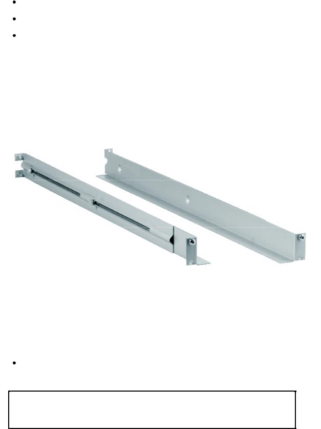
Note: The rails are m ounted to the loader during transportation. Before mounting the rails into the rack, dismount the rails from the loader and remove the spacers between the rails and the loader.
Back
Rail Right Assembly
Rail Left Assembly
Front
Figure 3.1 Rack Mounting kit
Installing the Rack Mounting Kit
Determine the proper position of the rails in the rack.
Caution: Consider rack stability when deciding where to place the StorageLoader, hazardous conditions can be the result of uneven mechanical loading of a rack.
16 |
StorageLoader Installation and User Manual |

Tandberg Data |
Operation and Configuration |
|
|
|
|
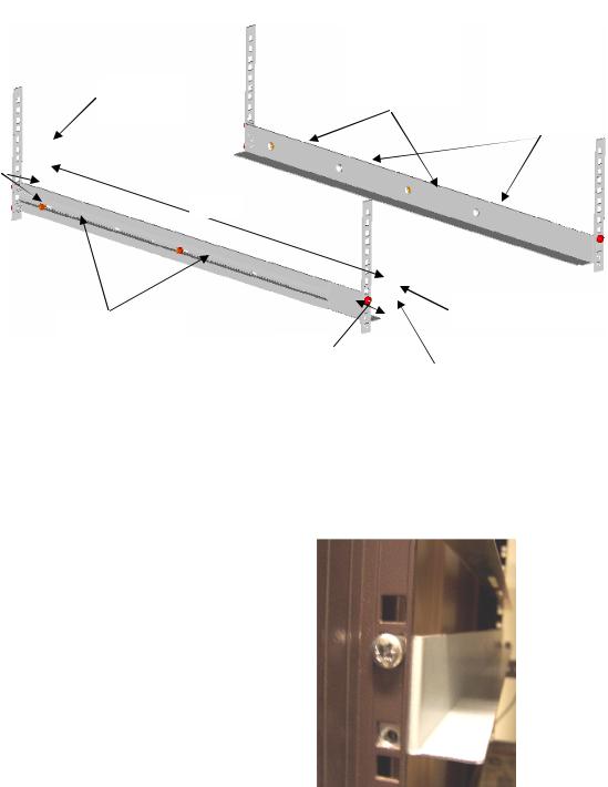
StorageLoader 1U uses 1U of vertical rack space. The rails m ust be installed in a full U position ( The bottom of the rails m ust be aligned with the bottom of a U), see figure 3.2.
|
|
Figure 3.2 Rack mount rail |
|
||
Installing the “Rail Left Assembly” |
|
|
|
||
1. Measure the length between the rear |
rack m ount rails and |
||||
the front |
rack m ount rails. I f the m easurem ent |
is |
shorter |
||
than |
the |
StorageLoader, m ove the |
two sets |
of |
screws |
M4x12, washers and nuts shown in Figure 3.3. |
|
|
|||
2. Adj ust |
the “Rail Left Assem bly” to fit |
the m easurem ent in |
|||
step 1. |
|
|
|
|
|
3. Use a 7 mm openend wrench together with the screwdriver to tighten the two M4x12 screws to fix the rail length.
Note: Using more than two screws will increase the stability of the Rack Mounting Kit.
4. Place the “Rail Left Assem bly” on the left side of the rack, between the rear rack m ount rail and the front rack m ount rail.
5. Mount the “Rail Left Assem bly” at desired height using one M6x12 screw in front (upper hole in rail only) and two M6x12 screws at the backside. See figure 3.4.
Installing the “Rail Right Assembly”
Follow the instruction for left side only using the “Rail Right Assembly” on the right side of the rack.
StorageLoader Installation and User Manual |
17 |
Tandberg Data |
Operation and Configuration |
|
|
|
|
|
Use these holes |
|
|
if rack depth is |
Step 1 |
|
equal or longer |
Holes to be |
|
than the |
used if rack |
Rear Rack |
StorageLoader |
depth is shorter |
|
than the |
|
Mount Rail |
|
|
|
StorageLoader |
|
|
|
Step 5
(Screw
M6x12)
Step 1
Step 3 |
|
Front Rack Mount Rail |
|
|
|
||
(Screw M4x12, |
Step 2 |
Step 5 |
|
nut and washer) |
|||
|
|||
|
|
(Screw M6x12) |
Figure 3.3 Mounting the Rack mounting kit to a rack
Figure 3.4 shows step 5 in the description:
Rack m ounting kit m ounted in rack with one screw M6x12 in upper hole on both left and right side.
On the |
rear |
side |
two |
screws |
m ust be |
used |
on |
both |
left and |
right side. |
|
|
|
|
Totally six screws are used to install the “rack m ounting kit” to the rack.
Figure 3.4 Rack mounting kit mounted in rack
Mounting the StorageLoader to the Rack
Make sure that all the screws in the Rack Mounting Kit are tightened properly before installing the StorageLoader in the rack.
18 |
StorageLoader Installation and User Manual |
Tandberg Data |
Operation and Configuration |
|
|
|
|
Slide the StorageLoader on the rails from the front of the rack, as shown in figure 3.5. Then fix the StorageLoader using one M6x12 screw in front of the rack on both left and right side ( see figure 3.6) and one M5x8 on the backside of the Rack Mounting Kit on both left and right side (see figure 3.7).
Figure 3.5 Slide the StorageLoader in from the front
Figure 3.6 Fasten the front of the StorageLoader to the rack
Use one M5x8 screw on both left and right side (M5-thread) to fasten the StorageLoader to the rails’ backside.
Figure 3.7 Fasten the rear of the StorageLoader to the rails.
How to dismount the StorageLoader from the rack
Make sure that you have disconnected all the cables before you start dismounting the StorageLoader from the rack.
Unscrew the M5x8 screws at the back of the rack m ounting kit . (See figure 3.7)
Unscrew the M6x12 screw at the front of the rack. Note that you only unscrew the lowest screw. (See figures 3.5 and 3.6)
Slide the StorageLoader gently out of the rack. Note that the StorageLoader’s weight is 14.6kg!
StorageLoader Installation and User Manual |
19 |

Tandberg Data |
Operation and Configuration |
|
|
|
|
Step 3. Connecting Power Cable
The StorageLoader is offered both with AC and DC connection.
- DC connection.
This version is offered with special connector and - 48 VDC voltage. This is described in appendix. A2. Please note grounding requirements and special connector.
AC connection
Before connecting the StorageLoader to your host com puter system you should run the selfdiagnostic of the unit . This preparation requires power to the StorageLoader. Go through the following steps to perform this test:
1. Use the power cables from the accessories included in the shipm ent . Make sure you select the power cord suited for your power system.
2. Plug the power cable into the rear of the StorageLoader ( see figure 3.8) . Plug the other end of the cable into a properly grounded electrical outlet.
Note: Reliable eart hing depends on eart hing in t he AC elect rical out let , in which t he St orageLoader’s power cable is connect ed. Adding the StorageLoader to an existing rack installation can cause a leaking current fault condit ion because of t he sum m at ion of t he leaking current s. For securit y, a 250V 2A ( H) fuse is locat ed near the power switch.
3. Turn on the StorageLoader
by |
switching |
the |
Power |
||
Switch |
|
to |
“1” . |
||
I f |
the |
transport |
lock |
is |
|
present |
the |
loader |
will |
||
detect |
this |
and |
instruct |
||
the user to rem ove it, see next step.
Figure 3.8 Main Power switch, fuse holder and power cord connection
20 |
StorageLoader Installation and User Manual |

Tandberg Data Operation and Configuration
Step 4. Removing the Transport Lock
The robot m echanism
is protected |
from |
||
dam age |
|
during |
|
shipm ent |
with |
a |
|
screw |
holding |
the |
|
robotics |
in |
a locked |
|
position.
This locking screw is m arked with a red plastic tab protruding between the right m agazine and the front panel assembly.
Figure 3.9 Robotics lock marked with red plastic tab
This locking screw must be removed before the StorageLoader can operate normally.
The locking screw will be detected when the StorageLoader is powered on. The display will show a message indicating the locking screw has been detected. The display will instruct the user to rem ove the m agazine to gain access to the locking screw. Rem ove the screw and reinsert the m agazine. The loader will now continue its power on sequence, see next step.
For manual/emergency release of the magazine, see section 4.8.5.
Note: Keep t he screw in a safe place. You will need it t o lock t he robot if you need t o ret urn your St orageLoader t o t he supplier for service or repair.
Important: The warrant y does not cover dam age t o t he loader, shipped wit hout t he locking screw properly inst alled. See sect ion 6.4, Reinstalling the Transport Lock , on how t o reinst all t he transport lock.
Step 5. Running Power-On Selftest
After the transport lock is rem oved, the loader will continue running it’s poweron selftest and doing an inventory of its cartridges.
The word I dle and the cartridge m ap will appear on the default display screen. I f the selfdiagnostics and the inventory sequence
are successfully com pleted, the green LED will illum inate. |
The |
StorageLoader is now ready to be installed in the system. |
|
StorageLoader Installation and User Manual |
21 |
Tandberg Data |
|
|
Operation and Configuration |
|||
I f a problem occurs during |
the |
poweron |
sequence, |
the |
|
|
StorageLoader will display |
an error m essage on the display. Refer |
|||||
to chapter 4.2 and 7, to |
learn |
the |
procedures |
for resolving |
the |
|
problem. |
|
|
|
|
|
|
Step 6. Setting the SCSI Address
The SCSI address is a unique address that identifies the unit connected to the SCSI bus. The StorageLoader uses two SCSI addresses or I d’s. One is for the loader robotics controller and the other is for the tape drive. The SCSI addresses can be configured through the operator buttons and the display on the front panel. In m ost cases the default addresses can be used. The default SCSI address for the StorageLoader robotics is 4 and the tape drive has SCSI address set to 5.
To set the SCSI addresses for the StorageLoader and the built in
tape drive, |
refer to |
section |
4.4.2, SCSI Setup for |
m ore |
inform ation. |
You m ay |
also wish |
to reserve a m agazine slot |
for a |
cleaning cartridge, and set a security password at this tim e. Once som e settings are changed, the StorageLoader and the drive m ay, if required, automatically reboot.
Step 7. Connecting the SCSI Bus Cable
Guidelines before connecting the SCSI cable:
A)Before the SCSI bus cable is connected to the StorageLoader, turn the StorageLoader main power switch off.
B)Make sure that your host system is in a state were a new SCSI device can be safely connected to the SCSI bus.
C)Do not exceed SCSI bus length restrictions.
1. Add the length of all external and internal SCSI cables on the bus
2. Add 80 cm ( 31.5 inch) for the internal cable length in the StorageLoader.
3. The m axim um allowed length of an LVD SCSI bus is 12 m (39 ft) if the number of SCSI devices exceeds two.
4. For an SE SCSI bus, be very careful regarding bus length. The norm al com bination has a SE bus transfer speed of 160 Mbyte/s with a maximum bus length of 3 m (9.8ft) and up to 4 SCSI devices connected. If your SE system operates with a different transfer speed or has more than 4 SCSI devices, we refer to the actual SCSI standard for com plete bus length restrictions.
22 |
StorageLoader Installation and User Manual |

Tandberg Data |
|
|
Operation and Configuration |
|||
D) Before the StorageLoader is powered on |
and the system is |
|
||||
restarted, m ake |
sure |
that |
the SCSI |
bus is |
properly |
|
term inated. I f the StorageLoader term inates the SCSI bus, it |
||||||
is recom m ended |
to |
connect |
the term inator |
from the |
||
accessory kit box on the lower SCSI connector on the back plane. See figure 3.10.
To connect the SCSI bus cable:
1. On the rear of the StorageLoader, attach the device connector of the SCSI cable to the upper SCSI connector, see figure 3.10.
2. Secure the cable with the thumbscrews on the connector.
3. Connect the other end of the SCSI cable to the appropriate SCSI adapter on your system and fasten it with the thumbscrews.
4. I f the StorageLoader is the last device on the SCSI bus, install a SCSI bus term inator to the free SCSI connector on the StorageLoader. Make sure that the term inator is of the correct type for your SCSI system.
5. It is possible to daisy chain several SCSI devices on the SCSI bus. I f you do, the term inator m ust be connected to the last device on the bus. Note that there are lim itations to the SCSI cable length.
Figure 3.10 SCSI cable and SCSI terminator connection
Step 8. Connecting the Ethernet Connector
To connect the StorageLoader to the Ethernet, use the provided cable from the accessory kit box.
1. I nsert one end of the cable into the StorageLoader |
Ethernet |
port . Push until it snaps into place. The open port |
in figure |
3.10 is for Ethernet connection. |
|
StorageLoader Installation and User Manual |
23 |

Tandberg Data |
Operation and Configuration |
|
|
|
|
2. Connect the other end to a norm al 10/ 100 BaseT Ethernet outlet.
The Ethernet - based Rem ote m anagem ent system is described in chapter 5, Remote Management.
Step 9. Restarting Your System
I t is recom m ended that all external SCSI devices, including the StorageLoader are powered on before the com puter system is restarted. Turn on the StorageLoader first and wait while the StorageLoader runs a power up Selftest ( like in step 5 above) .
When the display reports that the StorageLoader is in the “I dle“ state and the green LED is on, the StorageLoader is ready. Then turn on the Server/ PC and the system is ready for further configuration and operation ( described in chapter 4, Operation and Configuration).
Note: The tape drive needs up to 40 seconds from power on until it’s active on the SCSI bus. I t is recom m ended to turn on the power at least 40 seconds before the computer system is started.
Step 10. BCR: Labelling of cartridges
If your loader is equipped with a bar code reader and you want to use this functionality, you need to attach bar code labels to the cartridges.
Note: You need to use StorageLoader specific bar code labels to ensure reliable functionality of the bar code reader. The bar code labels for LTO and DLT cartridges differ.
Cartridge labels must be oriented on the cartridges as shown in the figures below for LTO cartridges and DLT cartridges respectively.
Figure 3.11 Positioning of bar code label for LTO cartridges.
24 |
StorageLoader Installation and User Manual |

Tandberg Data |
Operation and Configuration |
|
|
|
|
Figure 3.12 Positioning of bar code label for DLT cartridges.
StorageLoader Installation and User Manual |
25 |
Tandberg Data |
Operation and Configuration |
|
|
|
|
4. Operation and Configuration
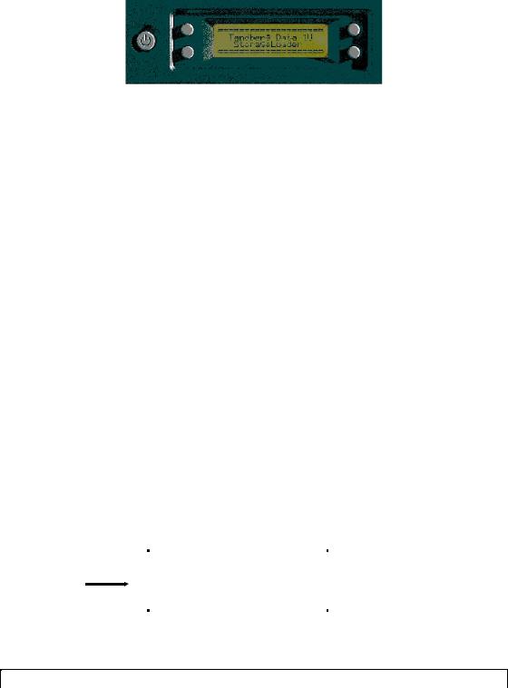
The Local User I nterface ( LUI ) consists of a sm all LCD panel capable of displaying four lines of 20 characters each, and four control buttons, one near each corner of the display. The buttons have soft labels in the corners of the display. The figure below shows the poweron screen on the panel.
Figure 4.1 Power-on Screen
4.1 System Power-On
With m echanical installation and electrical connection com plete, turn on the main power switch. At poweron, for the first few seconds, the unit perform s a sequence of diagnostic tests called PowerOn Self Tests (POST). POST also includes a loop back test of the robot cabling. As the tests are com pleted, the control panel displays a signon message, see figure 4.1.
After successful com pletion of the POST sequence, the loader will respond to SCSI selections. Then the system starts a series of initialization functions, a process that consists of robot calibration operation and cartridge inventory of m agazines and drive. I f a barcode reader is installed and enabled, the barcode labels on the cartridges will be read when running inventory.
During these operations the loader will continuously show the m ap status on the screen, see figure 4.2. The status of all m agazine slots and the drive are initially unknown, and a ‘?’ is displayed for each slot . As the robot searches the m agazine slots for cartridges during Inventory, the display is updated.
Cartridge |
Taking Inventory |
|
Inventory |
Map: ?????_ 7 _ |
Status |
|
|
|
|
|
Figure 4.2 Snapshot while running Inventory
Once the unit |
has com pleted the initialization processes, the |
26 |
StorageLoader Installation and User Manual |

Tandberg Data |
Operation and Configuration |
|
|
|
|
Default screen, see figure 4.3 appears and the loader is ready for SCSI commands.
The Map of the cartridges has the following symbols:
1. A “?” when status is unknown and Inventory is still running.
2. A num ber indicates a slot occupied by a cartridge ( figure 2.3 shows how the cartridge slots are num bered in the magazines)
3. Underscore line indicates an empty slot
4. ‘C’ indicates that a Cleaning Cartridge occupies the slot.
The line below the m ap on the |
default screen gives the drive |
||
status. The drive status displayed is drive dependent. |
|||
|
Robot operation status |
Menu button |
|
|
Soft Label |
||
|
|
|
|
|
|
|
|
Line 2 |
Idle |
Menu |
|
|
|
|
|
Map: __ 3 _ 5 _ 7 _ |
|
||
|
|
||
|
|
|
|
|
Drive Empty |
|
|
|
|
|
|
Figure 4.3 The Default screen
The robot operation status has the following options:
1 |
Idle |
The loader is idle |
|
|
|
2 |
Fetching |
The loader is moving a cartridge from a |
|
|
magazine slot or from the drive to the robot. |
|
|
|
3 |
Stowing |
The loader is moving a cartridge from the robot |
|
|
to a magazine slot or to the drive. |
|
|
|
4 |
Moving |
The loader is moving the robot. |
|
|
|
Table 4-1 Robot Operation Statuses
StorageLoader Installation and User Manual |
27 |
 Loading...