


ST.RE.TT1222.2
Issue 2
ENGLISH (UK)
REFERENCE GUIDE
TT1222 4:2:0
Professional Receiver
Software Version 2.0.0 (and later)
TT1222 4:2:0 Professional Receiver

Preliminary Pages
ENGLISH (UK)
READ THIS FIRST!
If you do not understand the contents of this manual DO NOT OPERATE THIS EQUIPMENT.
Also, translation into any EC official language of this manual can be made available, at your cost.
SVENSKA
LÄS DETTA FÖRST!
ITALIANO
LEGGERE QUESTO AVVISO PER PRIMO!
Se non si capisce il contenuto del presente manuale
NON UTILIZZARE L’APPARECCHIATURA.
È anche disponibile la versione italiana di questo manuale, ma il costo è a carico dell’utente.
NEDERLANDS
LEES DIT EERST!
Om Ni inte förstår informationen i denna handbok
ARBETA DÅ INTE MED DENNA UTRUSTNING.
En översättning till detta språk av denna handbok kan också anskaffas, på Er bekostnad.
PORTUGUÊS
LEIA O TEXTO ABAIXO ANTES DE MAIS NADA!
Se não compreende o texto deste manual NÃO UTILIZE O EQUIPAMENTO.
O utilizador poderá também obter uma tradução do manual para o português à própria custa.
FRANÇAIS
AVANT TOUT, LISEZ CE QUI SUIT!
Si vous ne comprenez pas les instructions contenues dans ce manuel NE FAITES PAS FONCTIONNER CET APPAREIL.
En outre, nous pouvons vous proposer, à vos frais, une version française de ce manuel.
DEUTSCH
LESEN SIE ZUERST DIESEN HINWEIS!
Sollte Ihnen der Inhalf dieses Handbuches nicht klar verständlich sein, dann
BEDIENEN SIE DIESE GERÄTE NICHT!
Eine Übersetzung des Handbuches in diese Sprache ist gegen Berechnung lieferbar.
ESPAÑOL
LEA ESTE AVISO PRIMERO!
Si no entiende el contenido de este manual
NO OPERE ESTE EQUIPO.
Podemos asimismo suministrarle una traducción de este manual al (idioma) previo pago de una cantidad adicional que deberá abonar usted mismo.
Als u de inhoud van deze handleiding niet begrijpt STEL DEZE APPARATUUR DAN NIET IN WERKING.
U kunt tevens, op eigen kosten, een vertaling van deze handleiding krijgen.
SUOMI
LUE ENNEN KÄYTTÖÄ!
Jos et ymmärrä käsikirjan sisältöä ÄLÄ KÄYTÄ LAITETTA.
Käsikirja voidaan myös suomentaa asiakkaan kustannuksella.
DANSK
LÆS DETTE FØRST!
Udstyret må ikke betjenes
MEDMINDRE DE TIL FULDE FORSTÅR INDHOLDET AF DENNE
HÅNDBOG.
Vi kan også for Deres regning levere en dansk oversættelse af denne håndbog.
ΕΛΛΗΝΙΚΑ
∆ΙΑΒΑΣΤΕ ΠΡΩΤΑ ΑΥΤΟ!
Αν δεν καταλάβετε το περιεχόµενο αυτού του βοηθήµατος/εγχειριδίου ΜΗΝ ΛΕΙΤΟΥΡΓΗΣΕΤΕ ΑΥΤΟΝ ΤΟΝ ΕΞΟΠΛΙΣΜΟ.
Επίσης, αυτό το εγχειρίδιο είναι διαθέσιµο σε µετάφραση σε αυτή τη γλώσσα και µπορείτε να το αγοράσετε.
This document and the information contained in it is the property of TANDBERG Television Ltd and may be the subject of patents pending and granted. It must not be used for commercial purposes nor copied, disclosed, reproduced, stored in a retrieval system or transmitted in any form or by any means (electronic, mechanical, photocopying, recording or otherwise), whether in whole or in part, without TANDBERG Television’s prior written agreement.
Issue 2 first published in 2005 by:
TANDBERG TELEVISION LTD
REGISTERED ADDRESS:
UNIT 2 STRATEGIC PARK, COMINES WAY,
HEDGE END, SOUTHAMPTON,
HAMPSHIRE,
SO30 4DA
UNITED KINGDOM
2005 TANDBERG Television Ltd. All rights reserved. |
Registered Company Number 03695535 |
|
|
|
|
Page ii |
Reference Guide: TT1222 4:2:0 Professional Receiver |
|
ST.RE.TT1222.2 |

Preliminary Pages
List of Contents
Chapter 1: Introduction
This chapter describes the purpose of the TT1222 in a typical system, provides a summary of its main features and identifies the controls.
Chapter 2: Installing the Equipment
This chapter provides a guide to installing the equipment, including the suitability of an installation, detailed procedures for the preparation, installation and configuration. This chapter also includes important safety information. It also lists the pin-outs for the various connectors, and details the power cycle procedure.
Chapter 3: Options and Upgrades
This chapter describes the options and upgrades available for the TT1222 4:2:0 Professional Receiver.
Chapter 4 Operating the Equipment Locally
This chapter provides a guide to using the LCD interface and keypad. It also details the setting up, configuration and operating procedures.
Chapter 5: Operating the Equipment Remotely
This chapter provides a guide to configuring the RS-232 remote control port, and preparing the unit for remote operation. This chapter does not detail the remote control procedure itself, as this is detailed in the instructions for the individual control system.
Chapter 6: Alarms/GPOs
This chapter provides a guide to configuring the alarm interface and menus.
Chapter 7: Preventive Maintenance and Fault-Finding
This chapter details routine maintenance tasks to be performed, provides general service advice, and information regarding warranty.
Annex A: Glossary
Annex B: Technical Specification
Annex C: Front Panel LCD Menus
Annex D: Alarm Categories and Conditions
Reference Guide: TT1222 4:2:0 Professional Receiver |
Page iii |
ST.RE.TT1222.2 |
|

Preliminary Pages
About This Reference Guide
This Reference Guide provides instructions and information for the installation and operation of the TT1222 4:2:0 Professional Receiver.
It should be kept in a safe place for reference for the life of the equipment. It is not intended that this Reference Guide is amended by the issue of individual pages. Any revision will be by a complete reissue. Further copies of this Reference Guide can be ordered from the address shown on
page vii. If passing the equipment to a third party, also pass on the relevant documentation.
Issues of this Reference Guide are listed below:
Issue |
Date |
Software Version |
Comments |
|
|
|
|
1 |
Feb 2005 |
1.0.0 |
Initial release. |
|
|
|
|
2 |
Apr 2005 |
2.0.0 |
Minor corrections. Changes to Menus. Addition of Russian |
|
|
|
SECAM Out option module. |
The following documents are also associated with this equipment:
• ST.US.TT1222: TT1222 Professional Receiver User Guide
Acknowledgements
General
All best endeavours have been made to acknowledge registered trademarks and trademarks used throughout this Reference Guide. Any notified omissions will be rectified in the next issue of this Reference Guide. Some trademarks may be registered in some countries but not in others.
Registered trademarks and trademarks used are acknowledged below and marked with their respective symbols. However, they are not marked within the text of this Reference Guide.
Registered Trademarks
AC-3®, Dolby Digital® and Pro Logic® are registered trademarks of Dolby Laboratories Licensing Corporation.
Musicam® is a registered trademark of Thomson and Télédiffusion de France (TDF), Europe and is a registered trademark of CCS (now Musicam USA Incorporated), USA.
Ethernet® is a registered trademark of Xerox Corporation. VideoGuard® is a registered trademark of NDS Limited.
Macrovision
This product incorporates copyright protection technology that is protected by U.S. patents and other intellectual property rights. Use of this copyright protection technology must be authorized by Macrovision Corporation, and is intended for home and other limited viewing uses only unless authorized by Macrovision. Reverse engineering or disassembly is prohibited.
Page iv |
Reference Guide: TT1222 4:2:0 Professional Receiver |
|
ST.RE.TT1222.2 |

Preliminary Pages
Warnings, Cautions and Notes
Heed Warnings
All warnings on the product and in the operating instructions should be adhered to. The manufacturer cannot be held responsible for injuries or damage where warnings and cautions have been ignored or taken lightly.
Read Instructions
All the safety and operating instructions should be read before this product is operated.
Follow Instructions
All operating and use instructions should be followed.
Retain Instructions
The safety and operating instructions should be retained for future reference.
WARNINGS…
WARNINGS GIVE INFORMATION WHICH, IF STRICTLY OBSERVED, WILL PREVENT PERSONAL INJURY OR DEATH, OR DAMAGE TO PERSONAL PROPERTY OR THE ENVIRONMENT. THEY ARE BOXED AND SHADED FOR EMPHASIS, AS IN THIS EXAMPLE, AND ARE PLACED IMMEDIATELY PRECEDING THE POINT AT WHICH THE READER REQUIRES THEM.
CAUTIONS...
Cautions give information which, if strictly followed, will prevent damage to equipment or other goods. They are boxed for emphasis, as in this example, and are placed immediately preceding the point at which the reader requires them.
NOTES...
Notes provide supplementary information. They are highlighted for emphasis, as in this example, and are placed immediately after the relevant text.
EMC Compliance
This equipment is certified to the EMC requirements detailed in Annex B, Technical Specification. To maintain this certification, only use the leads supplied or if in doubt contact Customer Services.
Reference Guide: TT1222 4:2:0 Professional Receiver |
Page v |
ST.RE.TT1222.2 |
|

Preliminary Pages
TANDBERG Television Customer Services
Support Services
Our primary objective is to provide first class customer care that is tailored to your specific business and operational requirements. All levels are supported by one or more service performance reviews to ensure the perfect partnership between TANDBERG Television and your business.
Warranty
All TANDBERG Products and Systems are designed and built to the highest standards and are covered under a comprehensive 12 month warranty.
Levels of Continuing TANDBERG Television Service Support
For stand-alone equipment, then TANDBERG Television BASIC Advantage is the value for money choice for you. BASIC provides you with year-by-year Service long after the warranty has expired.
For systems support you can choose either Gold or Silver Advantage. These packages are designed to save you costs and protect your income through enlisting the help of TANDBERG Television support specialists.
Call TANDBERG Sales for more details.
Where to Find Us
Europe, Middle East |
+44 (0) 23 8048 4455 |
and Africa: |
Fax: +44 (0) 23 8048 4467 |
|
support@tandbergtv.com |
Americas: |
+1 (321) 308 0470 |
|
fieldservice-americas@tandbergtv.com |
China: |
+86 10 6856 0260 (Beijing) |
|
+852 2530 3215 (Hong Kong) |
|
fieldservice-asia@tandbergtv.com |
Australia/NZ: |
+612 8923 0450 |
|
fieldservice-australia@tandbergtv.com |
Internet Address: |
http://www.tandbergtv.com |
Page vi |
Reference Guide: TT1222 4:2:0 Professional Receiver |
|
ST.RE.TT1222.2 |

Preliminary Pages
Technical Training
Training Courses
TANDBERG Television provides a wide range of training courses on the operation and maintenance of our products and on their supporting technologies. TANDBERG can provide both regularly scheduled courses and training tailored to individual needs. Courses can be run either at your premises or at one of our dedicated training facilities.
Where to Find Us
For further information on TANDBERG Television's training programme please contact us:
International Telephone: |
+44 23 8048 4229 |
International Facsimile |
+44 23 8048 4467 |
E-mail Address: |
training@tandbergtv.com |
Internet Address |
http://www.tandbergtv.com |
Customer Services and Technical Training Postal Address
Tandberg Television
Unit 2
Strategic Park
Comines Way
Hedge End
Southampton
Hampshire
SO30 4DA
United Kingdom
Return of Equipment
If you need to return equipment for repair, please contact the Customer Services Helpdesk on +44 (0) 23 8048 4455. A Returns Authorisation Number (RAN) will be issued and full details of the unit will be logged. Please ensure the RAN number is clearly marked on the packaging of the unit. The unit should then be sent to the following address:
Tandberg Television – Customer Services Unit 1
Strategic Park
Comines Way Hedge End Southampton Hampshire SO30 4DA United Kingdom
Technical Publications
If you need to contact TANDBERG Television Technical Publications regarding this publication, e-mail: techpubs@tandbergtv.com.
Reference Guide: TT1222 4:2:0 Professional Receiver |
Page vii |
ST.RE.TT1222.2 |
|

Preliminary Pages
BLANK
Page viii |
Reference Guide: TT1222 4:2:0 Professional Receiver |
|
ST.RE.TT1222.2 |

Contents
1.1 Scope of This Reference Guide................................ |
1-3 |
1.1.1 Who Should Use This Reference Guide....... |
1-3 |
1.1.2What Equipment is Covered by This
|
|
Reference Guide .......................................... |
1-3 |
|
1.1.3 |
Software Version .......................................... |
1-3 |
1.2 |
Summary of Features................................................ |
1-4 |
|
|
1.2.1 |
Main Features............................................... |
1-4 |
|
1.2.2 |
Outputs ......................................................... |
1-5 |
|
|
Video Outputs............................................... |
1-5 |
|
|
Audio Outputs............................................... |
1-5 |
|
|
Data Output .................................................. |
1-5 |
|
|
Relay / GPO Output...................................... |
1-5 |
|
|
ASI Output (Option) ...................................... |
1-5 |
|
1.2.3 |
Conditional Access ....................................... |
1-6 |
1.3 |
TT1222 Control Modes ............................................. |
1-6 |
|
|
1.3.1 |
Introduction................................................... |
1-6 |
|
1.3.2 |
Remote Control ............................................ |
1-6 |
|
1.3.3 |
Local Control ................................................ |
1-6 |
1.4 |
Guided Tour .............................................................. |
1-7 |
|
|
1.4.1 |
Construction ................................................. |
1-7 |
|
1.4.2 |
Front Panel Controls..................................... |
1-7 |
|
|
Overview....................................................... |
1-7 |
|
|
Edit and Save ............................................... |
1-8 |
|
|
Cancel an Edit .............................................. |
1-8 |
|
1.4.3 |
Front Panel LED ........................................... |
1-8 |
1.4.4Conditional Access – DVB Common
Interface........................................................ |
1-8 |
1.4.5 Rear Panel.................................................... |
1-8 |
Chapter 1
Introduction
List of Figures
Figure 1.1: Front View ................................................................... |
1-3 |
Figure 1.2: Navigating the Menus.................................................. |
1-7 |
Figure 1.3: Editing Values in a Menu............................................. |
1-7 |
List of Tables
Table 1.1: Equipment Model Descriptions..................................... |
1-3 |
Reference Guide: TT1222 4:2:0 Professional Receiver |
Page 1-1 |
ST.RE.TT1222.2 |
|

Introduction
BLANK
Page 1-2 |
Reference Guide: TT1222 4:2:0 Professional Receiver |
|
ST.RE.TT1222.2 |
Introduction
1.1Scope of This Reference Guide
1.1.1Who Should Use This Reference Guide
This Reference Guide is written for operators/users of the TANDBERG TT1222 Professional Receiver. It describes the unit’s functions and operation. The Reference Guide is written to assist in the installation and day-to-day care and operation of the unit. It does not include any maintenance information or procedures which would require the removal of covers.
WARNING…
DO NOT REMOVE THE COVERS OF THIS EQUIPMENT. HAZARDOUS VOLTAGES ARE PRESENT WITHIN THIS EQUIPMENT AND MAY BE EXPOSED IF THE COVERS ARE REMOVED. ONLY TANDBERG TELEVISION TRAINED AND APPROVED SERVICE ENGINEERS ARE PERMITTED TO SERVICE THIS EQUIPMENT.
CAUTION…
Unauthorised maintenance or the use of non-approved replacements may affect the equipment specification and invalidate any warranties.
1.1.2What Equipment is Covered by This Reference Guide
The base model of the TT1222 Receiver comprises of an enclosure and Base Board only.
Figure 1.1: Front View
There are a number of option modules which can be added to the base unit to provide additional inputs and outputs. Information regarding the option modules can be found in Chapter 3, Options.
Table 1.1: Equipment Model Descriptions
Model Number |
Marketing Code |
Description |
TT1222 Receiver |
TT1222/CIBAS |
Professional Receiver. 1U MPEG-2 4:2:0 Receiver. |
|
|
Common Interface CA unit with: 2 x Composite Video Outputs, 2 x Audio |
|
|
Outputs, RS-232 Data, RS-232 Remote Control, 5 x General Purpose |
|
|
Outputs (GPO), 1 x Alarm Relay and 1 x Ethernet Port (for future use) |
1.1.3Software Version
This Reference Guide has been written to cover the functionality of software version 2.0.0 (and later). The current software version can be found in the Properties Menu.
Reference Guide: TT1222 4:2:0 Professional Receiver |
Page 1-3 |
ST.RE.TT1222.2 |
|

Introduction
1.2Summary of Features
1.2.1Main Features
The Receiver is fully compliant with the appropriate sections of the MPEG-21 and DVB-S2 specifications.
The TT1222 offers the following features:
•
•
Signal Inputs: |
|
|
QPSK L-Band (Option)3 |
- |
1 x QPSK via F-connector |
ASI input (Option)3 |
- |
1 x ASI via BNC connector |
Signal Outputs: |
|
|
Composite Video Outputs - |
2 x CVBS via BNC connectors |
|
Audio outputs - 2 x Audio via 9-way D-Type connectors (Analogue and Digital)
•
•
•
ASI output (Option)3 |
- |
1 x ASI via BNC connector |
Video Decoding:
4:2:0 MP@ML mode support video resolutions up to 720 pixels x 576 active lines (25 frame/s) or 720 pixels x 480 active lines (30 frame/s)
No 4:2:2 support
Support for PAL- (B, D, G, H, I, M and Combination N) Support for SECAM (B, G, H, K1, L) Line ID
Support for SECAM (D, K) Field ID (Option)3 Support for NTSC (M)
Audio Decoding:
Decoding of two separate audio services. (Audio 1 is dependent on the TV service selection. Audio 2 audio is individually configured).
Support of MPEG-1 Layer I and II (Musicam) Support of Dolby Digital AC-3 downmix Sampling rates 32, 44.1 and 48 kHz
All MPEG-1 Layer I and II bit-rates
Vertical Blanking Interval (VBI) Signalling Support:
In 625 lines: VITS test lines, WSS, WSS-AFD, VPS, WST (EBU) Teletext insertion and Inverted Teletext is supported in the analogue video output.
In 525 lines: VITS test lines, Closed Captions and V.Chip signalling are supported in the analogue video output.
•Service Selection:
Chosen from a menu list of available services carried in the currently received transport stream in PSI/SI enabled mode.
•Conditional Access:
DVB Common Interface
1Moving Pictures Expert Group: MPEG-2 specification ISO 13818.
2European Digital Video Broadcasting (DVB) Project. EN 300 421 Digital broadcasting systems for television, sound and data services: Framing structure, channel coding, and modulation for the 11/12 GHz satellite service.
3See Chapter 3 for details of options.
Page 1-4 |
Reference Guide: TT1222 4:2:0 Professional Receiver |
|
ST.RE.TT1222.2 |

Introduction
BISS Modes 1 and E
•Front Panel Controls and Indications:
•
•
•
A 2 row by 20 character back lit LCD display provides information and allows operator choice entry
Four pushbuttons provide the control interface in conjunction with the LCD display
Single LED provides status information
Data:
Low speed data: RS-232 asynchronous (up to 115.2 kbit/s)
Remote Control:
RS-232, TANDBERG proprietary control solution
Control
1 Relay available
5 General Purpose Outputs
1.2.2Outputs
Video Outputs
Two BNC composite video outputs are present on the rear of the unit.
Audio Outputs
There are two audio outputs available on 9-way D-sub connectors at the rear panel. Each connector provides one balanced analogue audio pair and one unbalanced digital signal. Dependent on the input, the user can configure the analogue output to present the audio as one stereo, a dualmono or two independent mono channels.
Data Output
RS-232 asynchronous low speed data output carried on a 9-way D-sub connector, available on all models. The data output rate is configurable from 75 bit/s to 115200 bit/s.
Relay / GPO Output
The unit can be set up to produce warnings and alarms when particular conditions occur.
The relay output can be set up to trigger on one or more ‘error’ states. When the equipment has detected an error, the relay is triggered and the front panel alarm LED is also activated. For instructions on configuring the alarms, see Chapter 6, Alarms/GPOs. For a description of the alarm relay, see Chapter 2, Installing the Equipment.
The same connector supports five GPOs (General Purpose Outputs). These can be set up to trigger on a single or numerous events. These signals are independent of the relay signal.
ASI Output (Option)
A single ASI output is available if the hardware option TT1222/HWO/ASI/OUT is purchased.
More detail on the option modules can be found in Chapter 3, Options.
Reference Guide: TT1222 4:2:0 Professional Receiver |
Page 1-5 |
ST.RE.TT1222.2 |
|

Introduction
1.2.3Conditional Access
The transport stream received by the IRD may be encrypted. The CA system is used to decrypt the required components of the transport stream so that they can be decoded.
The following conditional access system is available on the TT1222 Receiver.
•
•
DVB Common Interface
BISS Modes 1 and E
1.3TT1222 Control Modes
1.3.1Introduction
The TT1222 is designed for unattended operation. Once set up, it requires no further attention except to ensure that the fan is working. There are two control modes associated with the Receiver, local (keypad), and remote (RS-232) control.
1.3.2Remote Control
This state is entered when the Ctrl Mode setting in the Setup:Control menu is set to remote. When the Decoder is remotely controlled, local control is disabled until the Decoder is configured for the local mode.
1.3.3Local Control
Local control allows parameters to be entered and chosen using the four arrow keys.
The arrow keys roles and functions change, depending on what kind of menu or screen is available at the moment.
The Up/Down arrow keys are used for previous/next item in a menu, previous/next option in an option select menu (for instance, on or off) or the higher/lower digit in a numerical entry menu.
The Right/Left arrow keys are used to enter/leave a menu or submenu, and to select the next or previous digit in a numerical entry menu.
Page 1-6 |
Reference Guide: TT1222 4:2:0 Professional Receiver |
|
ST.RE.TT1222.2 |
Introduction
1.4Guided Tour
1.4.1Construction
The Receiver is constructed using a screened fan-ventilated chassis. All operational inputs and outputs are via the rear panel connectors. The unit may be operated freestanding on a horizontal flat surface, or mounted in a 19-inch rack. 1RU rack height is required. It is important that horizontal airflow is not obstructed, to maintain the airflow required to cool the unit.
1.4.2Front Panel Controls
Overview
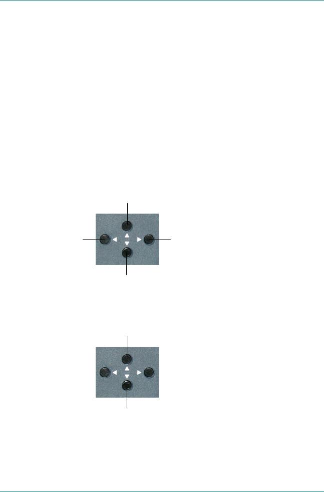
The front panel is fitted with a keypad that is used to set up and monitor the unit. Information on the use of these controls is given in Chapter 4, Operating the Equipment Locally. It gives an overview on how to navigate the menus. Figure 1.3 explains how to edit these values once a menu item is selected.
Move cursor up / scroll up
Return to previous |
Select item at cursor |
menu |
Move cursor down / scroll down
Figure 1.2: Navigating the Menus
Increment value
Position Cursor |
|
|
|
Position Cursor |
|
|
|
Decrement value
Figure 1.3: Editing Values in a Menu.
Reference Guide: TT1222 4:2:0 Professional Receiver |
Page 1-7 |
ST.RE.TT1222.2 |
|

Introduction
Edit and Save
In the edit mode, when the correct value is in place, exit and save by pressing multiple times to the right, to move the cursor outside the edit area. When the cursor leaves the edit area, the new setting will be saved, and the keypad will revert to the navigation mode.
Cancel an Edit
In the edit mode, if you have incorrectly entered a value, cancel and exit by pressing multiple times to the left, to move the cursor outside the edit area. When the cursor leaves the edit area, the previous setting will reappear, and the keypad will revert to the navigation mode.
NOTE…
Keypad access may be locked, easily recognised by the small lock in the top left corner of the display. To navigate the menus, escape the locked mode by pressing left, right, 3 x left and then 3 x right in sequence. This will take you from the default status screen, to the main menu.
1.4.3Front Panel LED
The unit is fitted with one LED, showing the status of the unit. When the LED lights up red, an alarm condition has been met, according to the alarm set-up described in Annex D, Alarm Categories and Conditions.
1.4.4Conditional Access – DVB Common Interface
There is one slot on the rear of the unit, to allow the insertion of a DVB Common Interface Module.
1.4.5Rear Panel
All input and output connectors are located on the rear panel. Connector descriptions are given in Chapter 2, Installing the Equipment.
Page 1-8 |
Reference Guide: TT1222 4:2:0 Professional Receiver |
|
ST.RE.TT1222.2 |

Chapter 2
Installing the Equipment
Contents
2.1 |
Read this First!.......................................................... |
2-3 |
|
|
2.1.1 |
Handling ....................................................... |
2-3 |
|
2.1.2 |
Installing the Equipment ............................... |
2-3 |
|
2.1.3 |
Lifting ............................................................ |
2-3 |
|
2.1.4 |
Site Requirements ........................................ |
2-3 |
|
|
Power Supplies............................................. |
2-3 |
|
|
Environment ................................................. |
2-3 |
|
|
Lightning Protection...................................... |
2-3 |
2.2 |
Preliminary Checks ................................................... |
2-4 |
|
|
2.2.1 |
Mechanical Inspection .................................. |
2-4 |
|
2.2.2 Moving the Equipment Safely....................... |
2-4 |
|
2.3 |
Installing the Equipment............................................ |
2-4 |
|
|
2.3.1 |
Fixing ............................................................ |
2-4 |
|
2.3.2 |
Ventilation..................................................... |
2-4 |
|
|
Openings in the Covers ................................ |
2-4 |
|
|
Care in Positioning ....................................... |
2-5 |
|
|
Protection From Moisture ............................. |
2-5 |
|
2.3.3 Installing Cables – Safety ............................. |
2-5 |
|
2.4 |
EMC Compliance Statements................................... |
2-6 |
|
|
2.4.1 EN 55022 and AS/NZS 3548........................ |
2-6 |
|
|
2.4.2 |
FCC .............................................................. |
2-6 |
2.4.3Connecting to a Public
|
Telecommunication System ......................... |
2-6 |
2.5 AC Supply Voltage and Fusing – Safety |
|
|
Information ................................................................ |
2-6 |
|
2.5.1 |
AC Power Supply ......................................... |
2-6 |
2.5.2 |
Technical Earth............................................. |
2-7 |
2.5.3 AC Power Supply Cord................................. |
2-7 |
|
|
General......................................................... |
2-7 |
|
Disposal of Moulded Plugs ........................... |
2-8 |
|
Wire Colours................................................. |
2-8 |
2.5.4Connecting the Equipment to the AC
|
Power Supply................................................ |
2-8 |
2.6 Signal Connections.................................................... |
2-9 |
|
2.6.1 |
Overview ....................................................... |
2-9 |
2.6.2 |
Input Connectors........................................... |
2-9 |
|
QPSK Input (TT1222/HWO/QPSK)............... |
2-9 |
|
ASI Input (TT1222/HWO/ASI/IN) ................ |
2-10 |
|
RS232 Remote............................................ |
2-10 |
2.6.3 |
Output Connectors...................................... |
2-10 |
|
Analogue Video Outputs ............................. |
2-10 |
|
Analogue/Digital Audio Outputs .................. |
2-11 |
|
Audio Lead.................................................. |
2-12 |
|
ASI Output (TT1222/HWO/ASI/OUT).......... |
2-12 |
|
RS-232 Low-speed Asynchronous Data |
|
|
Output ......................................................... |
2-12 |
|
Alarm Relay/General Purpose Output......... |
2-13 |
2.6.4 |
RS232 Remote............................................ |
2-14 |
2.6.5 |
Conditional Access Interface ...................... |
2-14 |
List of Figures
Figure 2.1: Openings in the Cabinet.............................................. |
2-4 |
Figure 2.2: Technical Earth Connector.......................................... |
2-7 |
Figure 2.3: Signal Connections ..................................................... |
2-9 |
Figure 2.4: Example Rear Panel View (Model fitted with |
|
QPSK Option)............................................................... |
2-9 |
Figure 2.5: Audio Cable............................................................... |
2-12 |
List of Tables
Table 2.1: Supply Cord Wiring Colours ......................................... |
2-8 |
Table 2.2: Non Standard Supply Cord Wire Colours..................... |
2-8 |
Table 2.3: RS-232 Connector...................................................... |
2-10 |
Table 2.4: Analogue Video Connector......................................... |
2-11 |
Table 2.5: Audio Connectors 1 and 2.......................................... |
2-11 |
Table 2.6: RS-232 Low-speed Data Connector .......................... |
2-13 |
Table 2.7: Relay/GPO Pin Allocation........................................... |
2-13 |
Reference Guide: TT1222 4:2:0 Professional Receiver |
Page 2-1 |
ST.RE.TT1222.2 |
|

Installing the Equipment
Table 2.8: |
RS-232 Connector...................................................... |
2-14 |
Table 2.9: |
Conditional Access..................................................... |
2-14 |
Page 2-2 |
Reference Guide: TT1222 4:2:0 Professional Receiver |
|
ST.RE.TT1222.2 |

Installing the Equipment
2.1Read this First!
2.1.1Handling
The TT1222 must be handled and installed carefully and thoughtfully to prevent safety hazards and damage.
2.1.2Installing the Equipment
Follow the instructions for installation and only use installation accessories recommended by the manufacturers.
Ensure that personnel designated to install the unit have the appropriate skill and knowledge. If in any doubt, please contact Customer Services (see Preliminary pages for contact details).
When rack mounted, this unit must have shelf supports as well as being fixed at the front panel. Do not use this product as a support for any other equipment.
2.1.3Lifting
Although this is a light product, in some circumstances it might be awkward to lift, especially when packed. In which case, do not attempt to lift or move it without proper assistance or equipment. If in doubt, get help.
2.1.4Site Requirements
Power Supplies
See Annex B, Technical Specification for a full specification.
Environment
See Annex B, Technical Specification for a full specification.
Do not install this product in areas of high humidity or where there is danger of water ingress.
Lightning Protection
WARNING…
IF THE UNIT HAS BEEN SUBJECT TO A LIGHTNING STRIKE OR POWER SURGE WHICH HAS STOPPED IT WORKING, DISCONNECT THE POWER IMMEDIATELY. DO NOT REAPPLY POWER UNTIL IT HAS BEEN CHECKED FOR SAFETY. IF IN DOUBT, CONTACT TANDBERG TELEVISION CUSTOMER SERVICES.
Where appropriate, ensure this product has an adequate level of lightning protection. Alternatively, during a lightning storm or when it is left unattended and unused for long periods of time, unplug it from the supply outlet and disconnect the output equipment. This prevents damage to the product due to lightning and power line surges.
Reference Guide: TT1222 4:2:0 Professional Receiver |
Page 2-3 |
ST.RE.TT1222.2 |
|

Installing the Equipment
2.2Preliminary Checks
2.2.1Mechanical Inspection
Inspect the equipment for damage-in-transit. If in doubt, please contact TANDBERG Television Customer Services (see Preliminary pages).
WARNING…
REMOVING THE COVERS OF THIS EQUIPMENT MAY INVALIDATE ANY WARRANTIES, CAUSE A SAFETY HAZARD AND / OR AFFECT THE EMC PERFORMANCE. CHECK WITH TANDBERG TELEVISION CUSTOMER SERVICES.
2.2.2Moving the Equipment Safely
Do not place this product on an unstable cart, stand, bracket, or table. The product may fall, causing serious injury and serious damage to the product. Use only with a cart, stand, bracket or table recommended by TANDBERG Television.
An appliance and cart combination should be moved with care. Quick stops, excessive force, and uneven surfaces may cause the appliance and cart combination to overturn. Do not move or carry the equipment whilst it is still connected to the supply or other leads, is live, or is in operation.
2.3Installing the Equipment
2.3.1Fixing
The TT1222 is designed for fixed use only and has been shipped with fixing brackets suitable for a standard 19-inch rack. When installed in a rack, it should be secured by using the fixing brackets. In addition, support shelves must be used to reduce the weight on the brackets. Ensure it is firmly and safely located and it has an adequate free-flow of air.
A freestanding unit should be installed on a secure horizontal surface where it is unlikely to be knocked or its connectors and leads disturbed.
2.3.2Ventilation
Openings in the Covers
Openings in the cabinet are provided for ventilation. These ensure reliable operation of the unit and protect it from overheating. These openings must not be blocked or covered.
Figure 2.1: Openings in the Cabinet
Page 2-4 |
Reference Guide: TT1222 4:2:0 Professional Receiver |
|
ST.RE.TT1222.2 |
Installing the Equipment
Care in Positioning
CAUTIONS…
1.The fan and openings contained within this unit are not fitted with a dust / insect filter. Pay attention to the environment in which it is to be used.
2.Do not install units so that the air intake for one unit aligns with the outlet of another. Provide baffles and adequate spacing.
The TT1222 should never be placed near or over a radiator or other source of heat. It should not be placed in a built-in installation such as a rack unless proper ventilation is provided and the instructions have been adhered to.
Allow at least 40 mm free air space at each side of the equipment to ensure adequate cooling. Unit in racks can be stacked with no space in between. Racks containing stacked equipment may need to be forced-air cooled to reduce the ambient temperature within the rack.
Protection From Moisture
Do not install this unit in areas of high humidity or where there is a danger of water or moisture entering the equipment.
2.3.3Installing Cables – Safety
Power supply cables should be routed so that they are not likely to be walked on or pinched by items placed upon or against them. Pay particular attention to cables at plugs, convenience receptacles, and the point where they exit from the appliance.
Do not run ac power cables in the same duct as signal leads. Do not move or install equipment whilst it is still attached to the mains supply. Ensure that safety and ESD precautions are observed whilst interconnecting equipment.
WARNING…
WHEN CONNECTING THE F-CONNECTOR CABLE FROM THE ANTENNA TO THE QPSK
F-CONNECTOR INPUT, IT IS IMPORTANT TO MAKE SURE THAT:
1.THE UNIT IS PROPERLY GROUNDED.
2.THE CABLE SCREEN IS THE FIRST POINT OF CONTACT BETWEEN THE F-CONNECTOR AND THE CABLE.
THIS IS TO MAKE SURE THAT THE CABLE AND UNIT ARE AT THE SAME ELECTRICAL POTENTIAL WHEN THE CONNECTION IS MADE, AND TO AVOID DAMAGE TO THE EQUIPMENT.
Reference Guide: TT1222 4:2:0 Professional Receiver |
Page 2-5 |
ST.RE.TT1222.2 |
|

Installing the Equipment
2.4EMC Compliance Statements1
2.4.1EN 55022 and AS/NZS 3548
This is a Class A product. In a domestic environment this product may cause radio interference in which case the user may be required to take adequate measures.
2.4.2FCC
This equipment have been tested and found to comply with the limits for a Class A digital device, pursuant to part 15 of the FCC rules. These limits are designed to provide reasonable protection against harmful interference when the equipment is operated in a commercial environment.
This equipment generates, uses, and can radiate radio frequency energy and, if not installed and used in accordance with the Reference Guide, may cause harmful interference to radio communications. Operation of this equipment in a residential area is likely to cause harmful interference in which case the user will be required to correct the interference at his own expense.
2.4.3Connecting to a Public Telecommunication System
CAUTION…
TT1222 is not constructed for electrical connection directly to any public telecommunication system. None of the output signals shall be distributed directly from TT1222 to a public telecommunication system leaving the building without using some kind of interface in between such as a telecom terminal, switch or similar unit. Such kind of buffer is required to achieve a protective electrical barrier between the public telecommunication system and TT1222. This electrical barrier is required to achieve protection against lightning or faults in nearby electrical installations.
2.5AC Supply Voltage and Fusing – Safety Information
2.5.1AC Power Supply
The TT1222 is fitted with a wide-ranging power supply. It is suitable for supply voltages of 100-240 Vac -10% +6% at 50/60 Hz nominal. It is designed for use in ambient temperature in the range of 0°C to +50°C. The full technical specification is given in Annex B, Technical Specification.
WARNING…
THE TT1222 SHOULD ONLY BE OPERATED FROM THE TYPE OF POWER SOURCE INDICATED ON THE MARKING LABEL. IF YOU ARE NOT SURE OF THE TYPE TO YOUR BUSINESS, CONSULT YOUR APPLIANCE DEALER OR LOCAL POWER COMPANY. DO NOT OVERLOAD WALL OUTLETS AND EXTENSION CORDS AS THIS CAN RESULT IN A RISK OF FIRE OR ELECTRIC SHOCK.
1 The EMC information was correct at the time of manufacture. The EMC tests were performed with the technical earth attached.
Page 2-6 |
Reference Guide: TT1222 4:2:0 Professional Receiver |
|
ST.RE.TT1222.2 |
Installing the Equipment
NOTE…
There is no user-replaceable fuse in the rear of the unit.
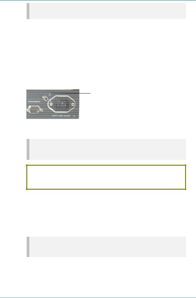
2.5.2Technical Earth
The Technical Earth provides a suitable connection between the TT1222 and the installation to give a low impedance path at normal operating frequencies. A terminal at the rear panel (left of the power socket) is provided to:
1.Ensure all equipment chassis fixed within a rack are at the same technical earth potential. To do this, connect a wire between the Technical earth terminal and a suitable point on the rack.
2.Eliminate the migration of stray charges when connecting between equipment.
Location of the Technical Earth
Figure 2.2: Technical Earth Connector
NOTE…
The technical earth shall be fitted with a bolt of M4 x 6 dimensions, 4 millimetres in diameter, and no longer than 6 millimetres.
CAUTION…
It is strongly recommended that the Technical Earth terminal at the rear panel of the equipment be connected to a site Technical Earth before any external connections are made and the equipment is powered. This limits the migration of stray charges.
2.5.3AC Power Supply Cord
General
A mains cord is normally supplied with this product. It is fitted with a moulded plug suitable either for mainland Europe, the UK, Australia or USA as advised when ordered.
NOTE…
The TT1222 is not fitted with an ac power supply ON/OFF switch. Ensure the socket-outlet supplying the equipment is installed near the equipment, so that it is easily accessible.
When replacing the power cord in the USA, make sure to always replace it with a cord of the same type. The cord should be of type: Feller type SVT cord rated 3x18 AWG with plug 498 G and appliance coupler C13.
Reference Guide: TT1222 4:2:0 Professional Receiver |
Page 2-7 |
ST.RE.TT1222.2 |
|

Installing the Equipment
Disposal of Moulded Plugs
If the moulded plug fitted to the mains cable supplied with this equipment is not required, use another cable. If the supplied plug is to be changed, cut it off and dispose of it safely.
WARNING…
IF THE MOULDED PLUG FITTED TO THE MAINS CABLE SUPPLIED WITH THIS EQUIPMENT IS NOT REQUIRED; PLEASE CUT IT OFF AND DISPOSE OF IT SAFELY. FAILURE TO DO THIS MAY ENDANGER LIVES AS LIVE ENDS MAY BE EXPOSED IF THE REMOVED PLUG IS INSERTED INTO A MAINS OUTLET.
Wire Colours
The wires in the supply cord are coloured as shown in Table 2.1.
Table 2.1: Supply Cord Wiring Colours
|
UK (BS1363) |
Europe (CEE 7/7) |
USA (NEMA 5-15P) |
|
|
|
|
Earth |
Green-and-yellow |
Green-and-yellow |
Green |
|
|
|
|
Neutral |
Blue |
Blue |
White |
|
|
|
|
Live |
Brown |
Brown |
Black |
|
|
|
|
If the colours do not correspond with the coloured markings identifying the terminals in a locally supplied plug, proceed as in Table 2.2 (included for reference).
Table 2.2: Non Standard Supply Cord Wire Colours
Wire Colour (UK) |
Action |
|
|
green-and-yellow |
...must be connected to the terminal in the plug which is marked with the letter E or the safety |
|
earth symbol or coloured green or green-and-yellow. |
blue |
...must be connected to the terminal in the plug which is marked with the letter N or coloured |
|
black. |
brown |
...must be connected to the terminal in the plug which is marked with the letter L or coloured |
|
red. |
2.5.4Connecting the Equipment to the AC Power Supply
As there is no power switch fitted to this unit, ensure the local ac power supply is switched OFF before connecting the supply cord.
Connect the mains lead to the TT1222 and then to the local supply.
Page 2-8 |
Reference Guide: TT1222 4:2:0 Professional Receiver |
|
ST.RE.TT1222.2 |

Installing the Equipment
2.6Signal Connections
2.6.1Overview
Figure 2.3 shows the signal connections for the TT1222 Receiver and options.
RS232 / RS485 Remote Control
NOT USED
QPSK Input
Option
Modules
ASI Input
AC Mains Supply
TT1222 Professional Receiver |
|
Motherboard |
|
(TT1222 / CIBAS) |
|
CONDITIONAL ACCESS INTERFACE |
|
|
RELAY/GPO |
|
RS232DATA |
|
CVBS1 |
|
CVBS2 |
RS232 REMOTE |
AUDIO1 |
ETHERNET |
AUDIO2 |
Russian SECAM Output Card |
|
(TT1222 / HWO / RS) |
|
QPSK Input Card |
|
(TT1222 / HWO / QPSK) |
|
QPSK IN |
|
DC OUT |
|
ASI Input Card |
|
(TT1222 / HWO / ASI / IN) |
|
ASI IN |
|
ASI Output Card |
|
(TT1222 / HWO / ASI / OUT) |
|
|
ASI OUT |
Power |
Supply Unit |
Conditional Access PCMCIA slot
1 x Relay and 5 x General Purpose
Outputs
Low Speed Asynchronous Data Analogue Video Out
Analogue Video Out Analogue / Digital Audio Out Analogue / Digital Audio Out
ASI Output
Figure 2.3: Signal Connections
Figure 2.4: Example Rear Panel View (Model fitted with QPSK Option)
2.6.2Input Connectors
QPSK Input (TT1222/HWO/QPSK)
See Chapter 3, Options for details.
Reference Guide: TT1222 4:2:0 Professional Receiver |
Page 2-9 |
ST.RE.TT1222.2 |
|

Installing the Equipment
ASI Input (TT1222/HWO/ASI/IN)
See Chapter 3, Options for details.
RS232 Remote
The RS-232 connector labelled remote on the back of the equipment allows for connection to a PC for remote control, software upload or debug purposes. The SETUP OUTPUTS RS232 REMOTE menu is used to configure the parameters for communicating with the unit. For more information about remote control, see Chapter 4: Operating the Equipment Remotely.
Table 2.3: RS-232 Connector
Item |
Specification |
|
|
|
|
|
|
Connector type |
9-way D-type, Male |
|
|
|
|
|
|
Connector designation |
RS232 REMOTE |
|
|
|
|
|
|
Pin-outs |
Pin |
Function |
Direction |
|
|
|
|
|
1 |
Reserved |
- |
|
|
|
|
|
2 |
Data receive (Rx) |
Input |
|
|
|
|
|
3 |
Data transmit (Tx) |
Output |
|
|
|
|
|
4 |
Reserved |
- |
|
|
|
|
|
5 |
Ground |
- |
|
|
|
|
|
6 |
Reserved |
- |
|
|
|
|
|
7 |
Reserved |
- |
|
|
|
|
|
8 |
Reserved |
- |
|
|
|
|
|
9 |
Reserved |
- |
|
|
|
|
2.6.3 Output Connectors
Analogue Video Outputs
This is a pair of BNC sockets, which provide a composite video output. The default output standard is configured using the
Setup Video Setup Default O/P menu.
Page 2-10 |
Reference Guide: TT1222 4:2:0 Professional Receiver |
|
ST.RE.TT1222.2 |

Installing the Equipment
Table 2.4: Analogue Video Connector
Item |
|
Specification |
|
|
|
Connector type |
2 x BNC, Female |
|
Output format* |
PAL (B, D, G, H, I, Combination N, M) |
|
|
|
SECAM (B, G, H, K1, L) with Line ID |
|
|
SECAM (D,K) with Field ID setting (if Russian SECAM option module fitted)2 |
|
|
NTSC (M) |
|
|
*Output format varies with menu settings and incoming MPEG data. |
Connector designation |
CVBS 1, CVBS 2 |
|
Pin: |
Centre |
Video output |
|
Shield |
Ground / Chassis |
Impedance |
75 Ω |
|
Analogue/Digital Audio Outputs
The Decoder is fitted with two 9-pin D-type connectors each carrying one analogue audio pair and one digital audio signal.
Table 2.5: Audio Connectors 1 and 2
Item |
Specification |
|
|
|
|
Connector type |
9-way D-type, Male |
|
|
|
|
Connector designation |
AUDIO 1, AUDIO 2 |
|
|
|
|
Output format |
Balanced |
|
|
|
|
Nominal output level |
0 dBm in 600 Ω (0 dBu) adjustable from –9 dB to +3 dB in 0.1 dB steps. |
|
|
|
|
Output impedance |
< 50 Ω |
|
|
|
|
Idle channel noise |
< -74 dB |
|
|
|
|
Pin-outs: |
Pin |
Function |
|
|
|
|
1 |
Unbalanced Digital audio |
|
|
|
|
2 |
Ground |
|
|
|
|
3 |
Left + |
|
|
|
|
4 |
Right + |
|
|
|
|
5 |
Ground |
|
|
|
|
6 |
Reserved |
|
|
|
|
7 |
Ground |
|
|
|
|
8 |
Left - |
|
|
|
|
9 |
Right - |
|
|
|
The TT1222 is able to decode and output Dolby AC3 encoded audio components on both audio outputs.
NOTE…
Dolby AC-3 decoding shall be enabled and disabled by licence key. For more information, please contact TANDBERG Television Customer Services.
2 See Chapter 3 for details of Options
Reference Guide: TT1222 4:2:0 Professional Receiver |
Page 2-11 |
ST.RE.TT1222.2 |
|

Installing the Equipment
Audio Lead
Two audio cables are supplied with TT1222 units, as shown in Figure 2.5. These cables support analogue left and right channels and unbalanced digital audio.
Figure 2.5: Audio Cable
ASI Output (TT1222/HWO/ASI/OUT)
See Chapter 3, Options for details.
RS-232 Low-speed Asynchronous Data Output
A 9-way D-type female connector is provided as the connection for low-speed data output.
Page 2-12 |
Reference Guide: TT1222 4:2:0 Professional Receiver |
|
ST.RE.TT1222.2 |

Installing the Equipment
Table 2.6: RS-232 Low-speed Data Connector
Item |
Specification |
|
|
|
|
Connector type |
9-way D-type, Female |
|
|
|
|
Connector designation |
RS232 DATA |
|
|
|
|
Output rate |
75, 110, 150, 200,300, 600, 1050, 1200, 2400, 4800, 9600, 19200, 38400, |
|
|
57600 or 115200 baud selectable |
|
Pin-outs |
Pin |
Function |
|
|
|
|
1 |
Reserved |
|
|
|
|
2 |
Data Transmit (Tx) - data output |
|
|
|
|
3 |
Data Receive (Rx) - data input |
|
|
|
|
4 |
Reserved |
|
|
|
|
5 |
Ground |
|
|
|
|
6 |
Reserved |
|
|
|
|
7 |
Reserved |
|
|
|
|
8 |
Reserved |
|
|
|
|
9 |
Reserved |
|
|
|
Alarm Relay/General Purpose Output
A 9-way D-type female connector is provided as an alarm/controlled relay mechanism.
The TT1222 has a configurable alarm contact closure. The alarm is activated following the occurrence of an alarm condition. It is possible to control the alarm conditions via a user interface.
In addition, the TT1222 supports five configurable general purpose output pins. These are also controllable via the user interface.
Table 2.7: Relay/GPO Pin Allocation
Parameter |
Specification |
|
|
Relay 1, Open on alarm |
Pin 9 |
|
|
Relay 1, common |
Pin 4 |
|
|
Relay 1, Closed on alarm |
Pin 8 |
|
|
GPO 1 |
Pin 1 |
|
|
GPO 2 |
Pin 2 |
|
|
GPO 3 |
Pin 3 |
|
|
GPO 4 |
Pin 6 |
|
|
GPO 5 |
Pin 7 |
|
|
GPO ground |
Pin 5 |
|
|
Reference Guide: TT1222 4:2:0 Professional Receiver |
Page 2-13 |
ST.RE.TT1222.2 |
|

Installing the Equipment
2.6.4RS232 Remote
The RS-232 connector labelled remote on the back of the equipment allows for connection to a PC for remote control, software upload or debug purposes. The SETUP OUTPUTS RS232 REMOTE menu is used to configure the parameters for communicating with the unit. For more information about remote control, see Chapter 4: Operating the Equipment Remotely.
Table 2.8: RS-232 Connector
Item |
Specification |
|
|
|
|
|
|
Connector type |
9-way D-type, Male |
|
|
|
|
|
|
Connector designation |
RS232 REMOTE |
|
|
|
|
|
|
Pin-outs |
Pin |
Function |
Direction |
|
|
|
|
|
1 |
Reserved |
- |
|
|
|
|
|
2 |
Data receive (Rx) |
Input |
|
|
|
|
|
3 |
Data transmit (Tx) |
Output |
|
|
|
|
|
4 |
Reserved |
- |
|
|
|
|
|
5 |
Ground |
- |
|
|
|
|
|
6 |
Reserved |
- |
|
|
|
|
|
7 |
Reserved |
- |
|
|
|
|
|
8 |
Reserved |
- |
|
|
|
|
|
9 |
Reserved |
- |
|
|
|
|
2.6.5 Conditional Access Interface
Table 2.9 lists the conditional access schemes supported by the TT1222.
Table 2.9: Conditional Access
Parameter |
Specification |
|
|
Common Interface |
According to PCMCIA ‘PC Card Standard, release 3’ |
|
|
Fixed key |
BISS, BISS-E |
DVB common interface is provided via a single PCMCIA slot.
NOTE…
DVB Common Interface CA: Specification EN50221 (CENELEC) Common Interface Specification for Conditional Access and other Digital Video Broadcasting Decoder Applications.
Page 2-14 |
Reference Guide: TT1222 4:2:0 Professional Receiver |
|
ST.RE.TT1222.2 |
 Loading...