


TANDBERG SLR
AUTOLOADER
SERVICE AND REPAIR MANUAL
TANDBERG DATA ASA |
|
P.O. Box 134 Kjelsås |
|
N-0411 OSLO, NORWAY |
|
Phone + 47 22 18 90 90 |
Part No. |
Telefax + 47 22 18 95 50 |
|
© Tandberg Data ASA |
43 20 72 – 03 |
December |
|
|
2003 |
Related publications available from our Marketing Department:
Part No. |
Title |
|
43 21 77 – 03 |
Tandberg SLR Autoloader Installation and User Manual |
|
43 20 73 – 03 |
Tandberg SLR Autoloader SCSI Interface Manual |
|
43 20 74 – 01 |
Tandberg SLR Autoloader Product Verification Report |
|
43 04 44 - 11 |
Tandberg SLR 7-140 |
Tape Drive Product Reference Manual |
43 07 43 - 13 |
Tandberg SLR 7-140 |
Tape Drive Programmers Reference Manual |
This publication may describe designs for which patents are granted or pending. By publishing this information, Tandberg Data ASA conveys no license under any patent or any other rights.
Every effort has been made to avoid errors in text and diagrams. However, Tandberg Data ASA assumes no responsibility for any errors which may appear in this publication.
It is the policy of Tandberg Data ASA to improve products as new techniques and components become available. Tandberg Data ASA therefore reserves the right to change specifications at any time.
We would appreciate any comments on this publication.
Table of Contents |
|
Chapter 1 – Introduction.............................................................. |
1 |
Models....................................................................................... |
2 |
Capacity................................................................................ |
2 |
Data Transfer Rates............................................................. |
2 |
Media Compatibility.............................................................. |
3 |
Product Description................................................................... |
3 |
Front Panel........................................................................... |
4 |
Control Panel........................................................................ |
4 |
LCD Display ......................................................................... |
5 |
Control Buttons..................................................................... |
5 |
LED Indicators...................................................................... |
5 |
Front Panel Door.................................................................. |
6 |
Tape Cartridge Magazine..................................................... |
7 |
Bar Code Reader.................................................................. |
9 |
Calibrating the Bar Code Reader....................................... |
11 |
Rear Panel.......................................................................... |
12 |
Embedded Diagnostics....................................................... |
14 |
Chapter 2 – Installation ............................................................. |
16 |
Removing the Locking Pin ...................................................... |
17 |
Reinstalling the Locking Pin.................................................... |
18 |
Installation Procedure.............................................................. |
18 |
Mounting Tabletop Units..................................................... |
19 |
Mounting Rack Units.......................................................... |
19 |
Cabling and Interface Connections......................................... |
21 |
Power Cable....................................................................... |
21 |
Interfaces............................................................................ |
22 |
Interface Cable Specifications............................................ |
23 |
Interface Cable and Terminator Installation....................... |
23 |
Software Installation................................................................ |
25 |
Chapter 3 – Operation................................................................ |
26 |
System Power-Up.................................................................... |
26 |
Selecting the Control Panel Display Modes............................ |
27 |
The SLR Autoloader Menu Map......................................... |
27 |
Navigating Through the Menu Map.................................... |
28 |
Entering the Menu Mode.................................................... |
28 |
Exiting the Menu Mode....................................................... |
28 |
System Data Menu............................................................. |
28 |
Setup Menu........................................................................ |
32 |
Utilities Menu...................................................................... |
34 |
Autoloader Operation Modes................................................... |
35 |
Random Mode.................................................................... |
35 |
Sequential Mode................................................................. |
35 |
Setting the Write-Protect Switch.............................................. |
37 |
Cartridge Handling................................................................... |
38 |
Inserting Cartridges into the Magazine.............................. |
38 |
Loading a Cartridge into the Drive..................................... |
38 |
Magazine Handling ................................................................. |
40 |
Inserting a Magazine into the Unit...................................... |
40 |
Removing the Magazine .................................................... |
40 |
Chapter 4 – Configuration.......................................................... |
42 |
Setup Options.......................................................................... |
42 |
Autoloader Options............................................................. |
42 |
SCSI Options...................................................................... |
45 |
Utilities Options........................................................................ |
46 |
Maintenance Submenu ...................................................... |
46 |
Diagnostics Submenu......................................................... |
46 |
Security Submenu.............................................................. |
47 |
Changing a Configuration Option............................................ |
48 |
Entering Characters from the Control Panel........................... |
49 |
Tandberg SLR Autoloader Service and Repair Manual |
i |
Tandberg Data |
Table of Contents |
|
|
Default Setup Options.............................................................. |
50 |
|
Setting a Password ................................................................. |
51 |
|
Chapter 5 – Maintenance........................................................... |
53 |
|
Using the Cleaning Cartridge.................................................. |
53 |
|
Installing a Cleaning Cartridge........................................... |
53 |
|
Running an Installed Cleaning Cartridge........................... |
54 |
|
Removing the Cleaning Cartridge...................................... |
54 |
|
Installing Firmware Upgrades.................................................. |
55 |
|
Firmware upload via SCSI.................................................. |
55 |
|
Firmware upgrade via the serial port.................................. |
56 |
|
Possible Upgrade Problems............................................... |
56 |
|
Chapter 6 – Troubleshooting..................................................... |
57 |
|
The Fault Screen..................................................................... |
57 |
|
Error Codes........................................................................ |
58 |
|
Chapter 7 – Parts Removal and |
|
|
Replacement................................................................................ |
65 |
|
The Drive................................................................................. |
66 |
|
To remove the drive............................................................ |
66 |
|
To replace the drive............................................................ |
68 |
|
The Robot Shuttle Assembly................................................... |
70 |
|
Cleaning the Bar Code Reader.......................................... |
70 |
|
Re-assembly after bar code reader cleaning..................... |
72 |
|
To remove the robot shuttle assembly............................... |
73 |
|
To replace the robot shuttle assembly............................... |
76 |
|
Appendix A – Specifications..................................................... |
81 |
|
Appendix B – Spares/Accessories .......................................... |
85 |
|
Appendix C – Emergency Magazine Removal ........................ |
87 |
ii |
Tandberg SLR Autoloader Service and Repait Manual |
Chapter 1 – Introduction
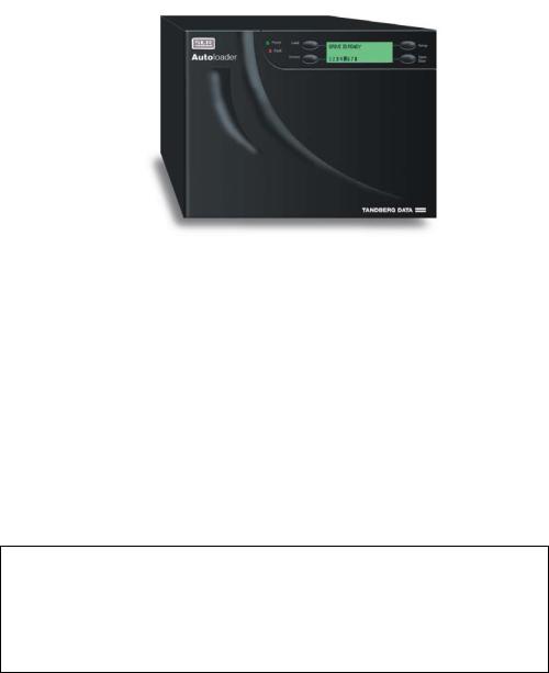
Tandberg Data’s SLR Autoloader is a compact tape cartridge loader designed for secure, reliable unattended system backup. Based on advanced Scalable Linear Recording (SLR) technology, the SLR Autoloader occupies only one half of the shelf space in a standard 19” rack yet delivers impressive storage capacity through its eight standard SLR data cartridges.
The tapedrive models SLR140, SLR100, SLR75 and SLR60 introduces Variable Rate Randomizer (VR2) technology. VR2 is an advanced data encoding method. VR2 improves code rate efficiency to more than 99% and can potentially double the capacity and performance of a drive.
The entire system is under host control via an industry standard SCSI interface. Its tape handling robotics are both rugged and simple for utmost reliability. The unit requires no preventive maintenance beyond cleaning the tape drive.
The key features of the SLR Autoloader include:
•Removable 8-cartridge magazine
•Integrated Bar Code Reader standard
•Locking front door under system control
•Low Voltage Differential (LVD) / Single-Ended (SE) Interface
•Auto Clean Mode
•On-board Diagnostics.
*** IMPORTANT ***
Review the READ ME FIRST caution at the beginning of
Chap. 2 before you power up the unit for the first time.
Tandberg SLR Autoloader Service and Repair Manual |
1 |

Tandberg Data |
Chapter 1 - Introduction |
Models
There are tree models of the SLR Autoloader. The model number for each is identical except for the last two/three digits which represent the maximum compressed data capacity gigabytes (GB) for each cartridge used in a particular model. See Tables 1-1 and 1-2 below.
For additional specification information, refer to Appendix A.
Capacity
|
SLR Autoloader Model |
Cartridge |
Cartridge |
Magazine |
Magazine |
|
|
Capacity |
Capacity |
Capacity |
Capacity |
|
|
|
|
|
||||
|
|
(Native) |
(Comp 2:1) |
(Native) |
(Comp 2:1) |
|
|
Tandberg 1108 SLR 60 1 |
30 GB |
60 GB |
240 GB |
480 GB |
|
|
Tandberg 1108 SLR 75 |
38 GB |
75 GB |
304 GB |
600 GB |
|
|
Tandberg 1108 SLR 100 |
50 GB |
100 GB |
400 GB |
800 GB |
|
|
Tandberg 1108 SLR 140 |
70 GB |
140 GB |
560 GB |
1,12 TB |
|
Table 1-1 |
|
|
Data Storage Capacity |
|||
Data Transfer Rates
|
SLR Model |
Maximum Sustained |
Maximum Sustained |
|
|
|
Rate, Native |
Rate, Compressed |
|
|
Tandberg 1108 SLR 60 1 |
4.0 MB/s |
8.0 MB/s |
|
|
|
14.4 GB/hr |
28.8 GB/hr |
|
|
Tandberg 1108 SLR 75 |
4.0 MB/s |
8.0 MB/s |
|
|
|
14,4 GB/hr |
28,8 GB/hr |
|
|
Tandberg 1108 SLR 100 |
5.0 MB/s |
10.0 MB/s |
|
|
|
18 GB/hr |
36.0 GB/hr |
|
|
Tandberg 1108 SLR 140 |
6.0 MB/s |
12.0 MB/s |
|
|
|
21,6 GB/hr |
43,2 GB/hr |
|
Table 1-2 |
|
Data Transfer Rates |
||
Note: The rates for compressed data are the native rates multiplied by the compression factor, which depends on file content, but averages approximately 2:1.
Note: GB/hour rates are maximum and may vary due to the specific characteristics of the data.
1 End of Life 2003
2 |
Tandberg SLR Autoloader Service and Repair Manual |

Media Compatibility
The SLR140, SLR100, SLR75 and SLR60 Autoloader models can perform the following operations with the indicated media
|
|
|
Drives |
|
|
|
|
Tape type |
SLR140 |
SLR100 |
|
SLR75 |
|
SLR60 |
|
SLRtape140 |
R/W |
- |
|
- |
|
- |
|
SLRtape100 |
R/W |
R/W |
|
- |
|
- |
|
SLRtape75 |
R/W |
R/W |
|
R/W |
|
- |
|
SLRtape60 |
R/W |
R/W |
|
R/W |
|
R/W |
|
SLRtape50 |
R/W |
R/W |
|
R/W |
|
R/W |
|
SLRtape40 |
R/W |
R/W |
|
R/W |
|
R/W |
|
SLRtape7 |
R |
R |
|
R |
|
R |
|
SLRTape32 2 |
- |
R |
|
R |
|
R |
|
SLRtape24 |
- |
R |
|
R |
|
R |
|
SLR5 |
- |
- |
|
R |
|
R |
|
Table 1-3 |
|
|
|
|
Media compatibility |
||
Product Description
The SLR Autoloader family of products includes several features designed to increase the ease of use and utility of the product. This includes a removable 8- cartridge magazine for easy management of data sets or archival storage. Menudriven operator control panel interface with backlit LCD providing easy control of configuration and diagnostic modes. Autoselecting AC input power for worldwide application. Interface support for Ultra2 SCSI (LVD) and standard FAST SCSI single-ended systems.
2 Includes 13 and 26 GB Media
Tandberg SLR Autoloader Service and Repair Manual |
3 |
Tandberg Data |
Chapter 1 - Introduction |
Front Panel
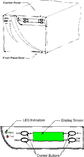
The Front Panel includes the User Control Panel with LCD display and Control Buttons, LED indicators, and the Front Door Panel.
Control Panel
The control panel presents:
•A backlit green LCD matrix display
•Four control buttons
•Two LED indicators (green and red/amber).
4 |
Tandberg SLR Autoloader Service and Repair Manual |
LCD Display
In various modes of operation, the display panel screens can show you:
•Drive and loader status
•Menu choices, and
•Error messages.
Through most of its operation, the backlit screen displays four 20-character lines of information. This manual refers to the four text lines of the screen as line 1 through line 4, moving from top to bottom. You can scroll some screens to greatly expand the amount of available information. A pointer symbol (θ) indicates additional options.
Control Buttons
The control buttons let you perform manual tape handling operations, configuration, and diagnostics:
•The Load button (top left) lets you load tapes from the magazine to the drive.
•The Unload button (lower left) lets you unload tapes from the drive and return them to the magazine.
•The Open Door button (lower right) releases the door latch after the completion of any in-process action and when the loader is idle.
•The Menu button (top right) lets you enter menu mode where you can select configuration options and perform unit diagnostics.
When you enter menu mode, the buttons are re-identified on the display screen to indicate the different functions they perform under alternate menu levels.
LED Indicators
The green Ready indicator illuminates when the unit is powered up and standing by to receive instructions. When you start a load, unload, or open door action, the Ready indicator goes out. The indicator remains illuminated as you enter menu mode and as you then access the system data. The loader will not remain in a ready state if you access any other area of the menu mode, and the indicator will then go out.
The red or amber Fault indicator illuminates when the unit experiences a mechanical fault in the drive or loader robotics. If such a fault occurs, refer to the Error Code tables in Chapter 6 – Troubleshooting. If that does not clear up the fault, contact your Technical Support Representative.
Tandberg SLR Autoloader Service and Repair Manual |
5 |
Tandberg Data |
Chapter 1 - Introduction |
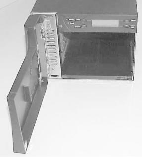
Front Panel Door
The door is opened by a control panel button, with the door latch being released by the Autoloader robotic mechanism. In order to operate the front door AC power must be applied. The hinged door swings open to the left, permitting access to the tape cartridge magazine.
While the door usually remains locked during normal operations, you can open it, even with a tape in the drive. If you try to open the door with a tape in the drive, the unit displays a warning message. You can unlock the door or cancel the operation.
6 |
Tandberg SLR Autoloader Service and Repair Manual |
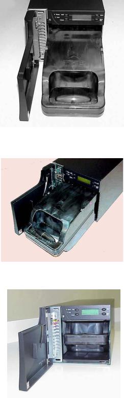
Tape Cartridge Magazine
The 8-cartridge magazine is accessible through the front panel door. The rugged polymer magazine fits into an alignment guide, which assures precise cartridge positioning with respect to the loader robotics.
The only correct insertion orientation for the magazine is shown in the photographic sequence on the next page.
As the magazine moves into its loader compartment, it should move inward until it snaps into place. (The two chassis metal detents snap into the magazine slots in its top surface). The magazine locks into position when you close the front door panel.
Note: The SLR Autoloader is shipped with a soft vinyl dust cover for use when the magazine is not installed in the loader unit. The cover is contained in the Accessories Kit box and can be easily slipped over the open end of the magazine.
The SLR Autoloader magazine is shown here:
Tandberg SLR Autoloader Service and Repair Manual |
7 |
Tandberg Data |
Chapter 1 - Introduction |
LOADING VIEW #1
FRONT VIEW
Proper alignment of magazine prior to loading it into its bay in the SLR Autoloader.
LOADING VIEW #2
DIAGONAL SIDE VIEW
Better view of the front end of the magazine entering its bay of SLR Autoloader.
LOADING VIEW #3
FRONT VIEW
View of magazine properly locked into detent position.
8 |
Tandberg SLR Autoloader Service and Repair Manual |
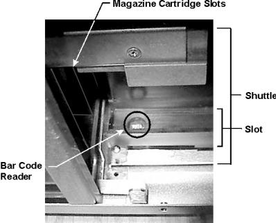
Bar Code Reader
An integrated bar code reader is installed as standard equipment in the SLR Autoloader. It is an integral part of the robot shuttle assembly and moves with it.
At power up, the loader automatically pulls each cartridge into the robot shuttle to scan the bar code, and replaces it in the magazine. If the magazine is full, then it takes approximately 150 seconds (in addition to the normal inventory / calibration time) to scan all cartridges, since one cartridge can be scanned in 9 seconds, then returned in equal time to its slot.
Usually hidden by the metal chassis, the bar code reader is located at the leading edge of the shuttle slot as shown in the following illustration:
Tandberg SLR Autoloader Service and Repair Manual |
9 |
Tandberg Data |
Chapter 1 - Introduction |
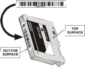
Bar Code Label
The bar code label is encoded with a Code 3 of 9 standard bar code format.
The label for all cartridges consists of six alphanumeric characters: three alpha characters and three numeric characters. The cleaning cartridge uses CLN as the alpha characters. For example:
Data cartridge |
ABC000 |
DEF123 |
|
Cleaning cartridge |
CLN000 |
CLN123 |
|
Note: You should enable the Enable Check Char option for the most reliable bar code reader function.
Position the label centrally on the cartridge spine with the six alphanumeric characters aligned with the cartridge’s base plate.
Ordering Bar Code Labels
You should order additional bar code labels directly from Tandberg Data. Tandberg bar code labels are made of a mirror-like substrate with special reflectivity, bar widths, and other characteristics.
Caution: Do not substitute any other bar code labels. They will be unreadable.
See Appendix B – Spares/Accessories for part number information.
10 |
Tandberg SLR Autoloader Service and Repair Manual |
Calibrating the Bar Code Reader
To calibrate the bar code reader, do the following:
1.Insert a cartridge in Slot 2 of the SLR Autoloader. Make sure the cartridge has a bar code label that is:
•Tandberg approved for SLR Autoloader
•Clean
•Properly positioned on the cartridge.
2.Power up the Autoloader.
3.Press and hold down the Menu button while you press and release the Load button.
4.Continue holding down the Menu button until the READY light turns off. This will take abt. 10 seconds.
5.From the DIAGNOSTICS menu, scroll down to and select Barcode Calibration.
The SLR Autoloader fetches the cartridge from Slot 2 and moves the cartridge back and forth across the bar code reader sensor.
It displays the upper and lower values as it progresses through the calibration and then displays one of the following:
•If the calibration passes
|
|
PASSED |
• |
If the calibration fails or is aborted |
ABORTED |
• |
If there is no cartridge in Slot 2 |
NO CARTRIDGE IN SLOT 2 |
6.If there is no cartridge in Slot 2, exit the DIAGNOSTICS MENU, open the door, place a cartridge in Slot 2, reinsert the magazine and start the procedure again from Step 3.
Tandberg SLR Autoloader Service and Repair Manual |
11 |
Tandberg Data |
Chapter 1 - Introduction |
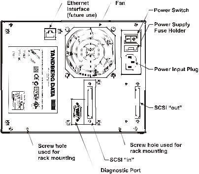
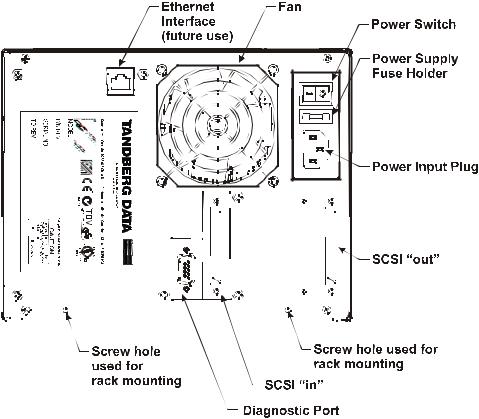
Rear Panel
The rear panel includes eight mechanical devices that relate to bus communication, firmware upgrading and troubleshooting, device cooling, and line power. Bus communication between the SCSI Bus connector and the Host adapter occurs through SCSI Bus connectors (see SCSI In and SCSI Out). The Diagnostic Port provides sequence information, diagnostic test results and firmware updates. Line power is supplied and monitored after its circuit is opened by the Power Input Plug, Power Supply Fuse (in its holder) and the Power Switch. The Product Information Label includes Model and Serial numbers and cautionary information.
Note: The two empty screw holes on the bottom of the panel are intended for use only if you mount the unit in a rack. If you have ordered the rack mount conversion kit, the appropriate fasteners used in this location are provided.
Integrated Cooling Fan
The rear panel contains a single forced-air cooling fan, which draws air inward through the front of the unit and expels it out the back. The fan prevents overheating of the drive and robotics electronics, the motors, and the power supply.
Since there is no air filter to clean on a regular basis, you should inspect occasionally for lint or dust buildup and vacuum the area if necessary.
12 |
Tandberg SLR Autoloader Service and Repair Manual |
Power Switch
The power switch is located on the upper right corner of the rear panel. It is a twoposition rocker switch that controls the supply of AC power to the unit:
•To turn the power ON, depress the switch on the 1 side. The LCD display illuminates.
•To turn the power OFF, depress the switch on the 0 side.
Power Supply
The auto ranging power supply will adjust to the operating voltage range supplied through the power cable. The nominal range is 110–240 VAC. The power supply is capable of operating at 50 or 60 Hz without modification. AC power from a properly grounded outlet is supplied through a line power cable shipped with the SLR Autoloader.
For more information on line power cables, see the Power Cable section of Chapter 2 – Installation.
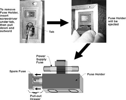
Power Supply Fuse Holder
The power supply fuse holder is located below the power switch as indicated by the outline diagram on its surface. The procedure for accessing power fuse (and its spare) is shown below.
Note: Before replacing the fuse, set the Main power switch to OFF and remove the power cord.
|
|
|
|
|
|
|
|
|
|
|
|
|
|
|
|
Tandberg SLR Autoloader Service and Repair Manual |
13 |
||||||
Tandberg Data |
Chapter 1 - Introduction |
SCSI Interface Connectors
The SCSI Interface connectors link the internal SCSI bus devices (SCSI drive and robotic controllers) to the external host adapter. The bi-directional SCSI bus transfers the SCSI commands and data. To provide this function, there are two 68pin, high density, shielded D-type SCSI Connectors which connect to shielded SCSI Type P cables. The pair of connectors allows for daisy chaining more than one SLR Autoloader to a host adapter or other SCSI-compatible device. When only one SCSI connector is used, the second connector must be terminated using the supplied LVD/SE dual mode terminator.
Ethernet Port
The Ethernet port is reserved for future use.
Diagnostic Port
The Diagnostic port (RS-232) is used to upload fault analysis data by the service technician after a fault condition occurs. It is also used to update the firmware in the controller card’s flash memory.
Embedded Diagnostics
•The SLR Autoloader includes three levels of diagnostics:
•The Power-On Self Test (POST) — Performs several verification and memory tests when you power on the unit.
•User Diagnostics — Lets you change setup options. Select from front panel.
•Tech Support Diagnostics — Used by Technical Support Engineers to diagnose faults and service the unit.
14 |
Tandberg SLR Autoloader Service and Repair Manual |
This Page Intentionally Left Blank
Tandberg SLR Autoloader Service and Repair Manual |
15 |

Chapter 2 – Installation
*** READ ME FIRST ***
Tandberg Data has installed a locking pin as a precautionary safety mechanism to prevent damage to the SLR Autoloader during shipment from the factory. Inserted from underneath the loader floor, the pin prohibits any lateral movement of the shuttle assembly by locking it down.
CAUTION!
You must remove the Shuttle Locking Pin
before powering up the unit or it will not operate.
See the procedure on the following pages.
Carefully unpack the unit from the shipping container. Save the container and packing materials in case you need to return the unit to Tandberg Data for repairs.
Review the contents of the shipping container to be sure that all parts were included in the shipment. A complete package for the SLR Autoloader consists of the following items:
•A factory-assembled SLR Autoloader unit (black or gray metal box) containing one cartridge magazine.
Note: The SLR Autoloader contains no cartridges prior to shipment.
•An Accessory Kit Box containing:
1 The Tandberg Recource CD containing this manual.1 Warranty/Registration Card
2 Line Power Cords: one for USA, one for European power outlets1 Data Cartridge
1 Cleaning Cartridge1 SCSI Interface Cable
1 68-pin LVD/SE Terminator.1 Magazine Dust Cover
Note: If you haven’t done so, remove the locking pin from the SLR Autoloader.
Tandberg SLR Autoloader Service and Repair Manual |
16 |
Tandberg Data |
Chapter 2 - Installation |
Removing the Locking Pin
To remove the locking pin (also called lockdown mechanism), do the following:
1.Make sure that the power cord is disconnected from line power.
2.Place the unit on a table at waist height.
3.Position the unit so that the front panel door is facing toward you.
4.Rotate the unit onto its left side so that the bottom of the unit faces right and its rear chassis end points away from you.
5.Remove the screw from the locking pin as shown in the following illustration:
Right Side View with
Chassis Panel
Removed
Locking Pin (Installed)
6. Pull the locking pin out slowly. It should comeScrewout easily. If it doesn’t,
Metal Tab on Locking Pin
Right Side View, Rotated 45°
Upward with Chassis Panel
Removed
remove the magazine and investigate the internal shuttle area through the front panel door with a flashlight. (See Appendix C for instructions on opening the door without power.) Make sure that the pin is not bent. If it is, contact Tandberg Data for instructions on removing the pin or returning the unit to Tandberg Data for repair or replacement.
7.Save the locking pin (6.6” / 16.8 cm) and its screw (M3x8 Phillips panhead) in case you must return the unit to Tandberg Data. These two parts must be installed when shipping the unit back to Tandberg Data.
Tandberg SLR Autoloader Service and Repair Manual |
17 |
Reinstalling the Locking Pin
Note: The locking pin must be reinstalled to prevent damage to the cartridge shuttle mechanism during transportation.
1.Make sure that the power cord is disconnected from line power.
2.Make sure the shuttle is parked in the home position. (See the description of the Utilities menu on page xx)
3.Place the unit on a table at waist height.
4.Position the unit so that the front panel door is facing toward you.
5.Rotate the unit onto its left side so that the bottom of the unit faces right and its rear chassis end points away from you.
6.Remove the magazine to have a better view of the internal shuttle area.
7.Push the locking pin in slowly through the hole on the bottom (now facing right) through to the hole in the metal rack plate on the top side (facing left). If you have trouble with this, put your hand inside the shuttle area to guide the pin.
8.Insert and tighten the screw (M3x8 Phillips panhead).
Installation Procedure
After removing the locking pin and confirming that all package items are present in the shipment, proceed with the installation procedure.
1.Mounting—Proper placement of a tabletop unit or mechanical installation into a 19” rack.
2.Cabling—Connecting the unit to AC power and to the host interface and terminating the buses properly.
3.Software Installation.
Tandberg SLR Autoloader Service and Repair Manual |
18 |
Tandberg Data |
Chapter 2 - Installation |
Mounting Tabletop Units
Tabletop units require no mechanical assembly. Place the unit on a desk, table, server top, or other stable, horizontal surface with at least 2-inch (5 cm) clearance behind it to allow free flow of cooling air from the fan.
CAUTION: Make sure the Autoloader stays in a horizontal position while operating. Do not operate it on its side.
Mounting Rack Units
The compact size of the SLR Autoloader permits the mounting of up to two units in a single shelf of a standard 19” rack. Both units attach to a rack chassis. The units are secured to the rack chassis by rear brackets and fastened in place by two machine screws. The chassis and both units fit within a 4U rack height.
Note: Before mounting the SLR Autoloader(s), you must order a separate hardware kit for converting the unit(s) from a tabletop to a rack mounted one.
Rackmount Installation Process
1.Add the rack chassis to the rack frame.
2.Fasten one or two SLR Autoloader chassis to the installed rack chassis.
Tandberg SLR Autoloader Service and Repair Manual |
19 |
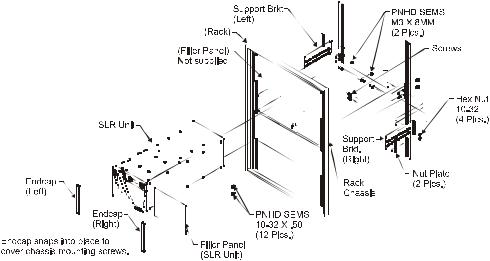
Installation of SLR Autoloader Rack Chassis into Rack
1.Attach the left support bracket to the left rear rail surface side using two 1032x1/2” screws and two 10-32 nut plates.
2.Attach the right support bracket to the right rear rail surface side using two 1032x1/2 screws and two 10-32 nut plates.
3.Attach the front chassis to the inside surface of the front rack rail using four 1032x1/2 screws (two for each side).
4.Attach the left and right bracket(s) to the outside rear chassis surface using four 10-32x1/2 screws and four10-32 hex nuts (two screws and two hex nuts on each side).
5.Attach left endcap to outside surface of left front rail by snapping a ball stud into a retaining clip located on the front chassis mounting flange.
6.Repeat Step 5 for the right endcap.
The rack chassis is now ready to mount the SLR Autoloader unit(s).
Installation of SLR Autoloader(s)
To install a single SLR Autoloader:
1.Attach to either the left or right side: the front filler panel to the chassis using two screws (M3 x 6mm).
2.Prepare the unit before installation:
•Remove the four screws and four rubber feet from the bottom panel of the unit
•Remove the SLR Autoloader chassis cover by sliding it rearward.
3.Insert the prepared SLR Autoloader unit into the rack chassis until it is stopped by the rear-mounting bracket.
4.Secure the unit to this bracket using two screws (M3 x 8 mm).
To install two SLR Autoloaders:
1.Prepare both units as described in Step 2 for installing a single unit.
2.Insert both units into the chassis until they are stopped by the rear mounting brackets.
3.Secure each unit to its mounting bracket using two screws (M3 x 8mm).
Tandberg SLR Autoloader Service and Repair Manual |
20 |
Tandberg Data |
Chapter 2 - Installation |
Cabling and Interface Connections
Before the SLR Autoloader can be powered up or communicate with the host device or user applications, the following connections must be made (see the diagram of the rear panel’s connectors on the next page):
•AC line power
•Select and connect the proper line power cable (from the pair of power cables sent in the Accessory Kit shipped with the SLR Autoloader) between the Power Input Plug (see the illustration below) and your line power outlet.
•SCSI bus connection to the host (68 pin LVD or SE).
•Connect the SCSI Cable between the SCSI Out connector of the Host Adapter to the SCSI In connector of the SLR Autoloader. If the SLR Autoloader is not being daisy-chained to another device, then connect the supplied LVD/SE Terminator to the SCSI Out connector.
Power Cable
The power cable is a standard grounding AC cable, which plugs a 3-wire connector into the rear panel and the other end has a country-specific connector plug that fits into a reliably grounded AC outlet.
|
|
|
|
|
|
|
|
|
|
|
|
|
|
|
|
|
|
|
|
|
|
|
|
|
|
|
|
|
|
|
|
|
|
|
|
|
|
|
|
|
|
|
|
|
|
|
|
|
|
|
|
|
|
|
|
|
|
|
|
|
|
|
|
|
|
|
|
|
|
|
|
|
|
|
|
|
|
|
|
|
|
|
|
|
|
|
|
|
|
|
|
|
|
|
|
|
|
|
|
|
|
|
|
|
|
|
|
|
|
|
|
|
|
|
|
|
|
|
|
|
|
|
|
|
|
|
|
|
|
|
|
|
|
|
|
|
|
|
|
|
|
|
|
|
|
|
|
|
|
|
|
|
|
|
|
|
|
|
|
|
|
|
|
|
|
|
|
|
|
|
|
|
|
|
|
|
|
|
|
|
|
|
|
|
|
|
|
|
|
|
|
|
|
|
|
|
|
|
|
|
|
|
|
|
|
|
|
|
|
|
|
|
|
|
|
|
|
|
|
|
|
|
|
|
|
|
|
|
|
|
|
|
|
|
|
|
|
|
|
|
|
|
|
|
|
|
|
|
|
|
|
|
|
|
|
|
|
|
|
|
|
|
|
|
|
|
|
|
|
|
|
|
|
|
|
|
|
|
|
|
|
|
|
|
|
|
|
|
|
|
|
|
|
|
|
|
|
|
|
|
|
|
|
|
|
|
|
|
|
|
|
|
|
|
|
|
|
|
|
|
|
|
|
|
|
|
|
|
|
|
|
|
|
|
|
|
|
|
|
|
|
|
|
|
|
|
|
|
|
|
|
|
|
|
|
|
|
|
|
|
|
|
|
|
|
|
|
|
|
|
|
|
|
|
|
|
|
|
|
|
|
|
|
|
|
|
|
|
|
|
|
|
|
|
|
|
|
|
|
|
|
|
|
|
|
|
|
|
|
|
|
|
|
|
|
|
|
|
|
|
|
|
|
|
|
|
|
|
Tandberg SLR Autoloader Service and Repair Manual |
21 |
|||||||||||||||||||||||||||||||
There are two types of power cables supplied with the SLR Autoloader. They differ in their cable connectors and length. Each cable has a different terminal ending for connecting to local line power. The cable length of the USA version is 6.5 feet (2.0 m); the European one is 2.5 m.
To maintain product safety compliance, select the power cord with a suitable electrical rating that is approved for the country where the product is used. In the USA, use a UL listed cord; in Canada, a CSA certified cord; and in Europe, use a Harmonized cord marked <HAR> or a nationally certified cord.
Note: After connecting the SLR Autoloader to your AC source, it is a good practice to do a test power up of the unit before connecting to the host computer. This will verify proper initialization and electrical behavior and isolate unexpected conditions to the host interface. The affirmation that the system is operating properly is the appearance of the cartridge map on the display panel, along with the green Ready LED being lit. (See the beginning of Chapter 3 – Operation for an example of a cartridge map on the display panel.) Power down the unit before connecting to the host.
Interfaces
The SLR Autoloader is supplied with both single-ended Fast/Wide and LVD Ultra 2 SCSI interfaces. The unit configures automatically to either interface.
The Fast/Wide SCSI interface uses high-density 68-pin connectors. Fast/Wide SCSI cables and terminators are secured to the connectors by jackscrews.
The drive and the robotics are separate SCSI devices. They require unique SCSI address because they are daisy-chained on the same bus. The SCSI addresses of the robotics and drive may be set from the control panel.
In order to connect the unit to a host computer system, the host system must have a compatible SCSI controller and the appropriate driver software. Call your Technical Support representative if you have any questions about installing for specific host systems.
Tandberg SLR Autoloader Service and Repair Manual |
22 |
Tandberg Data |
Chapter 2 - Installation |
Interface Cable Specifications
The SLR Autoloader is a high-performance system. To avoid degradation of performance, any additional or replacement cables you use should likewise be of the highest quality. The detailed requirements for SCSI cables are set forth in ANSI X3.131-1994. All SCSI cables used with the SLR Autoloader should meet the following requirements:
•Shielded or double-shielded, as required to meet EMI specifications
•Nominal characteristic impedance is 90 single-ended and 132 ohms differential
•Cables of different impedance should not be used together
•Maximum cable lengths as follows:
|
SE/Fast/Wide Bus |
|
LVD Fast Ultra 2 Bus |
|
||||
|
|
To Host |
|
Total |
Internal |
To Host |
|
Total |
5 ft |
|
4.8 ft |
|
9.8 ft |
5 ft |
34.4 ft |
|
39.4 ft |
1.54 m |
|
1.46 m |
|
3 m |
1.54 m |
10.46 m |
|
12 m |
Note: This equipment has been tested for electromagnetic emissions and immunity using good quality shielded cables. The use of unshielded cables, poor quality cables or other variances from good practice may result in non-compliance with national and international rules and degraded performance.
Interface Cable and Terminator Installation
An LVD/SE terminator is supplied with your unit, packaged in the accessory kit bag.
This terminator must be installed onto the device used at either end of a SCSI bus, such as the first or last device along a daisy-chain, or as a single SCSI peripheral. Usually, the host computer’s SCSI interface is at one end of the bus and terminated, so the question is whether the SLR Autoloader or another device is the last device on the bus.
On the rear panel of the unit, the incoming SCSI bus is connected to the left SCSI connector and the terminator or the outgoing SCSI bus is connected to the right SCSI connector (see the illustration on the next page).
To properly cable the drive, do the following:
1.Make sure the unit and the host computer are powered down.
2.Make sure that your host system has appropriate SCSI interface card or cards and software drivers installed. The interface card should use Fast/Wide or Ultra/Wide SCSI, single-ended or low voltage differential (LVD). All models of the SLR Autoloader are equipped with a LVD/SE Wide SCSI interface. Be sure to use the same type of SCSI hardware consistently throughout your configuration.
3.Use only the SCSI terminator supplied with the SLR Autoloader. It should be one of two available models — either with or without an LED indicator light. See the following illustration.
Tandberg SLR Autoloader Service and Repair Manual |
23 |

68-Pin High Density Male Connector |
|
LED Light |
Thumb Screw Pole |
4.If the SLR Autoloader is the only SCSI
SCSI device you want to connect to the interface card, connect the cable
  from
from the
the  interface card to the incoming SCSI connector, attach the terminator to the outgoing SCSI connector, then skip to step 6.
5.If you have two or more additional SCSI devices to connect to the interface card, your SLR Autoloader must be connected in daisy-chain fashion. That means that the cable from the interface card must be connected to the incoming SCSI connector of the first SCSI device, the cable from the outgoing connector of the first device must be connected to the incoming connector of the second SCSI device, and so on. You can connect them in any order. The terminator must be attached to the outgoing SCSI connector of the last device in the chain.
6.Make sure that each cable you use meets the specifications listed earlier in this chapter.
Tandberg SLR Autoloader Service and Repair Manual |
24 |
 Loading...