

Page 1
1
MXP Series Video Endpoints
User Guide
D1479201 MXP Serie s User Guid e, May 2011.
© 2010-2011 Cisco Sy stems, Inc. A ll right s reserv ed.
MXP Series Video Endpoints
User Guide
Thank you for choosing TANDBERG!
TANDBERG video conferencing oers the
natural communication experience of a
face-to–face meeting in ways that other
technologies cannot.
Your TANDBERG MXP video endpoint has
been designed to give you many years of
safe, reliable operation.
This user guide has been divided into
several chapters, all of which provide
dierent information. You can access the
chapters directly by clicking on the menu
bar at the top of this page.
You will nd that some places information
has been copied from other chapters (but
adapted, when needed) to let you have all
the relevant information there and then.
This helps eliminating the need to read
through long sections before you can even
think of getting started.
Software version F8.x
M a y 20 11
www.cisco.com
Page 2

Hidden text anchor for ToC
2
MXP Series Video Endpoints
User Guide
D1479201 MXP Serie s User Guid e, May 2011.
© 2010-2011 Cisco Sy stems, Inc. A ll right s reserv ed.
What’s in this user guide?
Getting started
Waking up the system ..................................................... 5
Pick up the remote control .......................................... 5
Even incoming calls wake up the system! ................... 5
If the system fails to respond ....................................... 5
The welcome screen ................................................... 5
The remote control (I) ...................................................... 6
The remote control (II) ..................................................... 7
Navigating in the menus .................................................. 8
Entering text in text elds ................................................ 9
The need for text ......................................................... 9
When number keys are pressed.................................. 9
Using number keys in text elds .................................. 9
Terminology used .......................................................... 10
Point-to–point vs. MultiSite ........................................ 10
MultiSite and Multiway calls ....................................... 10
About near end and far end ....................................... 10
Dual video stream ...................................................... 10
Selfview and camera control ..........................................11
What is Self view? .......................................................11
Using Selfview outside calls.......................................11
Selfview and Point-to–point ........................................ 11
Point-to–point and dual stream ...................................11
Controlling the camera ...............................................11
Controlling cameras at both ends...............................11
Dening camera presets ................................................12
Storing camera presets as 0–9… ................................12
Storing camera presets as any number 0–14… ...........12
Using the screen as PC display ......................................13
Use as PC screen .......................................................13
Picture in Picture (PIP) ................................................13
Picture outside Picture (POP) .....................................13
Standby ..........................................................................14
About standby.............................................................14
Leaving standby mode ...............................................14
Entering standby mode ...............................................14
The icons on the screen ................................................ 15
Making calls
Access codes .................................................................17
When the system asks for codes ...............................17
To make a call dialing the number ................................. 18
Making a call .............................................................. 18
Video vs. telephone calls ........................................... 18
Altering call settings before calling ............................... 19
About call settings ..................................................... 19
Making calls using the phone book ............................... 20
Ending an ongoing call .................................................. 21
Ending conference calls ............................................. 21
Ending point-to–point calls ......................................... 21
Ending MultiSite calls ................................................. 21
Answering an incoming call ........................................... 22
About incoming calls and privacy .............................. 22
Want a dierent ring tone? ........................................ 22
When someone calls you… ........................................ 22
Using the Do Not Disturb feature .................................. 23
Streaming ...................................................................... 24
Streaming settings ..................................................... 24
Setting up for streaming… .......................................... 24
Viewing the streamed content ................................... 25
Streaming a video meeting… ..................................... 25
Calling two others at the same time .............................. 26
Calling two others simultaneously … .......................... 26
Consultative transferring of calls ................................... 27
Transferring calls … .................................................... 27
Unattended transferring of calls .................................... 28
Transferring calls … .................................................... 28
About video conferences .............................................. 29
Using phone book group entries ............................... 29
IP and ISDN communication ...................................... 29
How many participants?............................................. 29
Conference calls … .................................................... 29
The MultiSite feature .................................................. 30
The Multiway feature ................................................. 30
Using phone book group entries ............................... 30
Adding calls to a conference… ................................... 30
Phone book usage
Basic phone book features ............................................ 32
Navigating in the phone book .................................... 32
Entering the phone book… ......................................... 32
Calling an entry .......................................................... 32
Searching the phone book ............................................ 33
Entering text in the search eld ................................. 33
Searching the phone book… ...................................... 33
Adding new contacts ..................................................... 34
Adding a new contact from the call log ..................... 34
Copying from the corporate phone book .................. 34
Adding a new contact from scratch… ........................ 34
Editing existing entries................................................... 35
Discarding an entry .................................................... 35
Editing an entr y… ........................................................ 35
Creating MultiSite entries .............................................. 36
About Multisite and Multisite entries .......................... 36
Observe the following: ............................................... 37
Editing and deleting MultiSite entries ............................ 38
Edit a MultiSite entry .................................................. 38
Deleting a MultiSite entr y ........................................... 38
To edit the participants of a group … ......................... 38
www.cisco.com
Page 3

3
MXP Series Video Endpoints
User Guide
D1479201 MXP Serie s User Guid e, May 2011.
© 2010-2011 Cisco Sy stems, Inc. A ll right s reserv ed.
What’s in this user guide?
In-call features
Using camera control .................................................... 40
Using far end camera control .................................... 40
Using near end camera control ................................. 40
Using camera presets ....................................................41
Using far end presets .................................................41
Using near end presets ..............................................41
Running presentations ................................................... 42
Use dual video stream if possible .............................. 42
Not all system have all choices .................................. 42
Running a presentation .............................................. 42
If you need to specify the presentation source… ....... 42
Dual Video Stream ......................................................... 43
No dual video stream? ............................................... 43
Dual stream and bandwidth .......................................43
Utilizing dual video stream ......................................... 43
Snapshots ...................................................................... 44
Taking a snapshot using the remote control .............. 44
Taking a snapshot using the menu… .......................... 44
Displaying a snapshot… .............................................. 44
Controlling far end video sources ................................. 45
Accessing far end video sources .............................. 45
Not all system have all choices .................................. 45
Far end video source options… .................................. 45
What is VNC used for? .............................................. 45
Text chatting in video calls ............................................ 46
Using the number keys in text elds .......................... 46
Chatting with the other party… ................................... 46
Video conferencing
About video conferencing ............................................. 48
Who becomes the host? ...........................................48
Request, release, and assign oor ............................ 48
Split screen & voice switching ................................... 48
Layout ........................................................................ 48
Request and release oor ............................................. 49
Assigning oor ........................................................... 49
Automated jumping to full screen .............................. 49
Requesting and releasing oor… ................................ 49
Assigning oor… ......................................................... 49
Layout ............................................................................ 50
The layout options available....................................... 50
Setting the display layout ........................................... 50
Terminal names ..............................................................51
Displaying terminal names…........................................51
www.cisco.com
Page 4
4
MXP Series Video Endpoints
User Guide
D1479201 MXP Serie s User Guid e, May 2011.
© 2010-2011 Cisco Sy stems, Inc. A ll right s reserv ed.
Chapter 1
Getting started
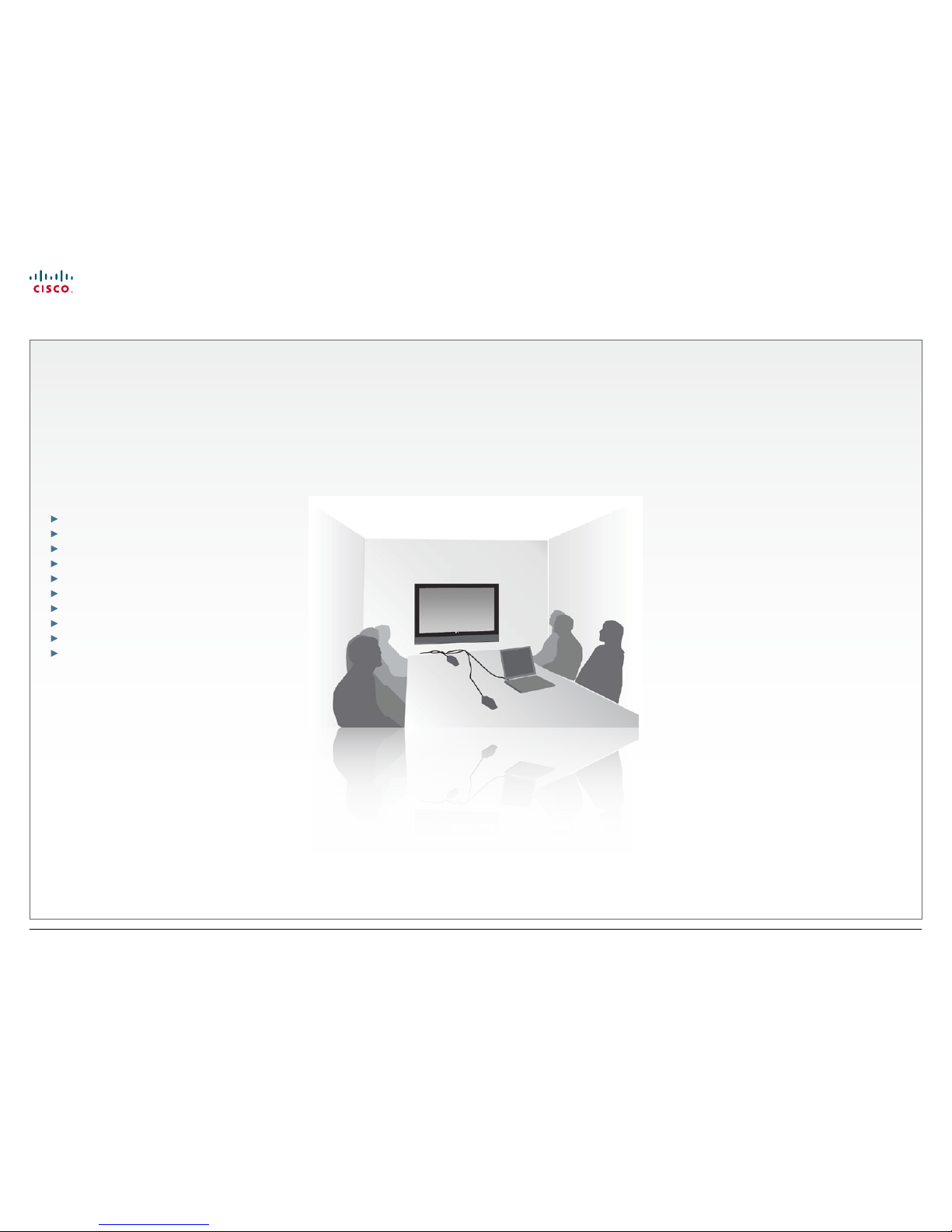
In this chapter…
Waking up the system
The remote control (I)
Navigating in the menus
Entering text in text elds
Terminology used
Selfview and camera control
Dening camera presets
Using the screen as PC display
Standby
The icons on the screen
www.cisco.com
Page 5
5
MXP Series Video Endpoints
User Guide
D1479201 MXP Serie s User Guid e, May 2011.
© 2010-2011 Cisco Sy stems, Inc. A ll right s reserv ed.
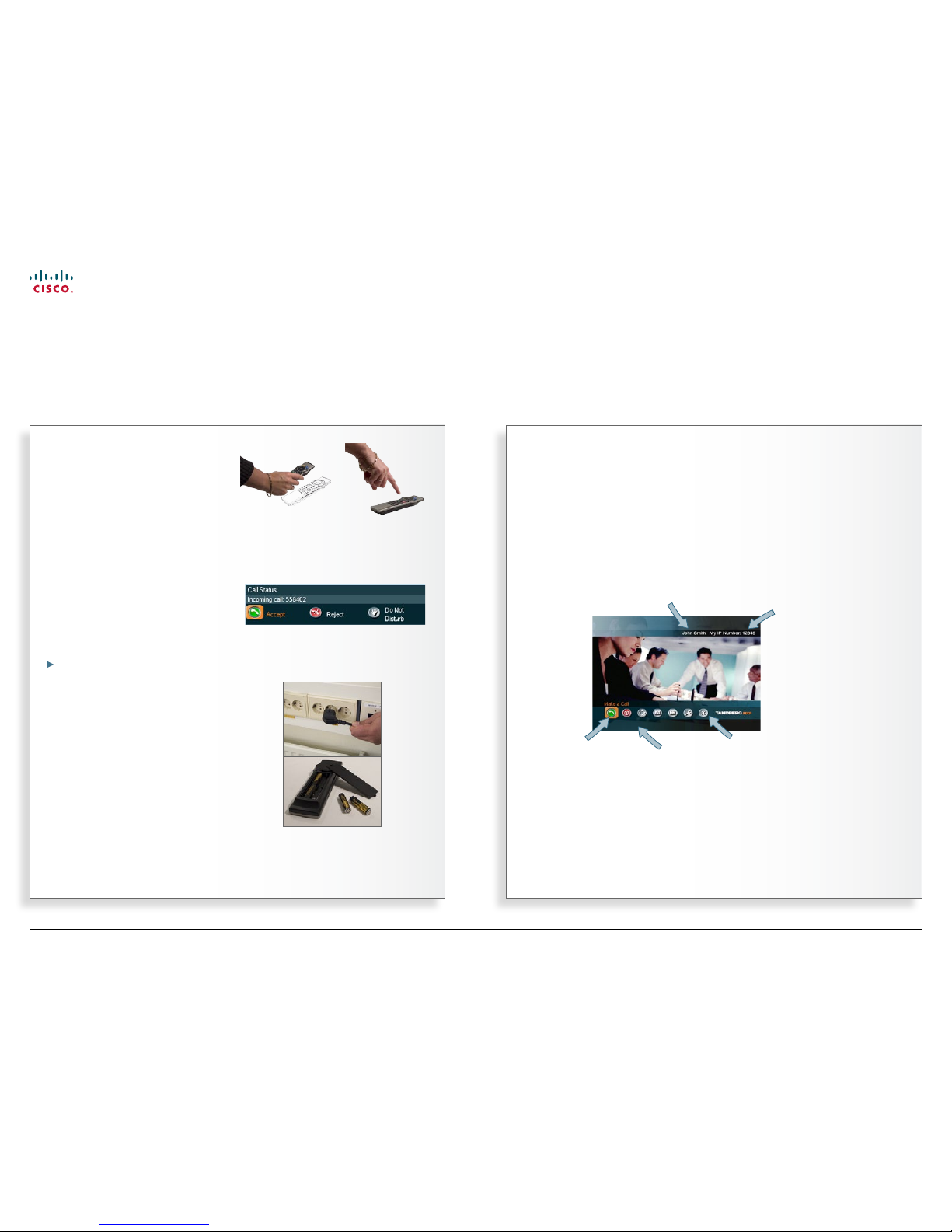
Pick up the remote control
To wake up the system just pick up the
remote control or press any key. You
may have to point the remote control
towards the system to make it discover
you.
The system will now show the welcome
screen.
Even incoming calls wake up the
system!
The system is in standby mode
whenever it is not used. The screen is
then black. A ny incoming call will wake
up the system from standby.
There are some restrictions to this if the
Using Do not disturb function has
been activated.
If the system fails to respond
Should the system fail to respond, make
sure that:
• The system is connected to line voltage
• The remote control has working batter-
ies.
The welcome screen
Waking up the system
To make a call you need to wake up the system from standby
The name that your
system has been given.
The IP number of
your system is the
dial-in number of
your system.
The main menu.
The orange frame
shows which icon is
currently selected.
Any calls missing or
other warnings will
appear here.
www.cisco.com
Page 6
6
MXP Series Video Endpoints
User Guide
D1479201 MXP Serie s User Guid e, May 2011.
© 2010-2011 Cisco Sy stems, Inc. A ll right s reserv ed.
THE REMOTE CONTROL THE UPPER PART
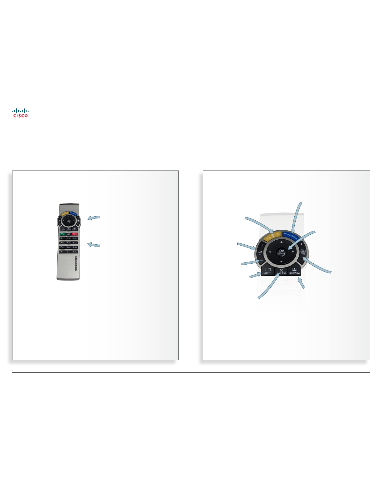
The remote control (I)
Don’t let the number of keys on the remote control confuse you. The system is quite simple
The upper part of
the remote control
is used to handle
the video part of
the call...
...while the lower
part of the remote
control resembles
very much the
keypad of a mobile
phone.
Switch to a predened
presentation source. If the
key is held down for 1 second
then the Presentation video
sources menu will appear.
Turn your
microphone on
an d o.
Adjust the
volume.
Zoom the
camera in
and out.
Toggle between full
screen and dierent
display layouts.
Display your outgoing
video. Press again to
return.
Takes you back
one step in the
menu system,
i.e. to leave a
menu undoing
any changes. Use
the key to delete
characters in an
input eld. Press
and hold the key
for 1 second to
close the menu.
Arrow keys are
used to navigate
in the menus.
Press OK to
show the menu
and to select
menu items.
Mute an
incoming call.
www.cisco.com
Page 7
7
MXP Series Video Endpoints
User Guide
D1479201 MXP Serie s User Guid e, May 2011.
© 2010-2011 Cisco Sy stems, Inc. A ll right s reserv ed.
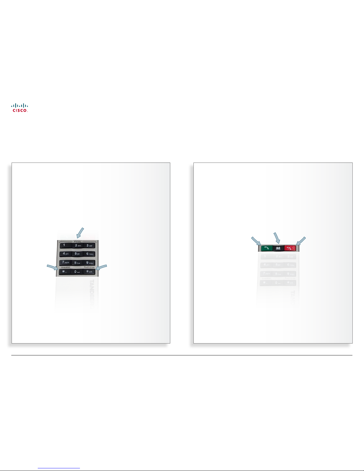
THE NUMERICAL KEYPAD THE CALL C ONTROL KEYS
Press To uc h
tones when
you are in a call
and need to
dial extension
numbers etc.
Press the OK
button to exit
Touch tones.
Take a
snapshot, but
only during a
call.
You may predene camera positions to
be used during a call. Presets do not
apply to systems with xed or manually
moved cameras.
Use the End
Call key
to end the
current call.
Pressing this
key when
not in a call
will put the
system in
Standby
mode.
Press the
Call key to
place a call.
Use the Phone
Book to store and
recall video contacts
for easy placement
of calls.
The remote control (II)
Don’t let the number of keys on the remote control confuse you. The system is quite simple
www.cisco.com
Page 8
8
MXP Series Video Endpoints
User Guide
D1479201 MXP Serie s User Guid e, May 2011.
© 2010-2011 Cisco Sy stems, Inc. A ll right s reserv ed.
SUBMENUS
GOING FURTHER DOWN IN THE HIERARCHY
RADIO BUTTONS
RESTORE DEFAULTS
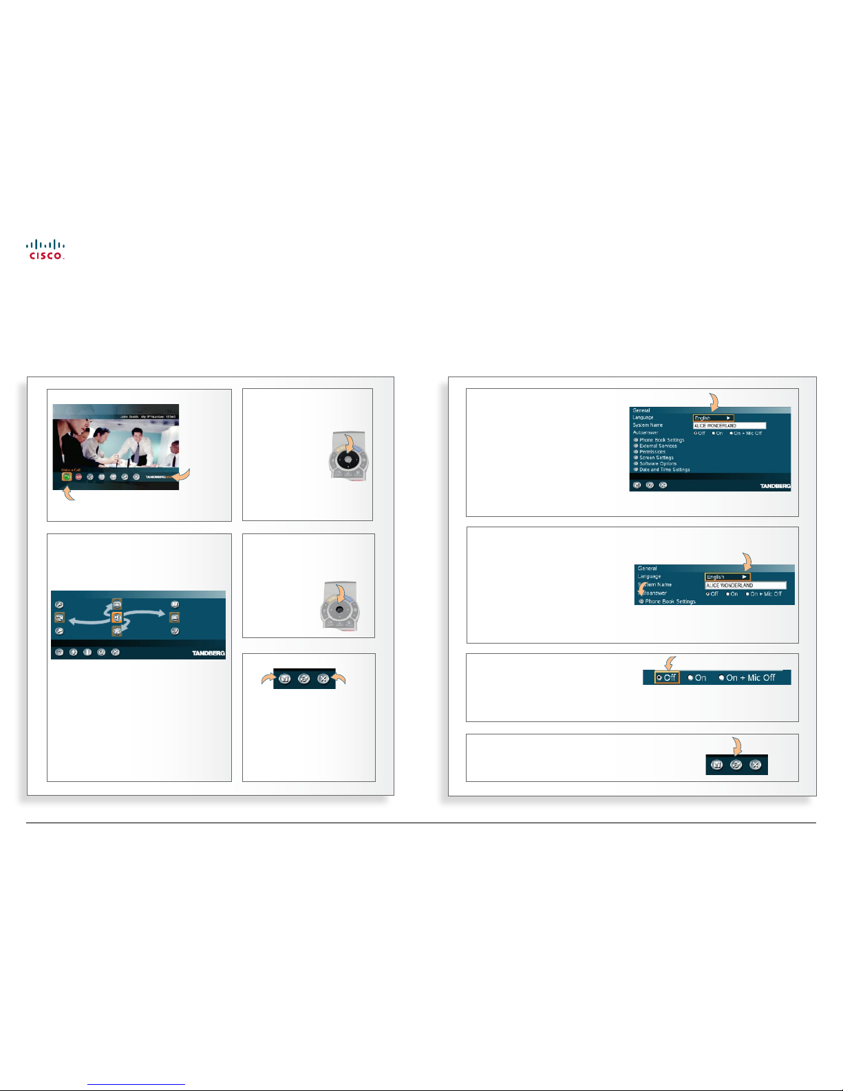
Navigating in the menus
Your TANDBERG system is operated by means of the remote control and a few basic navigation principles
All menu items having an arrow
appended allow you to go fur ther
down the hierarchy and enter
another submenu.
Press the OK key to go fur ther down
in the hierarchy.
Once you have navigated to a topic
of interest, press OK to select
that topic. You will then enter the
corresponding submenu.
The cursor position (the menu item
selected) is again indicated by an
orange frame.
Some choices consist of radio
buttons. Use the Arrow keys to
navigate and press OK to select a
setting.
Restore default. Select this icon and click OK
to restore default settings.
NAVIGATE IN THE MENU
ENTERING SUBMENU
The OK key is used to enter
the submenu of an icon.
Moving about the menu using the Arrow
keys.
THE ARR OW KEYS
Use the four
Arrow keys
to navigate
between icons
in a menu.
LEAVING A MENU
Cancel. Select
this icon and
click OK to
leave menu
undoing any
changes.
Save. Select
this icon
and press
OK to leave
menu putting
changes into
eect.
THE MAIN MENU
This is
called
the main
menu.
The orange frame indicates the icon
currently selected.
www.cisco.com
Page 9
9
MXP Series Video Endpoints
User Guide
D1479201 MXP Serie s User Guid e, May 2011.
© 2010-2011 Cisco Sy stems, Inc. A ll right s reserv ed.
Entering text in text elds
Some menu elds expect text information to be entered
Using number keys in text elds
Whenever text entries are expected
by the system, a small abc or ABC
appears in the right lower corner of the
entry eld. For entry elds expecting
numbers, 12 3 will appear instead. In
text mode, entries from the number
keys are automatically interpreted as
text entries in the same way as on a
cellular phone.
Guidelines:
• Press the key that corresponds to the
required letter as many times as needed
to produce that letter.
• Switch between lower case (abc) and
upper case (ABC) letters with the # a/A
key.
• Switch between text mode (abc) and
number mode (123) by keeping the
# a/A key depressed for more than a
second.
• To insert space, press the 0
key.
• To insert the @ sign, press the 1-key
twice, while the keypad is in text mode.
• To insert the . sign, press the
*
.-key
once, while the keypad is in number
mode.
• To write digits and numbers in a text
input eld, repeatedly press the corresponding key until the digit appears.
Example: How do I write A li c e 123
in the Search input eld in the phone
book?
Do as follows:
1. Press the 2-key once to get an A.
2. Press the #-key once to switch between
upper case and lower case letters.
3. Press the 5-key three times to get an l.
4. Press the 4-key three times to get an i.
5. Press the 2-key three times to get a c.
6. Press the 3-key twice to get an e.
7. Press the 0-key once to get space.
8. Press the 1-key three times to get a 1.
9. Press the 2-key four times to get a 2.
10. Press the 3-key four times to get
a 3.
The need for text
Apart from the need to enter the
number or identity of the person you
want to call, you will also—among other
things—need this ability to search and
maintain your list of contacts in the
phone book.
When number keys are pressed
• Pressing a number key outside calls will
produce the Call menu.
• Once positioned inside an entry eld
expecting text entries, the system automatically switches to text mode (ABC).
Entering letters is similar to as on a cellular phone—see right.
• Once positioned inside an entry eld
requiring number entries, the system
automatically switches to 123 mode
allowing numbers to be dialed with the
number keys as usual.
The type of entry expected is shown
here as either abc, ABC or 123.
Key in the letters using the lower part of
the remote control. Use the Cancel key
to erase incorrect inputs.
Al ice 12 3
Alic
Press the OK key or navigate down to
the OK icon and press OK to leave the
menu, putting changes into eect.
Press the Cancel key or navigate down
to Cancel and press OK to leave the
menu undoing any changes.
www.cisco.com
Page 10
10
MXP Series Video Endpoints
User Guide
D1479201 MXP Serie s User Guid e, May 2011.
© 2010-2011 Cisco Sy stems, Inc. A ll right s reserv ed.
Dual video stream
Your video system supports the use of
dual video streams in video meetings.
This means that you can transmit and
receive things like PC presentations and
DVD footage during the video meeting
(point-to–point as well as conferences),
in addition to the usual video signal you
receive and transmit. Dual video stream
is an optional feature.
The wonder ful thing about this is that
it opens up for presentations of things
made with tools that require PCsoftware only used by specialists.
One example could be the results of
geological surveys in the oil business.
A survey result presentation can be
important for crucial decision making,
but how do you show this to people
located thousands of miles apart?
The answer is simple; hook up your PC
to the video system, set it up for dual
video stream and give your presentation
as the second video stream!
Details about dual video stream usage
can be found in the article
Utilizing
dual video stream.
The exact look of the screen dur ing
a dual video stream session is
determined by the
Setting the display
layout.
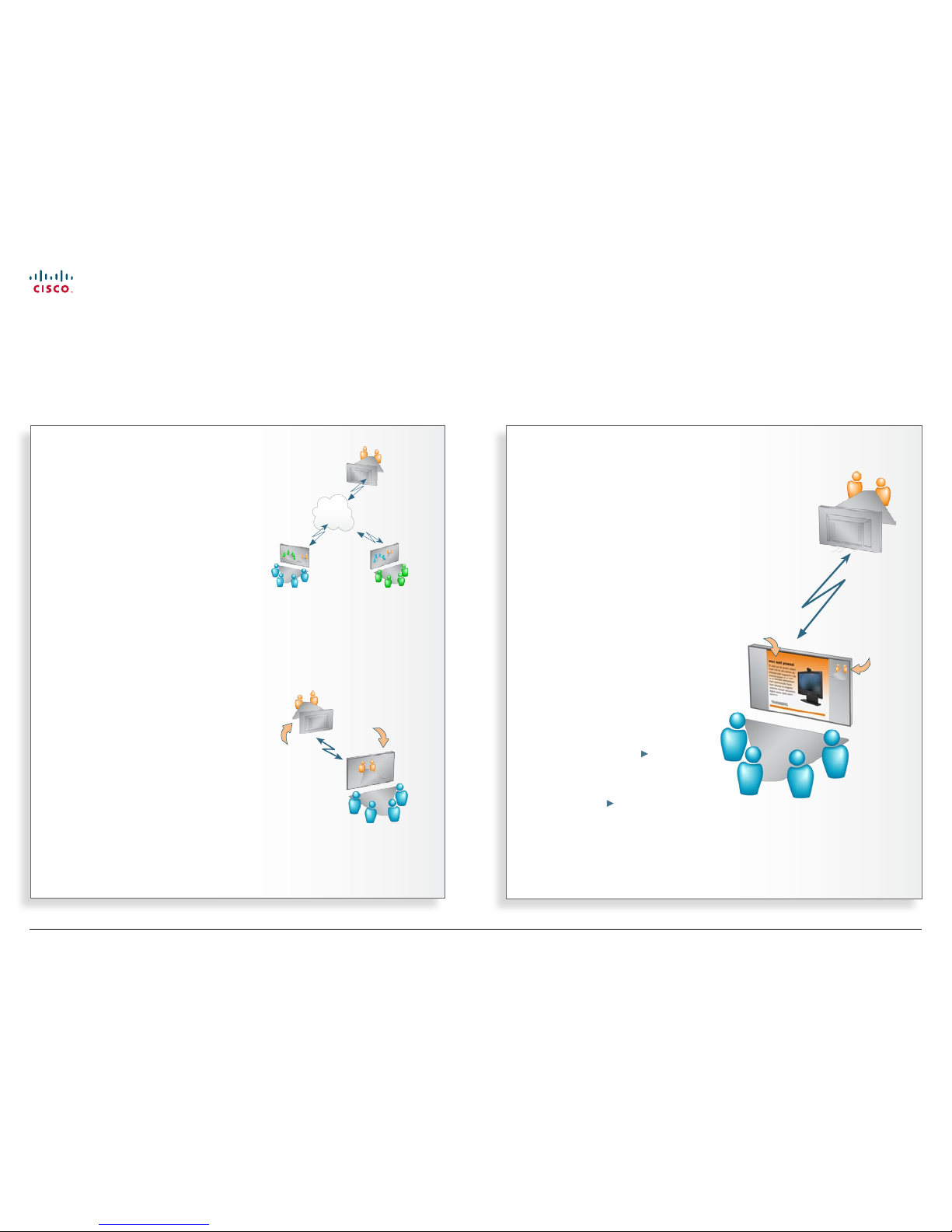
Point-to–point vs. MultiSite
The term point-to–point refers to a
video meeting with no more that two
parties.
Conferences consisting of several
participants are either:
• MultiSite, which refers to a video
conference using your video system’s
built-in conference capabilities, or
• MultiWay, which refers to video confer-
ences using external infrastructure.
MultiSite and Multiway calls
In MultiSite and Multiway calls (i.e.
video conferences with more than
two participants) the term Far End will
loose its meaning since it will not be
unambiguous whom we refer to.
This means that some features normally
available during point-to–point calls—
like far end camera control—won’t be
available during MultiSite calls.
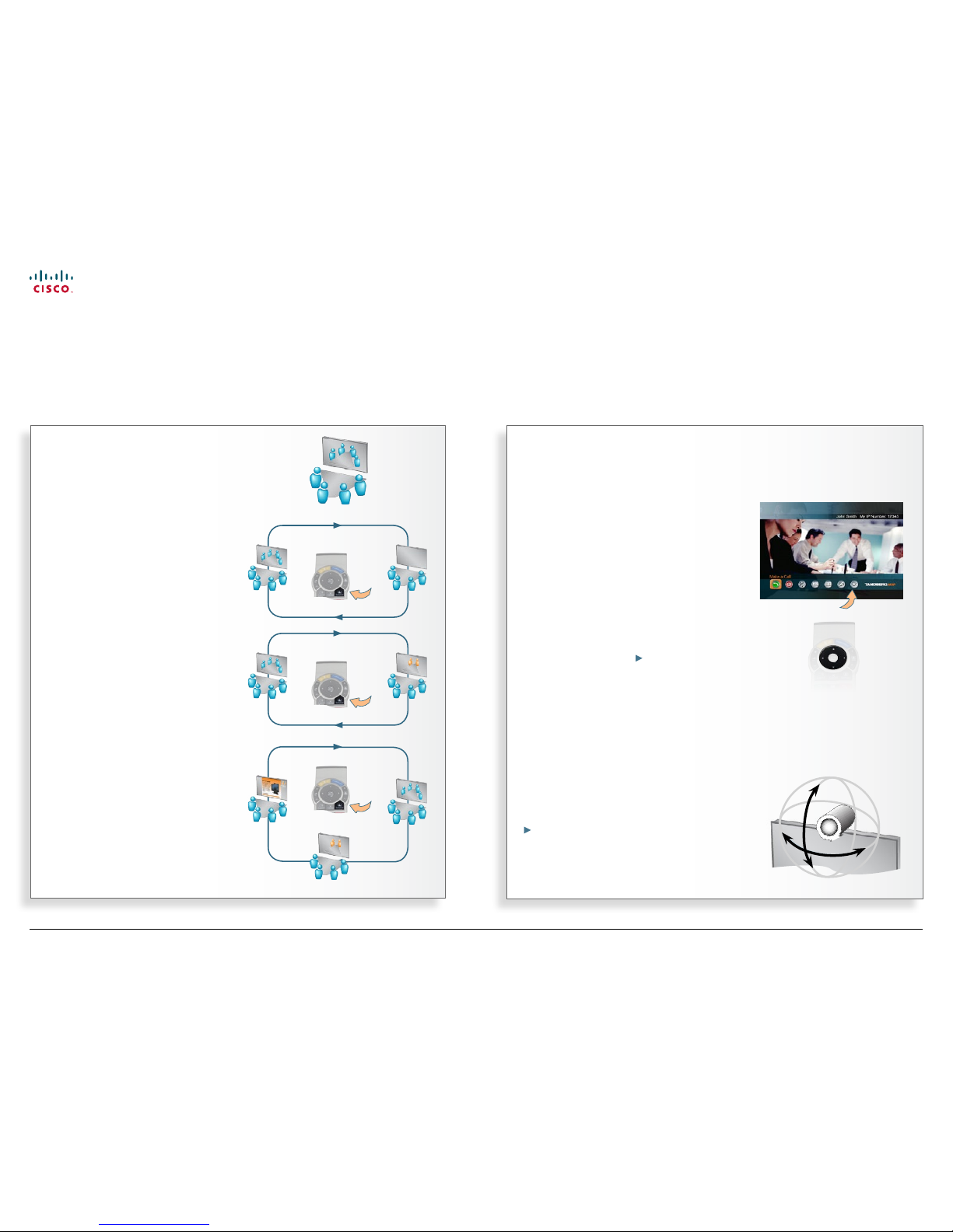
About near end and far end
In a point-to–point video call, your side
is the near end and the other part y
represents the far end.
If you are a
part of the
blue team,
this side of
the video call
will be the
near end...
...the
orange
team will
then be
the far end
for you.
Terminology used
Every environment has its terminology, so also for video conferencing
www.cisco.com
Page 11
11
MXP Series Video Endpoints
User Guide
D1479201 MXP Serie s User Guid e, May 2011.
© 2010-2011 Cisco Sy stems, Inc. A ll right s reserv ed.
Controlling the camera
Most, but not all, of the TANDBERG
meeting room video systems have
cameras that can be controlled from the
remote control.
• The TANDBERG Centric 1000 MXP,
Compass, and Utility have xed cameras
that cannot be moved. Focus can,
however, be adjusted manually.
• The TANDBERG Tactical MXP and
Centric 1700 MXP both have a camera
that can be moved up and down. Focus
is adjusted manually even on these.
When you are in a point-to–point call
you may also be able to control the far
end camera, provided that the far end
system has a remotely controllable
camera— see the chapter
In-call
features.
Controlling cameras at both ends
During a call you may control your
own camera at all times by means of
the Arrow keys as long as no menu is
shown on the screen.
When you are in a point-to–point call
you may also be able to control the far
end camera, provided that the far end
system has a remotely controllable
camera. This is explained in the chapter
Using camera control
What is Selfview?
The term Selfview means the outgoing
image. In a normal video call using the
main camera, this will be the image of
yourself. The Selfview button toggles
the images between Far End, Selfview
and Dual Video Stream (if applicable).
Using Selfview outside calls
Pressing the Selfview key will switch
between the near end video and a
blank screen (or a logo, if uploaded by
your administrator) on the main monitor.
Selfview and Point-to–point
In a point-to–point call, press the
Selfview key once to switch from far
end video to near end video to see
a full screen picture of the outgoing
video. Press Self view again to go back
to normal.
Point-to–point and dual stream
In a point-to–point call with a dual video
stream, the duo video is displayed in
the big picture. Press the Selfview
button to toggle to the near end picture,
then the far end picture, and nally
back to the second video stream.
Selfview and camera control
Playing around with the remote control helps you understand what’s happening
… and use the four Arrow keys
to move the camera to the left,
right, up and down.
Press the Cancel key to remove
the main menu from the screen, if
needed…
Selfview
www.cisco.com
Page 12
12
MXP Series Video Endpoints
User Guide
D1479201 MXP Serie s User Guid e, May 2011.
© 2010-2011 Cisco Sy stems, Inc. A ll right s reserv ed.
Sometimes there are many persons in
the room during a video meeting. To
make the person speaking easier to see
it can be a good idea to zoom in on that
person.
To make the zoom-in somewhat faster
and more elegant, you may employ the
predened camera presets feature.
These presets contain information
about in which direction the camera
should point as well as about the zoom
setting. This is something you typically
will prepare before the video meeting
starts.
The feature applies to endpoints with
cameras that can be controlled from
the remote control only. Consequently,
camera presets are NOT available for:
• TANDBERG Centric 1000 MXP
• TANDBERG Centric 1700 MXP
• TANDBERG Tactical MXP
• TANDBERG Compass/Utility
For the other MXP endpoints a total of
15 presets (0–14) can be dened.
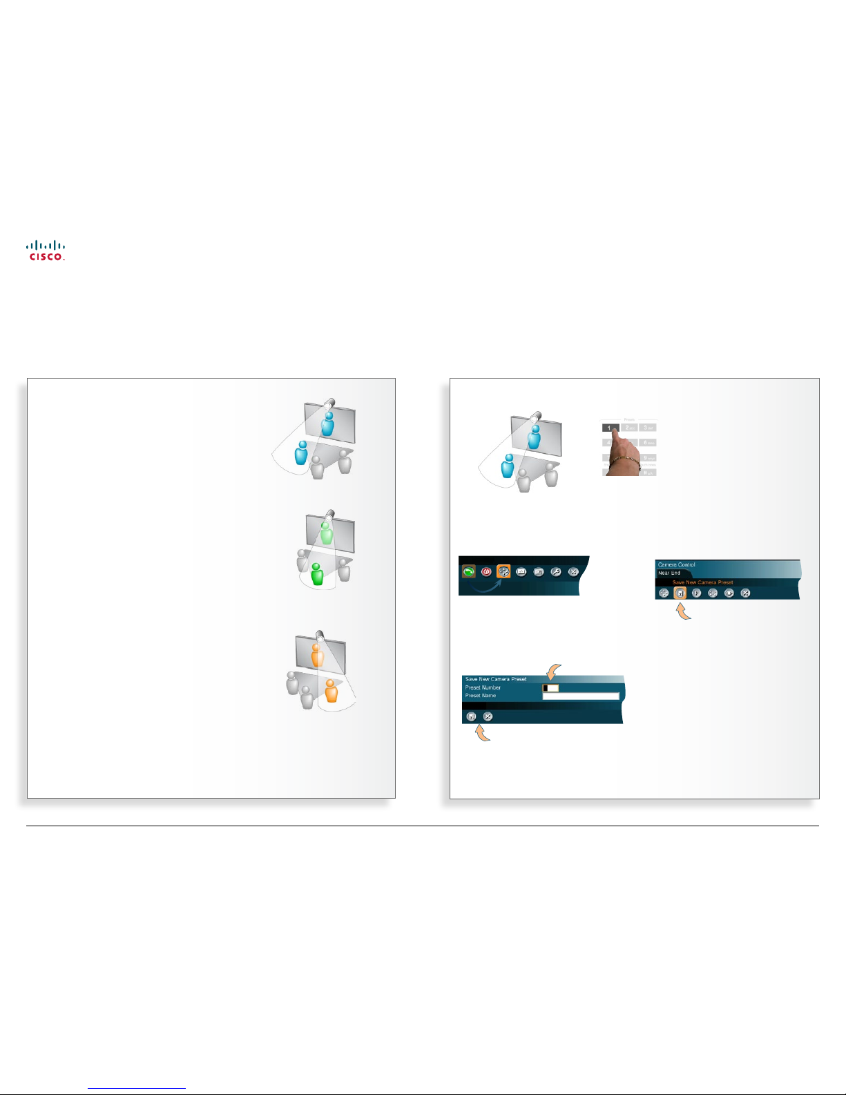
Dening camera presets
Use camera presets to make a quick move and zoom with the camera to see the person speaking
Preset No. 1
Preset No. 2
Preset No. 3
Use the Arrow keys to move the
camera as described on the previous
page.
Then determine which
preset number on the
remote control the position
shall be assigned to
and press and hold the
corresponding key for more
than one second.
The current camera
position is now stored as a
preset.
Storing camera presets as 0–9…
In the main menu, move
cursor to the Camera
Control icon and press the
OK key…
In the submenu
appearing, move the
cursor to the Save New
Camera Preset icon
and press the OK key…
Fill in the Preset Number (0–14) and
optionally a Preset Name to make things
easier to remember and to use.
Select Save and press OK to leave menu putting changes into
eect, or select Cancel to leave undoing any changes.
Storing camera presets as any number 0–14…
www.cisco.com
Page 13
13
MXP Series Video Endpoints
User Guide
D1479201 MXP Serie s User Guid e, May 2011.
© 2010-2011 Cisco Sy stems, Inc. A ll right s reserv ed.
Use as PC screen
If you want to use the video system
screen as your PC screen, we
recommend that your system
administrator sets Use Screen as Local
PC monitor to On. How to do this is
described in the Administrator Guide for
this product.
This implies that you can display
your PC locally while having a video
conference, and you can keep on
working without risking that the
far
end can see what’s on your PC screen.
We also recommend to have the Auto
Layout setting set to On (default) to get
a suitable layout when toggling from
the local PC display mode to standard
video conference mode.
Use the Selfview key to toggle
between local PC display mode and
standard video conference mode. An
indicator tells you that your PC image is
displayed locally.
Picture in Picture (PIP)
When Picture Layout is set to PIP, the
Layout key makes it possible to see
a second image in a smaller view in
one of the corners of the screen. The
second image will be placed on top of
the main image. You are free to choose
in which corner the second image is
to be displayed (press the Layout key
repeatedly).
Picture outside Picture (POP)
When Picture Layout is set to POP, the
Layout key makes it possible to see
up to three images in a composition
optimized for wide screens. The second
image can be displayed either as a
side-by–side the main image (1+1) or
smaller images next to the main image
(1+2 an d 1+3).
Press the Layout key once to get a
side-by-side view (1+1). Press again
to get the layouts 1+2 and 1+3, and
nally go back to full screen view. You
can also go back to full screen directly
by pressing and holding Layout for 1
second.
Example of PIP
(Picture in
Picture).
Example of POP
(Picture outside
Picture).
Using the screen as PC display
Letting the video system and computer share the monitor
Assume that you are
using the video system
monitor as a PC monitor…
… and that you
accept
an incoming call
Local PC displayed
Near end video Far end video
Press the Selfview key
… your screen will
now look like this*.
www.cisco.com
Page 14
14
MXP Series Video Endpoints
User Guide
D1479201 MXP Serie s User Guid e, May 2011.
© 2010-2011 Cisco Sy stems, Inc. A ll right s reserv ed.
Entering standby modeAbout standby
The system will automatically go to
standby mode when it is not in use. In
standby mode, the screen(s) will turn
black. It is, however, still possible to
receive incoming calls.
The standby mode of the system
should be enabled if the system is to be
left idle.
Standby is not activated by
switching o the power to the
monitor(s). Some TANDBERG
systems come with monitors that
cannot be switched o.
If the system is set to be using
the screen as PC display, the
standby mode will be disabled
when the system detects a
video signal from the PC. When
the PC video signal no longer is
detected, the standby mode will
be re-enabled.
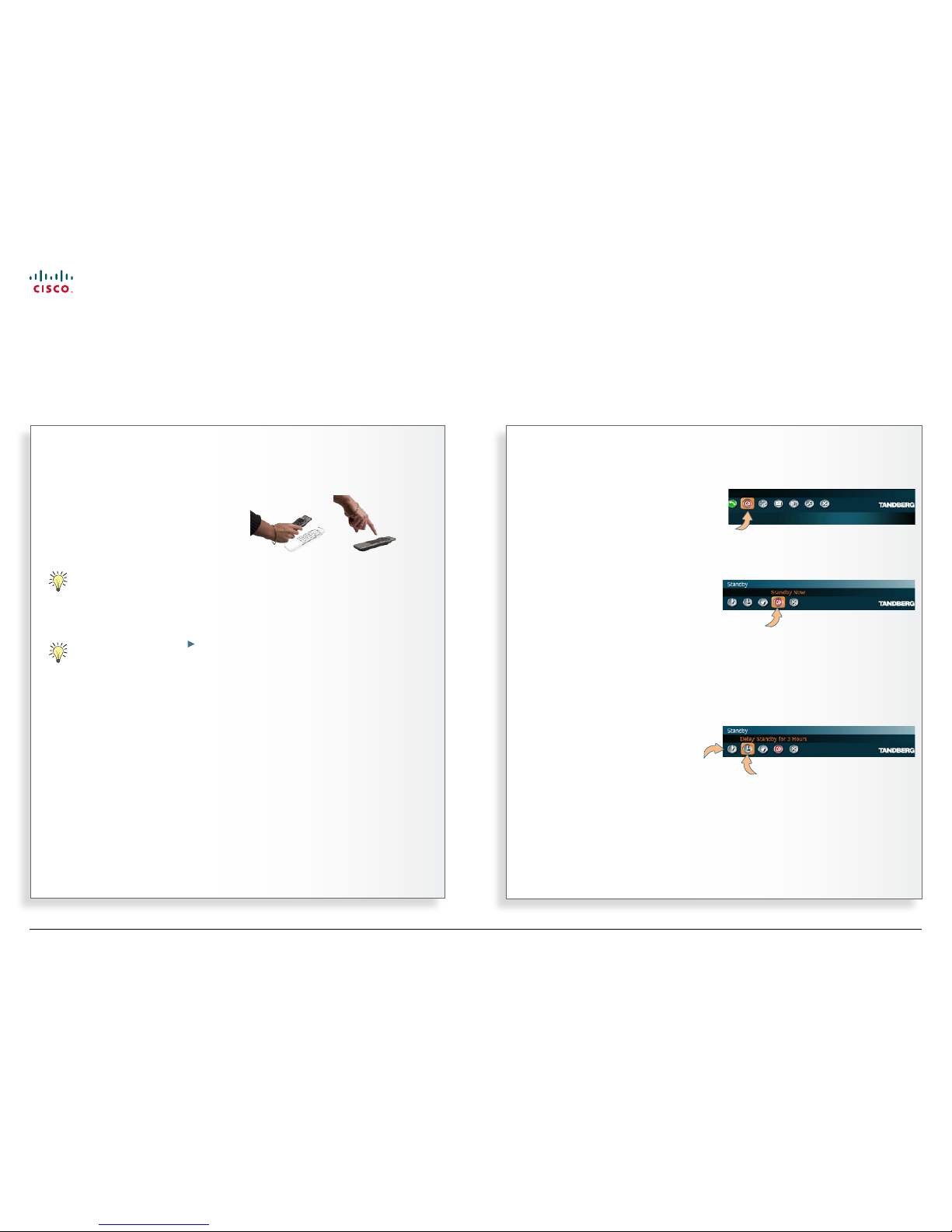
Leaving standby mode
When the system is in standby, pick up
the remote control or press any key to
activate the system again.
Standby
Outside a call, press OK to
produce the main menu, if
needed, and navigate to the
Standby icon.
Press the OK ke y.
To enter standby mode here
and now, navigate to the
Standby Now icon and pres s
the OK key.
However, if you instead want to postpone (delay) the standby for 1 hour or 3
hours, you should select one of the other icons before pressing the OK key.
The below example shows 3 hours delay highlighted (selected).
Select this icon to have
standby postponed
(delayed) by 3 hours.
Select this icon
to have standby
postponed
(delayed) by 1
hour.
www.cisco.com
Page 15
15
MXP Series Video Endpoints
User Guide
D1479201 MXP Serie s User Guid e, May 2011.
© 2010-2011 Cisco Sy stems, Inc. A ll right s reserv ed.
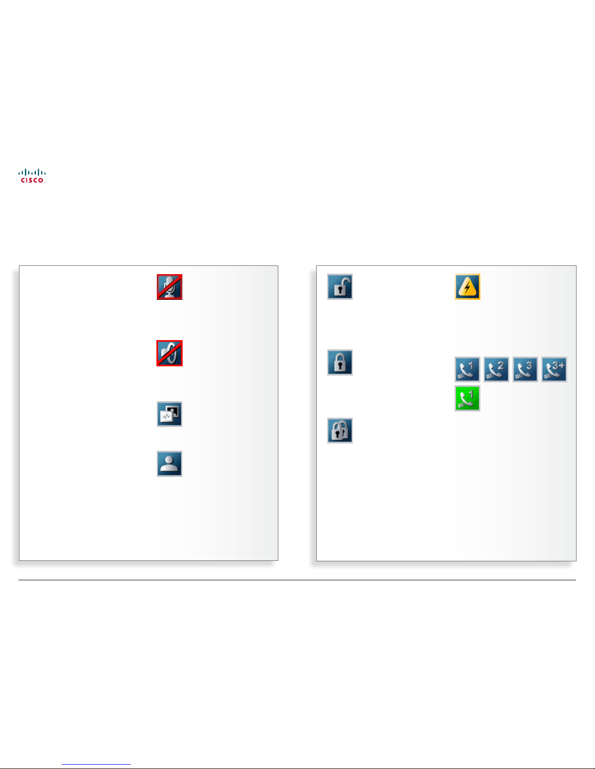
Not Secure Conference. This open
padlock indicator is shown during the
initialization phase for AES or DES
encryption. During this period the call is
not secure.
Secure Conference, AES. This double
padlock indicator is shown when AES
encryption (Secure Conference) is
active.
Secure Conference, AES. This double
padlock indicator is shown when AES
encryption (Secure Conference) is
active.
Bad Network. This indicator appears if
the system detects network anomalies
like packet loss, jitter etc., during a call.
Open the menu by pressing the OK key
and select the warnings icon too see
details.
Telephone. This set of indicators is
shown when there also are telephone
only participants in a multi site
conference.
Indications are given for 1, 2, 3 or more
than 3 participants. Icons turn green
when a telephone participant has the
o o r.
T
o help you immediately realize the
present status of important actions,
states, and events taking place, there
is a number of icons appearing on the
screen, whenever applicable.
Some of these may be turned o, if you
so wish. This is done from the Control
Panel > Icons.
Observe that the Control Panel settings
may have been password protected by
your system administrator.
Microphone O. This indicator is shown
when the microphone is tur ned o.
Press the Mic o key of the remote
control to toggle between On and O.
Volume O. This indicator is shown
when the volume is turned o. Press
Volume + to turn the volume back on.
Dual Video Stream. Dual video stream
activated is indicated by this icon.
On Ai r. When you have the oor in
a conference this is indicated by the On
Air icon.
The icons on the screen
www.cisco.com
Page 16
16
MXP Series Video Endpoints
User Guide
D1479201 MXP Serie s User Guid e, May 2011.
© 2010-2011 Cisco Sy stems, Inc. A ll right s reserv ed.
Chapter 2
Making calls
In this chapter…
Access codes
To make a call dialing the number
Altering call settings before calling
Making calls using the phone book
Ending an ongoing call
Answering an incoming call
Using the Do Not Disturb feature
Streaming
Calling two others at the same time
Consultative transferring of calls
Unattended transferring of calls
About video conferences
www.cisco.com
Page 17

17
MXP Series Video Endpoints
User Guide
D1479201 MXP Serie s User Guid e, May 2011.
© 2010-2011 Cisco Sy stems, Inc. A ll right s reserv ed.
When the system asks for codes
When the system asks for access
codes, a dialog box will appear,
prompting you to enter a valid code.
Use the remote control to enter the
code. Note that the system expects text
entries, similar to when using a mobile
phone to send text messages (sms)—
see for details.
Y
our TANDBERG system may, or may
not, have been set up to require
access codes to be typed in before a
call can be made.
Access codes are used for t wo things:
• Call restrictions. These may be
applied by installing a le of valid
access codes that must be entered
to permit calls to be made. This
installation is typically made from
TMS (TANDBERG Management
Suite—available separately).
• Billing opportunities. Assume that
an access code is needed whenever
you make a call. Your company may
have dierent access codes for the
dierent clients of your company.
Then, the access code used may
be picked up by TMS to generate
statistics on who is calling whom,
when, and for how long time.
This information may later form
the basis for billing clients or
departments. Obser ve that in this
case there will be no strict need for
installing an access code le on your
system—TMS will still have access to
the codes you have assigned to the
calls. In this case any code entered
will be considered valid.
Of course, the two applications may be
combined to form a billing system with
call restrictions. This will then become a
system that acts as forced billing.
Access codes should be activated by
your system administrator.
How to do this is described in the
Administrator Guide which can be
downloaded from http://www.tandberg.
com/docs.
Access codes
Text entries are expected.
www.cisco.com
Page 18

18
MXP Series Video Endpoints
User Guide
D1479201 MXP Serie s User Guid e, May 2011.
© 2010-2011 Cisco Sy stems, Inc. A ll right s reserv ed.
Video vs. telephone calls
Before you make a video or telephone
call, make sure the system call t ype is
set up accordingly.
What type of calls the system has
been set up to right now is indicated
by a little icon to the left of the Call
Settings el d:
This icon s hows that v ideo cal ls
are expecte d to be made.
This icon s hows that te lephone
calls are ex pected to be m ade.
In order to change the setting, you
must navigate to that icon:
Press the OK key on the remote
control to display the submenu:
Assuming that you would like to make
a telephone call in this example, you
must navigate down to Telephone call
to change it from Video Call. Press the
OK key to put the changes into eect.
Repeat to select the other set ting.
To make a call dialing the number
Making a call
… or select the
Call icon of
the main menu
before you
press OK key.
The Call menu is then displayed…
Enter the “number” here (it
may consist of digits as well
as letters) using the remote
control.
Start by
pressing
the green
Call key on
the remote
control…
Once you have nished entering the number, start calling by: …
… pressing
the green
Call key on
the remote
control…
5598760 2
… or by navigating down to the green Call
icon and pressing the OK ke y.
Instead of navigating down to the Call icon, you may also just press the OK
key twice to star t calling.
www.cisco.com
Page 19

19
MXP Series Video Endpoints
User Guide
D1479201 MXP Serie s User Guid e, May 2011.
© 2010-2011 Cisco Sy stems, Inc. A ll right s reserv ed.
Menu details
About call settings
Normally, you would leave it up to the
system to decide the optimal settings
for a call, but sometimes a lit tle
tweaking may be benecial. For this
purpose there is a set of call settings
that you may utilize to force a call to be
the way you want.
These settings are:
• Choosing between ISDN, H.323 and
SIP as network and protocol to be
used.
• Bandwidth restrictions, if needed.
Once you have dened these call
settings you may set these to serve as
default call settings from now.
Altering call settings before calling
To gain access to the Net(work) settings, navigate to this and
press the OK key to expand it. You will then have the following
options:
Auto. Leaves it up to the system to decide what to use
(recommended).
ISDN. For ISDN capable systems only.
H.323. For H.323-based communication.
SIP. For SIP-based communication.
System. Dened by your administrator. Allows prexes and
suxes for use with additional infrastructure equipment to be
added automatically.
To gain access to the Bandwidth settings, navigate to this
and press the OK key to expand it. You will then have the
following options:
Auto. Leaves it up to the system to decide what to use
(recommended).
Dened by you. Choose between 64, 128, 192, 256, 320,
384,
512 or 768 [kbps]
Max. The highest rate possible.
Restrict (56K). Used in the US to restrict the bandwidth whenever needed while
communicating using ISDN.
Set as Default. Once you have made a set of settings, you may let these settings become
the default set tings from now on.
Navigate to OK and press the OK key to leave the menu putting changes into eect, or to
Cancel and press the OK key to leave menu undoing any changes made.
Navigate to the Call Settings
eld and pres s OK on the remote
control...
www.cisco.com
Page 20

20
MXP Series Video Endpoints
User Guide
D1479201 MXP Serie s User Guid e, May 2011.
© 2010-2011 Cisco Sy stems, Inc. A ll right s reserv ed.
The phone book:
M
aking use of the phone book is
time saving and prevents you from
inadvertently calling the wrong number.
The entries, often referred to as
contacts, are sorted alphabetically. The
contact names are displayed in the list
and the telephone or video numbers of
the selected contact will be displayed at
the bottom line.
When selecting Phone Book, the phone
book opens showing the folders Placed
Calls, Missed Calls, Received Calls
and My Contacts. There may also be
a corporate phone book called Global
Contacts. If so, such contacts will be
listed below these folders.
Making calls using the phone book
… or click on Call
icon of the main
menu…
… start by
pressing
the Phone
Book key on
the remote
control…
… and then navigate to
the Phone Book icon
before pressing
the OK key.
Use the Arrow keys of the remote control to
navigate in the lists.
Entries with an arrow
appended are expandable,
press the OK key to
display the expanded list.
You may key in letters
using the remote control
to search in the list. The
more letters, the more
narrow the result list
becomes.
Once you have located whom to call, navigate down
to that entry by means of the Arrow keys …
… and press the
green Call key
on the remote
control to start
calling the
selected entry
immediately.
www.cisco.com
Page 21

21
MXP Series Video Endpoints
User Guide
D1479201 MXP Serie s User Guid e, May 2011.
© 2010-2011 Cisco Sy stems, Inc. A ll right s reserv ed.
Y
ou end an ongoing call in the same
way as you do when using a mobile
phone— by pressing the red End Call
key on the remote control. This will
produce the Call menu.
Note! Switching o the monitor(s) using
the power on/o switch on the monitor
will not end an ongoing call. Some
systems even come with monitors that
cannot be switched o!
Ending conference calls
Ending a MultiSite call can only be done
by the host. The host is the party that
initiated the video conference.
The other par ties can disconnect
themselves from the conference at any
time, but they have no inuence on the
rest of the conference.
To end one or a few of the calls in a
MultiSite video conference, navigate to
the name of the call to be terminated
and terminate that specic connection
as if it were a simple point-to-point call.
Ending an ongoing call
Ending point-to–point calls
Press the End C all key or the OK key on
the remote control…
This will cause the End Call dialog box
to be displayed…
Then press the End Call key or the OK
key on the remote control again…
Ending MultiSite calls
Press the End C all key or the OK key on
the remote control…
This will cause the End Call dialog box
to be displayed…
Then press the End Call key or the OK
key on the remote control again…
www.cisco.com
Page 22

22
MXP Series Video Endpoints
User Guide
D1479201 MXP Serie s User Guid e, May 2011.
© 2010-2011 Cisco Sy stems, Inc. A ll right s reserv ed.
When someone calls you…
A
nswering an incoming call can be
automated if you so wish, or you
can have the system set up so that it
requires that you physically accept the
incoming call by pressing the green
Call key on the remote control or the
corresponding icon on the screen.
About incoming calls and privacy
You may want to set up your system
so that the microphone is switched o
whenever you receive an incoming call.
The yellow Microphone O key on
the remote control can be operated
to prevent callers from hearing you
without your control. Press again to
reactivate the microphone.
If the system is set up to automatically
accept incoming calls with the
microphone set to On, this is called
setting Autoanswer to On.
Your system may, however, be set
up so that it automatically accepts an
incoming call, but with the microphone
switched o. This is called setting
Autoanswer to On + Mic O and will
require that you switch the microphone
back on manually each time someone
calls you.
To further increase the sense of
privacy, you may also have your system
set up so that you always must answer
all incoming calls manually.
These settings are par ts of the
Control Panel Settings available.
Your administrator may, or may not,
have password protection activated
to prevent unauthorized alterations of
these and other settings. If in doubt,
consult your administrator.
A message will be sent to the far end
whenever you have disabled your
microphone and/or your camera.
An alternative to this could be the
use of the do not di sturb feature (next
page).
Want a dierent ring tone?
You are not stuck with the audio signal
alerting you that an incoming call is on
its way. This may be changed in the
Audio Settings in the Control Panel
section. Note that these set tings may
have been password protected by your
administrator.
Answering an incoming call
… this menu is displayed on the screen of your video system:
Navigate to
here and press
the OK key to
accept the call.
Navigate to here
and press the OK
key to reject the
call.
Navigate to here and
press the OK key
to activate Do Not
Disturb.
This will not apply
if Do Not Disturb
already has been
activated, nor
will it apply if
Autoanswer has
been set to On or
to On + Mic O.
See the next page
for details.
If the microphone has been
deactivated, press the yellow Mic o
key to reactivate.
Alternatively, you may use the keys of the remote control directly:
Press the green Call
key to accept the
call.
Press the red En d Call
key to reject the call.
www.cisco.com
Page 23

23
MXP Series Video Endpoints
User Guide
D1479201 MXP Serie s User Guid e, May 2011.
© 2010-2011 Cisco Sy stems, Inc. A ll right s reserv ed.
Using Do Not Disturb
Use the feature as follows:
1. Outside a call, press the red End Call
key. In the menu then appearing,
navigate to the Do Not Disturb icon:
2. Press the OK key to activate this
feature. The screen will turn black
and the text Press any key to clear
Do Not Disturb will be shown.
3. To reset the function, do just that
(press any key).
There is a do not disturb function
available on your system. When set to
On, all incoming calls are blocked from
your system.
Let us assume that the do not distu rb
function has not been activated.
Choosing Do Not Disturb (as shown to
the left) when receiving an incoming
call will then do two things: It rejects
the incoming call (in the same way as
choosing Reject), and sets the do not
disturb functionalit y to On.
If you activate Do Not Disturb whilst in
a call, this will block incoming calls for
as long as your call is going on.
Whenever the d o not disturb function
has been activated, the far end will be
informed that the called is busy.
Using the Do Not Disturb feature
Blocking incoming calls
www.cisco.com
Page 24

24
MXP Series Video Endpoints
User Guide
D1479201 MXP Serie s User Guid e, May 2011.
© 2010-2011 Cisco Sy stems, Inc. A ll right s reserv ed.
Setting up for streaming…
S
treaming lets you broadcast your
meeting to par ticipants on the
web. The web par ticipants can view
the meeting, listen to the meeting,
see snapshots, but not par ticipate
the mselves. Snapshots of current
stream, selfview, far end and dual video
streams are accessible via http.
The streaming source setting is not
available when streaming only is
supported outside a call.
Streaming settings
Address. This is dened as the
IP-address of a streaming client,
streaming server or a multicast
address. Giving an address in the
range 224.0.0.1–239.255.255.255 wil l
broadcast the stream to any host that
has joined the specied multicast group.
Specifying normal broadcast address
255.255.255.255 will broadca st to any
members on the LAN.
Address Port. If several codec’s are
streaming to the same IP-address,
dierent por ts have to be used in order
for the client to know which stream to
receive. If the r st codec streams on
port 2240 and the second codec on port
2250, the client has to specify which
port to listen to. Video is transmitted on
the specied port; audio is transmitted
on the port number 4 greater than the
specied video port, in this case 224444
and 2254.
TTL/Router Hops. This is used for
streaming data to limit how many
routers the data should pass before it is
rejected. If TTL is set to 2, data will not
traverse more than 2 router hops.
Streaming Source. The source used for
streaming.
Auto: Enables streaming of both local
and far end video. Selection of which
site to be streamed is done using
voice switching (the site that speaks is
streamed).
Local: Only the local video will be
streamed.
Remote: Only the far end video will be
streamed.
Local and far end audio is always
streamed.
Streaming
Part 1: Setting up to broadcast your meeting to participants on the web
In the Make a Call menu, select
the streaming icon and press
the OK key on the remote
control…
Select Streamer Settings
and press the OK key
again…
Address
Address Por t
TTL/Router Hops
Streaming Source
Allow remote Start
Announcements
Video rate
Password
The Streamer Settings will now be displayed…
www.cisco.com
Page 25

25
MXP Series Video Endpoints
User Guide
D1479201 MXP Serie s User Guid e, May 2011.
© 2010-2011 Cisco Sy stems, Inc. A ll right s reserv ed.
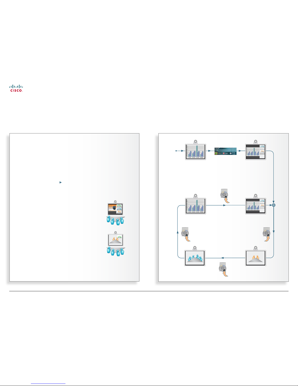
Streaming a video meeting…
S
treaming lets you broadcast your
meeting to par ticipants on the
web. The web par ticipants can view
the meeting, listen to the meeting,
see snapshots, but not par ticipate
the mselves. Snapshots of current
stream, selfview, far end and dual video
streams are accessible via http.
Viewing the streamed content
After streaming is star ted, an easy way
to view the streamed audio/video on
your PC, is to star t your web browser
and enter the IP-address of the
streaming system.
Once the web page of the system
is shown, click on Streaming.
Alternatively, enter http://<codec/ipaddress>/showstream.ssi.
If in doubt, consult your system
administrator.
Streaming
Part 2: Broadcasting your meeting to participants on the web
Whilst in a call, press the green Call key on the
remote control and navigate to Streaming…
Press the OK key to produce the Streaming
submenu. Navigate to Start Streaming and press
the OK key…
During streaming the Star t Streaming icon will change to Stop
Streaming. Select this icon and press the OK key to stop streaming.
Ending your call will also halt the streaming.
www.cisco.com
Page 26

26
MXP Series Video Endpoints
User Guide
D1479201 MXP Serie s User Guid e, May 2011.
© 2010-2011 Cisco Sy stems, Inc. A ll right s reserv ed.
Calling two others simultaneously …
T
he MultiSite capabilit y is an optional
feature in many TANDBERG
systems. This feature gives you the
possibility of arranging video meetings
by calling several others and have you
all connected together simultaneously.
For more on this, see About video
conferences.
Video systems not equipped with
MultiSite may still call another party
when already in a call.
Thus you may even here have two
calls running at the same time. Note
that the two parties will not be able to
communicate with each other, only with
you and only one at a time. The feature
requires H.323 or SIP to work.
If you are not sure whether your system
has this feature, contact your system
administrator.
When you make an additional call, the
party called rst will be temporarily
suspended. The message “Please wait”
will appear on the screen of the party
suspended.
You may switch between the two
parties you have called by navigating to
the lowermost line in the main menu as
shown on this page.
This feature is not available on systems
with MultiSite installed.
Both calls made must be SIP or H.323
in order to make this feature work. This
feature is available on non-MultiSite
systems only. If in doubt, ask your
system administrator.
Calling two others at the same time
Non-MultiSite systems only!
If you select
Add another
Call during a call
(press the OK key
on the remote
control during the
call) and then
press the OK
key again…
… the call currently active will be
temporarily be set On Hold, which
can be seen from this line.
Call the second part y
manually or by means of
the phone book in the usual
manner.
To switch
between the
two parties,
navigate
down to
this line and
press the
OK key on
the remote
control.
To terminate just
one of the calls,
use the Arrow keys
to navigate to that
number and press the
red End Call key on
the remote control. If
you want to terminate
both calls at the same
time, press the red
End Call key again.
To end any or both of the calls,
press the End Call button on
the remote control. The menu
will then look something like
this…
www.cisco.com
Page 27

27
MXP Series Video Endpoints
User Guide
D1479201 MXP Serie s User Guid e, May 2011.
© 2010-2011 Cisco Sy stems, Inc. A ll right s reserv ed.
Transferring calls …
D
uring a call you may transfer the
other party to a third party and
disconnect yourself from the call.
Call transfer comes in two avors:
Consultative transfer. (This page) takes
place when you have called two parties
at the same time (as discussed on the
previous page) and decide that you
want to connect the two, while at the
same time disconnecting yourself.
Unattended transfer. (Next page) This
takes place when you transfer a call to
someone else without already being
in a video call with that par ty. Observe
that unattended call transfer only works
on non-MultiSite systems. Furthermore
the feature applies to SIP calls only!
If you are in doubt whether your system
is a non-MultiSite system or you have
questions about SIP calls, contact your
system administrator.
Consultative transferring of calls
Non-MultiSite systems only!
Assume that you are already connected
to two others at the same time—similar to
what is outlined on the previous page.
One or both of these may have called you.
There is no requirement that any of the
calls must have been initiated by you.
To connect the two parties together and
thereby disconnecting yourself, press the
OK key on the remote control to display
the Call menu (which now will have a
slightly dierent look), navigate down to the
Tra n sfe r icon, and press the OK key again.
www.cisco.com
Page 28

28
MXP Series Video Endpoints
User Guide
D1479201 MXP Serie s User Guid e, May 2011.
© 2010-2011 Cisco Sy stems, Inc. A ll right s reserv ed.
Transferring calls …
D
uring a call you may transfer the
other party to a third party and
disconnect yourself from the call.
Call transfer comes in two avors:
Consultative transfer. (Previous page)
takes place when you have called two
parties at the same time (as discussed
on the previous page) and decide that
you want to connect the two, while at
the same time disconnecting yourself.
Unattended transfer. (This page) This
takes place when you transfer a call to
someone else without already being
in a video call with that par ty. Observe
that unattended call transfer only works
on non-MultiSite systems. Furthermore
the feature applies to SIP calls only!
If you are in doubt whether your system
is a non-MultiSite system or you have
questions about SIP calls, contact your
system administrator.
Unattended transferring of calls
Non-MultiSite systems only!
The call will now be transferred and you will be disconnected.
Assume that you are already in a call with
someone. If you now call another using the
method described two pages back
Calling two other s at the same time
Both calls must, however, be of SIP type.
To connect the two parties together,
navigate down to the Tra n sfe r ca l l icon and
click the OK key on the remote control.
www.cisco.com
Page 29

29
MXP Series Video Endpoints
User Guide
D1479201 MXP Serie s User Guid e, May 2011.
© 2010-2011 Cisco Sy stems, Inc. A ll right s reserv ed.
Conference calls …
V
ideo conferencing systems quipped
with the optional built-in MultiSite
can handle several video calls and
telephone-only calls simultaneously.
How many depends on the type of
TANDBERG video system you are using.
You may set up a video meeting with
many participants in advance and/
or you may add par ticipants during
a conference. This is called to add
another call.
Observe that the ability to add calls is
an optional feature, which your system
may, or may not, be equipped with.
Systems without this option will have no
Add Another Call icon in the menus.
Using phone book group entries
For your convenience, it is possible to
add group entries to the phone book.
More on this can be found in
Phone
book usage.
IP and ISDN communication
Some TANDBERG systems use
IP (Internet Protocol) for video
communication, while others use ISDN
as well as IP.
Observe that in order to be able to
communicate with 3G mobile phones
and to enable communication between
ISDN- and IP-based systems, access
to additional functionality hardware may
be required.
Consult your system administrator or
your TANDBERG representative for
details.
How many participants?
This depends on the conguration of
your TANDBERG system. The larger
systems have an optional built-in MCU
(Multi Conference Unit) opening up
for 4–6 simultaneous participants plus
extras on voice-only (telephone), while
the smaller systems do not have this
feature at all.
All systems can, however, be
connected to a net work containing
external MCUs. These MCUs are
capable of running several video
conferences with many participants
each, simultaneously. read more about
this on the next page
To learn more about the actual
conguration available in your system,
contact your system administrator.
About video conferences
Part 1: The basics
If you are the one who initiated the
video conference, you are considered to
be the host by the system.
In MultiSite calls (i.e. video conferences with
more than two participants) the term Far End will
loose its meaning since it will not be unambiguous
whom we refer to.
This means that some features normally available
during point-to–point calls—like far end camera
control—won’t be available during MultiSite calls.
www.cisco.com
Page 30

30
MXP Series Video Endpoints
User Guide
D1479201 MXP Serie s User Guid e, May 2011.
© 2010-2011 Cisco Sy stems, Inc. A ll right s reserv ed.
Adding calls to a conference…
The MultiSite feature
Conference systems with the optional
built-in MultiSite can handle up to 4–6
video calls and up to 3 telephone calls
simultaneously, depending on the
system.
You may set up a video meeting with
many participants in advance and/
or you may add par ticipants during
a conference. This is called to add
another call.
Observe that the ability to add another
call is an optional feature, which your
system may, or may not, be equipped
with.
Systems without this option will not
have the Add Another Call icon in the
menus.
The Multiway feature
However, your system may be equipped
with the MultiWay feature. This feature
allows you to set up conferences with
many participants from your video
system.
MultiWay enables systems with no
conference option installed to run
complex video conferences with many
participants.
The MultiWay feature requires the
presence of an external MCU (Multi
Conference Unit) and the TANDBERG
VCS (Video Communication Server).
The MCU will r un the conference for
you, if your system does not support
conferencing.
Consult your system administrator to
clarify whether this feature exists in
your system, if needed.
Using phone book group entries
If you dislike the idea of having to
look up each and every par ty to call
every time you are about initiate a
conference, you may like to know that
you may add group entries to the phone
book.
This is a handy feature whenever you
want to set up meetings with the same
group frequently.
More on this can be found in
Phone
book usage.
About video conferences
Part 2: Adding calls to a conference
Assuming that you already are in a call, pres s the OK key to produce the main menu,
which now looks slightly dierent:
Select this icon
and press the OK
key to start adding
participants…
The one you are already in call with.
Enter new “number”
here.
Select this icon and press
the OK key to open the
phone book as usual.
Once you have entered the second party to call, select the
green Call icon and press the OK key, just press the green Call
key on the remote control.
The Add Another Call
icon.
Repeat this process for as long as necessary (until the
upper limit is reached for your system, of course).
You may also use the Add Another Call icon to specif y
everyone to be called before you actually call them.
www.cisco.com
Page 31

31
MXP Series Video Endpoints
User Guide
D1479201 MXP Serie s User Guid e, May 2011.
© 2010-2011 Cisco Sy stems, Inc. A ll right s reserv ed.
Chapter 3
Phone book usage
In this chapter…
Basic phone book features
Searching the phone book
Adding new contacts
Editing existing entries
Creating MultiSite entries
Editing and deleting MultiSite entries
www.cisco.com
Page 32

32
MXP Series Video Endpoints
User Guide
D1479201 MXP Serie s User Guid e, May 2011.
© 2010-2011 Cisco Sy stems, Inc. A ll right s reserv ed.
Entering the phone book…
Calling an entry
Once an entr y is located, just press the
OK key to have the entry inserted in the
Call menu and proceed by pressing the
green Call key or via the green icon in
the menu as usual.
Navigating in the phone book
• Basic navigation in the phone book
is done in the usual way by means of
the Arrow keys of the remote control
as well as the OK and Cancel keys.
• When positioned at a line with a
small arrowhead appended, press
the OK key to go one level down.
Repeat, if needed, if there are more
levels.
• Whenever you are at a lower level,
the uppermost line contains the
option of going Back—just navigate
to this eld and press the OK ke y.
Y
our TANDBERG video system
contains a phone book functionality,
which is very similar to what you nd in
a mobile phone.
It contains lists of calls placed,
calls missed and calls received.
Furthermore, it has a section in which
you can add your own list of contacts,
and most corporate solutions will also
include a corporate phone list.
This latter list is normally installed and
maintained from remote by your system
administrator through a management
system like the TANDBERG
Management Suite (TMS), which is
available separately.
You cannot edit the corporate list
yourself, but you may import any
number of entries to My Contacts.
Once impor ted they may, however, be
edited ad libitum.
Changes in the corporate list made by
your system administrator, will not aect
the My Contacts list, so you may have
to check and compare your own list to
the corporate list from time to time.
Entries in My Contacts can be
combined in groups, so that you can
call an entire group simultaneously
when you are about to be hosting a
video conference.
Basic phone book features
Getting started with the phone book
Press the Phone
Book key on the
remote control…
… or select the Phone Book
icon in the Make a Call menu
and then pres s the OK key:
This will cause the phone book to
open…
The arrowhead appended shows that there is more than meets the
eye here. Press the OK key to enter the sublist.
The lists of calls you have placed,
missed, and received.
The corporate list.
Your personal
list of contacts.
www.cisco.com
Page 33

33
MXP Series Video Endpoints
User Guide
D1479201 MXP Serie s User Guid e, May 2011.
© 2010-2011 Cisco Sy stems, Inc. A ll right s reserv ed.
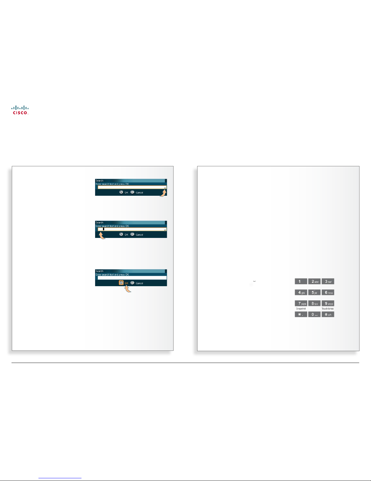
Searching the phone book…
Entering text in the search eld
Example: Entering Alic e 123 in the Search input eld in the phone
book:
1. Pres sing 1 × 2-key gives A.
2. Pressing 1 × #-key switches bet ween ABC and abc.
3. Pressing 3 × 5-key gives l.
4. Pressing 3 × 4-key gives i.
5. Pressing 3 × 2-key gives c.
6. Pressing 2 × 3-key gives e.
7. Pres sing 1 × 0-key gives space.
8. Pressing 3 × 1-key gives 1.
9. Pressing 4 × 2-key gives 2.
10. Pressing 4 × 3-key gives 3.
Y
ou may use the Qu ick Search
by Lett ers to nd and entry.
Whenever you are inside the phone
book navigating in the list of entries,
the numerical keypad automatically
switches from 123 mode to ABC mode.
To locate a specic entr y, just type in
the rst let ter as with a mobile phone.
Observe that:
• You need to be within a folder in the
phone book
• The quick search is made within that
folder only.
If you are not sure which folder the
contact resides in, you may instead use
the search function outlined in the Fig.
This search function searches within all
the folders of your phone book.
When a search in the phone book is
made by means of the Search function,
contacts matching the search text are
displayed only. Navigate to the Back
line and press the OK key to return to
the alphabetical list.
Searching the phone book
Using the Quick Search by Letters feature
Assuming that you have already opened
the phone book use the Arrow keys to
navigate to the Search icon and press
the OK key…
Enter the search string (the entr y you are
looking for) and press the OK key or move
down to the OK icon and press the OK ke y.
(To leave the menu cancelling your search,
press Cancel or move down to the Cancel
icon and press OK).
As an example, let us consider a search for
the entry Alice…
In our example the result of this search
returned three entries…
… to call any of them, navigate down to the
one to call and press the OK key to copy the
entry to the Make a Call menu.
www.cisco.com
Page 34

34
MXP Series Video Endpoints
User Guide
D1479201 MXP Serie s User Guid e, May 2011.
© 2010-2011 Cisco Sy stems, Inc. A ll right s reserv ed.
Adding a new contact from scratch…
Adding a new contact from the
call log
If you want to add an entry directly from
any of the call logs, do as follows:
1. Go to the log, in which the entry to
be added resides.
2. Navigate to that par ticular entry.
3. From that entry navigate left and
down to the New icon.
4. Press the OK key and the entry will
now be stored in My Contacts.
Copying from the corporate
phone book
This is done in exactly the same way as
when adding a new contact from any of
the call logs:
• Go to where the entry to be copied
resides and do as described above.
N
ew contacts can be added
manually, from the call log or by
copying from the corporate phone
book (if existing). New contacts can
be added to My Contacts only. Other
entries are entered by you system
administrator.
If you do video conferencing with many
participants on a regular basis, you may
want to create groups of contacts to be
able to call them all in one go. Groups
can only be made from entries already
in the My Contacts list.
Adding new contacts
Contacts can be added manually or copied from phone book and call logs
Once you have
selected the
entry to be
added to My
Contacts, move
to this icon and
press the OK
key.
To be able to add new contacts
you must have opened the phone
book and be located within My
Contacts…
…then navigate to the
New icon…
Press the OK key and enter name and “number” of the new contact…
Specify Call type,
Net, Bandwidth
and Restrict (ISD N
systems only), if
applicable. If in
doubt, consult
your system
administrator.
www.cisco.com
Page 35

35
MXP Series Video Endpoints
User Guide
D1479201 MXP Serie s User Guid e, May 2011.
© 2010-2011 Cisco Sy stems, Inc. A ll right s reserv ed.
Editing an entry…
Discarding an entry
Entries in My Contacts and in any of the
call logs may be discarded at any time.
Do as follows:
1. Go to where the entry to be
discarded resides, this can only be
one of the call logs or My Contacts.
2. Navigate to that par ticular entry.
3. From that entry navigate left and
down to the Delete icon:
Once you have
selected the
entry to be
discarded,
move to this
icon and press
the OK key.
4. Press the OK key and the following
dialog box will appear:
5. Press the OK key to leave menu
undoing any changes.
Y
ou may edit and delete entries in My
Contacts any time. Since updates
in the corporate phone book(s) made
by your system administrator will not
aect My Contacts, you may have to
use this feature from time to time when
corporate phone book changes are
made.
Observe that you cannot edit any other
parts of your phone book except the
contents of your call logs, all of which
entries can be copied to My Contacts
(as described on the previous page) or
they can be discarded.
Editing existing entries
Contact information can be updated or removed from the phone book
Editing can only take place among
entries in My Contacts.
Start by selecting the entry to
edit…
…then navigate to the
left and down to the
Edit icon and press the
OK key…
Edit the contact…
Navigate down to the OK and press the OK key to
leave the menu putting changes into eect.
Or, navigate to Cancel and press the OK key to leave
menu undoing any changes.
www.cisco.com
Page 36

36
MXP Series Video Endpoints
User Guide
D1479201 MXP Serie s User Guid e, May 2011.
© 2010-2011 Cisco Sy stems, Inc. A ll right s reserv ed.
About Multisite and Multisite entries
Assume that you frequently use your video system to set
up MultiSite video meetings involving the same persons
every time.
Wouldn’t it be nice to be able to set up the video meeting
with just a few clicks?
Enter MultiSite Contacts. You may assign contacts already
in your phone book to a MultiSite group. This group will
in turn form a MultiSite Contact. When set ting up a video
conference, all members of a par ticular MultiSite Contact
will then be connected automatically, so you won’t have to
call them one by one!
My Contacts can hold up to 50 MultiSites Contacts.
Entries in My Contacts can be members of as many
groups as you like.
• MultiSite contacts can only be recruited from My Contacts.
• MultiSite Contacts is an optional feature, which may or
may not be installed on your system. Contact your system
administrator or your TANDBERG representative for details.
• The exact number of simultaneous video and telephone
participants your TANDBERG video system actually supports is conguration dependent, i.e. whether you depend
on your system’s built-in MultiSite capabilities, and whether
additional infrastructure products like external MCUs are
available. If in doubt, contact your system administrator.
Creating MultiSite entries
Part 1: Creating the MultiSite Contacts group
4. Enter a descriptive name for the
group. ..
1. Open My Contacts as described
on the previous pages…
2. Navigate to the Create MultiSite
Contacts icon…
3. Then press the OK key to open
the MultiSite dialog box…
Continued on the next page…
www.cisco.com
Page 37

37
MXP Series Video Endpoints
User Guide
D1479201 MXP Serie s User Guid e, May 2011.
© 2010-2011 Cisco Sy stems, Inc. A ll right s reserv ed.
GRAPHICS GROUP
GRAPHICS GROUP
GRAPHICS GROUP
Creating MultiSite entries
Part 2: Adding members to the MultiSite Contacts group
Observe the following:
• My Contacts can hold up to 50 MultiSites Contacts.
• Entries in My Contacts can be members of as many groups
as you like.
• MultiSite contacts can only be recruited from My Contacts.
• MultiSite Contacts is an optional feature, which may or
may not be installed on your system. Contact your system
administrator or your TANDBERG representative for details.
• The exact number of simultaneous video and telephone
participants your TANDBERG video system actually supports is conguration dependent, i.e. whether you depend
on your system’s built-in MultiSite capabilities, and whether
additional infrastructure products like external MCUs are
available. If in doubt, contact your system administrator.
1. Navigate down to the rst line below the Name
eld…
2. Press the OK key to show the contents of the My
Contacts, allowing you to choose participants…
3. Press the OK key to have
your selection inserted in the
MultiSite Contact list…
4. Move down to the next Add
Participant and repeat the
procedure until you have
added the participants you
want to add…
5. Once all the participants have
been added, move down to OK
and press the OK key to leave the
menu putting changes into eect.
www.cisco.com
Page 38

38
MXP Series Video Endpoints
User Guide
D1479201 MXP Serie s User Guid e, May 2011.
© 2010-2011 Cisco Sy stems, Inc. A ll right s reserv ed.
To edit the participants of a group …
E
ntries can be viewed to inspect
whom the par ticipants of the
group are, in addition any number of
the participants may be replaced or
removed and nally any MultiSite entry
may be deleted at all times.
Edit a MultiSite entry
To view who is part of a cer tain
MultiSite entry, move to that specic
entry in My Contacts and press the OK
key.
Deleting a MultiSite entry
To delete an entire MultiSite entry,
navigate down to that entry in My
Contacts and do as described in
“Discarding an entry” on p age 35.
Editing and deleting MultiSite entries
Adding and removing members
GRAPHICS GROUP
Within My Contacts, select the
MultiSite entry to be edited and
use the Arrow keys to move to
the left and then down to the
Edit icon, as shown here.
Press the OK ke y.
GRAPHICS GROUP
Move to the member of the
group to be edited using the
vertical Arrow keys. Use
Cancel to delete a member
leaving the position empty
and OK to change to another
member.
www.cisco.com
Page 39

39
MXP Series Video Endpoints
User Guide
D1479201 MXP Serie s User Guid e, May 2011.
© 2010-2011 Cisco Sy stems, Inc. A ll right s reserv ed.
Chapter 4
In-call features
In this chapter…
Using camera control
Using camera presets
Running presentations
Dual Video Stream
Snapshots
Controlling far end video sources
Text chatting in video calls
www.cisco.com
Page 40

40
MXP Series Video Endpoints
User Guide
D1479201 MXP Serie s User Guid e, May 2011.
© 2010-2011 Cisco Sy stems, Inc. A ll right s reserv ed.
Using far end camera control
This is a feature that lets you pan, tilt and zoom the far end
camera. If Far end presets are available, you may access
these as well. This feature requires an electrically movable
camera at the far end—i.e. communication between e.g.
two TANDBERG 1700 MXP units will not provide far end
camera control since the camera on this model is subject
to manual movements only.
• This feature is not accessible in MultiSite video meetings,
since the term far end will loose its meaning when there are
more than two parties in a call.
Using near end camera control
Provided that your own video system has a camera that can
be controlled from the remote control, you may, of course,
just as well control your own camera during a c all.
To utilize near end camera control:
• Do as described in the Figs 1–5, but be sure to select
the Near End tab in Fig. 2 instead.
This feature is always accessible, irrespective of whether you
are in point-to–point calls or in MultiSite calls.
Using camera control
Pan, tilt and zoom the far end camera (and your own)
1. While in a call, press the OK key to produce the
main menu and then navigate to the Camera Control
icon…
2. Then press the OK key and navigate to the Far End
tab to control the far end camera and to the Near
End tab to control your own camera…
3. Now, navigate down to the
Camera Control icon of the
selected tab to prepare to
control the camera (Far end is
used in this example)…
4. Press the OK
key to enable the
camera control.
Four arrowheads
will now appear
indicating which
Arrow key to use
on the remote
control to move
the Far End
camera to the
left, right, up, and
down.
Navigate to
here and
press the OK
key to exit
the Camera
Control mode
as such.
Use the Zoom
keys on the remote
control to zoom in
and out.
www.cisco.com
Page 41

41
MXP Series Video Endpoints
User Guide
D1479201 MXP Serie s User Guid e, May 2011.
© 2010-2011 Cisco Sy stems, Inc. A ll right s reserv ed.
Using far end presets
The far end may use camera
presets to easily vary bet ween
predened camera angles in their
own end. Thus they eliminate the
need to move their camera about in
a manual way.
Your video system may get access
to these settings. If no presets
have been stored and you try to
access far end presets, nothing will
happen.
This feature is not accessible in
MultiSite video meetings, since the
term far end will loose its meaning
when there are more than two
parties in a call.
Using near end presets
If your system supports camera
presets, you may dene such
presets in advance, see
Dening camera presets for more
on this.
The advantage of using camera
presets lies primarily in the abilit y
to have the camera jump directly to
a predened angle and focus.
If you assign a preset to every
person’s physical position, you
may switch between these views
as people talk in order to provide a
close-up of the person talking.
Some meeting rooms include a
whiteboard. Assigning a preset to
show the whiteboard will save time
and eort ever y time the white
board is used for a presentation.
To utilize your near end presets:
• Do as described in the Figs 1–5, but
be sure to select the Near End tab
in Fig. 2 instead.
This feature is always accessible,
irrespective of whether you are in
point-to–point calls or in MultiSite
calls.
In a call, the numerical keypad of
the remote control can be used to
access the 9 rst presets directly.
Just push the corresponding
numerical key. This will not work
if you are in a menu expecting
alphanumeric entries.
Using camera presets
Move the far end camera (and your own) using presets
1. While in a call, press the OK key to produce
the main menu and then navigate to the
Camera Control icon…
5. A total of 15 (numbered
0–14) presets are
available. To access
Pr e s et s 7–14 navigate to
More Camer a Presets
and press OK. To exit this
mode select Back and
press OK in the usual
manner.
2. Then press the OK key and navigate to the
Far End tab to control the far end presets
and to the Near End tab to control your
own presets…
3. Now, navigate down to the Camera Presets
icon of the selected tab to prepare to control
the presets (Far end is used in this example)…
4. Press OK to enter the Presets menu.
Navigate to the preset required and press
OK again to utilize.
Navigate to here and press
the OK key to exit the
Camera preset mode.
More camera
presets
www.cisco.com
Page 42

42
MXP Series Video Endpoints
User Guide
D1479201 MXP Serie s User Guid e, May 2011.
© 2010-2011 Cisco Sy stems, Inc. A ll right s reserv ed.
Running a presentation
If you need to specify the presentation source…
T
he presentation functionality in the
system enables you to show other
available video sources in addition to
your main camera.
This is per fect for meetings where
you would like to show a PowerPoint
presentation, for example. You can
even use Arrow keys up and down on
the remote control to activate Pa ge Up/
Down on the PC (this applies when
using
VNC on ly).
You can also use the presentation
feature outside a call to make a local
presentation for the people in your own
meeting room and when you are in a
call use it to make a presentation for the
far end as well.
The quickest way to show a presentation
is to use the Presentation key o n
the remote control. Pressing the
Presentation key causes a predened
video source to be shown, PC is the
default.
Use dual video stream if possible
Video systems equipped with the
optional
dual video stream provides
the oppor tunity to show two dierent
live video streams simultaneously, main
video and one additional source. This
is handy when showing a presentation.
You will then let the others see the live
presentation along with the live video of
the presenter—simultaneously.
If in doubt, consult your system
administrator to nd out if your system
has this capability.
More on this can be found on the
following page.
Not all system have all choices
The larger video systems have all the
presentation source choices available,
while the smaller systems have a
subset only.
The following systems have all sources:
TANDBERG MA ESTRO MXP
TANDBERG TACTICAL MXP
TANDBERG 3000 MXP
TANDBERG 6000 MXP
TANDBERG 8000 MXP
Running presentations
Sharing information
1. Connect your presentation source to
your video system…
2. Press the Presentation key on the
remote control to enter Presentation
mode, then do your presentation.
Press the
Presentation
key and
hold it for a
second…
…or navigate to the Presentation icon in the
main menu and then press the OK key…
Camera
PC
Document
Camera
DVD/
VCR
VNC
Auxiliary
Cancel
The green
circle
indicates
the
default
setting.
www.cisco.com
Page 43

43
MXP Series Video Endpoints
User Guide
D1479201 MXP Serie s User Guid e, May 2011.
© 2010-2011 Cisco Sy stems, Inc. A ll right s reserv ed.
Utilizing dual video stream
V
ideo systems equipped with the
optional dual video stream provides
the oppor tunity to show two dierent
live video streams simultaneously, main
video and one additional source. This
is handy when showing a presentation.
You will then let the others see the live
presentation along with the live video of
the presenter—simultaneously.
When you start a presentation, the
second stream starts automatically if
both local and remote system supports
dual stream. If one of the systems does
not suppor t dual stream, no second
video stream will be established and
your presentation will be shown as your
main video instead.
In a MultiSite meeting, dual stream will
be established if at least two systems
support it. Those not supporting it will
get no second stream—they will see the
presentation, but nothing else.
No dual video stream?
The dual video stream ability is an
optional feature, but available as retrot.
Contact your system administrator or
your TANDBERG representative for
details.
Dual stream and bandwidth
When using dual stream, the quality
automatically downspeeds to the
optimal bandwidth. This means that you
need higher quality to allocate enough
bandwidth for the two video streams.
The second stream borrows bandwidth
from the main video stream. When
second stream is closed, the bandwidth
is returned to the main video.
Note that when selecting the document
camera or PC, the system will
automatically
request oor when
connected to an MCU conference as
MultiSite host or when connected to an
external MC U.
Your administrator may specify the
amount of bandwidth allocated to
presentations. If you frequently run
video presentations, you may want to
have a higher bandwidth than if you
stick to static Powerpoint presentations.
This setting can be adjusted in
the Control Panel by your system
administrator. Note that this setting may
be password protected.
Dual Video Stream
Sharing information using two video streams
1. Connect your presentation source
to your video system…
2. Press the Presentation key
on the remote control to enter
Presentation mode.
3. The Presentation menu will now
be displayed. Navigate to the
DuoVideo tab and then down to
the source to be used for your
second stream presentation.
4. You are free to choose whether
the second stream shall be your
camera or your presentation, in
other words you are free to choose
which source shall play which role.
5. Here is an example showing
dual stream used in a MultiSite
meeting with three participants
and a presentation.
This icon appears
to show that dual
video stream is
active.
6. End the dual video presentation
by pressing the Presentation key
again.
www.cisco.com
Page 44

44
MXP Series Video Endpoints
User Guide
D1479201 MXP Serie s User Guid e, May 2011.
© 2010-2011 Cisco Sy stems, Inc. A ll right s reserv ed.
Taking a snapshot using the menu…
Displaying a snapshot…
T
he system can take a snapshot of
your live video. Snapshot is handy
when you are in a call with a system
that does not support dual video
stream. Use the snapshot feature to
show a snapshot of your presentation
and continue the meeting with main
camera.
Your video system can send snapshots
in a point-to–point video meeting
only, sending snapshots in MultiSite
meetings is not supported.
The following should be observed:
• When displaying a snapshot, it will always be the latest snapshot taken that is
displayed, regardless of which end (near
or far) took it.
• Any snapshot taken is deleted once the
call is terminated.
• The snapshot feature uses H.261 Annex
D. Consequently it will fail to work when
using H.264 video compression.
Taking a snapshot using the remote
control
In a point-to-point call press the
Snapshot key (the * key).
If the Number Key Settings menu has
been set to To uc h Tone s, pressing the
Snapshot key will not be interpreted as
snapshot, but as a touch tone.
The Number Key Settings must have
been set to something else to make
the key work as a Snapshot key. This
is done in the Control Panel of your
system. Your system administrator may
have password protected this area.
Likewise, this will not work when you
are in an input eld requiring numerical
or text entries. The
*
will then be
interpreted as just *.
Snapshots
When you are in a call with a system that does not support dual video stream
In a call, press the OK key to produce
the main menu and navigate to the
Presentation icon…
… then press the OK key to display the
Presentation menu. Navigate to the
Snapshot tab and then down to the Take
New Snapshot icon. Press the OK key to
take a snapshot and send it to the far end.
In a call press the OK key to
produce the menu line, if needed,
and navigate to the Presentation
icon…
… then do as above, but select Display
Snapshot instead. Press the OK key to
display the snapshot.
www.cisco.com
Page 45

45
MXP Series Video Endpoints
User Guide
D1479201 MXP Serie s User Guid e, May 2011.
© 2010-2011 Cisco Sy stems, Inc. A ll right s reserv ed.
Far end video source options…
What is VNC used for?
Imagine you want to present contents residing on a PC located elsewhere. You may
then use an application known as PC Sof tPresenter to display PC images on your
system without using a VGA cable (PC Presenter). The system and your PC must be
connected to the same LAN. In addition, VNC (Virtual Network Computing) server
software must be installed on your PC.
I
n point-to–point video calls your
system may be connected to a far end
system with several inputs for various
video sources. You may actually get
access to these by means of the far
end video controls.
Your system can access the inputs only.
The far end may have connected other
sources to the inputs than the input
names normally should suggest.
When the far end system is a
TANDBERG system both parties will be
notied when one party tries to access
one of the video sources of the other
party. This may, or may not, take place
with systems from other vendors as
well.
A text will be displayed for some
seconds at the top of both par ties’
screen indicating the input source
accessed. Example: PC.
If you display the other par ty in full
screen, this will be the only indication
you get when the other party is
accessing any of your video sources.
If you set the screen to display both
parties you will see what the other party
sees, since both incoming and outgoing
video are displayed on your screen.
This feature is not accessible in
MultiSite video meetings, since the
term far end will loose its meaning
when there are more than two parties
in a call.
Accessing far end video sources
Being in a call, press the OK key to
produce the main menu. Then do as
follows:
1. Navigate to the Presentation icon
and press the OK key.
2. Navigate to the Far End Video tab
and then navigate down to the icon
corresponding to the source whose
contents you would like to have
displayed on your screen.
Not all system have all choices
The larger video systems have all the
presentation source choices available,
while the smaller systems have a
subset only.
Controlling far end video sources
Getting access by means of the far end video controls
Far end
main
camera
Auxiliary
input
Document
camera
DVD/VCR
PC Back/
Cancel
VNC
The options shown are valid for a large TANDBERG video system only, smaller systems have
less options—see text to the left for details.
Likewise systems of other brands may have dierent options available.
www.cisco.com
Page 46

46
MXP Series Video Endpoints
User Guide
D1479201 MXP Serie s User Guid e, May 2011.
© 2010-2011 Cisco Sy stems, Inc. A ll right s reserv ed.
Chatting with the other party…
Y
ou may use your video system to
send and receive text messages
using the chatting function available.
All you need to do is to select the Te x t
Chat function and use the keypad as
you would when sending text messages
(SMS) using your mobile phone.
Observe the following:
• Once you enter Text Chat mode, the
dialog box expects alphanumerical
entries via the remote control.
• This will not work unless the far side
a) supports text chat, and
b) has activated that feature.
• Text chatting applies to point-to–point
video meetings only.
Using the number keys in text
elds
Whenever text entries are expected
by the system, a small abc or ABC
appears in the right lower corner of the
entry eld. For entry elds expecting
numbers, 12 3 will appear instead. In
text mode, entries from the number
keys are automatically interpreted as
text entries in the same way as on a
mobile phone.
Guidelines:
• Press the key that corresponds to
the required letter as many times as
needed to produce that letter.
• Switch between lower case (abc)
and upper case (ABC) letters with
the # a/A key.
• Switch between text mode (abc) and
number mode (123) by keeping the
# a/A key depressed for more than
a second.
• To insert space, press the 0 _ k ey.
• To insert the @ sign, press the 1-key
twice, while the keypad is in text
mode.
• To insert the . sign, press the
*
.-key
once, while the keypad is in number
mode.
• To write digits and numbers in a
text input eld, repeatedly press
the corresponding key until the digit
appears.
Text chatting in video calls
Use your video system to send and receive text messages while in a call
1. In a call press the OK key to display
the menu and navigate to Services.
2. Navigate to the Text Chat icon.
3. Press the OK key and start your
text chatting by pressing the keys
on the remote control.
4. Press the OK key to end the chat
and return to the Ser vices menu.
www.cisco.com
Page 47

47
MXP Series Video Endpoints
User Guide
D1479201 MXP Serie s User Guid e, May 2011.
© 2010-2011 Cisco Sy stems, Inc. A ll right s reserv ed.
Chapter 5
Video conferencing
In this chapter…
About video conferencing
Request and release oor
Layout
Terminal names
www.cisco.com
Page 48

48
MXP Series Video Endpoints
User Guide
D1479201 MXP Serie s User Guid e, May 2011.
© 2010-2011 Cisco Sy stems, Inc. A ll right s reserv ed.
A
video call involving more than
two participants is called a video
conference or a MultiSite call.
A multitude of TANDBERGs video
endpoints are capable of initiating
video conferences. To be able to do
this the endpoints must have a built-in
MCU (Multipoint Control Unit). This
is an optional feature that may, or
may not, be installed in your video
endpoint.
Some video endpoints are without
this optional built-in feature. They
can, however, participate in video
meeting initiated by others.
Observe that the infrastructure of
your video net work may contain
external MCUs. These are devices
dedicated to handle several
simultaneous video conferences,
each with many participants.
Consult your system administrator for
information on how to utilize exter nal
MCUs, if applicable.
Who becomes the host?
The host of a video conference is the
endpoint to which all the others are
connected. In other words, the one
that initiated the conference.
If two systems both supporting
MultiSite have established their own
video conference independent of
the other and one of these two call
the other, cascading will take place.
This means that you may have more
participants in total than a single
system supports. In this case, the
host will be the one calling the other.
The host has the right to terminate
the connection to any of the
participants. The participants cannot
control any of the others, but may
disconnect themselves from the
meeting at all times.
Request, release, and assign
oor
When you request the oor, your
video will be broadcasted in full
screen to all other participants in the
conference. Request oor is useful
when you want to speak or display
something in front of all the other
participants.
Similarly, you may
release the oor
when you are done and make the
oor available to other par ticipants
in the conference. An indicator
appears when you have the oor and
disappears once you release it.
If your system is the one who initiated
the meeting, you will be the host of
the meeting and you will then be able
to
assign the oor to others.
Split screen & voice switching
In order to be able to see all the
participants all the time, the screen
may be set in Split Screen mode,
dividing the screen into several
images. When set up for
voice
switching the system will give priorit y
to the participant speaking loudest.
Layout
When you are the host of a video
conference, you have control of the
main conference image layout. The
layout chosen by you is transmitted
to the other par ticipants as a single
image and its layout cannot be
changed by them. However, they may
congure their own screen using the
Layout button on the remote control.
Their choices are the image you send
out in full screen, or in a side-by–side
layout—your image and their selfview.
About video conferencing
Understanding the video system basics
If you are the one
who initiated the
video conference,
you are considered
as the host by the
system.
In MultiSite calls (i.e. video conferences with more
than two participants) the term far end will loose its
meaning since it will not be unambiguous whom we
refer to.
This means that some features normally available
during point-to–point calls—like far end camera
control—won’t be available during MultiSite calls.
www.cisco.com
Page 49

49
MXP Series Video Endpoints
User Guide
D1479201 MXP Serie s User Guid e, May 2011.
© 2010-2011 Cisco Sy stems, Inc. A ll right s reserv ed.
Requesting and releasing oor…
Assigning oor…
When you request oor, your video will
be broadcasted as the large picture
to all other par ties in the conference.
Request oor is useful when you want
to speak or display something in front of
all participants.
Select Release Floor and press the OK
key when you are done to make the
oor available for other par ties in the
conference.
An indicator appears in the upper right
corner when you have the oor and it
disappears when you release oor.
Assigning oor
If your system is the one connected to
all the other systems, you will be the
host of the meeting and you will be able
to assign the oor to others.
Automated jumping to full screen
You may have your system
administrator set up the system
to switch to full screen each time
someone requests the oor.
This is done in the Control Panel—see
Floor to Full Screen in Settings >
Video. More information on this can be
found in the Administrator Guide which
can be downloaded from http://www.
tandberg.com/docs.
Observe that you may not have access
to these settings, as they may have
been password protected by your
system administrator.
Request and release oor
Giving the screen to the party speaking
1. In the main menu, navigate to
Services and press the OK
key…
2. Navigate to the Request Floor icon and
press OK to request oor. Once you have
the oor, the icon changes to Release
Floor. Press OK to release oor again.
1. Navigate to the Services
submenu in the same way as
when requesting oor (above) and
then navigate to Assign Floor and
press OK.
2. Select whom to assign oor to and press
OK.
www.cisco.com
Page 50

50
MXP Series Video Endpoints
User Guide
D1479201 MXP Serie s User Guid e, May 2011.
© 2010-2011 Cisco Sy stems, Inc. A ll right s reserv ed.
Setting the display layout
W
hen you are the host of a video
conference, you have control of
the main conference image layout. The
layout chosen by you is transmitted to
the other par ticipants as a single image
and its layout cannot be changed by
them. However, they may congure
their own screen using the Layout
button on the remote control. Their
choices are the image you send out in
full screen, or in a side-by–side layout—
your image and their own self view.
The layout options available
There are altogether four layout options
available:
• Auto Split will give you the best
screen layout given the number of
participants:
• 4-sp lit divides the screen into four
images of equal size:
• 5 +1 provides 1 large and 5 smaller
images:
• Voice switched will cause the
participant speaking loudest to get
the oor in full screen:
Layout
Determine the conference video layout
1. In the main menu, select
the Services icon and
press the OK ke y…
3. Select your preferred
Layout option and press
the OK key.
2. In the submenu, navigate
to the Layout icon and
press the OK ke y…
www.cisco.com
Page 51

51
MXP Series Video Endpoints
User Guide
D1479201 MXP Serie s User Guid e, May 2011.
© 2010-2011 Cisco Sy stems, Inc. A ll right s reserv ed.
Displaying terminal names…
Y
ou may want to see a list of all the
participants in a video conference.
For this purpose there is a list of the
terminal names available.
Terminal names
See who participates in the meeting
1. In the main menu, select the Services
icon and press the OK key…
2. In the submenu, navigate to the
Terminal Names icon and press the
OK key…
3. The list of terminal names will now be
shown.
www.cisco.com
Page 52

52
MXP Series Video Endpoints
User Guide
D1479201 MXP Serie s User Guid e, May 2011.
© 2010-2011 Cisco Sy stems, Inc. A ll right s reserv ed.
On our web site you will nd an over view of the worldwide Cisco contacts.
Go to: http://www.cisco.com/web/siteassets/contacts
Corporate Headquarter s
Cisco Systems, Inc.
170 West Tasman Dr.
San Jose, CA 95134 USA
Disclaimer
THE SPECIFICATIONS AND INFORMATION REGARDING THE PRODUCTS IN THIS MANUAL ARE SUBJECT TO CHANGE WITHOUT NOTICE. ALL STATEMENTS, INFORMATION, AND
RECOMMENDATIONS IN THIS MANUAL ARE BELIEVED TO BE ACCURATE BUT A RE PRESENTED WITHOUT WARRANTY OF ANY KIND, EXPRESS OR IMPLIED. USERS MUST TAKE FULL
RESPONSIBILITY FOR THEIR APPLICATION OF ANY PRODUCTS.
THE SOFT WARE LICENSE AND LIMITED WARR ANT Y FOR THE ACCOMPANYING PRODUCT ARE SET FORTH IN THE INFORMATION PACKET TH AT SHIPPED WITH THE PRODUCT A ND ARE
INCORPORATED HEREIN BY THIS REFERENCE. IF YOU ARE UNABLE TO LOCATE THE SOFT WARE LICENSE OR LIMITED WARRANTY, CONTACT YOUR CISCO REPRESENTATIVE FOR A COPY.
The Cisco implementation of TCP header compression is an adaptation of a program developed by the University of Califor nia, Berkeley (UCB) as part of UCB’s public domain version of the UNIX
operating system. All rights reserved. Copyright © 1981, Regents of the University of California.
NOTWITHSTANDING ANY OTHER WARRANTY HEREIN, ALL DOCUMENT FILES AND SOF TWARE OF THESE SUPPLIERS ARE PROVIDED “AS IS” WITH ALL FAULTS. CISCO AND THE ABOV E-
NAMED SUPPLIERS DISCL AIM ALL WARRANTIES, EXPRESSED OR IMPLIED, INCLUDING, WITHOUT LIMITATION, THOSE OF MERCHA NTABILIT Y, FITNESS FOR A PARTICUL AR PURPOSE AND
NONINFRINGEMENT OR ARISING FROM A COURSE OF DEA LING, USAGE, OR TRADE PRACTICE.
IN NO EVENT SHALL CISCO OR ITS SUPPLIERS BE LIA BLE FOR ANY INDIRECT, SPECIAL, CONSEQUENTIAL, OR INCIDENTAL DAMAGES, INCLUDING, WITHOUT LIMITATION, LOST PROFITS OR
LOSS OR DAMAGE TO DATA ARISING OUT OF THE USE OR IN ABILIT Y TO USE THIS MANUAL, E VEN IF CISCO OR ITS SUPPLIERS HAVE BEEN ADVISED OF THE POSSIBILITY OF SUCH DAMAGES.
Cisco and the Cisco Logo are trademarks of Cisco Systems, Inc. and/or its aliates in the U.S. and other countries. A listing of Cisco's trademarks can be found at www.cisco.com/go/trademarks.
Third party trademarks mentioned are the propert y of their respective owners. The use of the word par tner does not imply a par tnership relationship between Cisco and any other company. (1005R)
Any Internet Protocol (IP) addresses and phone numbers used in this document are not intended to be actual addresses and phone numbers. Any examples, command display output, network
topology diagrams, and other gures included in the document are shown for illustrative purposes only. Any use of actual IP addresses or phone numbers in illustrative content is unintentional and
coincidental.
TANDBERG is now a par t of Cisco. TANDBERG® is a registered trademark belonging to Tandberg ASA.
www.cisco.com
 Loading...