

Tandberg MSERIES INSTALLATION

Tandberg Data
M-Series Installation Guide
Introduction 3
Site Requirements 3
Space Requirements ..................................................................................................3
Cooling Considerations ............................................................................................3
Environmental Requirements..................................................................................5
Power and Grounding ..............................................................................................5
Installing a Desktop or Deskside Library 5
Installing a Desktop M1500......................................................................................5
Installing a Deskside M2500 ....................................................................................5
Installing a Rack Mount Library 6
Determining the Position of the Shelves in the Rack ...........................................6
Installing the M1500 Rack Mount Shelves.............................................................8
Installing the M2500 Rack Mount Shelves...........................................................14
Installing the Library in the Rack..........................................................................28
Installing Drives in the Library 31
Installing Tape Drives in an M1500 ......................................................................31
Installing Tape Drives in an M2500 ......................................................................32
Preparing and Inserting Tape Cartridges 34
Labeling Tape Cartridges .......................................................................................34
Document T6423046-02 A01, February 2004 1

Tandberg Data M-Series Installation Guide
Document T6423046-02 A01
February 2004
Setting the Write-Protect Switch............................................................................35
Placing Cartridges in the Library ..........................................................................36
Connecting the Library to AC Power 41
M1500 Power Requirements ..................................................................................41
M2500 Power Requirements ..................................................................................43
Connecting the Library to the Host Computer 45
SCSI Cabling Guidelines.........................................................................................45
Terminator Power....................................................................................................45
SCSI Cabling Diagrams...........................................................................................46
Powering Up the Library 48
Disabling Unused Drive Bays 50
2 6207947-04fN 26
Tandberg Data M-Series Installation Guide
Document T6423046-02 A01
February 2004
Introduction 0
This document explains how to install a stand-alone M1500 or M2500.
Note: To install an M1500 or M2500 module in a multiple library stack,
refer to the Tandberg StackLink Installation Instructions
(PN T6423049).
Site Requirements 0
When selecting an installation site for the library, consider the following
requirements:
• Space Requirements
• Cooling Considerations
• Environmental Requirements
• Power and Grounding
Space Requireme nts 0 Table 1 lists the dimensions of the M1500 and M2500 libraries.
Caution: Allow at least 5 inches (12.7 cm) of space behind the library to
allow proper ventilation.
Table 1 Library
Dimensions
Cooling Considerations
Height
Width
Depth
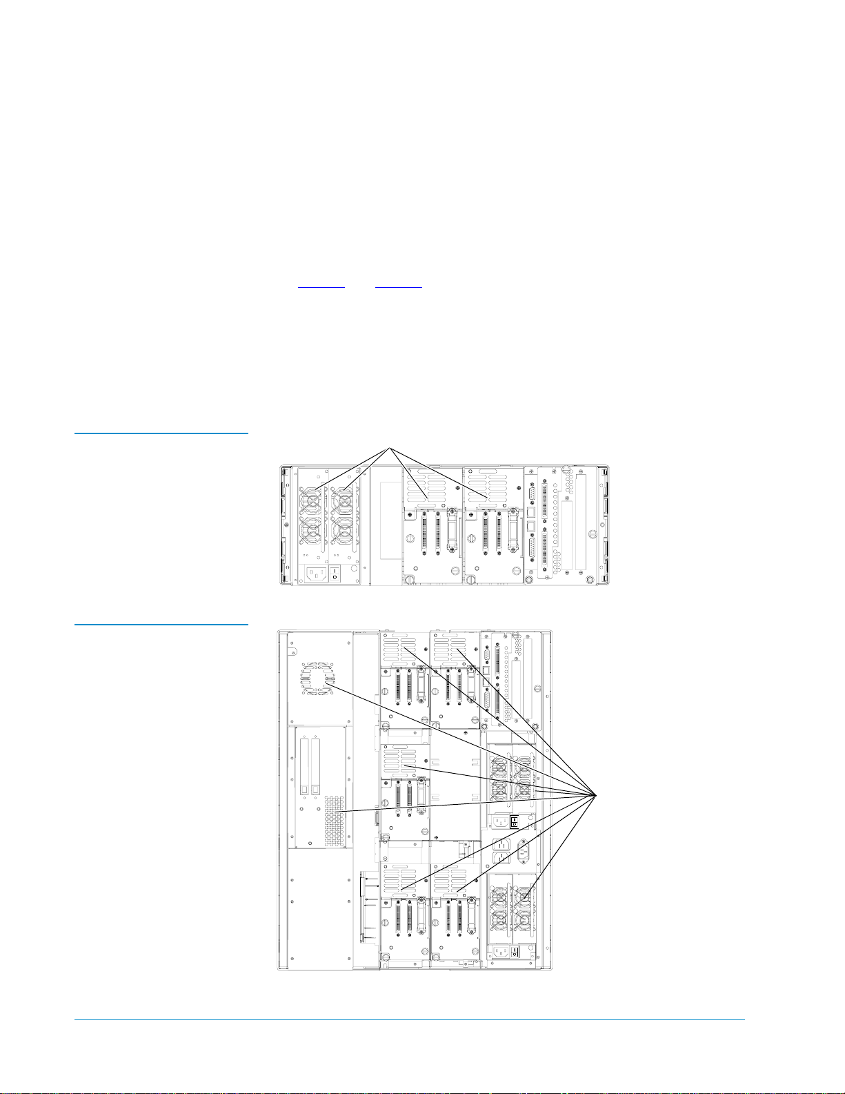
Cooling is one of the most important factors to consider when selecting a
0
location for the library. The M1500 and M2500 libraries are force-cooled: air is
drawn into the library through vents at the lower edge of the front bezel and
M1500 M2500
6.9 in. (176 mm) 23.4 in. (595 mm)
19 in. (482 mm) 19 in. (482 mm)
28.6 in. (726 mm) 28.6 in. (726 mm)
Introduction 3
Tandberg Data M-Series Installation Guide
Vent
Document T6423046-02 A01
February 2004
exhausted through vents at the back of the library. To ensure that the library
is adequately ventilated:
• Place the library on a hard, level surface, or in a standard 19-inch rack.
• If the library will be placed in a rack, the rack must be open or ventilated
• Verify that no cables obstruct the vents at the back of the library (see
• Verify that nothing obstructs the vents at the lower edge of the front
• Allow at least 5 inches (12.7 cm) of space behind the library or rack.
• Do not install the library near a heater or radiator which could warm the
so that the air temperature behind the library at the air outlets is less than
104°F (40°C).
figure 1
and figure 2).
bezel.
air drawn into the library.
Figure 1 Vent Locations,
M1500
Figure 2 Vent Locations,
M2500
s
Vents
4 Site Requirements
Tandberg Data M-Series Installation Guide
Document T6423046-02 A01
February 2004
Environmental Requirements
Power and Grounding
0
0
The installation site (desktop library) or the interior of the rack (rack mount
library) must meet the following environmental requirements:
• Humidity: 20% to 80%, non-condensing
• Temperature: 50°F to 104°F (10°C to 40°C)
• Altitude: -100 to +10,000 feet (-30 to +3,000 meters)
The M1500 and M2500 power supplies accept 88 VAC to 264 VAC input
power at 47 Hz to 63 Hz.
The library must be connected to a grounded power outlet. If the library is
mounted in a rack, the rack must also be grounded.
Installing a Desktop or Deskside Library 0
This section explains how to install a desktop M1500 or a deskside M2500. To
install a rack mount library, see Installing a Rack Mount Library
Note: The procedures in this section assume that you have already
unpacked the library. If you have not, do so now, referring to the
Tandberg M1500 Unpacking Instructions (PN T6421035) or Tandberg
M2500 Unpacking Instructions (PN T6423047).
.
Installing a Desktop M1500
Installing a Deskside M2500
To install a desktop M1500:
0
0
1 Convert the M1500 to a desktop unit by performing the procedures
detailed in the Tandberg M1500 Rack Mount to Desktop Conversion
Instructions (PN T6421036).
This document is provided with the M1500 Rack Mount to Desktop
Conversion Kit.
2 Place the library in the installation location, preferably on a sturdy desk
or tabletop.
3 Proceed to Installing Drives in the Library
installation procedure.
To install a deskside M2500:
1 Convert the M2500 to a deskside unit by performing the procedures
detailed in the Tandberg M2500 Rack Mount to Deskside Conversion
Instructions (PN T6423048).
This document is provided with the M2500 Rack Mount to Deskside
Conversion Kit.
Installing a Desktop or Deskside Library 5
on page 31 to continue the

Tandberg Data M-Series Installation Guide
Document T6423046-02 A01
February 2004
2 Place the library in the installation location.
3 Proceed to Installing Drives in the Library
installation procedure.
on page 31 to continue the
Installing a Rack Mount Library 0
This section explains how to install an M1500 or M2500 in a standard 19-inch
rack.
Note: The procedures in this section assume that you have already
unpacked the library. If you have not, do so now, referring to the
Tandberg M1500 Unpacking Instructions (PN T6421035) or Tandberg
M2500 Unpacking Instructions (PN T6423047).
Determining the Position of the Shelves in the Rack
0
Before starting the rack mount installation:
1 Determine the proper position of the shelves in the rack:
Caution: Take rack stability into account when determining
where to place the library in the rack.
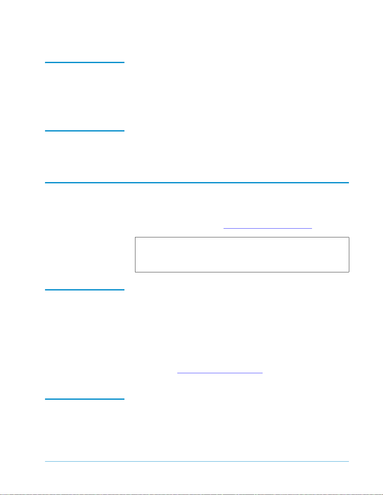
• The rack is measured in rack mount units. Each unit is called a “U,”
and is equal to 1.75 inches (44.45 millimeters). When you look at the
rack rails you will notice that the holes are divided into groups of
three, with each group separated by a slightly smaller space. Each
group of three equally spaced holes is one U (see figure 3
• An M1500 uses 4U of vertical space. The M1500 rack mount shelves
must be installed in a full U position (the bottom of the rack mount
shelf must be aligned with the bottom of a U) (see figure 4
• An M2500 uses 13.5U of vertical space. The M2500 rack mount
shelves can be installed in either a full U or a half U position (the
bottom of the rack mount shelf may be aligned with either the bottom
or the middle of a U) (see figure 5
• The StackLink mounting hardware uses 1U of vertical space at the
top of the rack, and either 1U or .5U at the bottom of the rack (see the
Tandberg M-Series StackLink Installation Instructions, PN T6423049, for
more information).
2 Mark the desired shelf position on the rack rails.
).
).
).
6 Installing a Rack Mount Library

Figure 3 Example of Full
and Half U Mounting
Positions
In the half U position, the bottom of the
mounting bracket aligns with the center of the
middle hole in the corresponding U. This
position can be used for M2500 rack mount
shelves only.
Tandberg Data M-Series Installation Guide
Document T6423046-02 A01
February 2004
3 equally
spaced holes
equals 1 U
1 U
In the full U position, the bottom of the
mounting bracket aligns with the bottom of the
corresponding U. This position can be used
for either M1500 or M2500 rack mount
shelves
Figure 4 M1500 Shelf
Mounting Positions
M1500
Shelf mounting position
4U
Installing a Rack Mount Library 7
Tandberg Data M-Series Installation Guide
Document T6423046-02 A01
February 2004
Figure 5 M2500 Shelf
Mounting Positions
Shelf mounting position (half U position)
Installing the M1500 Rack Mount Shelves
M2500 13.5U
This section explains how to install the M1500 rack mount shelves.
0
Note: To install rack mount shelves for an M2500, see Installing the
M2500 Rack Mount Shelves on page 14.
Checking the Contents of the Rack Mount Kit
M2500
Shelf mounting position (full U position)
13.5U
0
Table 2 lists the contents of the M1500 Universal Rack Mount Kit.
Table 2 Contents, M1500
Universal Rack Mount Kit
Part No. Description Qty.
213467 Shelf clamp 4
213468 Insert (9 sq) 8
213469 Insert (7 sq) 8
213471 Insert (M6) 8
213472 Insert (M5 or 12-24UNC) 8
8 Installing a Rack Mount Library

Tandberg Data M-Series Installation Guide
Document T6423046-02 A01
February 2004
Part No. Description Qty.
213473 Insert (10-32UNF) 8
213474 Insert (1/4" dia) 8
213476 Universal shelf, right 1
213477 Universal shelf, left 1
213478 Shelf extender #1 1
213479 Shelf extender #2 1
YS40403 Plain washer M5 4
YS40403 Plain washer M5 2
YS41720 Button head socket screw 10-24 UNC x 0.5 ins 2
YS41998 Nut, M5 full 4
YS42008 M6 cage nut 2
YS42011 Button head socket screw M6 x 12 2
YS42038 Countersink hex socket screw M4 X 10 LG 4
YS42042 Button head socket screw M5 x 12 2
YS42043 Button head socket screw 10-32 UNC x 0.5 ins 2
YS42044 M5 spire nut 2
Verifying That You Have the Required Tools 0
The following tools are required to install the rack mount kit:
• 8 mm open end wrench
• 2.5 mm socket driver (preferably ball headed)
• Flat blade screwdriver
• Tape measure
Assembling the Rack Mount Shelves
1 Measure the distance between the inside surfaces of the front and rear
rack rails, then find the corresponding rack depth in table 3
.
0
2 Assemble the left shelf:
a Refer to the
Left Shelf/Shelf Extender column of table 3 to determine
which shelf extender to combine with the left universal shelf.
b Insert the posts on the left universal shelf into the shelf extender slots
identified in the
Left Shelf/Slots column of table 3.
The slots in the shelf extenders are identified as shown in figure 6
Installing a Rack Mount Library 9
.

Tandberg Data M-Series Installation Guide
Document T6423046-02 A01
February 2004
c Use the M5 nuts (PN YS41998) and M5 washers (PN YS40403)
provided in the rack mount kit to fasten the left shelf and shelf
extender together (see figure 7
).
Note: Tighten the nuts to finger-tightness only; you need to be able
to retract and extend the assembled shelves slightly.
Table 3 Shelf Assembly
Matrix
3 Assemble the right shelf in the same manner, referring to the
column of table 3
.
Left Shelf Right Shelf
Rack Depth
(between flanges)
24.50 in. - 26.75 in.
Shelf
Extender Slots
#2 A & B #1 A & B
Shelf
Extender Slots
(620 mm - 680 mm)
26.75 in. - 29.125 in.
#1 B & C #2 A & B
(680 mm - 740 mm)
29.125 in. - 31.50 in.
#2 B & C #1 B & C
(740 mm - 800 mm)
31.50 in. - 33.875 in
#1 C & D #2 B & C
(800 mm - 860 mm)
33.875 in. - 36.25 in.
#2 C & D #1 C & D
(860 mm - 920 mm)
Right Shelf
Figure 6 Identifying the
Shelf Extender Slots
A
B
10 Installing a Rack Mount Library
C
D
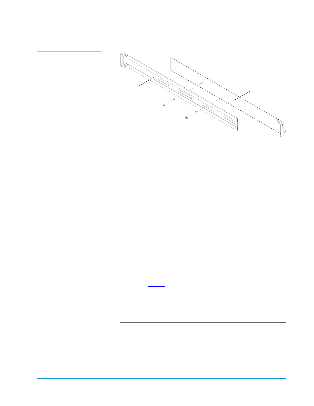
Figure 7 Attaching the
Shelves to the Extenders
Tandberg Data M-Series Installation Guide
Document T6423046-02 A01
February 2004
Extender
Shelf
Installing the Rack Mount Shelves 0
To install the rack mount shelves:
1 From the six sizes of inserts provided in the rack mount kit, select the
insert type that best fits the holes in the rack rails. The insert part
numbers are:
• 213468 (for rails with 9 mm square holes)
• 213469 (for rails with 7 mm diameter unthreaded holes)
• 213471 (for rails with M6 threaded holes)
• 213472 (for rails with M5 or 12-24 UNC threaded holes)
• 213473 (for rails with 10-32 UNF threaded holes)
• 213474 (for rails with 1/4 inch diameter unthreaded holes)
The heads of the inserts (not the threads) should fit into the holes in the
rack rails smoothly and with very little play.
2 Once you have selected the inserts for your rack, set the others aside. You
will not need them for this installation.
3 Screw the inserts into the two outer holes on each end of the assembled
shelves (see figure 8
).
Note: Some of the inserts have either no head or a head that has a
smaller diameter than the thread; these need to be left
protruding by about 1/8 in. (3 mm). The inserts with heads
should be tightened fully.
Installing a Rack Mount Library 11
Tandberg Data M-Series Installation Guide
Document T6423046-02 A01
February 2004
Figure 8 Installing the
Inserts in the Shelves
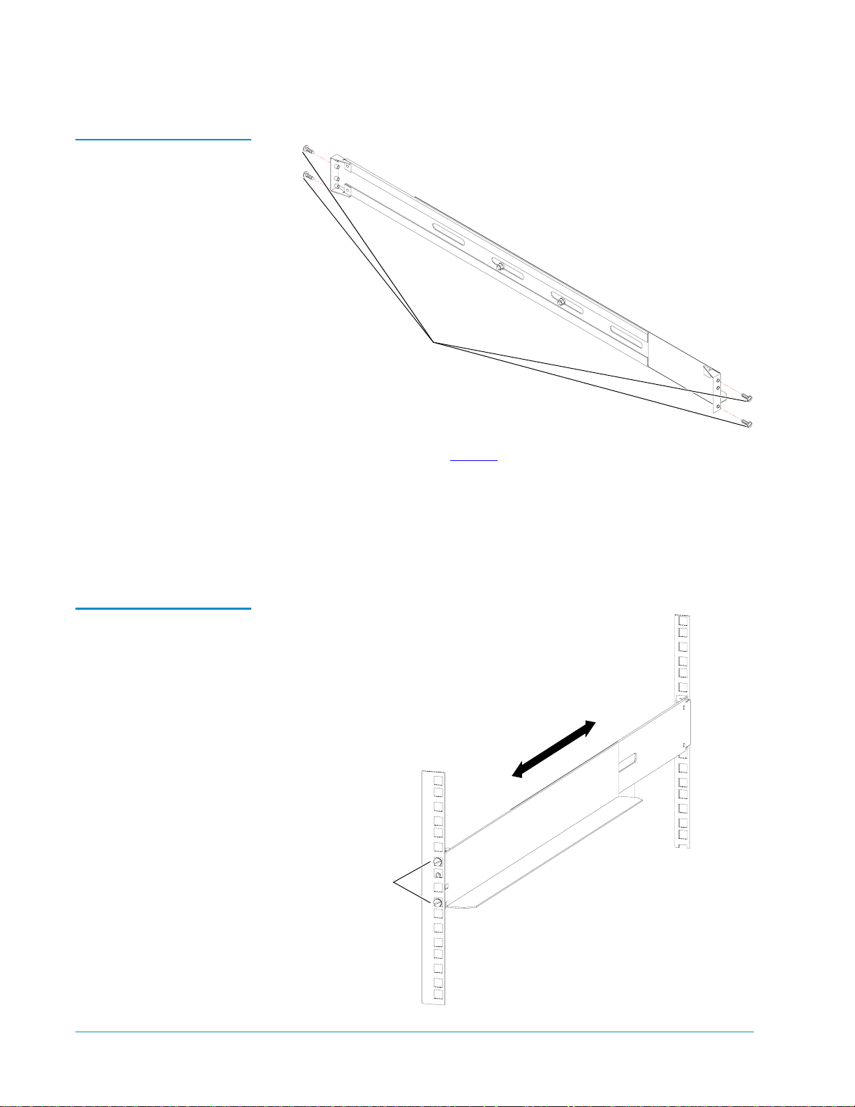
4 Install the left shelf (see figure 9):
Inserts
Figure 9 Installing the
Shelf in the Rack
a With the shelf slightly retracted, position the shelf in the rack at the
desired mounting height.
b Expand the shelf so that the inserts on each end of the shelf protrude
into the holes in the rack rails and hold the shelf in place.
5 Repeat the above steps to install the right shelf.
Inserts protrude
through the
holes in the rails
12 Installing a Rack Mount Library
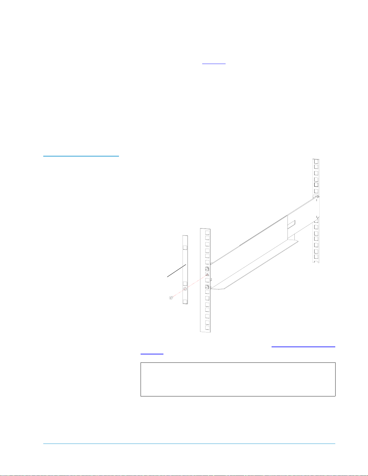
Figure 10 Securing the
Shelf Clamp to the Rail
Tandberg Data M-Series Installation Guide
Document T6423046-02 A01
February 2004
6 Secure the shelves (see figure 10):
a Position a shelf clamp (PN 213467) on the front left rack rail.
The bottom of the shelf clamp should be flush with the bottom of the
shelf.
b Secure the shelf clamp to the rack rail using an M4 countersink screw
(PN YS42038).
c Repeat these steps to install shelf clamps at the front and back of each
shelf.
d Tighten the nuts securing the shelves to the shelf extenders.
Shelf clamp
The shelf installation is now complete. Proceed to Installing the Library in
the Rack on page 28 to install the library.
Note: The universal rack mount kit contains screws and nuts for
many different types of rack. You will have many of these
screws and nuts left over after installing the rack mount
shelves and library.
Installing a Rack Mount Library 13

Tandberg Data M-Series Installation Guide
Document T6423046-02 A01
February 2004
Installing the M2500 Rack Mount Shelves
Table 4 Contents, M2500
Universal Rack Mount Kit
This section explains how to install the M2500 rack mount shelves.
0
Note: To install rack mount shelves for an M1500, see Installing the
M1500 Rack Mount Shelves on page 8.
Checking the Contents of the Rack Mount Kit
Table 4 lists the contents of the M2500 Universal Rack Mount Kit.
Part No. Description Qty.
215812 Front shelf clamp 4
215201/01 Rear shelf clamp 2
213468 Insert (9 sq) 12
213469 Insert (7 sq) 12
213471 Insert (M6) 12
213473 Insert (10-32 UNF, 12-24 UNC, or M5) 12
213474 Insert (1/4 inch diameter) 12
0
217405 Clamp strip 2
215197/02 Universal shelf, right 1
215198/02 Universal shelf, left 1
215199/01 Shelf extender, long #1 1
215200/01 Shelf extender, long #2 1
YS40403 Plain washer M5 8
YS41998 Nut, M5 full 8
YS42064 Countersink hex socket screw M4 x 12 LG 12
Verifying That You Have the Required Tools 0
The following tools are required to install the rack mount kit:
• 8 mm open end wrench
• 2.5 mm socket driver (preferably ball headed)
• Flat blade screwdriver
• Tape measure
14 Installing a Rack Mount Library

Tandberg Data M-Series Installation Guide
Document T6423046-02 A01
February 2004
Assembling the Rack Mount Shelves 0
To assemble the rack mount shelves:
1 Measure the distance between the inside surfaces of the front and rear
rack rails, then find the corresponding rack depth in table 5
.
2 Assemble the left shelf:
Table 5 Shelf Assembly
Matrix
a Refer to the
Left Shelf/Shelf Extender column of table 5 to determine
which shelf extender to combine with the left universal shelf.
b Insert the posts on the left universal shelf into the shelf extender slots
identified in the
Left Shelf/Slots column of table 5.
The slots in the shelf extenders are identified as shown in figure 11
c Use the M5 nuts (PN YS41998) and M5 washers (PN YS40403)
provided in the rack mount kit to fasten the left shelf and shelf
extender together (see figure 12
).
Note: Tighten the nuts to finger-tightness only; you need to be able
to retract and extend the assembled shelves slightly.
3 Assemble the right shelf in the same manner, referring to the
column of table 5
.
Right Shelf
Left Shelf Right Shelf
Rack Depth
(between flanges)
24.25 in. to 26.75 in.
Shelf
Extender Slots
Long #2 A & B Long #1 A & B
Shelf
Extender Slots
(617 mm to 680 mm)
.
26.75 in. to 29.125 in.
Long #1 B & C Long #2 A & B
(680 mm to 740 mm)
29.125 in. to 31.5 in.
Long #2 B & C Long #1 B & C
(740 mm to 800 mm)
31.5 in. to 33.875 in.
Long #1 C & D Long #2 B & C
(800 mm to 860 mm)
33.875 in. to 36.25 in.
Long #2 C & D Long #1 C & D
(860 mm to 920 mm)
Installing a Rack Mount Library 15

Tandberg Data M-Series Installation Guide
Document T6423046-02 A01
February 2004
Figure 11 Identifying the
Shelf Extender Slots
A
Figure 12 Attaching the
Shelves to the Extenders
B
A
C
B
D
C
D
Shelf
D
C
D
B
C
Extender
A
A
B
Installing the Shelves in a Half U Positi on 0
To install the rack mount shelves in a half U position:
Note: The top and bottom libraries in a 3-high M2500 stack are mounted
in a half U position.
1 From the five sizes of inserts provided in the rack mount kit, select the
insert type that best fits into the holes in the rack rails. The heads of the
inserts (not the threads) should fit into the holes in the rack rails smoothly
and with very little play.
The insert part numbers are:
• 213468 (for rails with 9 mm square holes)
• 213469 (for rails with 7 mm diameter unthreaded holes)
• 213471 (for rails with M6 threaded holes)
• 213473 (for rails with 10-32 UNF, 12-24 UNC, or M5 threaded holes)
• 213474 (for rails with 1/4 inch diameter unthreaded holes)
16 Installing a Rack Mount Library
 Loading...