

Page 1
SUPPLEMENT
SERVICE MANUAL
This service manual shows only the differences between
the model LC200SL8 A and the original model LC200SL8.
All other information is described in the service manual
of the model LC200SL8.
20″ COLOR LCD TELEVISION
LC200SL8 A
TABLE OF CONTENTS
Schematic Diagrams / CBA’s and Test Points . . . . . . . . . . . . . . . . . . . . . . . . . . . . . . . . . . . . . . . . . . . 1-1
Different parts from the original model (LC200SL8) . . . . . . . . . . . . . . . . . . . . . . . . . . . . . . . . . . . . . . 2-1
Page 2

SCHEMATIC DIAGRAMS / CBA’S AND TEST POINTS
Standard Notes
WARNING
Many electrical and mechanical parts in this chassis
have special characteristics. These characteristics
often pass unnoticed and the protection afforded by
them cannot necessarily be obtained by using
replacement components rated for higher voltage,
wattage, etc. Replacement parts that have these
special safety characteristics are identified in this
manual and its supplements; electrical components
having such features are identified by the mark “#” in
the schematic diagram and the parts list. Before
replacing any of these components, read the parts list
in this manual carefully. The use of substitute
replacement parts that do not have the same safety
characteristics as specified in the parts list may create
shock, fire, or other hazards.
Notes:
1. Do not use the part number shown on these
drawings for ordering. The correct part number is
shown in the parts list, and may be slightly
different or amended since these drawings were
prepared.
2. All resistance values are indicated in ohms
(K = 10
3. Resistor wattages are 1/4W or 1/6W unless
otherwise specified.
4. All capacitance values are indicated in µF
(P = 10
5. All voltages are DC voltages unless otherwise
specified.
3
, M = 106).
-6
µF).
1-1 LC4N_SC
Page 3
LIST OF CAUTION, NOTES, AND SYMBOLS USED IN THE SCHEMATIC DIAGRAMS ON
THE FOLLOWING PAGES:
1. CAUTION:
CAUTION: FOR CONTINUED PROTECTION AGAINST RISK OF FIRE, REPLACE ONLY WITH SAME
TYPE_A,_V FUSE.
ATTENTION: UTILISER UN FUSIBLE DE RECHANGE DE MÊME TYPE DE_A,_V.
2. CAUTION:
Fixed Voltage (or Auto voltage selectable) power supply circuit is used in this unit.
If Main Fuse (F601) is blown, first check to see that all components in the power supply circuit are not
defective before you connect the AC plug to the AC power supply. Otherwise it may cause some components
in the power supply circuit to fail.
3. Note:
1. Do not use the part number shown on the drawings for ordering. The correct part number is shown in the
parts list, and may be slightly different or amended since the drawings were prepared.
2. To maintain original function and reliability of repaired units, use only original replacement parts which are
listed with their part numbers in the parts list section of the service manual.
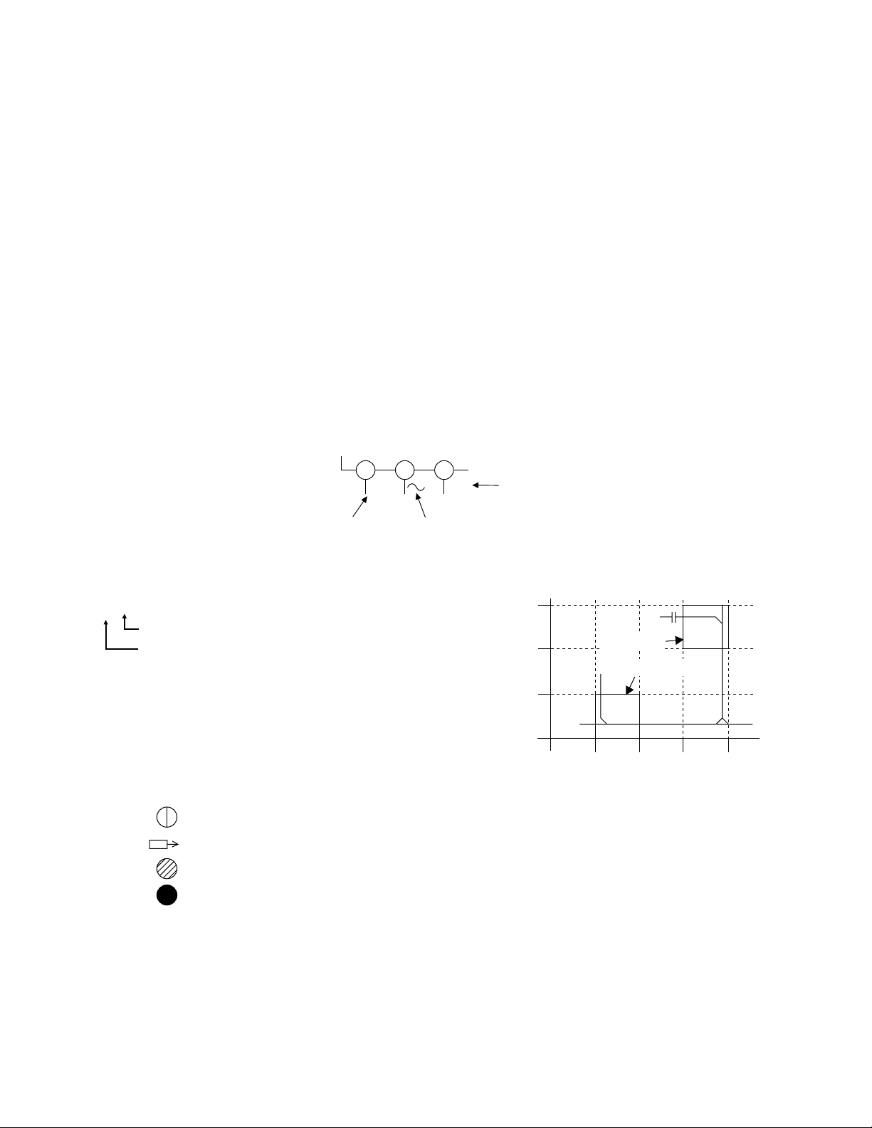
4. Voltage indications on the schematics are as shown below:
Plug the TV power cord into a standard AC outlet.:
2
(Unit: Volt)
1
5.0 5.0
3
Power on mode
5. How to read converged lines
1-D3
Distinction Area
Line Number
(1 to 3 digits)
Examples:
1. "1-D3" means that line number "1" goes to the line number
"1" of the area "D3".
2. "1-B1" means that line number "1" goes to the line number
"1" of the area "B1".
6. Test Point Information
: Indicates a test point with a jumper wire across a hole in the PCB.
: Used to indicate a test point with a component lead on foil side.
: Used to indicate a test point with no test pin.
: Used to indicate a test point with a test pin.
Voltage
Indicates that the voltage
is not consistent here.
3
2
1
AREA D3
1-B1
AREA B1
1-D3
ABCD
1-2 LC4N_SC
Page 4

Main 1/5 Schematic Diagram
2 24.4
3 24.4
40
53.3
63.3
70
8 10.8
90
10 -6.2
11 0
12 1.2
13 0.7
14 0.5
15 0.7
16 1.3
17 1.1
18 0
19 1.2
20 0.9
21 0.7
22 0.8
23 0
24 0
25 0
26 0
27 0
28 2.1
29 0
30 1.3
31 1.3
32 0
33 0
CN1201
11.2
21.0
30.8
40.7
51.0
61.4
70
81.2
90
10 1.2
11 0.7
12 0.5
13 0.7
14 1.3
15 1.1
16 0
17 1.2
18 0.9
19 0.7
20 0.7
21 1.3
22 1.3
23 0
24 1.2
25 1.0
26 0.9
27 0.8
28 1.0
29 1.4
30 0
31 0
32 1.7
33 0.3
34 3.4
35 1.7
CN1202
10
VOLTAGE CHART
Pin No. Voltage
Pin No. Voltage
1-3
A7148SCM1
Page 5

Main 2/5 Schematic Diagram
CN61
10
21.1
35.2
43.1
53.2
60
72.9
83.2
91.7
10 0.1
11 0
12 3.4
13 0
14 3.1
15 3.1
CN62
1---
23.3
30
43.4
52.6
61.9
7--80
90
10 0
11 0
12 0
13 0
14 --15 2.6
16 2.6
17 0
18 ~
19 ~
20 ~
VOLTAGE CHART
Pin No. Voltage
Pin No. Voltage
1-4
A7148SCM2
Page 6

Main 5/5 Schematic Diagram
CAUTION !
Fixed voltage (or Auto voltage selectable) power supply circuit is used in this unit.
If Main Fuse (F601) is blown , check to see that all components in the power supply
circuit are not defective before you connect the AC plug to the AC power supply.
Otherwise it may cause some components in the power supply circuit to fail.
4A/125V
CAUTION ! :
ATTENTION : Utiliser un fusible de rechange de même type de 4A, 125V.
For continued protection against risk of fire,
replace only with same type 4 A, 125V fuse.
NOTE:
The voltage for parts in hot circuit is measured using
hot GND as a common terminal.
1-5
A7148SCM5
Page 7

Function Schematic Diagram
1-6
A7148SCF
Page 8

Different parts from the original model (LC200SL8)
Ref. No. Description Part No.
MECHANICAL PARTS
A6# RATING LABEL A7148UH ---------LCD1 LCD MODULE LC5 20INCH CPT UF200XC
ELECTRICAL PARTS
MAIN CBA 1ESA14462
C84 CHIP CERAMIC CAP.(1608) F Z 0.1µF/25V CHD1EZ30F104
C791 CERAMIC CAP.(AX) B K 100pF/50V CCA1JKT0B101
C995 ELECTROLYTIC CAP. 100µF/16V M CE1CMASDL101
C1006 Not used
C1217 ELECTROLYTIC CAP. 100µF/16V M CE1CMASDL101
C1219 ELECTROLYTIC CAP. 100µF/16V M CE1CMASDL101
C1374 CHIP CERAMIC CAP.(1608) CH J 22pF/50V CHD1JJ3CH220
D475 SWITCHING DIODE 1SS133(T-77) QDTZ001SS133
D908 ZENER DIODE MTZJT-7715B QDTB00MTZJ15
D1006 SWITCHING DIODE 1SS133(T-77) QDTZ001SS133
D1205 Not used
D1325 ZENER DIODE MTZJT-774.3B QDTB0MTZJ4R3
R950 CARBON RES. 1/4W J 150k Ω RCX4JATZ0154
R1007 CARBON RES. 1/4W J 56 Ω RCX4JATZ0560
R1009 CHIP RES. 1/10W F 10k Ω RRXAFR5H1002
R1010 CHIP RES. 1/10W F 4.7k Ω RRXAFR5H4701
R1024 Not used
R1025 CARBON RES. 1/4W J 10 Ω RCX4JATZ0100
R1026 CARBON RES. 1/4W J 10 Ω RCX4JATZ0100
R1027 CARBON RES. 1/4W J 10 Ω RCX4JATZ0100
R1028 CARBON RES. 1/4W J 10 Ω RCX4JATZ0100
R1029 CARBON RES. 1/4W J 10 Ω RCX4JATZ0100
B17 CLOTH(10X30XT0.5) B5900UA 0EM404486
TU61 TUNER UNIT U4002AF UTUNATSSP001
FUNCTION CBA ---------C1103 CERAMIC CAP.(AX) Y M 0.01µF/16V CCA1CMT0Y103
20070320 2-1 A7148PL
Page 9

© 2007 Funai Electric Co., Ltd.
All rights reserved. No part of this manual may be reproduced, copied, transmitted, disseminated, transcribed,
downloaded or stored in any storage medium, in any form or for any purpose without the express prior written
consent of Funai. Furthermore, any unauthorized commercial distribution of this manual or any revision hereto
is strictly prohibited.
Information in this document is subject to change without notice. Funai reserves the right to change the content
herein without the obligation to notify any person or organization of such changes.
with the design is a registered trademark of Funai Electric Co., Ltd and may not be used in any way
without the express written consent of Funai. All other trademarks used herein remain the exclusive property of
their respective owners. Nothing contained in this manual should be construed as granting, by implication or
otherwise, any license or right to use any of the trademarks displayed herein. Misuse of any trademarks or any
other content in this manual is strictly prohibited. Funai shall aggressively enforce its intellectual property rights
to the fullest extent of the law.
LC200SL8 A
A7148UH
2007-03-28
 Loading...