


Summit SBC635MBINKIF, SBC635MBINKSSHH, SBC635MBI, SBC635MBINKFR, SBC635MBINKSSHV User Manual
...BEER DISPENSER
DISTRIBUTEUR de BIÈRE
Models / Modèles SBC635MBI
SBC635MOS
Use and Care Guide
Mode d’emploi
BEFORE USE, PLEASE READ AND FOLLOW ALL SAFETY RULES AND
OPERATING INSTRUCTIONS.
Keep proof of original sales date (such as your sales slip) with this manual to establish the warranty period.
Write the Serial Number below. You’ll find it on a plate located either on the back of the appliance or on an interior wall.
__________________________________________________
AVANT UTILISATION, S'IL VOUS PLAÎT LIRE ET SUIVRE LES RÈGLES DE SÉCURITÉ ET INSTRUCTIONS D'UTILISATION.
Conserver une preuve de la date d'achat d'origine (comme votre ticket de caisse) avec ce manuel pour établir la période de garantie.
Écrire numéro de série ici. Vous le trouverez sur une plaque située soit sur l’arrière de l'appareil ou sur un mur intérieur.
__________________________________________________
Felix Storch, Inc.
770 Garrison Avenue Bronx, NY 10474 www.summitappliance.com
0

TABLE OF CONTENTS
Important Safeguards .................................................................................. |
2 – 3 |
Location of Parts ................................................................................................ |
4 |
Before Using for the First Time ......................................................................... |
4 |
Placement and Installation ........................................................................ |
5 - 11 |
Choosing the right place ............................................................................ |
5 |
Installation ................................................................................................. |
5 |
Applications ............................................................................................... |
5 |
Connecting to power supply ...................................................................... |
5 |
Installing Model SBC635MBI as a built-in unit ..................................... |
6 - 7 |
Reversing the door swing .......................................................................... |
8 |
Installation of accessories ................................................................. |
9 – 11 |
Operation ................................................................................................... |
12– 14 |
Control panel ........................................................................................... |
12 |
Setting the temperature ........................................................................... |
12 |
Switching between Celsius and Fahrenheit ............................................. |
12 |
‘Rapid Cooling’ function ........................................................................... |
12 |
Automatic defrosting ................................................................................ |
13 |
Error prompts ........................................................................................... |
13 |
Normal functioning ................................................................................... |
13 |
Dispensing beer ............................................................................... |
13 – 14 |
Understanding beer temperature ............................................................. |
14 |
Beer serving tips ...................................................................................... |
14 |
Maintenance of the Beer Dispenser ................................................................ |
15 |
Cleaning .................................................................................................. |
15 |
Out of service .......................................................................................... |
15 |
Transporting the unit ................................................................................ |
15 |
Specifications of beer kegs ...................................................................... |
15 |
Disposing of a Worn-Out Appliance ............................................................... |
16 |
Draft Beer Troubleshooting ...................................................................... |
17– 18 |
General Troubleshooting ................................................................................. |
19 |
Limited Warranty .............................................................................................. |
20 |
French version of this manual ................................................................. |
2143 |
1

IMPORTANT SAFEGUARDS
WARNING!
To reduce the risk of fire, electric shock or injury when using this appliance, follow these basic precautions:
1.Read all instructions before using the appliance.
2.The appliance must be correctly connected to the power supply.
3.Immediately replace worn power cords, loose plugs and faulty power outlets.
4.Do not operate your appliance in the presence of explosive fumes.
5.Disconnect the appliance from the power supply before cleaning or repairing it. Only a qualified technician should repair it.
6.Never stand on top of or inside this appliance, or swing on the door. Avoid putting weight on top of the appliance.
7.To reduce likelihood of injury, do not let children play with this appliance.
8.Do not operate the valve control unless the cylinder is completely installed and connected.
9.Do not attempt to repair or replace any part unless this is recommended in this Use and Care Guide. Leave other service matters to qualified technical personnel.
10.Keep packing materials away from children as they could become a choking hazard.
11.Do not spray or flush the beer dispenser with water, and avoid keeping it in a damp place since this could damage the electrical insulation.
DANGER! Risk of child entrapment!
Child entrapment and suffocation are not problems of the past. Junked or abandoned appliances are still dangerous, even if they will "just sit at the curb for a few days."
Before discarding your old appliance:
•Take off the door.
•Leave the shelves in place so that children may not easily climb inside.
•This appliance is CFCand HFC-free and contains small quantities of Isobutane (R600a) which is environmentally friendly, but flammable. It does not damage the ozone layer, nor does it increase the greenhouse effect. Care must be taken during transportation and setting up of the appliance that no parts of the cooling system are damaged. Leaking coolant can ignite and may damage the eyes.
In the event of any damage:
-Avoid open flames and anything that creates a spark,
-Disconnect from the electrical power line,
-Air the room in which the appliance is located for several minutes, and
-Contact the Service Department for advice.
•The more coolant there is in an appliance, the larger the room it should be installed in. In the event of a leakage, if the appliance is in a small room, there is the danger of combustible gases building up. For every ounce of coolant at least 325 cubic feet of room space is required. The amount of coolant in the appliance is stated on the data plate on the back of the appliance. It is hazardous for anyone other than an Authorized Service Person to carry out servicing or repairs to this appliance.
•Take serious care when handling, moving, and using the appliance to avoid either damaging the refrigerant tubing or increasing the risk of a leak.
•Replacing component parts and servicing shall be done by factory authorized service personnel so as to minimize the risk of possible ignition due to incorrect parts or improper service.
2
SAFETY PRECAUTIONS: ELECTRICAL MATTERS
1.Do not pull on the power cord when unplugging the machine. Grasp the plug firmly and pull it straight out of the socket. Do not pull the plug with wet hands.
2.Keep the power cord at the back of the appliance to avoid tripping accidents or damage to the cord.
3.If the power cord is damaged or frayed, it must be replaced by a qualified service professional.
4.Use only a standard three-hole grounded power socket rated above 10A. The socket should not be shared with other appliances.
5.Be sure the plug fits firmly into the socket and that the socket is grounded.
6.The use of an extension cord is NOT recommended.
7.The beer dispenser requires an AC power supply of 110~120V/60Hz and pulls a current of over 10A. The fuse or circuit breaker should be rated at 15A.
8.If the leakage of a combustible gas is detected, turn off the gas valve and open the doors and windows. To reduce the risk of fire caused by a spark, do not pull out the plug of the beer dispenser or of any other electrical device.
SAFETY PRECAUTIONS: CO2 (CARBON DIOXIDE) GAS
Always connect the CO2 cylinder to a regulator! Failure to do so may cause an explosion resulting in possible injury or death when the cylinder valve is opened.
Never connect the CO2 cylinder directly to the product container.
Always keep CO2 cylinders away from heat. Store extra cylinders in a cool place (preferably below 70°F). Securely fasten cylinders with a chain in an upright position when storing.
Never drop or throw a CO2 cylinder.
Always check the D.O.T. (Department of Transportation) test date on the cylinder neck before installation. If it has been more than 5 years, do not use. Return the cylinder to your gas supplier.
Never connect a product container unless there are at least two safety devices in the pressure system: one on the CO2 regulator and the other on the product container or in the pressurized gas line.
The recommended pressure for the CO2 system is 8-10 lbs.
SAVE THESE INSTRUCTIONS
Model SBC635MBI is designed for indoor use and can be installed either built-in or free-standing.
Model SBC635MOS can be installed in an outdoor environment. It can only be installed free-standing. Do not use under a bar or counter. This model is equipped with a GFCI (ground-fault circuit interrupter) plug, a safety device that cuts off electricity to the unit if the power line gets wet.
To save energy and maintain optimum performance:
When positioning the OS unit: Allow at least 4 inches of clearance at the top, on the sides and in the rear for sufficient airflow.
3
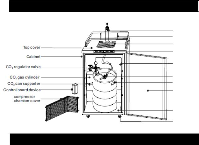
LOCATION OF PARTS
|
|
|
|
|
|
|
|
|
|
|
|
|
|
|
|
|
|
|
|
|
|
|
Beer tower assembly |
|
|
|
|||||
|
|
|
|
|
|
|
|
|
|
|
|
|
|
|
|
|
|
|
|
|
|
|
|
|
Upper cover guardrail |
|
|
|
|||
|
|
|
|
|
|
|
|
|
|
|
|
|
|
|
|
|
|
|
|
|
|
|
|
|
|
|
|
|
|
|
|
|
|
|
|
|
|
|
|
|
Drip tray |
|
|
|
|||
|
Top cover |
|
|
|
|
|
|
|
|
|
|
|
|
||
|
|
|
|
|
|
|
|
|
|||||||
|
|
|
Display and control |
|
|
|
|||||||||
|
|
|
|
|
|
|
|
|
|
|
|
|
|||
|
|
|
|
|
|
|
|
|
|
|
|
|
|||
|
|
|
|
|
|
|
|
|
|
panel |
|
|
|
||
|
Cabinet |
|
|
|
|
|
|
|
|
|
|
|
|||
|
|
|
|
|
|
|
|
|
|
|
|
|
|||
|
|
|
|
|
|
|
|
|
|
|
|
|
|
|
|
|
|
|
|
|
|
|
|
|
|
|
|
|
|
|
|
|
|
|
|
|
|
|
|
|
|
Evaporator |
|
|
|
||
|
CO2 regulator valve |
|
|
|
|
|
|
|
|
|
|
|
|||
|
|
|
|
|
|
|
|
|
|||||||
|
|
|
|
|
|
|
|
|
|
|
|
|
|
||
|
|
|
|
|
|
|
|
|
|
|
|
|
|
||
|
|
|
Ball valve |
|
|
|
|||||||||
|
CO2 gas cylinder |
|
|
|
|
|
|
|
|||||||
|
|
|
|
|
|
|
|
|
|
|
|
|
|
|
|
|
|
|
|
|
|
|
|
|
|
|
Beer keg |
|
|
|
|
|
CO2 tank supporter |
|
|
|
|
|
|
|
|
|
|
||||
|
|
|
|
|
|
|
|
|
|
|
|||||
|
|
|
|
|
|
|
|
|
|
|
|
|
|||
|
|
|
|
|
|
|
|
|
|
|
|
|
|||
|
Control board device |
|
|
|
|
|
|
|
|
|
|||||
|
|
|
|
|
Door |
|
|
|
|||||||
|
|
|
|
|
|
|
|
|
|
|
|
|
|
|
|
|
|
|
|
|
|
|
|
|
|
|
|
|
|
|
|
|
|
|
|
|
|
|
|
|
|
|
|
||||
|
Compressor |
|
|
|
|
|
|
|
|
|
|||||
|
chamber cover |
|
|
|
|
|
|
|
|
|
|
||||
|
|
|
|
|
|
|
|
|
|
|
|
|
|
|
|
|
|
|
|
|
|
|
|
|
|
|
|
|
|
|
|
|
|
|
|
|
|
|
|
|
|
|
Bottom pad |
|
|
|
|
|
|
|
|
|
|
|
|
|
|
|
|
|
|
|
|
|
|
|
|
|
|
|
|
|
|
|
|
|
|
|
|
|
|
|
|
|
|
|
|
|
|
|
|
Caster |
|
|
|
|
|
|
|
|
|
|
|
|
|
|
|
|
|
|
|
BEFORE USING FOR THE FIRST TIME
The SBC635M series is designed for dispensing beer only, and is not recommended for storing perishable foods such as meats or dairy products.
Before connecting the appliance to the power supply, leave it standing for 2 to 3 hours. This allows the refrigerant to drain back into the compressor and reduces the risk of malfunctions in the cooling system caused by shipping.
Clean the appliance thoroughly, especially the interior. (See Maintenance of the Beer
Dispenser.) Proper grounding must be ensured to reduce the risk of shock and fire. Do not cut or remove the grounding plug!
TIPS FOR SAVING ENERGY
Try not to open the door too often, especially when the weather is hot and humid. Once you open the door, try to close it as soon as possible.
If possible, disconnect the power before changing a keg of beer. Keep the unit out of direct sunlight.
Periodically, check that the beer dispenser seals well and that none of the contents prevent the door from closing.
4

PLACEMENT AND INSTALLATION
Choosing the Right Place
To ensure that your beer dispenser works at the maximum efficiency it was designed for, install it in a location where there are proper air circulation and electrical connections.
Choose a location where the beer dispenser will be away from any heat sources and will not be exposed to direct sunlight.
Remove all packing materials before using the beer dispenser. Place the machine on a smooth, flat and sturdy surface.
Installation
CAUTION:
After unpacking, you MUST allow this appliance to stand upright for at least 2 hours to allow the lubricant and refrigerant to drain back into the compressor and stabilize. Failure to do so may adversely affect performance and the lifetime of this unit.
Model SBC635MOS is not designed to operate in enclosed spaces. When placing your unit, make sure you allow at least 4” of clearance at the sides, rear and top to allow for adequate airflow. It is suitable for outdoor use.
Model SBC635MBI is designed for indoor use only. It can be installed either built-in or freestanding. For built-in installation, you must provide the following clearances around the unit for best operation and proper ventilation: 3/16” on both sides, 2” at the rear and 1/16” at the top. Take care that the air vent at the front of the beer dispenser is never covered or blocked in any way. For free-standing installation, follow the clearances mentioned above for the OS model and be sure no air vents are blocked.
Applications
The SBC635MBI and OS beer dispensers meet UL Standards 250 and 471 and are suitable for residential or commercial use.
Connecting to Power Supply
Connect the appliance to a 3-prong power supply socket (which has a ground terminal). If you only have a two-prong outlet, have it replaced by a qualified technician with an outlet that meets the local codes.
DO NOT USE AN EXTENSION CORD
Required nominal voltage and frequency are indicated on the rating plate. The connection to the power supply and grounding has to be made according to current standards and
regulations. The appliance resists temporary voltage fluctuations with a tolerance of ±10%.
Outdoor model SBC635MOS is fitted with a GFCI safety plug to prevent short circuits during wet conditions.
Once connected, allow the appliance to operate empty for two to three hours before putting a beer keg inside.
5
Installing Model SBC635MBI as a Built-In Unit
This beer dispenser is designed to be built in under your counter (although it can also be used free-standing). Simply follow the steps below for a quick and easy installation.
NOTE: Not all models have built-in capability. Only models with letters BI are built-in compatible. We do not advise that other models be built in under your counter.
33-9/16” MIN.
24¾”MIN.
The dimensions of your unit are:
Height: 33½” (adjustable to 34½" with leveling legs)
Width: 24" *
Depth: 25⅜”
* Allow 1” extra for door to swing completely open (1¼” for stainless steel doors)
24¼”MIN.
Make sure the available space is adequate. Allow at least 3/16” clearance on both sides, 2” at the rear, and 1/16” at the top. Be sure that airflow under the appliance is not blocked.
6
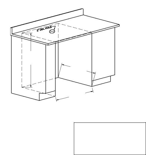
Instructions for Building-In
Find the mid-point:
From left to right the width is about 24¼". From back to front, the dimension is about 25 ⅜". Therefore the mid-point is located wherever these coordinates cross each other. Use a pencil or marker to note this spot.
Note: 12⅛ inches from left to midpoint.
12⅛ inches from right to mid-point 12-11/16 inches from front to mid-point.
Drill a round hole:
Place a drill bit on the mid-point and make a round hole with a diameter of 1⅞".
Installation:
See Installation instructions in this manual.
7
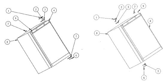
Reversing the Door Swing
|
|
|
|
|
|
|
|
|
|
|
|
|
|
|
|
|
|
|
|
|
|
|
|
|
|
|
|
Figure 1 (Default position) |
|
Figure 2 (After door reversal) |
||||
1. |
Upper hinge cover |
6. |
Screws |
|||
2. |
Screws |
7. |
Hole cover |
|||
3. |
Upper hinge |
8. |
Cabinet |
|||
4. |
Door |
9. |
Pin cap |
|||
5. |
Lower door hinge |
|
|
|
|
|
The beer dispenser can be opened from either the right side or the left. By default, the door hinge is on the right side. If you prefer it on the left, please follow these instructions:
Note: All of the parts that are removed must be kept for the reinstallation of the door.
1.Remove the three screws (6) holding lower door hinge (5). Keep hinge for later use.
2.Remove the door from the upper hinge (3), and keep the padded surface upward to prevent scratching.
3.Remove the upper hinge cover (1), remove the two screws (2), remove the upper hinge (3) and keep it for later use.
4.Remove the hole cover (7) and transfer it to the same location on the opposite side.
5.Insert the lower door hinge (5) into the left side, fixing the hinge into place by tightening all the screws (6).
6.Remove the pin cap (9) from the left side of the upper door frame and then transfer it to the same location on the opposite side.
7.Set the door on the lower door hinge (5), keep the door level, then fix the upper hinge (3) to the body (8) by the screws (2).
8.Put on the upper hinge cover (1).
8

Installation of Accessories
Diagram of overall structure
Drip tray
Soft red CO2 tube
Beer keg handle
Beer keg
Installation components
Tap handle
Draft beer tap
|
CO2 tank bracket and bolt |
|
|
|
|||
CO2 hose clamp |
|
Drip tray assembly |
|
|
|
|
|
|
|
|
|
Installation steps
1. Install universal wheels:
Lock braking guidelines for universal wheels with foot brakes (See Figure 1):
Install the two universal wheel washers at the front of the cabinet base, and then install two universal wheels without foot brakes. Next, install the two universal wheels with foot brakes at the back of the cabinet base. Once installed these rear wheels will keep the unit from moving if you step on the foot brakes (See Figure 2):
9
2.Install the beer tower assembly and the mixed ball valve:
a)Plug the beer tower assembly into the top cover of the beer dispenser:
3.0” tower: This does not require a tower buckle. Put beer tower directly over the hole at the top of the beer dispenser’s upper surface. Fix the beer tower assembly with screws directly on the upper surface of the beer dispenser. (See Fig. 3).
2.5” tower: This requires the tower buckle.
Place the beer tower at the hole in the upper surface of the beer dispenser at an
inclination of 60°, and rotate 60° clockwise along the card slot. Be sure the tap is facing toward the front of the machine. Attach the beer tower with washers (See Figure 4).
b)Take out the accessories of the mixed ball valve. Attach the transparent hose to the beer outlet of the mixed ball valve (See Figure 5).
3.Install CO2 gas cylinder and CO2 regulator valve:
a)Fix the two CO2 hose clamps on the red CO2 tube (See Figure 6).
b)Connect the ends of the red CO2 tube respectively to the CO2 intake port of the mixed ball valve and the round outlet of
the CO2 regulator valve. Lock these connections firmly with the two clamps on the red CO2 tube (See Figure 7).
|
|
|
|
|
Regulating |
|
|
CO2 regulator |
|
|
|||
|
|
|
|
table |
||
|
valve |
|
|
|
||
|
|
|
|
|
|
|
|
|
|
|
|
|
|
|
Safety switch |
|
|
|
||
|
Red CO2 tube |
|
|
|
CO2 gas |
|
|
|
|
|
|
|
cylinder |
|
|
|
|
|||
Bracket and retainer |
|
|
|
|||
of CO2 tank |
|
|
|
|||
c) Using the wrench, tighten the CO2 regulator table valve with the hex nut port to the gas outlet of the CO2 tank (See Figure 8).
d) Place the CO2 tank and CO2 regulator valve component into the cabinet and fix the CO2 tank
with tank bracket and bolt (See Figure 8).
10
4. Install the beer keg:
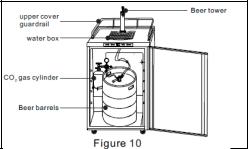
Place the beer keg into the cabinet and firmly connect the keg’s opening to the connection port of the mixed ball valve (See Figure 10).
Note: To place a keg into the cabinet, use the keg handle to move the keg to the front of the open beer dispenser, then carefully tip the keg
so that the raised bottom edge contacts the edge of the cabinet. Finally, lift the keg handle to raise the keg to the level of the floor of the cabinet and push the keg into place.
5. Install tap handle and beer tap:
Screw the tap handle clockwise into the beer tap to make a firm connection. Then connect the tap to the beer tower components and tighten with a wrench (See Figure 9).
6. Install upper cover guardrail and drip tray:
Set the upper cover guardrail and drip tray on top of the beer dispenser (See Figure 10).
Notes:
•When replacing the beer keg, first turn off the safety switch on the CO2 regulator valve and remove the mixed ball valve to take out the keg.
•When replacing the CO2 gas cylinder, remember to turn off the main switch of the CO2 gas cylinder and the safety switch on the CO2 regulator valve. Afterwards, use a wrench to loosen the hexagonal nut port connecting the CO2 regulator valve with the CO2 tank. Then, using a wrench, remove the fixed bolt of the CO2 tank to take out the CO2 tank.
•During the installation process, be sure that all parts are connected tightly and that there are no gas leaks.
•When connecting the hose to the connection port, you can dip the ends into warm water to make the connection easier.
•If the high-pressure compressed gas in the CO2 tank is not handled properly, it could be dangerous:
a.Make a note of the D.O.T. testing date on the cylinder neck before installation. If it is more than 5 years old, don’t use the product. Return it to the gas supplier.
b.Keep gas cylinder away from heat sources. Unused cylinders should be placed upright in a cool, ventilated place (preferably at 70°F).
11
OPERATION
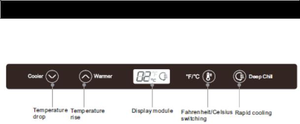
Control Panel
The control panel is located just above the door, and looks like this:
DOWN: Lowers |
UP: Raises |
Display module |
Fahrenheit/Celsius |
Rapid |
temperature |
temperature |
|
switching |
cooling |
|
|
|
|
|
Setting the Temperature
Adjust the DOWN or UP button on the control panel until the display module shows the desired temperature.
The display module shows the set temperature, and the temperature-controlled range varies from 32 to 50°F (0 to 10°C).
The display module shows 5°C at the initial power up. Each press of the DOWN or UP button decreases or increases the temperature displayed by 1°C (1°F).
The optimal temperature for the storage and distribution of beer is 34 - 38°F (1.1 to 3.3°C.
Switching between Celsius and Fahrenheit
You can switch between a Celsius and Fahrenheit temperature display by pressing the °F/°C button. When the displayed temperature is in Celsius, the “°C” symbol will be illuminated; with a Fahrenheit display, “°F” will be illuminated.
‘Rapid Cooling’ Function
Press the Deep Chill button to enter the Rapid Cooling state. The “rapid cooling” icon on the display module will light and the temperature display will read “00”. After entering the Rapid Cooling mode, the appliance will work continuously for 24 hours and the icon will remain lit. After that time, the icon will turn off and the appliance will return to its former state.
You can cancel the Rapid Cooling mode any time during the 24 hour period by simply pressing the Deep Chill button again.
Note: The Rapid Cooling function is normally used only for cooling the first keg of beer in the appliance, when that keg is to be used as soon as possible. To prevent overcooling the beer, do not use Rapid Cooling for succeeding kegs.
12
Automatic Defrosting
There is usually no need to defrost the beer dispenser because the ice deposited on the inner back wall is automatically defrosted. Ice deposits on the inner back wall during compressor operation. Later on, when the compressor is not operating, the ice defrosts and water drains through the outlet in the inner back wall into the drain pan situated above the compressor where it evaporates. If you see water building up in the rear of the unit, check that the drain trough is not clogged. Use a pipe cleaner or a piece of flexible wire. During extremely hot and humid weather, some ice may build up. If necessary, remove contents of the beer dispenser, unplug the unit and allow defrosting. A hair dryer may facilitate the process.
Error Prompts
When the following prompts appear in the display module, there is a failure in the appliance. Although one of the fault conditions occurs, the beer dispenser may still work. However, you should contact our Service Department as soon as possible to obtain advice on handling the situation.
Prompt |
E1 |
E4 |
E7 |
Fault |
Temperature sensor |
Defrosting sensor |
Ambient |
failure in the |
failure in the refrigerator |
temperature |
|
|
refrigerated zone |
compartment |
sensor fault |
Note: When two or more sensors fail simultaneously, all fault codes will display alternately on the display module. If the ambient temperature and defrost sensors fail, any key may be pressed. The temperature is adjustable. The fault display will be restored after 15 seconds.
Normal Functioning
•If there is a sound of rushing water when the machine is in use, the noise is caused by the refrigerant flowing in the cooling pipes and running through the compressor. This is a normal phenomenon.
•The beer dispenser has no heating function. When the temperature is set higher than the ambient temperature, the machine will not run.
Dispensing Beer
Follow these steps to dispense beer:
1.Make sure the beer dispenser is plugged in properly to a 120V, 60Hz, 15 amp grounded AC outlet.
2.Place the drip tray under the beer tap.
3.Open the beer faucet by pulling the tap towards you quickly and completely to dispense the beer.
4.Increase the pressure if the beer runs too slowly. At the correct pressure and temperature, a 10-oz glass should be filled in 4 seconds.
13
 Loading...