

Page 1
SE 300 / SX 300 / SX 400
Notice Originale
Original Instructions
Originalbetriebsanleitung
A LIRE ATTENTIVEMENT AVANT D’UTILISER LA MACHINE
PLEASE READ CAREFULLY BEFORE USING THE MACHINE
VOR INBETRIEBNAHME SORGFÄLTIG LESEN!
Réf: 400 794 - 01 - FR-GB-DE/NE
Les Portes de Bretagne
P.A. de la Gaultière – 35220 CHATEAUBOURG France
Tél :(33)02-99-00-84-84 · Fax : (33)02-99-62-39-38
Site Internet : www.sulky-burel.com
E-Mail : info@sulky-burel.com
Adresse postale
SULKY-BUREL – CS 20005 – 35538 NOYAL SUR VILAINE CEDEX France
Page 2

Page 3

Cher Utilisateur / Dear Customer / Geehrter Kunde
Cher Client,
Vous avez choisi notre SEMOIR à grains, et nous vous
remercions de votre con ance pour notre matériel.
Pour une bonne utilisation, et pour tirer pro t de toutes
les capacités de votre semoir, nous vous recommandons
de lire attentivement cette notice.
De par votre expérience, n’hésitez pas à nous faire part
de vos observations et suggestions, toujours utiles pour
l’amélioration de nos produits.
Nous vous saurions gré de nous retourner le bon de
Garantie dûment rempli.
En vous souhaitant bon usage de votre semoir,
Veuillez agréer, Cher Client, l’assurance de nos meilleurs
sentiments.
J. BUREL
Président
GB
Dear Customer,
Thank you for trusting our equipment and
choosing our SEED DRILL.
To ensure correct operation, and to get the
most out of your seed drill, we recommend
that you read these instructions carefully.
Please do not hesitate to give us your
suggestions and comments based on your
experience. They are always useful for
improving our products.
We would be grateful if you could return
the duly completed guarantee coupon.
We hope your seed drill will provide long
and trouble-free service.
Yours sincerely.
DE
Geehrter Kunde,
Sie haben unsere DRILLMASCHINE
ausgewählt. Wir danken Ihnen für das
Vertrauen, das Sie unseren Geräten
schenken.
Bitte lesen Sie die Anleitung sorgfältig
durch, damit Sie Ihre Drillmaschine richtig
benutzen und alle ihre Möglichkeiten voll
nutzen können.
Zögern Sie nicht, uns Ihre eigenen
Beobachtungen und Erfahrungen
mitzuteilen, die für die Verbesserung
unserer Produkte immer nützlich sein
können.
Garantieschein bitte ausgefüllt an uns
zurückschicken.
Wir wünschen Ihnen viel Erfolg mit Ihrem
Drillmaschine und verbleiben
J. BUREL
Chairman
mit freundlichen Grüßen
J. BUREL
Präsident
1
Page 4

Selon annexe 2, partie 1, point A de la directive « machines » 2006/42/CE.
In accordance with Appendix 2, Section 1, Point A of the European Machinery Directive 2006/42/EC..
Gemäß Anhang II, Teil 1, Abschnitt A der Maschinenrichtlinie 2006/42/EG.
Déclaration de Conformité
Declaration of Conformity
Konformitätserklärung
NOM DU FABRICANT ET ADRESSE :
ANUFACTURER’S NAME AND ADDRESS :
M
AME UND ADRESSE DES HERSTELLERS:
N
N
OM DE LA PERSONNE AUTORISÉE A
CONSTITUER LE DOSSIER TECHNIQUE ET ADRESSE :
N
AME AND ADDRESS OF THE PERSON AUTHORISED
TO COMPILE THE TECHNICAL SPECIFICATIONS :
N
AME UND ADRESSE DES FÜR DIE ZUSAMMENSTELLUNG DER
TECHNISCHEN
D
ESCRIPTION DE LA MACHINE :
ACHINE DESCRIPTION:
M
ESCHREIBUNG DER MASCHINE:
B
T
YPE :
YPE:
T
YP:
T
N
UMÉRO DE SÉRIE :
ERIAL NUMBER :
S
ERIENNUMMER :
S
UNTERLAGEN BEVOLLMÄCHTIGTEN:
SULKY-BUREL
PA DE LA GAULTIÈRE
35220 CHATEAUBOURG FRANCE
Julien BUREL
PA DE LA GAULTIÈRE
35220 CHATEAUBOURG FRANCE
SEMOIR À GRAINS
SEED DRILL
DRILLMASCHINE
Tramline SE
Tramline SX
A
CCESSOIRES :
CCESSORIES :
A
USATZAUSRÜSTUNGEN :
Z
LA MACHINE EST CONFORME AUX
DISPOSITIONS PERTINENTES DE LA
DIRECTIVE « MACHINES » 2006-42 CE
L
A MACHINE EST CONFORME AUX
DISPOSITIONS DES AUTRES DIRECTIVES SUIVANTES :
IRECTIVE CEM 2004 / 108 / CE
D
F
AIT À CHÂTEAUBOURG : JANVIER 2014
STABLISHED IN CHATEAUBOURG: JANUARY 2014
E
USGESTELLT IN CHÂTEAUBOURG: JANUAR 2014
A
2
FR GB DE
T
HE MACHINE CONFORMS TO THE
RELEVANT TERMS OF THE EUROPEAN
ACHINERY DIRECTIVE 2006/42/EC.
M
IE MASCHINE ENTSPRICHT ALLEN
D
EINSCHLÄGIGEN BESTIMMUNGEN DER
ASCHINENRICHTLINIE 2006/42/EG
M
D
HE MACHINE ALSO CONFORMS TO THE TERMS OF THE
T
FOLLOWING DIRECTIVES :
IRECTIVE EMC 2004/108/EC
D
IE MASCHINE ENTSPRICHT
DEN BESTIMMUNGEN
DER NACHFOLGENDEN RICHTLINIEN:
ICHTLINIE 2004/108/EG
EMV-R
SIGNÉ :
SIGNED :
UNTERZEICHNET:
J. BUREL
PRÉSIDENT
CHAIRMAN
PRÄSIDENT
Page 5

Prescriptions de sécurité
2000 kg
Attention
charge utile
à ne pas dépasser
Danger pièces en
mouvement ne
pas s’approcher
Risque
d’endommager
la machine
Risque d’accident Faciliter le travail
Risque
d’endommagement
de la machine
consulter la notice
FR
ჀCes symboles sont utilisés dans cette notice chaque fois que des recommandations concernent votre sécurité, celle d’autrui ou le bon fonctionnement
de la machine.
ჀTransmettez impérativement ces recommandations à tout utilisateur de la machine.
PRESCRIPTIONS GÉNÉRALES DE SÉCURITÉ
Avant chaque utilisation et mise en service de
l’ensemble tracteur-machine, s’assurer de sa
conformité avec la réglementation en matière de
sécurité du travail et avec les dispositions du Code
de la Route.
GÉNÉRALITÉS
1 - Respecter, en plus des instructions contenues
dans cette notice, la législation relative aux
prescriptions de sécurité et de prévention des
accidents.
2 - Les avertissements apposés sur la machine
fournissent des indications sur les mesures de
sécurité à observer et contribuent à éviter les
accidents.
3 - Lors de la circulation sur la voie publique,
respecter les prescriptions du Code de la Route.
4 - Avant de commencer le travail, l’utilisateur devra
se familiariser obligatoirement avec les organes de
commande et de manœuvre de la machine et leurs
fonctions respectives. En cours de travail, il sera trop
tard pour le faire.
5 - L’utilisateur doit éviter de porter des vêtements
ottants qui risqueraient d’être happés par des
éléments en mouvement.
6 - Il est recommandé d’utiliser un tracteur équipé
d’une cabine ou d’un arceau de sécurité, aux normes
en vigueur.
7 - Avant la mise en route de la machine et le
démarrage des travaux, contrôler les abords
immédiats (enfant !).
Veiller à avoir une visibilité su sante ! Eloigner toute
personne ou animal de la zone de danger de la
machine (projections !).
8 - Le transport de personnes ou d’animaux sur la
machine lors du travail ou lors des déplacements est
strictement interdit.
9 - L’accouplement de la machine au tracteur ne doit
se faire que sur les points d’attelage prévus à cet e et
conformément aux normes de sécurité en vigueur.
10 - La prudence est de rigueur lors de l’attelage de la
machine au tracteur et lors de son désaccouplement!
11 - Avant d’atteler la machine, il conviendra de
s’assurer que le lestage de l’essieu avant du tracteur
est su sant. La mise en place des masses de lestage
doit se faire sur les supports prévus à cet e et
conformément aux prescriptions du constructeur du
tracteur.
12 - Respecter la charge à l’essieu maximum et le
poids total roulant autorisé en charge.
13 - Respecter le gabarit maximum sur la voie
publique.
14 - Avant de s’engager sur la voie publique, veiller
à la mise en place et au bon fonctionnement des
protecteurs et dispositifs de signalisation (lumineux,
ré échissants…) exigés par la loi. Remplacer
les ampoules grillées par des types et couleurs
identiques.
15 - Toutes les commandes à distance (corde,
câble, tringle, exible…) doivent être positionnées
de telle sorte qu’elles ne puissent déclencher
accidentellement une manœuvre génératrice de
risque d’accident ou de dégâts.
16 - Avant de s’engager sur la voie publique, placer
la machine en position de transport, conformément
aux indications du constructeur.
17 - Ne jamais quitter le poste de conduite lorsque le
tracteur est en marche.
18 - La vitesse et le mode de conduite doivent
toujours être adaptés aux terrains, routes et
chemins. En toute circonstance, éviter les brusques
changements de direction.
19 - La précision de la direction, l’adhérence du
tracteur, la tenue de route et l’e cacité des dispositifs
de freinage sont in uencées par des facteurs tels
que : poids et nature de la machine attelée, lestage
de l’essieu avant, état du terrain ou de la chaussée. Il
est donc impératif de veiller au respect des règles de
prudence dictées par chaque situation.
20 - Redoubler de prudence dans les virages en
tenant compte du porte-à-faux, de la longueur, de la
hauteur et du poids de la machine ou de la remorque
attelée.
21 - Avant toute utilisation de la machine, s’assurer
que tous les dispositifs de protection sont en place et
en bon état. Les protecteurs endommagés doivent
être immédiatement remplacés.
22 - Avant chaque utilisation de la machine,
contrôler le serrage des vis et des écrous, en
particulier de ceux qui xent les outils (disques,
palettes, dé ecteurs…). Resserrer si nécessaire.
23 - Ne pas stationner dans la zone de manœuvre de
la machine.
24 - Attention ! Des zones d’écrasement et de
cisaillement peuvent exister sur les organes
commandés à distance, notamment ceux asservis
hydrauliquement.
25 - Avant de descendre du tracteur, ou
préalablement à toute intervention sur la machine,
couper le moteur, retirer la clé de contact et attendre
l’arrêt complet de toutes les pièces en mouvement.
26 - Ne pas stationner entre le tracteur et la machine
sans avoir préalablement serré le frein de parcage et/
ou avoir placé des cales sous les roues.
27 - Avant toute intervention sur la machine,
s’assurer que celle-ci ne puisse être mise en route
accidentellement.
28 - Ne pas utiliser l’anneau de levage pour lever la
machine lorsqu’elle est remplie.
UTILISATION CONFORME DE LA MACHINE
Le Semoir ne doit être utilisé que pour les travaux
pour lesquels il a été conçu.
En cas de dommage lié à l’utilisation de la machine
hors du cadre des applications spéci ées par le
constructeur, la responsabilité de celui-ci sera
entièrement dégagée.
Toute extrapolation de la destination d’origine de la
machine se fera aux risques et périls de l’utilisateur.
L’utilisation conforme de la machine implique
également :
- Le respect des prescriptions d’utilisation, d’entretien
et de maintenance édictées par le constructeur,
- L’utilisation exclusive de pièces de rechange,
d’équipements et d’accessoires d’origine ou
préconisés par le constructeur.
Le Semoir ne doit être utilisé, entretenu et réparé
que par des personnes compétentes, familiarisées
avec les caractéristiques et modes d’utilisation de la
machine. Ces personnes doivent aussi être informées
des dangers auxquels elles pourraient être exposées.
L’utilisateur est tenu au respect scrupuleux de la
réglementation en vigueur en matière de :
- Prévention contre les accidents,
- Sécurité du travail (Code du Travail),
- Circulation sur la voie publique (Code de la Route).
- Il lui est fait obligation d’observer strictement les
avertissements apposés sur la machine.
- Toute modi cation de la machine e ectuée par
l’utilisateur lui-même ou toute autre personne, sans
l’accord écrit préalable du constructeur engagera la
responsabilité du propriétaire du matériel modi é.
ATTELAGE
1 - Lors de l’attelage de la machine au tracteur ou de
sa dépose, placer le levier de commande du relevage
hydraulique dans une position telle que toute entrée
en action du relevage ne puisse intervenir de façon
inopinée.
2 - Lors de l’attelage de la machine au relevage 3
points du tracteur, veiller à ce que les diamètres
des broches ou tourillons correspondent bien aux
diamètres des rotules du tracteur.
3 - Attention ! Dans la zone de relevage 3 points, il
existe des risques d’écrasement et de cisaillement!
4 - Ne pas se tenir entre le tracteur et la machine lors
de la manœuvre du levier de commande extérieur
du relevage.
5 - Au transport la machine doit être stabilisée par
les tirants de rigidi cation du relevage pour éviter
tout ottement et débattement latéral.
6 - Lors du transport de la machine en position
relevée, verrouiller le levier de commande du
relevage.
7 - Ne jamais dételer la machine lorsque la trémie
est remplie.
ORGANES D’ANIMATION
(Prises de force et arbres de transmission à cardans)
1 - N’utiliser que les arbres de transmission à
cardans fournis avec la machine ou préconisés par le
constructeur.
2 - Les protecteurs des prises de force et des arbres
de transmission à cardans doivent toujours être en
3
Page 6

FR
3
5
4
4
2
place et en bon état.
3 - Veiller au recouvrement correct des tubes des
arbres de transmission à cardans, aussi bien en
position de travail qu’en position de transport.
4 - Avant de connecter ou de déconnecter un arbre
de transmission à cardans, débrayer la prise de force,
couper le moteur et retirer la clé de contact.
5 - Si l’arbre de transmission à cardans primaire est
équipé d’un limiteur de couple ou d’une roue libre,
ceux-ci doivent impérativement être montés sur la
prise de force de la machine.
6 - Veiller toujours au montage et au verrouillage
corrects des arbres de transmission à cardans.
7 - Veiller toujours à ce que les protecteurs des arbres
de transmission à cardans soient immobilisés en
rotation à l’aide des chaînettes prévues à cet e et.
8 - Avant d’embrayer la prise de force, s’assurer
que le régime choisi et le sens de rotation de la
prise de force sont conformes aux prescriptions du
constructeur.
9 - Avant d’embrayer la prise de force, s’assurer
qu’aucune personne ou animal ne se trouve à
proximité de la machine.
10 - Débrayer la prise de force lorsque les limites de
l’angle de l’arbre de transmission à cardans prescrites
par le constructeur risquent d’être dépassées.
11 - Attention ! Après le débrayage de la prise de
force, les éléments en mouvement peuvent continuer
à tourner quelques instants encore. Ne pas s’en
approcher avant immobilisation totale.
12 - Lors de la dépose de la machine, faire reposer
les arbres de transmission à cardans sur les supports
prévus à cet e et.
13 - Après avoir déconnecté l’arbre de transmission
à cardans de la prise de force du tracteur, celle-ci doit
être recouverte de son capuchon protecteur.
14 - Les protecteurs de prise de force et d’arbres de
transmission à cardans endommagés doivent être
remplacés immédiatement.
CIRCUIT HYDRAULIQUE
1 - Attention ! Le circuit hydraulique est sous
pression.
2 - Lors du montage de vérins ou de moteurs
hydrauliques, veiller attentivement au branchement
correct des circuits, conformément aux directives du
constructeur.
3 - Avant de brancher un exible au circuit
hydraulique du tracteur, s’assurer que les circuits côté
tracteur et côté machine ne sont pas sous pression.
4 - Il est vivement recommandé à l’utilisateur de la
machine de suivre les repères d’identi cation sur les
raccords hydrauliques entre le tracteur et la machine
a n d’éviter des erreurs de branchement. Attention !
Il y a risque d’interversion des fonctions (par exemple
: relever/abaisser).
5 - Contrôler une fois par an les exibles
hydrauliques :
. Blessure de la couche extérieure
. Porosité de la couche extérieure
. Déformation sans pression et sous pression
. Etat des raccords et des joints
La durée d’utilisation maximum des exibles est de 6
ans. Lors de leur remplacement, veiller à n’utiliser que
des exibles de caractéristiques et de qualité prescrits
par le constructeur de la machine.
6 - Lors de la localisation d’une fuite, il conviendra
de prendre toute précaution visant à éviter les
accidents.
7 - Tout liquide sous pression, notamment l’huile
du circuit hydraulique, peut perforer la peau et
occasionner de graves blessures ! En cas de blessure,
consulter de suite un médecin ! Il y a danger
d’infection !
8 - Avant toute intervention sur le circuit
hydraulique, abaisser la machine, mettre le circuit
hors pression, couper le moteur et retirer la clé de
contact.
ENTRETIEN
1 - Avant tous travaux de maintenance, d’entretien
ou de réparation, ainsi que lors de la recherche
de l’origine d’une panne ou d’un incident de
fonctionnement, il faut impérativement que la prise
de force soit débrayée, que le moteur soit coupé et la
clé de contact retirée.
2 - Contrôler régulièrement le serrage des vis et des
écrous. Resserrer si nécessaire !
3 - Avant de procéder à des travaux d’entretien sur
une machine en position relevée, étayer celle-ci à
l’aide d’un moyen approprié.
4 - Lors du remplacement d’une pièce travaillante,
(pale pour les distributeurs ou socs pour les semoirs),
mettre des gants de protection et n’utiliser qu’un
outillage approprié.
5 - Pour la protection de l’environnement, il est
interdit de jeter ou de déverser les huiles, graisses
et ltres en tout genre. Les con er à des entreprises
spécialisées dans leur récupération.
6 - Avant toute intervention sur le circuit électrique,
déconnecter la source d’énergie.
7 - Les dispositifs de protection susceptibles
d’être exposés à une usure doivent être contrôlés
régulièrement. Les remplacer immédiatement s’ils
sont endommagés.
8 - Les pièces de rechange doivent répondre
aux normes et caractéristiques dé nies par le
constructeur. N’utiliser que des pièces de rechange
constructeur !
9 - Avant d’entreprendre des travaux de soudure
électrique sur le tracteur ou la machine attelée,
débrancher les câbles de l’alternateur et de la
batterie.
10 - Les réparations a ectant les organes sous
tension ou pression (ressorts, accumulateurs de
pression...) impliquent une quali cation su sante
et font appel à un outillage spéci que ; aussi ne
doivent-elles être e ectuées que par un personnel
quali é.
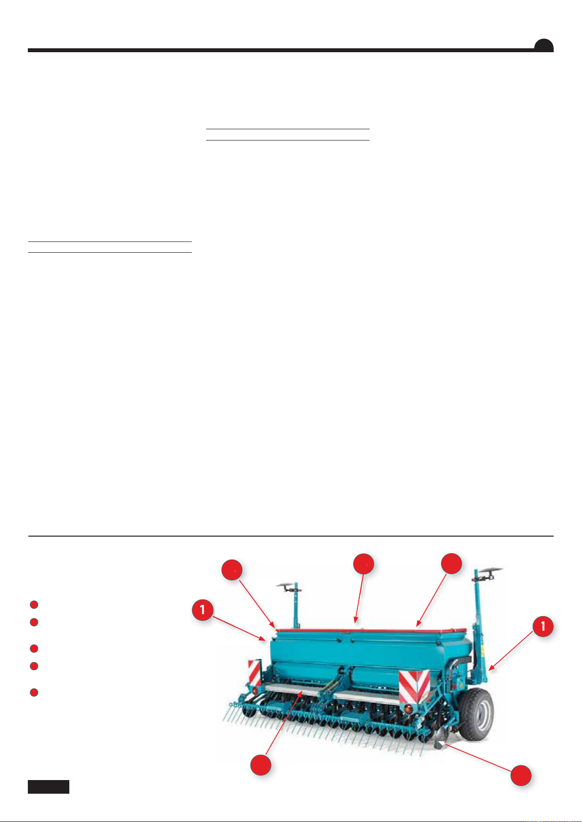
DANGER
1
Zone de fonctionnement des
traceurs
2
Risque d’écrasement attelage
triangle
3
Ne pas stationner sur la passerelle
4
Arbre en rotation
Agitateur dans la trémie
5
Pièces en mouvement :
Disque de marquage
44
Page 7

Safety regulations
2000 kg
Caution
Payload should
not be exceeded
Danger
Moving parts,
keep away
Risk of damage
to the machine
Ⴠ These symbols are used in these instructions every time recommendations are provided concerning your safety, the safety of others or the correct
operation of the machine.
ჀThese recommendations must be given to all users of the machine.
Risk of accident Operating tip
Risk of damage
to the machine
Consult the
instruction leaet
GB
GENERAL SAFETY REGULATIONS
Every time the tractor/machine assembly is to be
started up and used, you should ensure beforehand
that it complies with current legislation on safety at
work and Road Trac regulations.
GENERAL
1 - In addition to the instructions contained in this
manual, legislation relating to safety instructions
and accident prevention should be complied with.
2 - Warnings axed to the machine give indications
regarding safety measures to be observed and help
to avoid accidents.
3 - When travelling on public roads, abide by the
provisions of the Highway Code.
4 - Before starting work, it is essential that the user
familiarizes himself with the control and operating
elements of the machine and their respective
functions. When the machine is running, it may be
too late.
5 - The user should avoid wearing loose clothing
which may be caught up in the moving parts.
6 - We recommend using a tractor with a safety cab
or roll bar conforming to standards in force.
7 - Before starting up the machine and beginning
work, check the immediate surroundings,
particularly for children. Make sure that visibility is
adequate. Clear any persons or animals out of the
danger zone.
8 - It is strictly forbidden to transport any persons
or animals on board the machine whether it is in
operation or not.
9 - The machine should only be coupled up to the
tractor at the specially provided towing points and in
accordance with applicable safety standards.
10 - Extreme care must be taken when coupling or
uncoupling the machine from the tractor.
11 - Before hitching up the machine, ensure that
the front axle of the tractor is suciently weighted.
Ballast weights should be tted to the special
supports in accordance with the instructions of the
tractor manufacturer.
12 - Do not exceed the maximum axle weight or the
gross vehicle weight rating.
13 - Do not exceed the maximum authorized
dimensions for using public roads.
14 - Before entering a public road, ensure that the
protective and signalling devices (lights, reectors,
etc.) required by law are tted and working properly.
Replace burnt out bulbs with the same types and
colours.
15 - All remote controls (cords, cables, rods, hoses,
etc.) must be positioned so that they cannot
accidentally set o any manoeuvre which may cause
an accident or damage.
16 - Before entering a public road, place the machine
in the transport position, in accordance with the
manufacturer’s instructions.
17 - Never leave the driver’s position whilst the
tractor is running.
18 - The speed and the method of operation must
always be adapted to the land, roads and paths.
Avoid sudden changes of direction under all
circumstances.
19 - Precision of the steering, tractor adhesion, road
holding and eectiveness of the braking mechanism
are inuenced by factors such as the weight and
nature of the machine being towed, the front axle
stage and the state of the land or path. It is essential,
therefore, that the appropriate care is taken for each
situation.
20 - Take extra care when cornering, taking account
of the overhang, length, height and weight of the
machine or trailer being towed.
21 - Before using the machine, ensure that
all protective devices are tted and in good
condition. Damaged protectors should be replaced
immediately.
22 - Before using the machine, check that nuts and
screws are tight, particularly those for attaching
tools (discs, ickers, deectors, etc.). Tighten if
necessary.
23 - Do not stand in the operating area of the
machine.
24 - Caution! Be aware of any crushing and shearing
zones on remote-controlled and particularly
hydraulically-controlled parts.
25 - Before climbing down from the tractor, or before
any operation on the machine, turn o the engine,
remove the key from the ignition and wait until all
moving parts have come to a standstill.
26 - Do not stand between the tractor and the
machine until the handbrake has been applied and/
or the wheels have been wedged.
27 - Before any operation on the machine, ensure
that it cannot be started up accidentally.
28 - Do not use the lifting ring to lift the machine
when it is loaded.
PROPER USE OF THE MACHINE
The Seed drill must only be used for tasks for which it
has been designed.
The manufacturer will not be liable for any damage
caused by using the machine for applications other
than those specied by the manufacturer.
Using the machine for purposes other than those
originally intended will be done so entirely at the
user’s risk.
Proper use of the machine also implies:
- complying with instructions on use, care and
maintenance provided by the manufacturer;
- using only original or manufacturer recommended
spare parts, equipment and accessories.
The Seed drill must only be operated, maintained
and repaired by competent persons, familiar with
the specications and methods of operation of the
machine. These persons must also be informed of
the dangers to which they may be exposed.
The user must strictly abide by current legislation
regarding:
- accident prevention;
- safety at work (Health and Safety Regulations);
- transport on public roads (Road Trac
Regulations).
Strict compliance with warnings axed to the
machine is obligatory.
The owner of the equipment shall become liable for
any damage resulting from alterations made to the
machine by the user or any other person, without the
prior written consent of the manufacturer.
HITCHING
1 - When hitching or unhitching the machine from
the tractor, place the control lever of the hydraulic lift
in such a position that the lifting mechanism cannot
be activated accidentally.
2 - When hitching the machine to the three-point
lifting mechanism of the tractor, ensure that the
diameters of the pins or gudgeons correspond to the
diameter of the tractor ball joints.
3 - Caution! In the three-point lifting zone, there may
be a danger of crushing and shearing.
4 - Do not stand between the tractor and the
machine whilst operating the external lift control
lever.
5 - When in transport, lifting mechanism stabilizer
bars must be tted to the machine to avoid oating
and side movement.
6 - When transporting the machine in the raised
position, lock the lift control lever.
7 - Never unhitch the machine when the hopper is
lled.
DRIVE EQUIPMENT
(Power take-o and universal drive shafts)
1 - Only use universal drive shafts supplied with the
machine or recommended by the manufacturer.
2 - Power take-o and universal drive shaft guards
must always be tted and in good condition.
3 - Ensure that the tubes of the universal drive shafts
are properly guarded, both in the working position
and in the transport position.
4 - Before connecting or disconnecting a universal
drive shaft, disengage the power take-o, turn o
the engine and re-move the key from the ignition.
5 - If the primary universal drive shaft is tted with
a torque limiter or a free wheel, these must be
mounted on the machine power take-o.
6 - Always ensure that universal drive shafts are
tted and locked correctly.
7 - Always ensure that universal drive shaft guards
are immobilized in rotation using the specially
provided chains.
8 - Before engaging power take-o, ensure that
the speed selected and the direction of rotation of
5
5
Page 8
GB
3
5
4
4
2
the power take-o comply with the manufacturer’s
instructions.
9 - Before engaging power take-o , ensure that no
persons or animals are close to the machine.
10 - Disengage power take-o when the
universal drive shaft angle limits laid down by the
manufacturer are in danger of being exceeded.
11 - Caution! When power take-o has been
disengaged, moving parts may continue to rotate
for a few moments. Do not approach until they have
reached a complete standstill.
12 - On removal from the machine, rest the universal
drive shafts on the specially provided supports.
13 - After disconnecting the universal drive shafts
from the power take-o , the protective cap should be
tted to the power take-o .
14 - Damaged power take-o and universal drive
shaft guards must be replaced immediately.
HYDRAULIC CIRCUIT
1 - Caution! The hydraulic circuit is pressurized.
2 - When tting hydraulic motors or cylinders,
ensure that the circuits are connected correctly in
accordance with the manufacturer’s guidelines.
3 - Before tting a hose to the tractor’s hydraulic
circuit, ensure that the tractor-side and machine-side
circuits are not pressurized.
4 - The user of the machine is strongly recommended
to identify the hydraulic couplings between the
tractor and the machine in order to avoid wrong
connection. Caution! There is a danger of reversing
the functions (for example: raise/lower).
5 - Check hydraulic hoses once a year:
. Damage to the outer surface
. Porosity of the outer surface
. Deformation with and without pressure
. State of the ttings and seals
The maximum working life for hoses is 6 years.
When replacing them, ensure that only hoses with
the speci cations and grade recommended by the
machine manufacturer are used.
6 - When a leak is found, all necessary precautions
should be taken to avoid accidents.
7 - Pressurized liquid, particularly hydraulic circuit
oil, may cause serious injury if it comes into contact
with the skin. If the case of injury, consult a doctor
immediately. There is a risk of infection.
8 - Before any operation on the hydraulic circuit,
lower the machine, release the pressure from the
circuit, turn o the engine and remove the key from
the ignition.
MAINTENANCE
1 - Before commencing any maintenance, servicing
or repair work, or before attempting to locate the
source of a breakdown or fault, it is essential that the
power take-o is disengaged, the engine turned o
and the key removed from the ignition.
2 - Check regularly that nuts and screws are not
loose. Tighten if necessary.
3 - Before carrying out maintenance work on a
raised machine, prop it up using appropriate means
of support.
4 - When replacing a working part (fertilizer spreader
blade or seed drill coulter), wear protective gloves
and only use appropriate tools.
5 - To protect the environment, it is forbidden to
throw away oil, grease or lters of any kind. Give
them to specialist recycling rms.
6 - Before operating on the electric circuit, disconnect
the power source.
7 - Protective devices likely to be exposed to wear
and tear should be checked regularly. Replace them
immediately if they are damaged.
8 - Spare parts should comply with the standards
and speci cations laid down by the manufacturer.
Only use the manufacturer’s spare parts.
9 - Before commencing any electric welding work
on the tractor or the towed machine, disconnect the
alternator and battery cables.
10 - Repairs a ecting parts under stress or pressure
(springs, pressure accumulators, etc.) should be
carried out by suitably quali ed engineers with
special tools.
DANGER
1
Marker working area
2
Danger of crushing by triangular
hitch
3
Do not ride on the platform
4
Rotating shaft
Seed box agitator
5
Moving parts:
Marker disc
66
Page 9

Sicherheitsvorschriften
2000 kg
Achtung
Nutzlast niemals
überschreiten
Gefahr Bewegliche
Maschinenteile - sich
erst bei Stillstand
nähern
Gefahr der
Beschädigung
der Maschine
ჀI n der Anweisung werden diese Zeichen in Verbindung mit Empfehlungen für Ihre Sicherheit und der anderer sowie die gute Funktion der Maschine
verwendet.
ჀJeder Benutzer dieser Maschine muß diese Vorschriften genau kennen..
Verletzungsgefahr Hinweis zur
Erleichterung der
Arbeit
Beschädigungsgefahr
Siehe Betriebsanleitung
der Maschine
DE
ALLGEMEINE SICHERHEITSVORSCHRIFTEN
Vor jeder Benutzung und Inbetriebsetzung der
Schlepper-Maschine-Einheit kontrollieren, ob sie
den Sicherheitsvorschriften und den Vorschriften der
Straßenverkehrsordnung entsprechen.
ALLGEMEINES
1 - Zusätzlich zu den in diesem
Handbuch enthaltenen Anweisungen die
Gesetzgebung bezüglich der Sicherheits- und
Unfallverhütungvorschriften einhalten.
2 - Die auf der Maschine angebrachten
Warnungen informieren über die einzuhaltenden
Sicherheitsmaßnahmen und tragen zur
Unfallverhütung bei.
3 - Im Straßenverkehr die Straßenverkehrsordnung
einhalten.
4 - Vor Arbeitsbeginn muß sich der
Benutzer unbedingt mit den Antriebs- und
Bedienungsorganen der Maschine und ihren
jeweiligen Funktionen vertraut machen. Während
der Arbeit ist es dafür zu spät.
5 - Weite Kleidungsstücke, die in sich bewegende
Teile geraten könnten, vermeiden.
6 - Es empehlt sich, gemäß den gültigen
Normen einen Schlepper mit Kabine oder
Sicherheitsverstärkung zu verwenden.
7 - Vor Inbetriebsetzung und Arbeitsbeginn die
direkte Umgebung kontrollieren (Kind!). Für
ausreichende Sicht sorgen! Personen oder Tiere
aus dem Maschinengefahrenbereich entfernen
(Schutzvorrichtungen!).
8 - Der Transport von Personen oder Tieren auf der
Maschine ist während der Arbeit oder beim Fahren
streng verboten.
9 - Die Maschine darf gemäß den geltenden
Sicherheitsnormen nur an den dafür vorgesehenen
Kupplungspunkten angehängt werden.
10 - Besondere Vorsicht ist beim An- und Abbau der
Maschine am Schlepper geboten.
11 - Vor Anhängen der Maschine kontrollieren,
ob der Ballast des Schleppers genügt. Die
Ballastelemente müssen gemäß den Vorschriften
des Schlepperherstellers auf den dafür vorgesehenen
Haltern angebracht werden.
12 - Die maximale Achslast und das zulässige
Gesamtgewicht einhalten.
13 - Das für den Straßenverkehr maximal zulässige
Außenmaß einhalten.
14 - Vor Straßenbenutzung die Schutzvorrichtungen
und Signalisierungsvorrichtungen (Licht- und
Rückstrahlelemente) anbringen und ihre Funktion
prüfen. Die defekten Glühbirnen durch Modelle
identischer Art und Farbe ersetzen.
15 - Alle Fernsteuerungen (Seil, Kabel, Stange,
Schlauch) müssen so positioniert sein, daß sie nicht
ungewollt betätigt werden und dadurch Unfälle oder
Schäden hervorrufen können.
16 - Vor Benutzung der Straße die Maschine gemäß
Herstelleranweisungen in Transportstellung bringen.
17 - Fahrersitz nie bei laufender Maschine verlassen.
18 - Fahrgeschwindigkeit und -weise müssen immer
dem Gelände, den Straßen und Wegen angepaßt
sein. Auf alle Fälle plötzliche Richtungsänderungen
vermeiden.
19 - Die Präzision der Lenkung, die Bodenhaftung
des Schleppers, die Straßenlage und die Wirksamkeit
der Bremsvorrichtungen werden beeinußt von
Faktoren wie: Gewicht und Art der angebauten
Maschine, Belastung der Vorderachse, Zustand des
Geländes oder der Fahrbahn. Die den Bedingungen
entsprechenden Vorsichtsmaßnahmen einhalten.
20 - Besondere Vorsicht ist in Kurven geboten.
Schwerpunktlage, Länge, Höhe und Gewicht der
Maschine oder des Anhängers berücksichtigen.
21 - Vor jeder Benutzung der Maschine kontrollieren,
ob alle Schutzvorrichtungen angebracht und in
gutem Zustand sind. Bei Beschädigung sofort
austauschen.
22 - Vor jeder Benutzung kontrollieren, ob alle
Schrauben und Muttern fest angezogen sind,
insbesondere die, mit denen die Geräte befestigt sind
(Scheiben, Paletten, Schirme...). Notfalls anziehen.
23 - Sich nicht im Manövrierbereich der Maschine
aufhalten.
24 - Vorsicht! Auf den Fernsteuerungsorganen,
insbesondere auf denen mit hydraulischem
Regelkreis, kann es Stauch- und Abscherzonen
geben.
25 - Vor Verlassen des Schleppers oder vor jedem
Eingri auf der Maschine Motor abschalten,
Zündschlüssel abziehen und völligen Stillstand aller
bewegten Teile abwarten.
26 - Sich nicht zwischen Schlepper und Maschine
aufhalten, ohne zuvor die Parkbremse angezogen
und/oder Keile unter die Räder gelegt zu haben.
27 - Vor jedem Eingri an der Maschine
kontrollieren, ob diese nicht ungewollt in Betrieb
gesetzt werden kann.
28 - Die Aufhängöse nicht zum Heben der gefüllten
Maschine benutzen.
BESTIMMUNGSGEMÄSSE VERWENDUNG DER
MASCHINE
Die Drillmaschine darf nur für die Arbeiten eingesetzt
werden, für die er geplant ist.
Bei Beschädigung der Maschine infolge einer nicht
vom Hersteller spezizierten Benutzung ist dieser
nicht haftbar.
Jede nicht der ursprünglichen Bestimmung der
Maschine entsprechende Benutzung erfolgt auf
Rechnung und Gefahr des Benutzers.
Die bestimmungsgemäße Verwendung der
Maschine setzt ebenfalls voraus:
- die Einhaltung der vom Hersteller
verordneten Benutzungs-, Wartungs- und
Instandsetzungsvorschriften,
- die ausschließliche Verwendung von
Originalersatzteilen, Originalausrüstungen und
Originalzubehör oder von Teilen, die vom Hersteller
empfohlen sind.
Die Drillmaschine darf nur von kompetenten,
mit den technischen Daten und
Benutzungsanweisungen der Maschine vertrauten
Personen benutzt, gewartet und repariert werden,
die über die Risiken informiert sind, denen sie
ausgesetzt sein könnten.
Streng die gültige Reglementierung einhalten
bezüglich:
- der Unfallverhütung,
- der Arbeitssicherheit (Arbeitsgesetzbuch)
- des Straßenverkehrs (Straßenverkehrsordnung).
Die auf der Maschine angebrachten Warnungen
berücksichtigen.
Der Hersteller haftet nicht für Schäden, die durch
Abänderungen entstehen, die vom Benutzer selbst
oder von Dritten ohne schriftliche Genehmigung an
der Maschine vorgenommen wurden.
ANHÄNGUNG
1 - Beim An- und Abkuppeln der Maschine am
Schlepper, den Steuerhebel des Hydraulikkrafthebers
so stellen, daß der Hub-vorgang nicht unerwartet
ausgelöst werden kann.
2 - Beim Anhängen der Maschine am
Dreipunktkraftheber des Schleppers darauf
achten, daß die Spindel- oder Zapfendurchmesser
dem Durchmesser der Schlepperkugelgelenke
entsprechen.
3 - Vorsicht! Im Dreipunkt-Hubbereich bestehen
Stauch- und Abscherrisiken!
4 - Sich bei Betätigung des äußeren KraftheberSteuerhebels nicht zwischen Schlepper und
Maschine aufhalten.
5 - Beim Transport muß die Maschine durch die
Versteifungsstreben des Krafthebers zur Vermeidung
von Unwucht und seitlicher Pendelung stabilisiert
werden.
6 - Beim Transport der Maschine in angehobener
Stellung den Kraftheber-Steuerhebel blockieren.
7 - Maschine niemals bei gefülltem Tank abkuppeln.
ANTRIEBSORGANE
(Zapfwelle und Gelenkwellen-Antrieb)
1 - Nur die mit der Maschine gelieferte oder vom
Konstrukteur empfohlene Gelenkwelle verwenden.
2 - Die Schutzvorrichtungen der Zapfwellen und
Gelenkwellen müssen immer angebracht und in
gutem Zustand sein.
3 - Auf die richtige Überlappung der
Gelenkwellenrohre sowohl in Arbeits- als auch in
Transportstellung achten.
4 - Vor Anschließen oder Abziehen einer Gelenkwelle
die Zapfwelle auskuppeln, den Motor abschalten
und den Zündschlüssel abziehen.
7
Page 10

DE
3
5
4
4
2
5 - Ist die Primärkardanwelle mit einem
Drehmomentbegrenzer oder einer Freilaufkupplung
ausgestattet, müssen diese unbedingt auf der
Zapfwelle der Maschine montiert sein.
6 - Immer auf die korrekte Montage und
Verriegelung der Kardanantriebe achten.
7 - Immer darauf achten, daß die
Schutzvorrichtungen der Gelenkwellen mit den dafür
vorgesehenen Ketten gegen Verdrehen gesichert
sind.
8 - Vor Kuppeln der Zapfwelle prüfen, ob die
gewählte Drehzahl und die Drehrichtung der
Zapfwelle den Vorschriften des Herstellers
entsprechen.
9 - Vor Kuppeln der Zapfwelle kontrollieren, ob sich
keine Personen oder Tiere in Nähe der Maschine
be nden.
10 - Die Zapfwelle auskuppeln, wenn Gefahr besteht,
daß die vom Hersteller vorgeschriebenen Grenzen
des Gelenkwellenwinkels überschritten werden.
11 - Vorsicht! Nach Auskuppeln der Zapfwelle
können Teile der Maschine noch einige Zeit
nachlaufen. Sich ihnen nie vor völligem Stillstand
nähern.
12 - Bei Abbau der Maschine die Gelenkwellen auf
den dafür vorgesehenen Haltern ablegen.
13 - Nach Abziehen der Gelenkwelle von der
Schlepperzapfwelle muß diese mit ihrer Schutzkappe
bedeckt werden.
14 - Schadhafte Schutzvorrichtungen der Zapfwelle
und der Gelenkwellemüssen sofort ausgewechselt
werden.
HYDRAULIKLEITUNG
1 - Vorsicht! Die Hydraulikleitung steht unter Druck.
2 - Bei Montage von Zylindern oder
Hydraulikmotoren auf den korrekten Anschluß
gemäß Anweisungen des Herstellers achten.
3 - Vor Anschluß eines Schlauches an der
Hydraulikleitung des Schleppers dafür sorgen, daß
die schlepper- und maschinenseitigen Leitungen
nicht unter Druck stehen.
4 - Dem Benutzer der Maschine wird zur Vermeidung
falscher Anschlüsse dringend geraten, die
Kennzeichnungen auf den Hydraulikanschlüssen
zwischen Schlepper und Maschine zu beachten, da
sonst die Gefahr einer Funktionsumkehrung besteht.
(z.B.: Heben/Senken).
5 - Einmal im Jahr die Hydraulikschläuche
kontrollieren auf:
. Beschädigung der Außenschicht
. Porosität der Außenschicht
. Verformung ohne Druck und unter Druck
. Zustand der Verbindungen und Dichtungen.
Die maximale Benutzungsdauer der Schläuche
ist 6 Jahre. Beim Auswechseln darauf achten,
daß nur Schläuche verwendet werden, deren
Eigenschaften und Qualität den Vorschriften des
Maschinenkonstrukteurs entsprechen.
6 - Bei Feststellung einer undichten Stelle alle
Vorsichtsmaßnahmen zur Unfallverhütung tre en.
7 - Eine unter Druck stehende Flüssigkeit,
insbesondere das Öl der Hydraulikleitung, kann
die Haut durchdringen und schwere Verletzungen
verursachen! Bei Verletzungen sofort Arzt
Konsultieren; Infektionsgefahr!
8 - Vor jedem Eingri in die Hydraulikanlage
Maschine ablassen, Anlage drucklos schalten, Motor
abstellen und Zündschlüssel abziehen.
WARTUNG
1 - Vor Instandsetzungs-, Wartungs- oder
Reparaturarbeiten sowie bei Ermitteln einer Pannenoder Betriebsstörungsquelle muß die Zapfwelle
ausgekuppelt, der Motor abgeschaltet und der
Zündschlüssel abgezogen sein.
2 - Regelmäßig kontrollieren, ob Schrauben und
Muttern fest angezogen sind. Notfalls anziehen.
3 - Vor Wartung einer Maschine in angehobener
Stellung diese mit einem geeigneten Mittel
abstützen.
4 - Beim Austausch eines Funktionsteiles (Schaufel
bei Streuern oder Schare bei Drillmaschinen)
Schutzhandschuhe tragen und nur geeignete Werkzeuge
benutzen.
5 - Zum Schutz der Umwelt ist es verboten, Öl, Fett
und Filter jeder Art wegzuwerfen oder auszugießen.
Sie sind von darauf spezialisierten Unternehmen zu
entsorgen.
6 - Vor Eingri an der elektrischen Leitung die
Stromzufuhr unterbrechen.
7 - Verschleiß ausgesetzte Schutzvorrichtungen
müssen regelmäßig kontrolliert werden. Sie sofort
austauschen, wenn schadhaft.
8 - Ersatzteile müssen den vom Konstrukteur
festgelegten Normen und Kennwerten entsprechen.
Nur Ersatzteile des Herstellers verwenden!
9 - Vor Elektroschweißarbeiten am Schlepper
oder der angehängten Maschine die Kabel des
Wechselstromgenerators und der Batterie abziehen.
10 - Reparaturen an Organen, die unter Spannung
oder Druck stehen (Federn, Druckspeicher, usw...)
setzen eine ausreichende Quali kation voraus und
erfordern Werkzeuge; sie dürfen daher nur von
quali ziertem Personal durchgeführt werden.
GEFAHR
1
Arbeitsbereich der Spurreißer
2
Stauchgefahr Kupplungsdreieck
3
Aufenthalt auf dem Ladesteg nicht
gestattet
4
Rotierende Welle
Rührwerk im Kasten
5
Umlaufende Teile:
Markierscheibe
88
Page 11

Français SOMMAIRE
Pages
13
12-13
13
14-15
20-21
20-21
Pages
30-39
40-47
48-49
50-51
Pages
65
64-65
66-67
68-69
70-71
MISE EN ROUTE
• A
Préparation de la machine
• B
Manutention
• C
Manœuvrer en bout de champ
• D
Contrôle tracteur
• E
Attelage
• F
Aplomb
REGLAGES
• A
Réglage du débit
• B
Traceurs
• C
Réglage du terrage
• D
Réglage de la herse de
recouvrement
ENTRETIEN
• A
Nettoyage
• B
Graissage
• C
Distribution
• D
Caractéristiques techniques
• E
Positions Autocollants
22-23
24-25
24-25
26-27
28-29
52-61
62-63
62-63
• G
Béquille
• H
Branchement hydraulique
• I
Branchement Electrique/
électronique
• J
Passerelle de chargement
• K
Remplissage de la trémie
• E
Dispositif de marquage
• F
Débrayage demi-semoir
• G
Vidange de la trémie
1
2
3
Pages
72-73
72-73
74-75
74-75
76-77
78-79
Pages
86
87-115
EQUIPEMENTS
• A
Limiteur de profondeur pour
soc traînant
• B
Uniband pour soc traînant
• C
Compteur d’hectares
• D
Electronique
• E
Modulation de débit MS
• F
Réhausse
TABLEAUX DE REGLAGE
• A
Rappel pré-réglages
• B
Tableaux de débit
Lire attentivement la notice avant l’utilisation. Comprendre son semoir
c’est mieux l’utiliser. En français suivre le symbole.
78-79
78-79
80-81
82-83
84-85
84-85
• G
Agitateur souple
• H
Chapes d’attelage oscillantes
• I
Modulation de terrage
• J
Roues de réappui
• K
Eaces traces de roue de
tracteur
• L
Eace trace de roue de semoir
FR
4
5
99
9
Page 12

English CONTENTS
STARTUPPages
13
12-13
13
16-17
20-21
20-21
• A
Preparing the machine
• B
Handling
• C
End-of-eld manoeuvres
• D
Tractor control
• E
Hitching
• F
Vertical setting
22-23
24-25
24-25
26-27
28-29
• G
Parking stand
• H
Hydraulics connection
• I
Electrics/Electronics
connection
• J
Loading platform
• K
Filling the seed box
Pages
30-39
40-47
48-49
50-51
Pages
65
64-65
66-67
68-69
70-71
Pages
72-73
72-73
74-75
74-75
76-77
78-79
SETTINGS
• A
Setting the ow
• B
Markers
• C
Setting the depth control
• D
Adjusting the covering harrow
MAINTENANCE
• A
Cleaning
• B
Lubrication
• C
Distribution
• D
Technical specications
• E
Sticker positions
ACCESSORIES
• A
Depth limiter for Suolk
coulter
• B
Uniband for Suolk coulter
• C
Areameter
• D
Electronics
• E
Flow modulation MS
• F
Seed box extension
52-61
62-63
62-63
78-79
78-79
80-81
82-83
84-85
84-85
• E
Tramlining
• F
Disengaging half of the seed
drill
• G
Emptying the seed box
• G
Rubber agitator
• H
Floating linkage cover
• I
Adjusting the depth control
• J
Packer wheels
• K
Tractor wheel track eradicators
• L
Seed drill wheel track
eradicator
10
Pages
86
87-115
SETTING CHARTS
• A
Pre-setting reminder
• B
Seeding rate charts
Read the manual carefully before use. Better understanding
means better and safer sowing. For English follow the symbol.
GB
Page 13
Deutsch VERZEICHNIS
INBETRIEBSETZUNGSeite
13
12-13
13
18-19
20-21
20-21
• A
Vorbereitung der Maschine
• B
Handhabung
• C
Manövrieren am Feldende
• D
Schleppersteuerung
• E
Anbau
• F
Senkrechtstellung
22-23
24-25
24-25
26-27
28-29
• G
Abstellstütze
• H
Hydraulikanschluß
• I
Elektrischer/Elektronischer
Anschluß
• J
Ladesteg
• K
Füllen des Saatkastens
1
Seite
30-39
40-47
48-49
50-51
Seite
65
64-65
66-67
68-69
70-71
Seite
72-73
72-73
74-75
74-75
76-77
78-79
EINSTELLUNGEN
• A
Einstellung der Saatmenge
• B
Spurreißer
• C
Schardruckeinstellung
• D
Einstellung des Saatstriegels
WARTUNG
• A
Reinigung
• B
Schmierung
• C
Verteilung
• D
Technische Daten
• E
Sicherheitsaufkleber
AUSRÜSTUNGEN
• A
Sätiefenbegrenzer Für
Schleppschar
• B
Uniband Für Schleppschar
• C
Hektarzähler
• D
Elektronik
• E
Saatmengenverstellung MS
• F
Aufsatz
52-61
62-63
62-63
78-79
78-79
80-81
82-83
84-85
84-85
• E
Fahrgassenanlage
• F
Abschalten 1/2 Drillmaschine
• G
Entleeren des Saatkastens
• G
Elastische Rührwelle
• H
Schwingkupplungsvorrichtung
• I
Andruckrollen
• J
Saatandrückräder
• K
Löscht die Spuren der Schlepperräder
• L
Löscht die Spuren der
Drillmaschinenräder
2
3
4
Seite
86
87-115
EINSTELLTABELLEN
• A
Zur Erinnerung:
Voreinstellungen
• B
Sämengentabellen
Anweisung vor Benutzung sorgfältig durchlesen. Die Drillmaschine
verstehen, heißt sie besser benutzen. Die deutsche Fassung ist mit
gekennzeichnet.
DE
5
1111
Page 14
Mise en route / Start-up / Inbetriebsetzung
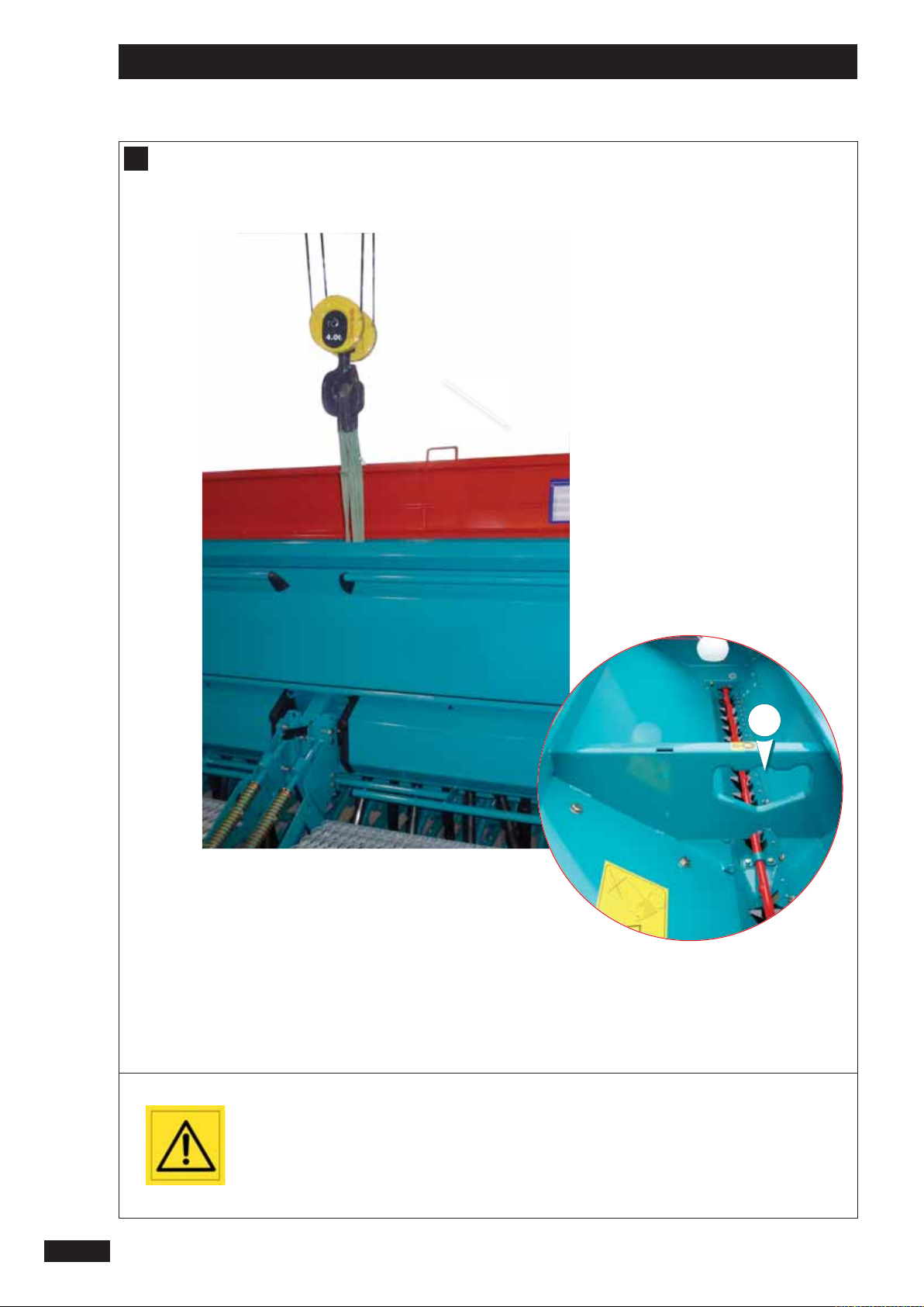
B
Ne lever le semoir qu’avec la
trémie vide.
Assurez-vous qu’il n’y
ait personne autour de
la machine lors de la
manipulation.
Do not lift the seed drill
unless the hopper is empty.
Ensure that all personnel
are a safe distance
from the machine when
manoeuvring.
1
Die Sämaschine darf nur
mit leeren Saatgutbehälter
angehoben werden.
Vergewissern Sie sich, dass
sich bei Betätigung der
Maschine niemand in der
unmittelbaren Nähe der
Maschine aufhält.
1212
Page 15
Mise en route / Start-up / Inbetriebsetzung
A
Préparation de la machine
B
Manutention
FR
Au moment de la livraison, véri er que le semoir est complet.
- Assurez-vous qu’il n’y ait pas de corps étrangers dans la
trémie.
Le semoir ne doit être utilisé que pour les travaux pour
lesquels il a été conçu.
-Véri er que la machine n’a subi aucun dommage en
cours de transport et qu’il ne manque aucune pièce.
Seules les réclamations formulées à réception de la machine
pourront être prises en considération.
- Faire constater d’éventuels dégâts par le transporteur.
- En cas de doute ou de litige, adressez-vous à votre
revendeur.
A
Preparing the machine
On delivery, check that the seed drill is complete.
- Ensure that there are no foreign bodies in the seed box.
The seed drill must only be used for the purposes for which it
was designed.
- Check that the machine has not su ered any damage
during transport and that no parts are missing.
Only claims made on taking delivery of the machine will be
considered.
- Utiliser l’emplacement 1 prévu à cet e et.
Manœuvrer en bout de champ
C
Le semoir donne une plus grande liberté de manœuvre avec
un gain de temps appréciable.
Toutefois, nous conseillons la démarche suivante :
- Relever le traceur
- Réduire le régime moteur
- Relever la machine
(possibilité de débrayer la prise de force)
- Faire demi-tour
- Descendre la machine
(remettre en marche progressivement)
- Baisser le traceur
B
Handling
- Use the space 1 provided for this purpose.
End-of- eld manoeuvres
C
The seed drill gives greater freedom of movement which
results in appreciable time savings.
However, we recommend the following procedure:
- Lift the marker
- Reduce the engine speed
1
GB
- Any damage should be reported to the delivery man.
- If in doubt or in the event of any complaint, please
contact your dealer.
Vorbereitung der Maschine
A
Bei Lieferung prüfen, ob die Drillmaschine komplett ist.
- Prüfen, ob sich kein Fremdkörper im Saatkasten be ndet.
Die Sämaschine darf nur für die vorbestimmten Arbeiten
verwendet werden.
- Prüfen, ob die Maschine beim Transport nicht
beschädigt worden ist und kein Teil fehlt.
Nur bei Abnahme der Maschine formulierte Reklamationen
können berücksichtigt werden.
- Eventuelle Schäden vom Spediteur feststellen lassen.
- Im Zweifels- oder Streitfall Ihren Verkäufer informieren
- Lift the machine
(possibility of disengaging the PTO)
- Turn the tractor around
- Lower the machine
(start up again gradually)
- Lower the marker.
Handhabung
B
- Die zu diesem Zweck vorgesehene Stelle 1 verwenden.
Manövrieren am Feldende
C
Die Drillmaschine erlaubt größere Bewegungsfreiheit mit
beträchtlicher Zeitersparnis. Wir empfehlen jedoch folgendes Vorgehen:
- Spurreißer anheben
- Motordrehzahl reduzieren
- Maschine anheben
(Zapfwelle kann ausgekuppelt werden)
- Wenden
- Maschine senken
(stufenweise wiedereinschalten)
DE
- Spurreißer senken
1313
Page 16
Mise en route
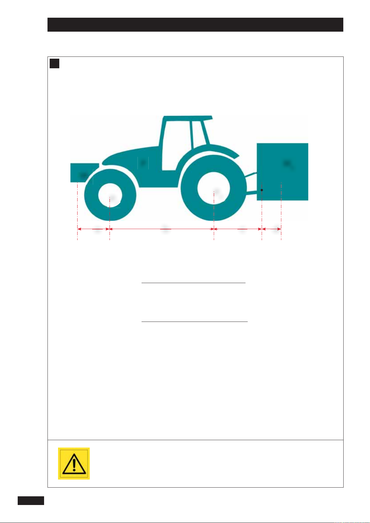
D
M
1
P
1
ᇗM1mini =
ᇗP1c =
P M
P
2
b c da
M2 x (c + d) - P1 x b + (0,2 x P x b)
a + b
M1 x (a + b) + P1 x b - M2 x (c + d)
b
=..........................Kg
=..........................Kg
2
14
ᇗPc = M1 + P + M2 =..........................Kg
ᇗP2c = Pc - P1c =..........................Kg
La charge sur l’essieu avant
du tracteur doit être égal au
moins à 20% du poids à vide
du tracteur.
Page 17
Mise en route
D
Contrôle tracteur
- A vérier :
• Le poids total autorisé.
• Les charges par essieu autorisées.
• La charge d’appui autorisée au point d’accouplement du tracteur.
• Les capacités de charge admissibles des pneumatiques montés sur le tracteur.
• La charge d’attelage autorisée est-elle susante ?
FR
Toutes ces indications sont sur la carte grise, ou sur la plaque signalétique et dans la notice tracteur.
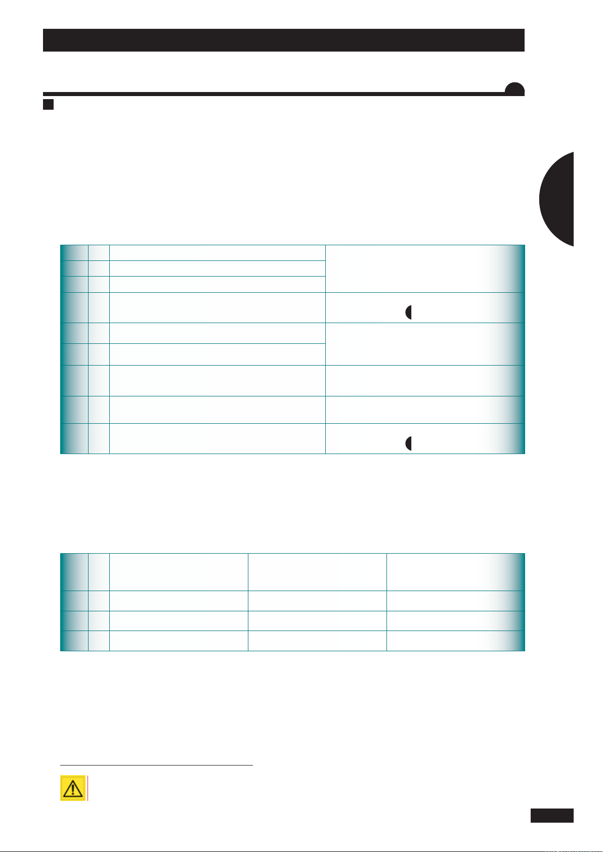
VALEURS À CONNAÎTRE
PKgPoids à vide du tracteur
P1 Kg Charge sur l’essieu avant du tracteur vide
P2 Kg Charge sur l’essieu arrière du tracteur vide
M2 Kg Poids total machine à l’arrière
M1 Kg Poids total du lest à l’avant
am
bmEmpattement du tracteur
cm
dm
ᇗ M1 mini = Calcul du lestage nécessaire à l’avant au minimum. ᇗ P1c = Calcul de la charge sur l’essieu avant
ᇗ Pc = Calcul du poids total de l’ensemble (tracteur +machine) ᇗ P2c = Calcul de la charge sur l’essieu arrière
Distance entre le centre de gravité du lest avant et le
centre de l’essieu avant
Distance entre l’axe attelage inférieur et le centre de
l’essieu arrière
Distance entre l’axe attelage inférieur et le centre de gravité de la machine
Consulter la notice d’utilisation ou la carte grise du
tracteur.
Consulter les caractéristiques techniques de la machine. (Voir chapitre
Consulter les caractéristiques techniques du tracteur
et du lest avant, ou mesurer.
Consulter la notice d’utilisation ou la carte grise du
tracteur, ou mesurer.
Consulter la notice d’utilisation ou la carte grise du
tracteur, ou mesurer.
Consulter les caractéristiques techniques de la machine. (Voir chapitre
3
« Caractéristiques »).
3
« Caractéristiques »).
1
Kg
P1c
P2c
Pc
- Complétez le tableau ci-dessus:
- Vériez que :
• Les valeurs calculées doivent être < ou = aux valeurs autorisées pour le tracteur et aussi par les pneumatiques montés sur le
tracteur.
• Il faut impérativement respecter sur l’essieu avant du tracteur une charge minimum > ou = à 20% de la charge du tracteur
à vide.
Il est interdit d’atteler la machine à un tracteur si :
ᇗLa charge totale calculée est > à la valeur autorisée
ᇗLa charge sur l’essieu avant est < au minimum requis
Valeurs calculées
tracteur
Valeurs autorisées par le
Valeurs autorisées
par les pneumatiques
montés sur le tracteur
15
Page 18

Start-up
D
M
1
P
1
ᇗM1mini =
ᇗP1c =
P M
P
2
b c da
M2 x (c + d) - P1 x b + (0,2 x P x b)
a + b
M1 x (a + b) + P1 x b - M2 x (c + d)
b
=..........................Kg
=..........................Kg
2
16
ᇗPc = M1 + P + M2 =..........................Kg
ᇗP2c = Pc - P1c =..........................Kg
The weight on the tractor’s
front axle should be at least
20% of the unladen weight
of the tractor.
Page 19
Start-up
D
Tractor control
- To be checked :
• The total authorised weight.
• The permitted weight per axle.
• The authorised support weight on the tractor’s linkage.
• The permissible load capacity for the tyres tted to the tractor.
• Is the authorised linkage weight sucient?
GB
All of this information can be found on the registration papers, or on the data plate and in the tractor manual.
FIGURES THAT YOU SHOULD KNOW-
PKgUnladen weight of tractor
P1 Kg Weight on the front axle when the tractor is empty
P2 Kg Weight on the rear axle when the tractor is empty
M2 Kg Total weight with machine attached to rear
M1 Kg Total weight of front ballast
am
bmWheelbase of tractor
cm
dm
ᇗ M1 mini = Calculation of the minimum ballast need in front. ᇗ P1c = Calculation of the weight on the front axle
ᇗ Pc = Calculation of the total weight of the unit (tractor + machine) ᇗ P2c = Calculation of the weight on the rear axle
Distance between the centre of gravity of the front ballast
and the centre of the front axle
Distance between the lower linkage pins and the centre of
the rear axle.
Distance between the lower linkage pins and the centre of
gravity of the machine.
Consult the tractor’s instruction manual or the registration documents.
Consult the machine’s technical characteristics. (see
3
section
Consult the technical characteristics of the tractor
and the front ballast, or measure.
Consult the instruction manual or the tractor’s registration documents, or measure.
Consult the instruction manual or the tractor’s registration documents, or measure.
Consult the technical characteristics of the machine.
(see section
“Characteristics”).
3
“Charactéristics”).
1
Values
calculated
P1c
P2c
Pc
- Complete the table below:
- Check that:
• The values calculated should be < or = to the tractor’s permissible values and the values for
the tyres tted to the tractor.
• It is essential that the minimum load on the front axle is > or = to 20% of the unladen tractor
weight.
THE MACHINE MUST NOT BE HITCHED TO A TRACTOR IF :
ᇗThe total weight calculated is > than the maximum authorised weight.
ᇗThe weight on the front axle is < than the minimum required.
Tractor’s
permissible values
Values permissible with
the tyres that are
tted to the tractor
17
Page 20

Inbetriebsetzung
D
M
1
P
1
ᇗM1mini =
ᇗP1c =
P M
P
2
b c da
M2 x (c + d) - P1 x b + (0,2 x P x b)
a + b
M1 x (a + b) + P1 x b - M2 x (c + d)
b
=..........................Kg
=..........................Kg
2
18
ᇗPc = M1 + P + M2 =..........................Kg
ᇗP2c = Pc - P1c =..........................Kg
Die vordere Achslast
des Schleppers muss
mindestes 20 % des
Schleppereigengewichts
betragen.
Page 21
Inbetriebsetzung
D
Schleppersteuerung
- Bitte prüfen :
• Zulässiges Gesamtgewicht.
• Zulässige Achslast.
• Zulässiger Auagedruck am Schlepperanbaupunkt.
• Zulässiges Ladegewicht der Schlepperreifen.
• Ist die zulässige Zuglast ausreichend?
DE
Sämtliche dieser Angaben sind auf dem Fahrzeugschein oder auf dem Typenschild und im Schlepperhandbuch vermerkt.
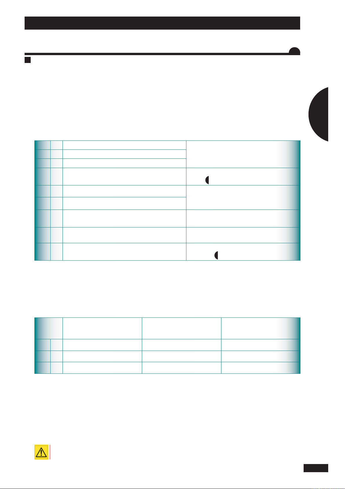
WICHTIGE WERTE
PKgSchleppereigengewicht
P1 Kg Vordere Achslast bei leerem Schlepper
P2 Kg Hintere Achslast bei leerem Schlepper
M2 Kg Gesamtgewicht Maschine hinten
M1 Kg Ballastgewicht vorne
am
bmRadabstand Schlepper
cm
dm
ᇗ M1 mini = Berechnung des erforderlichen Mindestballasts vorne. ᇗ P1c = Berechnung der Vorderachslast
ᇗ Pc = Berechnung der Gesamtlast (Schlepper +Maschine) ᇗ P2c = Berechnung der Hinterachslast
Abstand zwischen Ballastschwerpunkt vorne und Achsmittelpunkt vorne
Abstand zwischen unterer Ankupplungsachse und dem
Achsmittelpunkt hinten
Abstand zwischen unterer Ankupplungsachse und dem
Schwerpunkt der Maschine
Siehe Handbuch oder Fahrzeugschein des Schleppers.
Technische Daten der Maschine einsehen. (siehe
3
Kapitel
Technische Daten des vorne ballastierten Schleppers
einsehen oder messen.
Siehe Handbuch oder Fahrzeugschein des Schleppers oder messen.
Siehe Handbuch oder Fahrzeugschein des Schleppers oder messen.
Technische Daten der Maschine einsehen. (siehe
Kapitel
“Technische Daten”).
3
“Technische Daten”).
1
Berechnete
Wer te
P1c
P2c
Pc
- Untenstehende Tabelle ausfüllen :
- Überprüfen Sie Folgendes :
• Die berechneten Werte müssen < oder = der für den Schlepper bzw. für die Schlepperreifen zulässigen Werte sein
• Die Vorderachse muss unbedingt mit > oder = 20 % des Schleppereigengewichts ballastiert sein.
Maschine nicht an den Schlepper ankuppeln, solange :
ᇗDie berechnete Gesamtlast > als der zulässige Wert ist.
ᇗDer Ballast auf der Vorderachse < als der erforderliche Mindestballast ist.
Für den Schlepper
zulässige Werte
Für die Schlepperreifen
zulässige Werte
19
Page 22
Mise en route / Start-up / Inbetriebsetzung
E
F
2020
Respectez l’aplomb de la
machine au travail.
Dans le cas d’une utisation
avec un outil de travail
du sol, lors d’un transport
routier, attention à la
hauteur totale.
Check the vertical setting of
the machine before working.
When using a cultivating
implement, check the overall
height before any road
transport.
Senkrechtstellung der
Maschine bei der Arbeit
einhalten.
Bei Verwendung mit einem
Bodenbearbeitungsgerät
und bei Straßentransport
auf die Gesamthöhe achten
Page 23
Mise en route / Start-up / Inbetriebsetzung
E
Attelage
F
FR
Aplomb
Équipé d’un attelage oscillant en option, le semoir peut être
attelé :
- Soit directement sur le tracteur,
- Soit sur un outil de travail du sol.
En position de travail du semoir, le relevage hydraulique du
tracteur doit toujours être abaissé à fond et ottant.
Dans le cas d’une utilisation avec un outil de travail
du sol, lors d’un transport routier, attention à la
hauteur totale
E
Hitching
Fitted with an optional swinging drawbar, the seed drill may
be hitched:
- Directly to the tractor,
- Or to a cultivating implement.
When the drill is in the working position, the tractor’s hydraulic lift system should always be fully lowered and in the
oating position.
- Poser l’appareil sur un sol horizontal.
- Régler l’aplomb à l’aide du 3ème point du tracteur en
vous aidant de la èche de contrôle 1 qui est xée sur le
semoir.
F
Vertical setting
- Lay the machine on horizontal ground.
- Adjust the vertical setting using the 3rd point on the
tractor and the control arrow 1 on the seed drill.
1
GB
When using a cultivating implement, check the
overall height before any road transport.
Anbau
E
Optional mit einer vibrierenden Aufhängung ausgestattet
kann die Drillmaschine wie folgt angekoppelt werden:
- Entweder direkt an den Schlepper,
- Oder an ein Bodenbearbeitungsgerät.
Wenn die Drillmaschine in Arbeitsstellung ist, muß der Hydraulikkraftheber des Schleppers immer völlig gesenkt und
weichgelagert sein.
Bei Verwendung mit einem Bodenbearbeitungsgerät und bei Straßentransport auf die Gesamthöhe
achten.
Senkrechtstellung
F
- Gerät auf horizontalen Boden stellen.
- Senkrechtstellen mit Hilfe des 3. Ankupplungspunktes
und des Kontrollpfeils 1 an der Drillmaschine.
DE
2121
Page 24
Mise en route / Start-up / Inbetriebsetzung
3
G
2
2
2222
Ne pas oublier de retirer la
béquille avant de travailler.
Do not forget to remove
the parking support before
working.
Nicht vergessen, Stütze vor
Arbeitbeginn zu entfernen.
Page 25
Mise en route / Start-up / Inbetriebsetzung
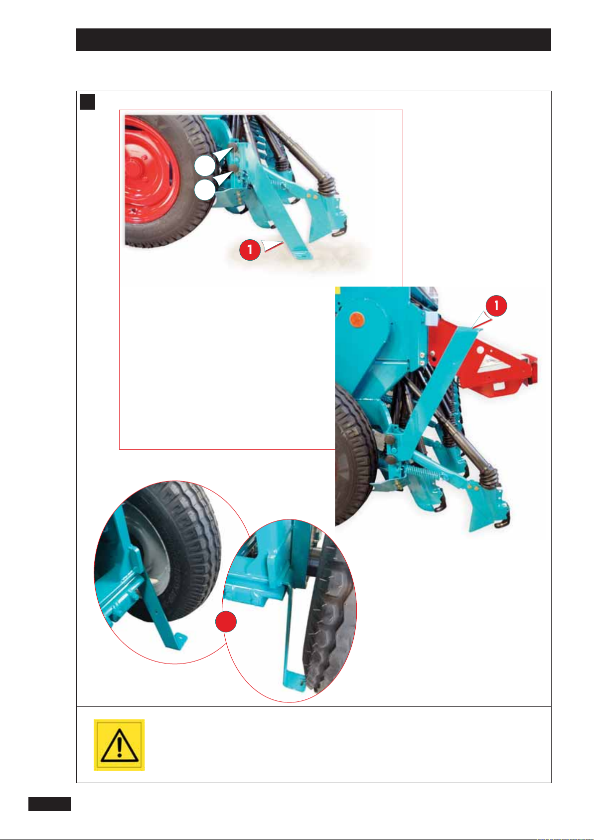
G
Béquille
BÉQUILLE DE REMISAGE
Molettes de blocage 2 pour la béquille 1 de
remisage
- Avant de décrocher le semoir bien véri er la stabilité de
la machine.
FR
- Ne jamais décrocher le semoir sans les béquilles
frontales 3.
La béquille 1 doit être positionnée sur un sol dur
(exemple Béton ).
BÉQUILLE EN POSITION SEMIS
- Veillez à bien bloquer les molettes
G
Parking stand
PARKING STAND
Locking knobs 2 for the parking stand 1.
- Before unhitching the seed drill, check that the machine
is stable.
- Never unhook the seed drill without the front stands 3.
The stand 1 should be positioned on hard ground
(e.g. concrete).
STAND IN DRILLING POSITION
- Make sure that the knobs are su ciently tightened
1
GB
Abstellstütze
G
BODENSTÜTZE FÜR DIE STILLLEGUNG
Schraubknöpfe 2 zum Arretieren der Abstellstütze
- Vor Abkuppeln der Drillmaschine Stabilität der Maschine
prüfen.
- Die Drillmaschine darf keinesfalls ohne die frontalen
Abstellstützen abgehängt werden 3.
Die Abstellstütze 1 muss auf festem Untergrund stehen
(z. B. Beton).
ABSTELLSTÜTZE IN ARBEITSPOSITION
- Sicherstellen, dass die Schraubknöpfe fest arretiert sind.
DE
1
2323
Page 26
Mise en route / Start-up / Inbetriebsetzung
H
1
2
I
2424
Il est recommandé de
réaliser l’alimentation
directement depuis la
batterie pour éviter toute
micro-coupure.
Veillez à garder propre la
prise hydraulique Push Pull.
-
+
We recommend that the unit
is connected directly to the
battery to ensure a constant
power supply.
Make sure that the hydraulic
push-pull connector is kept
clean.
Wir empfehlen eine
Direktversorgung ab
Batterie zur Vermeidung von
Mikroabschaltungen.
Push-Pull-Hydraulikstecker
sauber halten.
Page 27
Mise en route / Start-up / Inbetriebsetzung
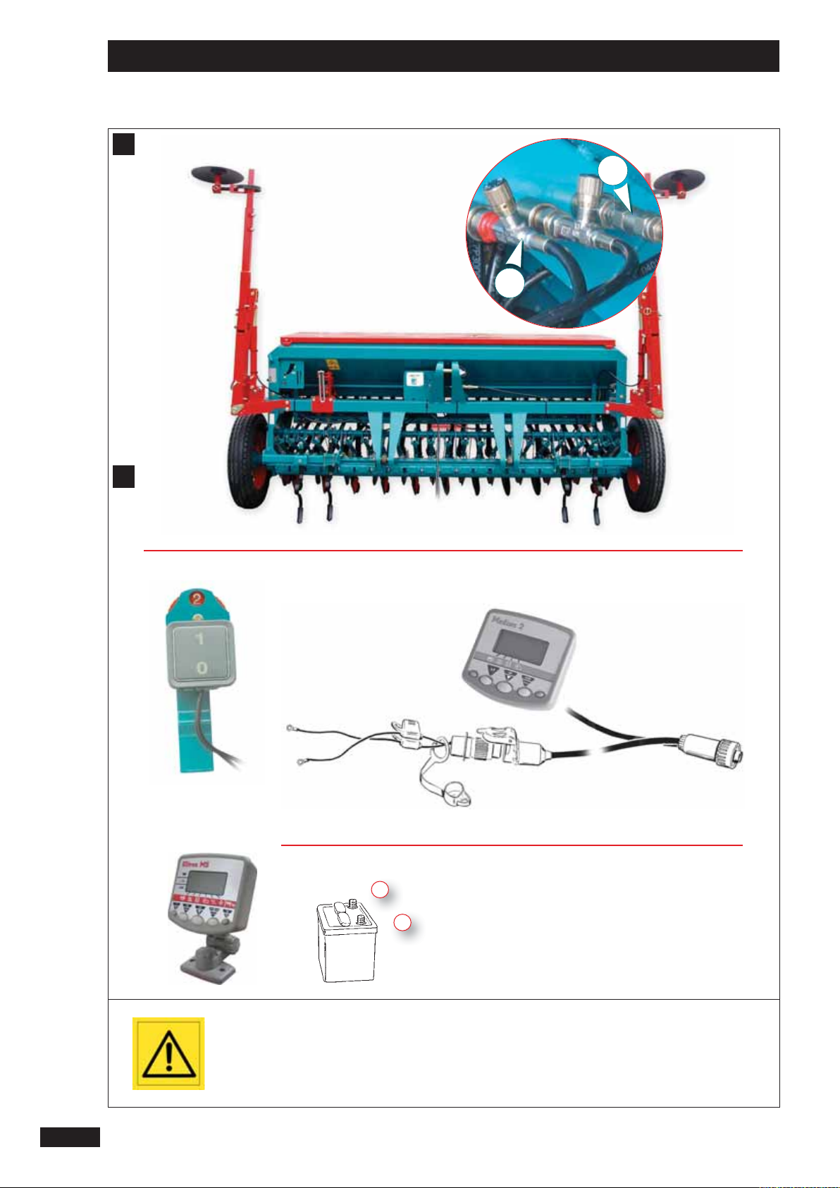
H
Branchement Hydraulique
I
Branchement Electrique / Electronique
FR
Le semoir ne nécessite pas d’hydraulique en standard.
Cependant il est possible que les options puissent nécessiter
un branchement hydraulique :
OPTION
TRACEUR
J
ALONNAGE DE PRÉLEVÉ
MODULATION HYDRAULIQUE DE TERRAGE 1 DE
H
Hydraulics connection
As standard, the seed drill does not require hydraulics.
However, optional tools may require a hydraulic connection:
OPTION
MARKER
P
RE-EMERGENCE TRAMLINING
HYDRAULIC DEPTH CONTROL MODULATION 1 DA
DISTRIBUTEUR
1 DE
SPREADER
1 DA
Le système de commande de jalonnage nécessite une alimentation en 12 volts continu.
(pôles + brun et
NFORMATIONS COMPLÉMENTAIRES SUR LE BOÎTIER ÉLECTRONIQUE DANS LE
I
MANUEL MEDION OU ULTRON MS.
I
Electrics/Electronics connection
The tramline control system requires a 12 V DC power supply
(poles + brown and - blue, marked).
ADDITIONAL INFORMATION ON THE ELECTRONIC UNIT IS CONTAINED IN
THE MEDION OR ULTRON MS MANUEL.
bleu, repérés)
-
1
GB
Hydraulikanschluß
H
Die Drillmaschine benötigt standardmäßig keinen Hydraulikanschluss.
Dennoch ist es möglich, dass bestimmte Optionen einen
Hydraulikanschluss voraussetzen:
OPTION
SPURANREISSER
V
ORLAUFMARKIERUNG
HYDRAULISCHE MODULATION DER ARBEITSTIEFE 1 DE
V
ERTEILER
1 DE
Elektrischer/elektronischer Anschluß
I
Das Schaltsystem der Fahrgassenschaltung erfordert eine
Gleichstromversorgung von 12 Volt
(Pole + braun und - blau, gekennzeichnet)
ZUSÄTZLICHE INFORMATIONEN ÜBER DAS ELEKTRONIKGERÄT IM HANDBUCH
S CONTAINED IN THE MEDION ODER ULTRON MS MANUEL.
DE
2525
Page 28
Mise en route / Start-up / Inbetriebsetzung
J
1
2626
Aucune personne ne doit
stationner sur la passerelle
pendant le semis et en
transport.
Make sure that no-one is
standing on the platform
when sowing or when
transporting the seed drill.
Niemand darf sich während
der Aussaat und beim
Transport auf dem Ladesteg
aufhalten.
Page 29
Mise en route / Start-up / Inbetriebsetzung
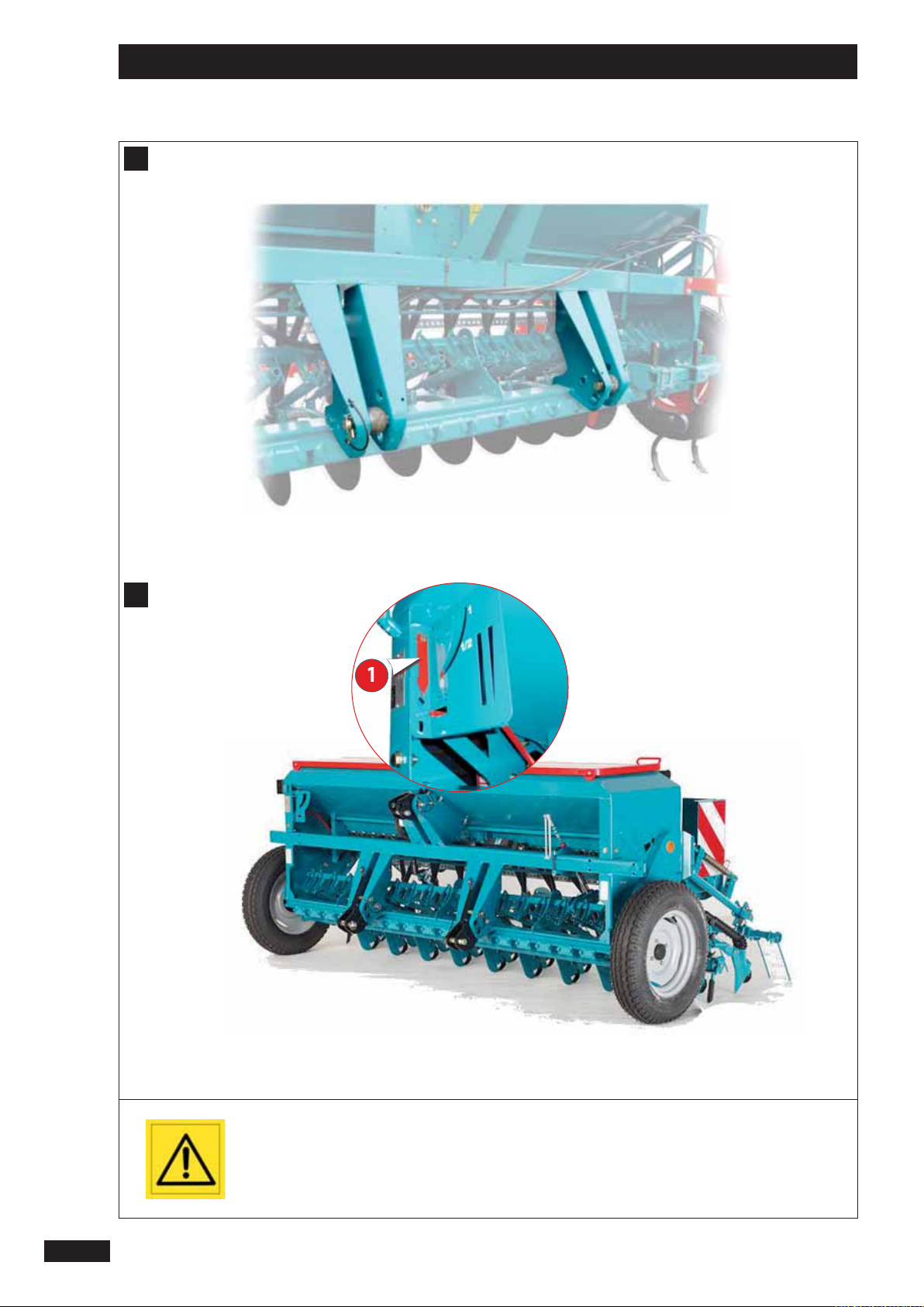
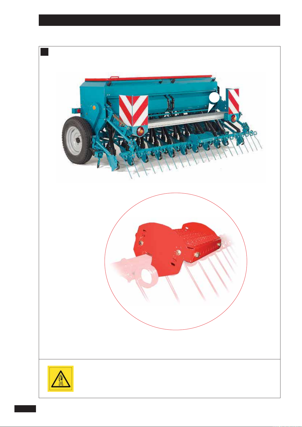
J
Passerelle de chargement
La passerelle 1 sert à faciliter le chargement lorsque le semoir est posé à terre, il est interdit de charger ou de monter
sur la passerelle lorsque le semoir est levé.
La marche située sur le pro lé de la herse de recouvrement
est réglable, a n de conserver l’horizontalité suivant les
réglages de la herse.
J
Loading platform
FR
1
GB
The platform 1 is used for easier loading when the seed drill
is placed on the ground. It is forbidden to load or climb onto
the platform when the seed drill is raised.
The step on the metal section of the covering harrow can
be adjusted, to keep it horizontal depending on the harrow
settings.
Ladesteg
J
Der Verbindungssteg 1 ermöglicht ein einfaches Beladen,
wenn die Drillmaschine auf dem Boden abgestellt ist. Es
ist verboten, den Verbindungssteg nach dem Anheben der
Sämaschine zu belasten bzw. zu betreten.
Die auf dem Pro l des Saatstriegels vorhandene Stufe kann
höhenverstellt werden, um die horizontale Ausrichtung
unter Berücksichtigung der Einstellungen des Saatstriegels
aufrechthalten zu können.
DE
2727
Page 30
Mise en route / Start-up / Inbetriebsetzung
2
3
4
K
4
2828
Attention à la rotation de
l’arbre d’agitateur.
Véri er qu’aucun corps
étranger ne se trouve dans
la trémie.
Il est conseillé de ne
pas laisser de graines à
l’intérieur de la trémie a n
d’éviter d’éventuels dégats
causés par les rongeurs.
Il est formellement interdit
de monter sur le semoir
pendant le travail et le
transport.
5
Beware of the rotating
agitator shaft.
Check that there are no
foreign bodies in the seed
box.
It is recommended not
to leave grain inside the
seed box to avoid possible
damage by rodents.
It is not recommended to
climb onto the seed drill
when it is working or during
transport.
Prüfen, ob sich keine
Fremdkörper im Saatkasten
be ndet.
Keine Körner im Saatkasten
lassen, um eventuelle
Beschädigungen durch
Nagetiere zu vermeiden.
Während der Arbeit nicht
in den Saatkasten greifen,»
rotierende Rührwelle».
Es ist formell verboten,
bei der Arbeit und
beim Transport auf die
Drillmaschine zu steigen.
Page 31

Mise en route / Start-up / Inbetriebsetzung
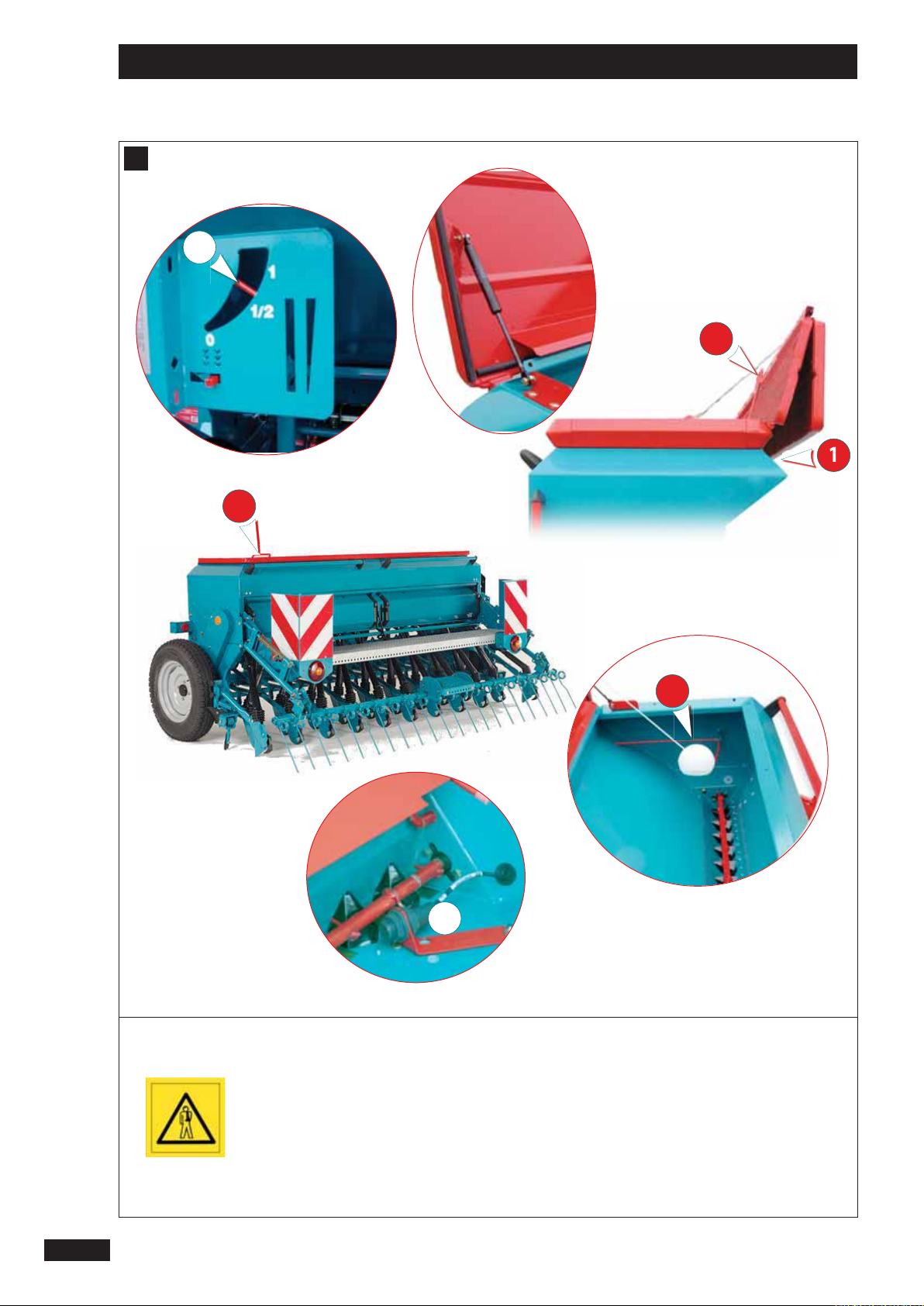
K
Remplissage de la trémie
MODÈLE 800 L
- Ouvrir le premier capot à l’aide de la poignée 1.
Le poser sur le deuxième capot avant d’ouvrir
complètement la trémie avec la deuxième poignée 2.
MODÈLE 450 L
FR
- Ouvrir le capot à l’aide de la poignée 3.
- Véri er qu’aucun corps étranger ne se trouve dans la
trémie.
Un indicateur de niveau mécanique 4 permet de véri er
le niveau de semence dans la trémie depuis le poste de
conduite.
Avec l’option ULTRON un capteur 5 de n de trémie réglable
est placé dans la trémie.
(position basse pour petite graine, position haute pour
grosse graine)
K
Filling the seed box
MODEL 800 L
- Open the rst cover with the handle 1.
Place on top of the second cover before opening the seed
box completely with the second handle 2.
MODEL 450 L
- Open the cover with the handle 3.
- Check that there are no foreign bodies in the seed box.
The seed level can be checked from the driver’s position by
means of a mechanical level indicator 4.
1
GB
With the optional ULTRON unit, an adjustable «seed box
low» 5 sensor is placed inside the seed box
(low position for small grain, high position for large grain).
Füllen des Saatkastens
K
MODELL 800 L
- Die erste Abdeckung mit dem Gri 1 ö nen.
Auf die zweite Abdeckung legen, bevor der Kasten mit
dem zweiten Gri 2 vollständig geö net wird.
MODELL 450 L
- Abdeckung mit Hilfe des Gri s 3 abnehmen.
- Prüfen, ob sich kein Fremdkörper im Saatkasten be ndet.
Ein mechanischer Füllstandanzeiger 4 ermöglicht die Kontrolle des Saatgutstandes ab Führerstand.
Mit der Sonderausrüstung ULTRON ist ein Fühler 5 «Leerer
Saatkasten» im Kasten angebracht.
(untere Stellung für kleines Korn, obere Stellung für dickes
Korn).
DE
2929
Page 32

Réglages / Settings / Einstellungen
2
A
2
1
1)
0
2)
3
3030
Suivre les indications
de réglage.
Follow the setting
instructions.
Die Hinweise zur Einstellung
befolgen.
Page 33

Réglages / Settings / Einstellungen
A
Réglage du débit
FR
2) CLAPET DE FOND
a) Réglage de la distribution
(voir chapitre 5 pour les valeurs de réglage et l’autocollant positionné dans le couvercle de la trémie)
1) TRAPPE DE DISTRIBUTION
- Lever ou baisser la trappe 1 en fonction des
recommandations.
- Encliqueter le ressort 2 dans l’encoche correspondante.
La trappe dispose de 3 positions
Repère 0 . Fermé
(semis 1 rang sur 2 par exemple)
1 . Petites graines < 8 kg/ha
2 . Grosses graines
A
Setting the ow
a) Setting the distribution
(see chapter 5 for the setting values and the sticker
placed on the hopper cover)
1) DISTRIBUTION SHUTTER
- Raise or lower the shutter 1 as recommended.
- Insert the spring 2 into the corresponding catch.
- Déplacer légèrement le levier 3 sur la droite et mettre au
cran correspondant.
Repère 1 . Céréales
2 . Céréales de gros diamètre
3 .
4 . Pois de conserve
5 . Pois
6 . Féverole
Maxi . Position basse, Vidange
Il faut rechercher à accompagner la graine avec l’ergot en
resserrant le plus possible le clapet de fond
(ex: repère 1 pour blé, orge).
Toutefois, si vous observez des projections de graines de
la distribution en permanence, placer le levier au cran
supérieur par rapport à la préconisation
(ex: repère 2 pour blé, orge).
2) BAFFLE PLATE
- Move lever 3 slightly to the right and set to the
appropriate mark.
Setting 1 . Cereal
2 . Large cereal
3 .
4 . Canning peas
5 . Peas
6 . Field beans
Max . Bottom position, Emptying
GB
2
into the corresponding catch.
Setting 0 . Closed
(sowing one row in two, for instance)
1 . Small grain < 8 kg/ha
2 . Large grain.
Einstellung der Saatmenge
A
a) Einstellung der Verteilung
(siehe Kapitel 5 für die Einstellwerte und den Aufkleber im
Tankdeckel)
1) AUSLAUFSCHIEBER
- Schieber 1 gemäß Empfehlungen heben oder senken.
- Feder 2 in die entsprechende Nut einklinken.
Der Schieber hat 3 Stellungen.
Markierung 0 . Geschlossen
(z.B. Aussaat alle 2 Reihen)
1 . Kleine Körner < 8 kg/ha
2 . Großkorn-Dibbelklappe.
The aim is to have the grain metered out by the feeding
roller by keeping the ba e plate as tightly closed as possible (e.g. setting 1 for wheat and barley).
However, if you notice a constant projection of grain from
the distribution system, set the lever one mark higher
than the recommendation
(e.g. setting 2 for wheat and barley).
DE
2) BODENKLAPPE
- Hebel 3 leicht nach rechts verschieben und in die
entsprechende Kerbe einrasten.
Markierung 1 . Getreide
2 . Getreide mit großem Durchmesser
3 .
4 . Erbsen für Konserven
5 . Erbsen
6 . Pferdebohnen
Maxi . Untere Stellung, Entleerung
Ziel ist, das Korn mit dem Nockenrad zu führen, indem die
Bodenklappe so stark wie möglich angezogen wird
(B. : Markierung 1 für Weizen, Gerste).
Sollten jedoch ständig Körner aus der Verteilung spritzen,
Hebel eine Kerbe höher stellen als empfohlen
(B. : Markierung 2 für Weizen, Gerste).
3131
Page 34

Réglages / Settings / Einstellungen
3
3
1
2
A
3)
b
a
4)
4
7
5
6
3232
Suivre les indications
de réglage.
Follow the setting
instructions.
Die Hinweise zur Einstellung
befolgen.
Page 35

Réglages / Settings / Einstellungen
A
3) SÉLECTION DE L’ERGOT
1
ᇗRoue standard pour céréales et grosses graines.
2
ᇗRoue ne pour petites graines.
La roue ne est toujours solidaire de l’arbre de
distribution .
La roue standard est connectée à la roue ne par
l’intermédiaire d’un verrouillage en laiton
3
ᇗPrendre la goupille sur la trappe du 1er boîtier à
droite.
- Pour sélectionner la roue de distribution:
a
Appuyer latéralement
ᇌ
b
Tourner pour ré-enclencher, eectuer l’opéra-
ᇌ
tion inverse : - repositionner
FR
4) VARIATEUR
- Mettre le repère déterminé à l’essai de débit à l’aide de la
molette 5, et du levier 6.
La lecture se fait au dessus de la partie plane 7.
4
Chaque changement de repère doit être suivi d’un
contrôle de débit.
Pour information, 3 graduations de vernier correspondent
à un écart d’environ 10 Kg/ha avec des céréales.
Repère de 0 à 90.
A
3) SELECTING THE PEG WHEEL
1
ᇗStandard wheel for cereals and large seeds.
2
ᇗFine wheel for small seeds.
The ne wheel is always secured to the metering
shaft. The standard wheel is connected to the ne
wheel by means of a brass interlock 4.
3
ᇗTake the pin located on the shutter of the 1st unit on
the right.
- To select the distribution wheel:
a
ᇌ
b
ᇌ
A
3) WAHL DES NOCKENRADES
1
ᇗNormalrad für Getreide und größere Körner.
2
ᇗFeines Rad für feinkörniges Saatgut.
Das feine Rad ist immer fest mit der Verteilerwelle
verbunden.
Das Normalrad ist mit dem feinen Rad über eine
Messing-Verriegelung 4 verbunden.
3
ᇗDen Splint auf dem Schieber des ersten Gehäuses
rechts nehmen.
- Zur Wahl des Särades:
a
ᇌ
b
ᇌ
Push sideways
Turn to re-engage, carry out the same operation in reverse to reposition
Seitlich drücken
Drehen zum Wiederauslösen, entgegengesetzten Arbeitsschritt durchführen: repositionieren
4) VARIATOR
- Using the knob 5 and the lever 6, position the marker
according to the results of the calibration test.
Read the setting above the at part 7.
Each time the marker is changed it must be followed by a
calibration test.
For information, 3 graduations on the adjustment scale
correspond to a dierence of approximately 10 kg / ha for
cereals.
Scale range from 0 to 90.
4) GETRIEBE
- Den bei der Abdrehprobe ermittelten Wert mit Hilfe des
Rädchens 5, und des Hebels 6 einstellen.
Das Ablesen der Werte erfolgt oberhalb des
abgeachten Teils 7.
Nach jedem Einstellwechsel muß eine
Streumengenkontrolle vorgenommen werden.
Zu Ihrer Information : 3 Nonius-Gradeinteilungen
entsprechen bei Getreide ungefähr einer Abweichung
von 10 kg/ha.
Markierung von 0 bis 90.
GB
DE
2
3333
Page 36

Réglages / Settings / Einstellungen
A
1
2
3
4
Pour un semis très précis, il
est nécessaire de réaliser un
essai de débit.
Attention à la précision de
votre balance.
A calibration test is
necessary for accurate
sowing.
Make sure that your scales
are accurate.
Für eine sehr präzise Saat
ist eine Abdrehprobe
erforderlich.
Die Waage muß genau sein.
3434
Page 37

Réglages / Settings / Einstellungen
A
b) Mise en place de l’essai de débit
FR
- Véri er que les distributions utilisées soient enclenchées.
- Procurez-vous une balance précise et un récipient.
- Avant d’e ectuer votre essai, véri er qu’il n’y ait personne
près du semoir.
DÉMARCHE
a ൺ Retirer les augets 1.
b ൺ Déverrouiller la barre à godet 2 et la baisser.
c ൺ Mettre les augets sous les distributions
d ൺ Prendre la manivelle 4 et l’engager sur l’arbre du
variateur.
A
b) Setting up the calibration test
- Use accurate scales and a container.
- Before carrying out the test, check that there is no-one
around the seed drill.
PROCEDURE:
- E ectuer votre essai de débit suivant les
recommandations des pages suivantes.
- Pour vider plus facilement la semence de l’auget, utiliser
la trappe 5.
- Remettre l’auget en position carter.
Ne pas oublier de verrouiller la barre à godets.
3
GB
- Check that the metering devices used are engaged.
- Carry out the calibration check in line with the
recommendations on the following pages.
- Use the shutter 5 to empty the seed tray more easily.
- Bring the tray back to the guard position.
2
a ൺ Remove the trays 1.
b ൺ Unlock the bucket bar 2 and lower it.
c ൺ Put the trays under the metering devices
d ൺ Take the crank 4 and engage it on the variator shaft.
A
b) Einrichten des Abdrehproben-Sets
- Besorgen Sie sich eine Präzisionswaage und einen
Behälter.
- Sich vor Durchführung der Abdrehprobe vergewissern,
daß sich niemand in Nähe der Drillmaschine aufhält.
VORGANGSWEISE
a ൺ Kippwannen 1 abnehmen.
b ൺ Kübelstange 2 entriegeln und absenken.
c ൺ Kippwannen unter die Saatgutverteiler platzieren 3.
Do not forget to lock the trough bar.
3
DE
- Kontrollieren, ob die Verteilungen in Gang gebracht sind.
- Die Abdrehprobe gemäß den Empfehlungen auf den
folgenden Seiten durchführen.
- Um das Entleeren des Saatguts der Mulde zu
vereinfachen, verwenden Sie die Klappe 5.
- Kippwanne zurück in die abgeschirmte Position bringen.
Bitte denken Sie daran, die Kübelstange zu
verriegeln.
d ൺ Kurbel 4 auf die Getriebewelle stecken.
3535
Page 38

Réglages / Settings / Einstellungen
A
1
1
2
5
1 tr / s
3,00 4,00
m
50 37,5
tr
6 7
3
4
ou - or - oder
x 40 = Kg / ha
2
8
Mini 5 Kg
Mini 150 Kg
3
9
ha = 0
4
Mini 100 tr
Mini 25 tr
10
5
+ 6 +
7
3636
Page 39

Réglages / Settings / Einstellungen
A
c) Réalisation de l’essai de débit
1) ESSAI EN POSTE FIXE
FR
Procéder au réglage de la distribution comme
1
l’indique la notice (clapet de fond, trappes etc...).
Mettre la graine dans la trémie le jour même du
2
semis (5 Kg minimum en Colza / 150 Kg minimum en
céréales) et réaliser l’essai à suivre.
Régler le variateur suivant le repère indicatif du
3
tableau (voir chapitre 5).
Amorcer la distribution : 25 tours de manivelle
4
minimum (l’auget peut être rempli), sauf pour le
colza 100 tours.
Faire l’essai en e ectuant le nombre de tours en
5
fonction de la largeur du semoir.
Nota : tourner régulièrement à 1 tour/seconde.
A
c) Carrying out the calibration test
1) FIXED UNIT TEST
Set the distribution as indicated in the manual
1
(ba e plate, shutters, etc.).
Put the seed in the hopper on the day of drilling
2
(minimum 5 kg for rape- minimum 150 kg for
cereals) and carry out the following test.
Set the variator to the mark indicated in the table
3
(see section 5).
Peser la quantité recueillie dans les augets avec une
6
balance précise.
Multiplier par 40 pour obtenir la quantité par ha ou
7
utiliser la réglette (voir page suivante).
Corriger le réglage du variateur (baisser complète-
8
ment le levier pour le ramener ensuite à la valeur
souhaitée).
Ramener le compteur d’hectares à zéro, après l’essai
9
de débit.
L’essai en condition réelle est le plus représenta-
10
tif.
Après un hectare de semis, refaire un essai de
véri cation
(procéder comme ci-dessus à partir de 5).
Weigh the quantity collected in the trays with an
6
accurate set of scales.
Multiply by 40 to obtain the quantity per hectare or
7
use the calculator (see next page).
Correct the variator setting (lower the lever
8
completely then bring it back up to the required
value).
GB
2
Start distribution: a minimum of 25 turns of the
4
crank (the trough may be lled), or 100 turns for
rape.
Carry out the test by completing the appropriate
5
number of turns for the width of the seed drill.
N.B. Turn steadily at 1 turn per second.
A
c) Durchführung der Abdrehprobe
1) PROBE IM STILLSTAND
Einstellung der Verteilung gemäß Anweisung
1
vornehmen (Bodenklappe, Schieber, usw..).
Füllen Sie das Saatgut am Tag der Aussaat selbst in
2
den Saatgutbehälter (mindestens 5 kg Raps/
mindestens 150 kg Getreide) und führen Sie den
folgenden Test durch.
Das Getriebe gemäß der in der Tabelle angegebenen
3
Markierung einstellen (vgl. Kapitel 5).
Die Verteilung in Gang bringen: mindestens 25
4
Kurbelumdrehungen (die Mulde kann gefüllt
werden), aber 100 Umdrehungen für Raps.
Probe vornehmen, indem eine der Drillmaschinen-
5
breite entsprechende Anzahl von Umdrehungen
vorgenommen wird.
Anmerkung: regelmäßig eine Umdrehung/Sekunde
vornehmen.
Reset the area meter to zero after the calibration
9
test.
The most representative test is one carried out
10
under real working conditions.
After sowing a hectare, carry out a further check
(proceed as above from step 5).
In den Mulden aufgefangene Menge mit einer
6
Präzisionswaage wiegen.
Mit 40 multiplizieren, um die Menge pro ha zu
7
erhalten oder Einstellscheibe benutzen (s. nächste
Seite).
Die Getriebe-Einstellung korrigieren (den Hebel
8
völlig senken und dann wieder auf den gewünschten
Wert stellen).
Den Hektarzähler nach der Abdrehprobe wieder auf
9
Null stellen.
Eine Probe unter reellen Bedingungen ist die
10
beste. Nach einem Hektar Aussaat eine Probe zur
Kontrolle durchführen (wie o.a. ab Punkt 5).
DE
3737
Page 40

Réglages / Settings / Einstellungen
4
1
A
3838
Page 41

Réglages / Settings / Einstellungen
A
2) ESSAI AVEC LA RÉGLETTE
Cette réglette vous permet de déterminer le nouveau
repère de variateur après votre 1er essai de débit.
FR
- Lire sur la ligne 4 le nouveau repère de variateur
correspondant à votre semence suivant vos conditions.
- Après un hectare de semis, refaire un essai de vérication
- Eectuer les réglages de la distribution et un essai
suivant les recommandations données dans les pages
précédentes.
Utilisation :
- Faire coïncider la ligne 1 du repère du variateur qui
a servi à votre 1er essai de débit avec la ligne 2 qui
correspond à la quantité recueillie à cet essai dans
l’auget en Kg.
- Sans bouger les disques de la réglette, repérer sur la ligne
3
votre débit souhaité sur la ligne Kg/ha.
A
2) TESTING WITH THE CALCULATOR
This calculator enables you to determine the new variator
setting after your rst calibration test.
- Set the distribution and carry out a test in line with the
recommendations given on the previous pages.
Use :
- Match line 1, the variator setting used for your rst
calibration test, up to line 2 which corresponds to the
quantity collected in the trough in kg during this test.
Si vous désirez changer le débit/ha avec la même semence
sur une autre parcelle, vous pouvez réutiliser la réglette
pour déterminer le nouveau repère du variateur en gardant la valeur de pesée du 1er essai de débit.
GB
- On line 4, read o the new variator setting
corresponding to your seed and conditions.
- After sowing a hectare, carry out a further check.
If you wish to change the seeding rate per hectare with
the same seed on another plot, you can use the calculator
again to determine the new variator setting by keeping
the weighed quantity obtained in the rst calibration test.
2
- Without moving the discs on the calculator, identify your
required seeding rate in kg/ha on line 3.
A
2) PROBE MIT DER EINSTELLSCHEIBE
Diese Einstellscheibe erlaubt Ihnen, die neue Getriebe-Markierung nach der 1. Abdrehprobe zu bestimmen.
- Die Einstellungen der Verteilung und eine Probe gemäß
den Empfehlungen auf den vorherigen Seiten durch
führen.
Benutzung :
- Die Linie 1 der Getriebe-Markierung, die für die
1. Abdrehprobe gedient hat, mit der Linie 2 in
Übereinstimmung bringen, die der bei dieser Probe in der
Mulde aufgefangenen Menge in kg entspricht.
- Ohne Verschiebung der Einstellscheibe auf der Linie 3
Ihre gewünschte Streumenge auf der Linie kg/ha suchen.
DE
- Auf der Linie 4 die neue Getriebe-Markierung ablesen,
die Ihrem Saatgut gemäß Ihren Bedingungen entspricht.
- Nach einem Hektar Aussaat eine neue Probe zur
Kontrolle durchführen.
Wollen Sie die Streumenge/ha mit dem gleichen Saatgut
auf einer anderen Parzelle ändern, können Sie erneut die
Einstellscheibe verwenden, um die neue Getriebe-Markierung unter Beibehaltung des gewogenen Wertes der 1.
Abdrehprobe zu ermitteln.
3939
Page 42

Réglages / Settings / Einstellungen
2
3
2
7
5
4
5
4
6
8
B
4040
Bloquer les traceurs en
transport.
Retirer la pression d’huile
avant dételage du semoir.
Secure the markers for
transport.
Release oil pressure before
unhitching the drill.
Spurreißer beim Transport
blockieren.
Öldruck vor Abkuppeln
der Drillmaschine
zurücknehmen.
Page 43

Réglages / Settings / Einstellungen
B
Traceurs
1) RELEVABLE À LA VERTICALE HYDRAULIQUEMENT
a) Mise en position de travail
Les traceurs sont conçus pour un marquage au centre du
tracteur. Ils sont pré-réglés usine.
- Mettre la pression hydraulique.
FR
- Après avoir positionné ce tube, (la position de la broche
4
sert de référence), bien bloquer les vis
Les traceurs sont pré réglés d’usine.
- Toutefois, si vous désirez ajuster ce réglage, déplacez le
support 7 du disque sur le tube.
La distance de la dernière ligne de semis au disque de
traceur est égale à une 1/2 largeur de travail plus un 1/2
écartement.
5
- Retirer la goupille 1 et dégager la broche 2 en tenant le
bras de traceur avec l’autre main.
Remettre la goupille 1 en position 3 pour
bloquer la broche.
- Baisser le premier traceur.
- Retirer la broche 4 et dévisser les vis 5 avec l’aide de la
manivelle de terrage 6 .
- Mettre le tube secondaire en position allongée.
(pour L > 3m)
B
Markers
1) HYDRAULIC VERTICAL LIFTING
a) Setting to working position
Markers are designed for tractor centreline marking. They
are pre-adjusted in the factory.
- Build up hydraulic pressure.
- Remove the clip 1 and pull out the pin 2 while holding
the marker arm with the other hand.
- Lower the rst marker.
Put the clip 1 back in position 3 to secure the
pin.
Il est possible de régler l’inclinaison du disque pour avoir
un marquage au sol plus ou moins important.
Quatre réglages sont disponibles en changeant la position de la cale d’orientation 8.
MONTAGE SUR L’OUTIL DE TRAVAIL DU SOL
Il est possible de monter les traceurs sur les Outils.
- Consulter votre revendeur.
GB
- After positioning that tube (by reference to the pin 4
position), lock the screws tight 5.
Markers were pre-adjusted in the factory.
- However, if you want to re ne that adjustment, move the
disc bracket 7 on the tube.
The distance between the last seed row and the marker
disc is equal to 1/2 working width + 1/2 spacing.
The slanting of the disc can be adjusted to obtain a more
or less visible marking.
Four settings are possible by changing the position of
orientation key 8.
ASSEMBLING THE CULTIVATING IMPLEMENT
The markers may be tted to the tool.
- Consult your dealer.
2
- Remove the pin 4 and loosen the screws 5 with the
crank 6.
- Set the secondary tube to the extended position.
(for L > 3m)
Spurreißer
B
1) KANN HYDRAULISCH IN DIE VERTIKALE GEBRACHT WERDEN
a) In Arbeitsstellung bringen
Die Spurreißer sind für eine Fahrgasseneinrichtung in
Schleppermitte gedacht. Sie sind im Werk voreingestellt.
- Hydraulikdruck anschalten.
-Splint 1 herausziehen und den Bolzen 2 freilegen,
wobei der Arm des Spurreißers mit der anderen Hand
gehalten werden muss.
- Den ersten Spurreißer absenken.
- Den Bolzen 4 entfernen und die Schrauben 5 mithilfe
der Schardruckverstellkurbel losschrauben
- Das Nebenrohr in Liegeposition bringen.
(für L > 3m)
Den Splint 1 zur Blockierung des Bolzens
wieder einsetzen 3
DE
- Nachdem das Rohr in die richtige Stellung gebracht
wurde (die Position des Bolzens
Anhaltspunkt), die Schrauben 5 fest anziehen.
Die Spurreißer sind im Werk voreingestellt.
- Sollten Sie diese Einstellung verändern wollen, versetzen
Sie den Scheibenhalter 7 auf dem Rohr.
Die Entfernung der letzten Saatreihe zur Spurreißerscheibe entspricht einer halben Arbeitsbreite plus einem
halben Abstand.
Es besteht die Möglichkeit, die Scheibenneigung zu verstellen, um eine schwächere oder stärkere Fahrgasseneinrichtung zu erzielen.
Vier Einstellungen sind durch das Versetzen des Paßstückes 8 möglich.
MONTAGE DES BODENBEARBEITUNGSGERÄTES
Es ist möglich, die Spuranreißer auf den Werkzeugen zu
6
montieren.
- Fragen Sie Ihren Fachhändler.
4
dient als
4141
Page 44

Réglages / Settings / Einstellungen
2
B
4242
La levée des traceurs ne doit
pas être brutale.
Réaliser les manœuvres de
demi-tour en bout de champ
traceurs relevés.
Pour le transport : raccourcir
le bras si la hauteur hors
tout est un handicap.
Les supports de disques
peuvent être retournés a n
de correspondre au gabarit
du semoir.
Markers should be raised
slowly.
Carry out end-of- eld
manoeuvres with the
markers raised.
Shorten the arm for
transport if the overall
height is too great.
The disc supports may be
turned around in order to
match the seed drill gauge.
Spurreißer nicht heftig
anheben.
Wenden am Feldende mit
angehobenen Spurreißern.
Beim Transport den Arm
verkürzen, wenn die
Gesamthöhe hinderlich ist.
Die Scheibenhalter können
umgedreht werden, um der
Drillmaschinenabmessung
zu entsprechen.
Page 45

Réglages / Settings / Einstellungen
B
b) Sécurité
FR
c) Fonctionnement
La sécurité du traceur fonctionne uniquement
en position travail.
Sécurité active ᇗ Dent souple amortisseur entre le
Sécurité passive ᇗ Boulon de sécurité 1 par cisaille-
Boulon de remplacement 2 sur le bras.
B
b) Safety
The marker safety device only operates
in working position.
Active safety ᇗ Flexible tine bu er between the arm
Passive safety ᇗ H10 x 90 class 6-8 safety
bras et le disque.
ment H 10 x 90
classe 6-8
and disc.
shearing bolt
1
- Mettre la pression ᇗ Les 2 traceurs se lèvent.
- Relâcher la pression ᇗ Un traceur se baisse.
- Mettre la pression ᇗ Le traceur baissé se lève.
- Relâcher la pression ᇗ L’autre traceur se baisse.
- Au travail laisser votre distributeur hydraulique du
tracteur en position ottante.
c) Operation
- Apply pressure ᇗ Both markers are raised.
- Release pressure ᇗ One marker is lowered.
- Apply pressure ᇗ The lowered marker is raised.
- Release pressure ᇗ The other marker is lowered.
GB
2
Replacement bolt 2 on the shaft.
B
b) Sicherheitsvorrichtung
Die Sicherheitsvorrichtung des Spurreißers funktioniert
ausschließlich in der Arbeitsstellung.
Aktive Sicherheit ᇗ Federzinken, Stoßdämpfer
Passive Sicherheit ᇗ Sicherheits-Scherbolzen 1
Ersatzbolzen 2 auf dem Arm.
zwischen Arm und Scheibe.
H 10 x 90 Klasse 6.8
- When working, leave the tractor’s spool valve in the oat
position.
DE
c) Funktionsweise
- Unter Druck setzen ᇗ Die beiden Spurreißer werden
angehoben.
- Druck wegnehmen ᇗ Ein Spurreißer senkt sich.
- Druck geben ᇗ Der gesenkte Spurreißer hebt
sich.
- Druck wegnehmen ᇗ Der andere Spurreißer senkt
sich.
Bei der Arbeit den Hydraulikverteiler des Schleppers in loser
Stellung lassen.
4343
Page 46

Réglages / Settings / Einstellungen
3
4
5
B
1
2
4444
Bloquer les traceurs en
transport.
Retirer la pression d’huile
avant dételage du semoir.
Secure the markers for
transport.
Release oil pressure before
unhitching the drill.
Spurreißer beim Transport
blockieren.
Öldruck vor Abkuppeln
der Drillmaschine
zurücknehmen
Page 47

Réglages / Settings / Einstellungen
B
2) RELEVABLE À LA VERTICALE MANUELLEMENT
a) Mise en position de travail
FR
La distance de la dernière ligne de semis au disque de
traceur est égale à une 1/2 largeur de travail plus un 1/2
écartement.
Les traceurs sont conçus pour un marquage au centre du
tracteur. Ils sont pré-réglés usine.
Pour chaque traceur il faut :
- Retirer la goupille et dégager la broche 2 en tenant le
bras de traceur avec l’autre main.
Remettre la goupille 1 en position 3 pour
bloquer la broche.
- Dévisser les vis 4 avec l’aide de la manivelle 5.
- Mettre le tube secondaire en position.
(3m depuis le milieu du semoir)
- Bien bloquer les vis 4.
B
2) HYDRAULIC VERTICAL LIFTING
a) Setting to working position
Markers are designed for tractor centreline marking. They
are pre-adjusted in the factory.
For each marker :
- Remove the clip 1 and pull out the pin 2 while holding
the marker arm with the other hand.
Put the clip 1 back in position 3 to secure the
pin.
Il est possible de régler l’inclinaison du disque pour avoir
un marquage au sol plus ou moins important.
GB
The distance between the last seed row and the marker
disc is equal to a 1/2 working width + a 1/2 spacing.
The slanting of the disc can be adjusted to obtain a more
of less visible marking.
2
- Loosen the screws 4 using the crank handle 5.
- Set the secondary tube in position.
(3m from the middle of the seed drill)
- Lock the screws 4 tightly.
B
2) KANN MANUELL IN DIE VERTIKALE GEBRACHT WERDEN
a) In Arbeitsstellung bringen
Die Spurreißer sind für eine Fahrgasseneinrichtung in
Schleppermitte gedacht. Sie sind im Werk voreingestellt.
Für jeden Spurreißer folgende Arbeitsschritte durchführen:
Stift 1 herausziehen und Raststift 2 durch Halten des
Spurreißerarms mit der anderen Hand herausnehmen.
Stift 1 wieder in die Anfangsposition
einsetzen, um den Raststift festzustellen.
- Schrauben 4 mit Hilfe der Kurbel 5 lockern.
- Sekundäres Rohr in Position bringen.
(3m ab Mitte der Drillmaschine)
- Schrauben 4 gut anziehen.
DE
Der Abstand der letzten Saatlinie zum Spurreißerrad ist
gleich 1/2 Arbeitsbreite plus 1/2 Reihenabstand.
Der Schrägstand des Rades ist einstellbar und erlaubt so
eine tiefe oder weniger tiefe Bodenmarkierung.
3
4545
Page 48

Réglages / Settings / Einstellungen
B
2
1
La levée des traceurs ne doit
pas être brutale.
Réaliser les manœuvres de
demi-tour en bout de champ
traceurs relevés.
Pour le transport : raccourcir
le bras si la hauteur hors
tout est un handicap.
Les supports de disques
peuvent être retournés a n
de correspondre au gabarit
du semoir.
Markers should be raised
slowly.
Carry out end-of- eld
manoeuvres with the
markers raised.
Shorten the arm for
transport if the overall
height is too great.
The disc supports may be
turned around in order to
match the seed drill gauge.
Spurreißer nicht heftig
anheben.
Wenden am Feldende mit
angehobenen Spurreißern.
Beim Transport den Arm
verkürzen, wenn die
Gesamthöhe hinderlich ist.
Die Scheibenhalter können
umgedreht werden, um der
Drillmaschinenabmessung
zu entsprechen
4646
Page 49

Réglages / Settings / Einstellungen
B
b) Sécurité
FR
c) Fonctionnement
La sécurité du traceur fonctionne uniquement en position
travail.
Sécurité passive ᇗ Boulon de sécurité 1 par cisaille-
Boulon de remplacement 2 sur le bras.
B
b) Safety
The marker safety device only operates
in working position.
Passive safety ᇗ H10 x 90 class 6.8 safety
Replacement bolt 2 on the shaft.
ment H 10 x 90
classe 6.8
shearing bolt
1
- Mettre la pression ᇗ Les 2 traceurs se lèvent.
- Relâcher la pression ᇗ Un traceur se baisse.
- Mettre la pression ᇗ Le traceur baissé se lève.
- Relâcher la pression ᇗ L’autre traceur se baisse.
- Au travail laisser votre distributeur hydraulique du
tracteur en position ottante.
c) Operation
- Apply pressure ᇗ Both markers are raised.
- Release pressure ᇗ One marker is lowered.
- Apply pressure ᇗ The lowered marker is raised.
- Release pressure ᇗ The other marker is lowered.
GB
2
B
b) Sicherheitsvorrichtung
Die Sicherheitsvorrichtung des Spurreißers funktioniert
ausschließlich in der Arbeitsstellung.
Passive Sicherheit ᇗ Sicherheits-Scherbolzen 1
Ersatzbolzen 2 auf dem Arm.
H 10 x 90 Klasse 6.8
- When working, leave the tractor’s spool valve in the oat
position.
DE
c) Funktionsweise
- Unter Druck setzen ᇗ Die beiden Spurreißer werden
angehoben.
- Druck wegnehmen ᇗ Ein Spurreißer senkt sich.
- Druck geben ᇗ Der gesenkte Spurreißer hebt
sich.
- Druck wegnehmen ᇗ Der andere Spurreißer senkt
sich.
Bei der Arbeit den Hydraulikverteiler des Schleppers in loser
Stellung lassen.
4747
Page 50

Réglages / Settings / Einstellungen
C
3
2
1
4848
Bien respecter la hauteur
de réglage du semoir par
rapport au sol.
Make sure that the drill
setting height in relation to
the ground is correct.
Einstellhöhe der
Drillmaschine in Bezug auf
den Boden einhalten.
Page 51

Réglages / Settings / Einstellungen
C
Réglage du terrage
FR
b) Soc Unidisc LS 230
a) Soc traînant LS 220
Réglage centralisé par un ou deux leviers 1.
Pour les deux éléments semeurs situés aux
extrémités à gauche et à droite, la profondeur se
règle en modi ant la position du ressort 2.
Il est possible de régler la butée basse des deux
éléments extérieurs à l’aide de la vis 3.
- En tournant le levier vers le repère minimum vous allez
soulager la pression de terrage sur les éléments semeurs.
Une graduation permet de valider le réglage de la profondeur .
C
Setting the depth control
a) Su olk coulter LS 220
Central adjustment is carried out using one or two crank
handles 1.
The depth is adjusted by modifying the spring
position 2 for the two coulter units on the left
and right.
The lower limit stop of the two external elements
may be adjusted using screw <3>.
L’Unidisc a été conçu pour travailler avec des sols recouvert de résidus ou en préparation de sol simpli é.
Réglage centralisé par le ou les leviers. (idem soc)
Pour les deux éléments semeurs situés aux
extrémités à gauche et à droite, la profondeur se
règle en modi ant la position du ressort 2.
b) Soc Unidisc LS 230
The Unidisc has been designed for work on simply prepared soil or in trashy conditions.
Central adjustment is carried out using one or more crank
handles. (idem soc).
The depth is adjusted by modifying the spring
position 2 for the two coulter units on the left
and right.
GB
2
- Turn the crank handle to minimum in order to release
the depth control pressure on the coulter units.
The depth control can be set using a graduated scale
Schardruckeinstellung
C
a) Schleppschar LS 220
Zentrale Einstellung über einen oder zwei Hebe
Die Arbeitstiefe der beiden Säorgane links und
rechts außen ist durch Veränderung der Position
der Feder 2 einstellbar.
Es ist möglich, den unteren Anschlag der beiden
äußeren Elemente mit der Schraube 3 einzustellen.
- Durch Drehen des Hebels in Richtung der kleinsten
Markierung wird der Schardruck der Säorgane entlastet.
Anhand der Skala kann die Tiefenführung eingestellt
werden
DE
b) Unidisc-Schar LS 230
Das Unidisc-Schar ist für die Arbeit auf Böden mit P an-
1
zenresten oder für die vereinfachte Bodenvorbereitung
bestimmt.
Zentrale Einstellung über den bzw. die Hebel.
(Siehe schar).
Die Arbeitstiefe der beiden Säorgane links und
rechts außen ist durch Veränderung der Position
der Feder 3 einstellbar.
4949
Page 52

Réglages / Settings / Einstellungen
2
D
3
b
a
3
5050
Les réglages de la herse de
recouvrement se font après
avoir réglé sa profondeur de
semis.
The covering harrow is to be
adjusted after setting the
sowing depth.
Die Einstellungen der
Saategge erfolgen nach
Einstellung ihrer Saattiefe.
Page 53

Réglages / Settings / Einstellungen
D
Réglage de la Herse de recouvrement
FR
b) Herse à dents niveleuses
a) Herse à dents droites
RÉGLAGE DE L’INCLINAISON DES DENTS 1 :
Positions permettant d’avoir un dégagement plus ou
moins important en fonction de la présence de débris
végétaux.
- Retirer la broche 2 servant de butée et changer de trou.
RÉGLAGE PRESSION
- Tourner le ressort
a
vers le bas ᇗ Pression
b
vers le haut ᇗ Soulagement
Position neutre au milieu
POSITION DE LA DENT PAR R APPORT AU SOC :
Réglage usine
D
Adjusting the covering harrow
a) Straight-tine harrow
ADJUSTING THE TINE ANGLE 1:
Positions enabling you to have a larger or smaller clearance depending on the presence of trash.
3
RÉGLAGE DE L’INCLINAISON DES DENTS 1:
Positions permettant de changer l’angle d’attaque des
dents :
- Retirer la broche 2 et changer de trou.
Quelques soient les conditions, la dent niveleuse doit
travailler parallèle au sol ou légèrement sur la pointe
au-dessus de la profondeur de semis.
RÉGLAGE PRESSION
- Tourner le ressort
a
vers le bas ᇗ Pression
b
vers le haut ᇗ Soulagement
Position neutre au milieu
b) Levelling tine harrow
ADJUSTING THE TINE ANGLE 1 :
Positions enabling you to change the angle of attack of
the teeth:
- Remove the pin 2 and change hole.
3
GB
2
- remove the locking pin 2 and change hole.
ADJUSTING THE PRESSURE
- Turn the spring
a
downwards ᇗ increase the pressure
b
upwards ᇗ reduce the pressure
Neutral position in the middle.
POSITION OF TINE IN RELATION TO THE SHARE :
Factory adjustment
Einstellung des Saatstriegels
D
a) Striegel mit geraden Zinken
EINSTELLUNG DER ZINKENNEIGUNG 1:
Positionen, mit denen der Reihenabstand je nach vorhandenen Panzenresten größer oder kleiner eingestellt
werden kann.
- Den als Anschlag dienenden Stift 2 herausziehen und
Loch wechseln.
EINSTELLUNG DES DRUCKS 3:
- Feder drehen
a
nach unten ᇗ mehr Druck
b
nach oben ᇗ weniger Druck
Neutralstellung in der Mitte.
3
Whatever the conditions may be, the levelling tine must
be parallel to the ground or slightly on the tip above the
sowing depth.
ADJUSTING THE PRESSURE
- Turn the spring
a
downwards ᇗ increase the pressure
b
upwards ᇗ reduce the pressure
Neutral position in the middle.
b) Striegel mit Planierzinken
EINSTELLUNG DER ZINKENNEIGUNG 1:
Positionen, mit denen der Angriswinkel der Zinken geändert werden kann:
- Den Stift 2 herausziehen und Loch wechseln.
Die Planierzinke muß unabhängig von den Bedingungen
parallel zum Boden oder leicht «auf der Spitze» über der
Saattiefe arbeiten.
EINSTELLUNG DES DRUCKS 3:
- Feder drehen
a
nach unten ᇗ mehr Druck
b
nach oben ᇗ weniger Druck
Neutralstellung in der Mitte.
3
DE
STELLUNG DER ZINKE IN BEZUG AUF DAS SCHAR :
Werkseitig eingestellt.
5151
Page 54

Réglages / Settings / Einstellungen
2
E
5252
a b
Pour le bon fonctionnement
du jalonnage assurezvous que le branchement
électrique soit correctement
réalisé.
For the tramline system to
function well, make sure that
the electrical connections
are correctly made.
Zur guten Funktion der
Fahrgassenschaltung muß
der elektrische Anschluß
korrekt sein.
Page 55

Réglages / Settings / Einstellungen
E
Dispositif de marquage
a) Principe
b) Fonctionnement
JALONNAGE POST LEVÉE
FR
1
Consiste à ménager des passages en vue de traitements
ultérieurs avec des outils de largeur multiple de la largeur
de travail du semoir.
E
Tramlining
a) Principle
Consists of creating tramlines with a view to subsequent
treatment with implements whose width is a multiple of
the working width of the seed drill.
Débrayage à distance de 2 à 4 distributions correspondant à la voie de l’outil d’épandage ou de traitement.
JALONNAGE PRÉ LEVÉE (OPTION)
Marquage au sol de la voie déterminée pour tout passage
avant levée de la culture.
INDICATEUR MÉCANIQUE
Position a = semis.
ᇌ
Position b = jalonnage.
ᇌ
b) Operation
POST-EMERGENCE TRAMLINING
Two to four metering devices corresponding to the width
of the implement used for spreading or crop treatment
are disengaged by remote control
PRE-EMERGENCE TRAMLINING (OPTIONAL)
Tramlines marked in the soil before crop emergence
2
1
2
GB
2
Fahrgassenanlage
E
a) Prinzip
Einrichten von Fahrgassen für spätere Behandlungen
mit Geräten, deren Breite ein Vielfaches der Drillmaschinen-Arbeitsbreite ist.
MECHANICAL INDICATORS
Position a = seed drilling
ᇌ
Position b = tramlining
ᇌ
b) Funktionsweise
NACHAUFLAUFMARKIERUNG
Fernabschaltung von 2 bis 4 Nockenrädern gemäß der
Spur des Streu- oder Behandlungsgerätes.
VORAUFLAUFMARKIERUNG (SONDERAUSRÜSTUNG)
Markierung vor Panzenaufgang der für alle Fahrten
festgelegten Spur auf dem Boden.
MECHANISCHER POSITIONSINDIKATOR
Position a = Saatausbringung.
ᇌ
Position b = Fahrgassenmarkierung.
ᇌ
1
2
DE
5353
Page 56

Réglages / Settings / Einstellungen
E
3 4 5 1 2 3 4 5 1 2
3 5
4m
10m
5 5
3 6
5454
3 4 5 6 1 2 3 4 5 6 1 2 3
2m 4m
12m
6 6
Page 57

Réglages / Settings / Einstellungen
E
m m
3 932
12
15 5 3
5 3
42
18
21 7 4
24
4 12 3 2
16
20 5 3
24
28 7 4
32
36 9 5
63
84
42
63
84
2
5555
Page 58

Réglages / Settings / Einstellungen
E
5656
Maintenir en pression
quelques secondes le levier
du distributeur hydraulique.
Maintain the pressure on
the hydraulic valve lever for
a few seconds after turning
the hydraulic.
Hebel des
Hydrauliksteuerventils
einige Sekunden lang
drücken.
Page 59

Réglages / Settings / Einstellungen
E
c) Jalonnage de post levée
COMMANDE ELECTRIQUE
Commande à volonté les distributions débrayables.
Au moment du marquage :
- Appuyer sur l’interrupteur 1
Après le marquage :
- Appuyer sur l’interrupteur 0
Avec la mollette il est possible de compter les passages du
semoir.
1
FR
E
c) Post-emergence tramlining
ELECTRICAL CONTROL
Freely controls the clutch-operated distribution.
When marking :
- Press the switch 1
After marking :
- Press the switch 0
It is possible to count the number of drilling runs using the
wheel.
E
c) Nachauaufmarkierung
ELEKTRISCHE BETÄTIGUNG
1
1
GB
DE
2
Steuert nach Wunsch die abschaltbaren Nockenräder.
Bei Markierung :
- Schalter drücken 1
Nach dem Markieren :
- Schalter drücken 0
Mit dem Rädchen können die Durchgänge der Drillmaschine gezählt werden.
5757
Page 60

Réglages / Settings / Einstellungen
E
5858
Attention de ne pas trop
croiser les tubes de descente.
Make sure that the coulter
tubes are not crossed too
much.
Darauf achten, daß die
Saatrohre nicht zu stark
gekreuzt werden.
Page 61

Réglages / Settings / Einstellungen
E
COMMANDE ÉLECTRONIQUE
FR
RÉGLAGE DE LA VOIE SI NÉCESSAIRE :
Le comptage des passages est réalisé avec des capteurs.
Les capteurs sont positionnés soit sur les traceurs ou soit
sur l’attelage oscillant.
Lors des manoeuvres en bout de champ, le comptage se
fait de manière automatique.
- Voir le fonctionnement du boîtier sur la notice MEDION
et ULTRON MS.
E
ELECTRONIC CONTROL
The number of runs completed is counted using the
sensors.
The sensors are located either on the markers or on the
linkage.
The counter moves on automatically as the drill is manoeuvred at the end of the eld.
Le débrayage des distributions ayant une position xe sur
la trémie, il sut de changer les tubes de descente 1 correspondant aux éléments semeurs choisis et de les placer
sous la distribution débrayée.
- Repérer les éléments semeurs à condamner pour le
marquage.
- Déboîter le haut de leur tube de descente.
- Les emboîter sous les distributions qui sont munies de
l’embrayage.
GB
ADJUSTING THE TRACK, IF REQUIRED :
As the disengaged metering device is in a xed position on
the seed box, the tubes 1 relating to the selected coulter
units just need to be changed and placed beneath the
disengaged metering unit.
- Identify the coulter units to be shut o for marking.
- Disconnect the top of the coulter tubes.
2
- Refer to the MEDION and ULTRON MS instructions to
operate the unit.
E
ELEKTRONISCHE BETÄTIGUNG
Die Zählung der Durchgänge erfolgt mit Hilfe von Sensoren.
Die Sensoren benden sich entweder an den Spurreißern
oder am Pendelausgleich.
Bei den Manövern am Feldende erfolgt die Zählung
automatisch.
- Vgl. Gerätefunktion auf der MEDION und ULTRON MS.Anweisung.
- Connect them beneath the clutch-operated metering
units.
DE
EINSTELLUNG DER SPUR, FALLS NÖTIG :
Da die Ausrückkupplung der Nockenräder eine feste
Stellung auf dem Saatkasten einnimmt, genügt es, die
den gewählten Säelementen entsprechenden Saatrohre
1
auszutauschen und sie unter den abgeschalteten
Nockenräder anzubringen.
- Die für die Fahrgasseneinrichtung abzuschaltenden
Säelemente kennzeichnen.
- Oberen Teil ihres Saatrohres aushängen.
- Unter den Nockenrädern mit Kupplung anbringen.
5959
Page 62

Réglages / Settings / Einstellungen
3
2
2
4
E
b
6060
Ne pas circuler dans la zone
de fonctionnement des
jalonneurs de pré-levée.
Keep clear of the working
area of the preemergence
tramlining system.
Aufenhalt im Arbeitsbereich
der Vorau auf-Markierer
untersagt.
Page 63

Réglages / Settings / Einstellungen
E
d) Jalonnage de pré levée
FR
RÉGLAGE DE LA VOIE
DISQUES DE PRÉ LEVÉE
- Appuyer sur le levier 1 pour débloquer les bras
Les disques de pré levée fonctionnent en simultanée avec
le jalonnage de post levée.
La voie de marquage doit correspondre avec celle des
rangs débrayés.
Le marquage au sol est réglable en faisant accrocher plus
ou moins les disques au sol.
Il est conseillé de faire prendre le disque au bord du dernier rang semé an de jeter la terre sur les rangs débrayés.
- Mettre le bras 2 en position transport 3, après chaque
utilisation et au transport
E
d) Pre-emergence tramlining
PRE-EMERGENCE DISCS
- Push lever 1 to release arms 2.
The pre-emergence discs operate at the same time as the
post-emergence tramlining system.
The width between the tramlines must match the distance between the disengaged rows.
Voie possible de 1,60 m à 2,50 m.
2
Le réglage de la voie est possible :
a
En coulissant l’axe 4 du disque par rapport au bras.
b
En inversant le bras 2 gauche et droit pour changer de
déport.
ADJUSTING THE TRACK
The tramline track can be adjusted between 1.6 m and
2.5 m.
This is done by :
a
sliding the disc shaft 4 through the arm,
b
reversing the LH and RH arm 2 to change oset.
GB
2
Ground marking can be adjusted by altering disc penetration in the soil.
We recommend engaging the disc at the edge of the last
row sown in order to move the soil into the empty rows.
- Put the arm 2 into the transit position 3 after use and
for transport.
E
d) Vorauaufmarkierung
MARKIERSCHEIBEN
- Auf den Hebel 1 drücken, um die Arme 2 freizugeben.
Die Markierscheiben arbeiten gleichzeitig mit der Nachauaufmarkierung.
Die Markierspur muß der der abgeschalteten Reihen
entsprechen.
Die Bodenmarkierung ist durch mehr oder weniger starkes Eindringen der Scheiben in den Boden einstellbar.
Wir empfehlen den Einsatz der Scheibe am Rand der letzten besäten Reihe, damit die Erde auf die nicht besäten
Reihen geworfen wird.
SPUREINSTELLUNG
Spur einstellbar von 1,60 m bis 2,50 m
Die Einstellung der Spur ist möglich :
a
Durch Verschieben des Bolzens 4 der Scheibe in Bezug
auf den Arm.
b
Durch Umkehren des linken und rechten Arms 2 zum
Ändern der Versetzung.
DE
- Arm 2 nach jeder Benutzung und beim Transport in
Transportstellung 3 bringen.
6161
Page 64

Réglages / Settings / Einstellungen
F
G
a
b
2
Il est impératif de vider la
trémie après le travail, pour
éviter les dégâts causés par
les rongeurs.
1
It is essential to empty the
seed box after sowing to
avoid rodent damage.
Saatkasten nach Einsatz
zum Schutz vor Nagetieren
unbedingt völlig entleeren.
6262
Page 65

Réglages / Settings / Einstellungen
F
Débrayage demi-semoir
X
G
Vidange de la trémie
FR
Le désaccouplement de la noix centrale entre les 1/2 arbres
de distribution est possible pour correspondre au passage de
jalonnage. Seul le côté gauche est débrayable.
- Pour débrayer
a
Pousser
b
Tourner
F
Disengaging half of the seed drill
The centre sleeve between the distribution half-shafts may
be uncoupled to match up with the tramlining. Only the
left-hand side may be disengaged.
- To disengage:
a
Push
b
Twist
La vidange de la trémie se fait dans l’auget 1.
- Positionner l’auget sous la distribution et abaisser le
levier 2 à fond vers le bas.
- Pour stopper l’écoulement de la graine alors que la
trémie n’est que partiellement vide, lever légèrement le
levier sans chercher à le mettre en position haute.
G
Emptying the seed box
The seed box is emptied into the tray 1.
- Position the tray beneath the metering devices and push
the lever 2 fully down.
- To stop the grain ow when the seed box is only partly
empty, lift the lever very slightly.
GB
2
Abschalten 1/2 Drillmaschine
F
Die Zentralnuß zwischen den Halbwellen der Verteilung
kann entkuppelt werden, um dem Fahrgassendurchgang zu
entsprechen. Nur die linke Seite kann ausgekuppelt werden.
- Zum Auskuppeln
a
Schieben
b
Drehen
Entleeren des Saatkastens
G
Der Saatkasten wird in die Mulde 1 entleert.
- Die Mulde unter der Verteilung anbringen und den Hebel
2
ganz nach unten drücken.
- Zum Stoppen des Kornusses bei nur teilweise
entleertem Kasten den Hebel leicht anheben, ohne zu
versuchen, ihn nach oben zu stellen.
DE
6363
Page 66

Entretien / Maintenance / Wartung
B
2
6464
Bien respecter les
périodicités de vidange du
variateur.
Ne jamais graisser les
distributions et les tubes de
descente.
Change the variator
oil according to the
recommended frequency.
Never grease the metering
devices or the coulter tubes.
Die Ölwechselabstände
für das Ölbadgetriebe
einhalten.
Niemals die Saatausläufe
und Saatrohre schmieren.
Page 67

Entretien / Maintenance / Wartung
A
Nettoyage
- Souer l’intérieur trémie
- Laver le semoir sans haute pression
Pour le nettoyage et entretien, porter lunette de
protection et gants pour éviter toutes blessures.
S’il reste de la semence porter un masque anti-poussière pour éviter toute inhalation.
B
Graissage
- Procéder régulièrement à un graissage de la machine en
début et n de campagne.
1
Articulation de vérin de traceur au centre (2) 200
heures
2
Manivelle de terrage (1 ou 2) 100 heures
3
Modulation de terrage (option) (2) 100 heures
A
Cleaning
-Clean inside the seed box with a blower.
- Wash the seed drill without using high pressure.
For cleaning and maintenance, wear protective
glasses and gloves to prevent injury.
If there is left-over seed, wear a dust mask to prevent inhaling dust.
FR
- Huiler les ressorts de débrayage pour repérage (il est
préférable de pulvériser du dégrippant).
- Huiler la chaîne de distribution.
- Graisser les pignons de compteur d’ha (une noix de
graisse).
- Vérier le niveau d’huile du variateur (semoir horizontal),
ajuster le niveau au point rouge avec de l’huile de boîte
de vitesses automatiques. ATF - DEXTRON II D
- Eectuer la vidange tous les 500 ha ou tous les 2 ans si la
surface n’est pas eectuée.
Les socs robustes en fonte grise sont à changer en cas
d’usure importante risquant d’endommager la partie tôle.
GB
- Lubricate the tramlining clutch springs (preferably by
spraying on an antiseize compound).
- Lubricate the drive chain.
- Grease the areameter pinion (knob of grease).
- Check the oil level in the variator (with drill horizontal)
and top up to the red dot with ATF - DEXTRON II D
automatic gearbox oil.
B
Lubrication
- Grease the machine regularly at the beginning and end
of the season.
1
Centre line marker actuator joint (2) 200 hours
2
Depth control crank handle (1 or 2) 100 hours
3
Variable depth control (option) (2) 100 hours
Reinigung
A
- Saatkasten innen sauberblasen.
- Drillmaschine ohne Hochdruck waschen
Zur Vermeidung von Verletzungen beim Reinigen
und bei der Instandhaltung Schutzbrille und
Handschuhe tragen.
Sind Saatgutrückstande vorhanden, eine
Staubschutz maske tragen.
Schmierung
B
- Maschine regelmäßig am Anfang und Ende der
Kampagne schmieren.
1
Zylindergelenk des Spurreißers in der Mitte (2) 200
Stunden
2
Schardruck-Kurbel (1 oder 2) 100 Stunden
3
Ablagemodulation (Option) (2) 100 Stunden
- Change the oil every 500 hectares, or every 2 years at the
most.
Change the strong grey cast iron shares in the event of signicant wear which may damage the sheet metal section.
DE
- Kennzeichnung-Auskupplungsfedern ölen (am besten
Gleitschutzmittel aufsprühen).
- Antriebskette ölen.
- Zahnräder des Hektarzählers schmieren (etwas Fett)
- Ölstand des Getriebes kontrollieren (Drillmaschine
waagerecht), bis zum roten Punkt mit Öl für
automatische Getriebe (ATF -DEXTRON II D) ergänzen.
- Ölwechsel alle 500 ha oder alle 2 Jahre, wenn diese
Fläche nicht erreicht wird.
Die robusten Schare aus grauem Gußeisen müssen ausgewechselt werden, wenn ihre Abnutzung auf das Stahlblech
übergreifen zu droht.
3
6565
Page 68

Entretien / Maintenance / Wartung
1
2
3
4
C
6mm
6666
Page 69

Entretien / Maintenance / Wartung
C
Distribution
• Ne jamais laisser de la semence dans la trémie pendant
une longue période.
FR
Il est conseillé de contrôler et de régler si nécessaire après
chaque période de semis.
- Positionner le levier des clapets de fond au repère 1.
- Ouvrir les trappes 1 et les clapets de fond 2 pendant la
période de remisage.
• Ne jamais graisser les distributions et les tubes de des-
cente.
CONTRÔLE
Un réglage défectueux des clapets de fond 2 peut provoquer un surdosage en cours de semis.
C
Distribution
• Never leave seed in the hopper for any length of time.
- Open the distribution shutters and 1 the bottom aps
2
during storage.
• Never lubricate distribution chutes and pipes.
CHECK
Faulty adjustment of the bottom aps 2 may induce oversowing.
- Véri er visuellement dans un premier temps la distance
entre le clapet et la roue à ergot (6mm).
- Si nécessaire, mettre une cale 3 de 6 mm entre le clapet
et la roue à ergot grosse graine (entre les ergots).
Ajuster la distance à l’aide de la vis 4.
GB
It is recommended to check and adjust if necessary after
each sowing campaign.
- Set the bottom ap lever to index 1.
- First perform a visual check of the distance between the
valve and the peg wheel (6mm).
- If necessary, put a 6-mm block 3 between the ap and
the large seed studded wheel (between studs).
Adjust clearance with the screw 4.
3
Verteilung
C
• Das Saatgut nicht über längere Zeit im Saatkasten las-
sen.
- Die Schieber 1 und die Bodenklappen 2 während der
Abstellzeit ö nen.
• Die Verteilungen und die Saatrohre nicht schmieren.
KONTROLLE
Eine schlechte Einstellung der Bodenklappen 2 kann beim.
Säen zu einer Überdosierung führen.
DE
Es ist empfehlenswert, diese Einstellung nach jeder Saatperiode zu überprüfen und gegebenenfalls neu einzustellen.
- Die Hebel der Bodenklappen auf Markierung 1 einstellen.
- Führen Sie zunächst eine visuelle Prüfung des Abstands
zwischen der Klappe und dem Nockenrad (6 mm) durch.
- Wenn nötig, einen 6 mm-Keil 3 zwischen Klappe und
das Nockenrad für größere Körner schieben (zwischen
die Nocken).
Den Abstand mit Hilfe der Schraube 4 justieren.
6767
Page 70

Entretien / Maintenance / Wartung
D
6868
Page 71

Entretien / Maintenance / Wartung
D
Caractéristiques techniques
a) Identi cation
Lors de la prise en charge de votre machine, notez en page 2 les informations suivantes :
Numero de série de la machine / Type de machine / Accessoires
b) Caractéristiques
SEMOIR SE/SL 300 SX/PL 300 SX/PL 400
ARGEUR (m) 33 4
L
N
OMBRE DE RANGS 21 / 25 21 / 25 29 / 33
CARTEMENT (cm) 14,2 / 12,0 14,2/ 12,0 13,7 / 12,0
E
ONTENANCE TRÉMIE (l) 450 800 1100
C
ÉHAUSSE (l) 700 1000 1350
R
AUTEUR DE REMPLISSAGE (m) 1,25 1,43 1,43
H
POIDS (INDICATIF) (kg) 550 750 950
UISSANCE MINI (cv) 70 80 100
P
RESSION (BARS) PNEU 600X16
P
ISTANCE ENTRE L’AXE D’ATTELAGE ET LE
D
CENTRE DE GRAVITÉ (m) d = (mm)
D
ISTANCE (D )AVEC CHAPES OSCILLANTES d = (mm) 635 635 635
NEU 10.0-75/15,3
P
Poids à vide = Consulter la plaque constructeur sur la machine
D
Technical speci cations
2 3,5 -
-
3 (OPTION) 3,5
525 525 525
FR
GB
a) Identi cation
Note the following information on receipt of your machine :
Machine number / Machine type / Accessories
b) Speci cations
SEED DRILL SE/SL 300 SX/PL 300 SX/PL 400
IDTH (m) 34
W
NUMBER OF ROWS 21 / 25 21 / 25 29 / 33
PACING (cm) 14,2 / 12,0 14,2/ 12,0 13,7 / 12,0
S
EED BOX CAPACITY (l) 450 800 1100
S
OPPER EXTENSION (l) 700 1000 1350
H
EIGHT OF DRILL FULLY EQUIPPED (m) 1,25 1,43 1,43
W
EIGHT (INDICATION (kg) 550 750 950
W
INIMUM POWER (hp) 70 80 100
M
RESSURE (BAR) TYRE 600X16
P
ISTANCE BETWEEN THE LINKAGE PIN
D
AND THE CENTRE OF GRAVITY (m) d = (mm)
YRE 10.0-75/15.3
T
2 3,5 -
3 (OPTIONAL) 3,5
525 525
DISTANCE (D) WITH FLOATING CLEVIS HITCHES d = (mm) 635 635 635
Tare weight = see manufacturer’s plate on the machine
Technische Daten
D
a) Identi zierung
Bei Abnahme Ihrer Maschine folgende Informationen vermerken :
Maschinennummer / Maschinentyp / ZubehörteilE
b) Technische Daten
3
DE
DRILLMASCHINE SE/SL 300 SX/PL 300 SX/PL 400
REITE (m) 33 4
B
R EIHENZAHL 21 / 25 21 / 25 29 / 33
BSTAND (cm) 14,2 / 12,0 14,2/ 12,0 13,7 / 12,0
A
AATKASTENINHALT (l) 450 800 1100
S
T RICHTERAUFBAU (l) 700 1000 1350
ÜLLHÖHE (m) 1,25 1,43 1,43
F
EWICHT (HINWEISEND) (kg) 550 750 950
G
INIMALLEISTUNG (hp) 70 80 100
M
EIFENDRUCK (BAR) REIFEN 600X16
R
BSTAND ZWISCHEN ANKUPPLUNGSACHSE
A
UND SCHWERPUNKT (m) d = (mm)
EIFEN 10.0-75/15.3
R
2 3,5 -
OPTION) 3,5
-
3 (
525 525 525
A BSTAND (D) MIT PENDELAUSGLEICHSVORRICHTUNG d = (mm) 635 635 635
Leergewicht = das Typenschild auf der Maschine einsehen
6969
Page 72

Entretien / Maintenance / Wartung
E
CE
7070
cx
Page 73

Entretien / Maintenance / Wartung
E
Positions Autocollants
Des étiquettes adhésives relatives à la sécurité ont été placées sur votre machine.
Leur but est de contribuer à votre sécurité et à celle d’autrui.
- Lisez leur contenu et contrôlez leur emplacement.
- Revoyez les étiquettes ainsi que les instructions
contenues dans la notice d’instructions avec l’opérateur
de la machine.
- Gardez les étiquettes propres et lisibles.
Remplacez-les lorsqu’elles sont détériorées.
E
Sticker positions
FR
GB
Warning notices relating to safety are axed to your machine.
Their aim is to contribute to your safety and to the safety of
others.
- Know their contents and check their location.
- Review the safety notices as well as the instructions
contained in this operating manual.
- If any safety notices become illegible or lost they should
be replaced.
Sicherheitsaufkleber
E
Sicherheitsaufkleber sind auf Ihrer Maschine angebracht.
Sie sollen zu Ihrer Sicherheit und der anderer Personen
beitragen.
- Sie sorgfältig lesen und ihre Anbringung kontrollieren.
3
DE
- Sicherheitsaufkleber und Bedienungsanweisung mit
dem Benutzer der Maschine durchgehen.
- Schilder sauber und lesbar halten.
Beschädigte Aufkleber auswechseln.
7171
Page 74

Equipements / Accessories / Ausrüstungen
3
4
2
A
B
7272
Chaque équipement
correspond à des conditions
particulières à adapter au
sol et au semis.
Every accessory relates to
special conditions which
need to be adapted to the
soil and the seed.
Jede Ausrüstung entspricht
besonderen Bedingungen
und ist dem Boden und der
Saat anzupassen.
Page 75

Equipements / Accessories / Ausrüstungen
A B
Limiteur de profondeur pour soc traînant
(contrôle de la profondeur en sol «souple» ou hétérogène)
FR
Uniband pour soc traînant
(semis étale 6-8 cm)
MONTAGE DU LIMITEUR
- Retirer les deux écrous 1 H10 du soc
- Monter le limiteur
3
2
- Régler la hauteur du limiteur par rapport à la pointe du
soc au sol et serrer.
RÉALISATION, RÉGLAGE
- Pour déterminer la cote de réglage du limiteur, vous
pouvez vous aider d’une cale 4 dont sa hauteur
correspond à la profondeur de semis désiré.
Toutefois, si les conditions de sol sont diciles, il est conseillé
de mettre quelques centimètres en plus.
Avec cet équipement, il est aussi conseillé de mettre plus de
pression de terrage aux éléments semeurs.
A
Depth limiter for Suolk coulter
(depth control in loose or composite soils)
FITTING THE LIMITER
- Remove the two H10 nuts 1 from the share
- Fit the limiter
3
2
- Adjust the height of the limiter in relation to the point of
the share to the ground and tighten.
LE MONTAGE SE FAIT À L’ARRIÈRE DU SOC SANS CLÉS SPÉCIALES
- Nettoyer les socs avant le montage
- Mettre l’uniband
- Mettre la broche élastique
B
Uniband for Suolk coulter
1
2
(sowing a 6-8 cm wide band)
MOUNTED AT THE REAR OF THE SHARE WITHOUT THE NEED FOR SPECIAL
TOOLS.
- Clean the share before mounting
- Fit the uniband
- Fit the spring pin
1
2
GB
ADJUSTMENT
- To determine the limiter setting, a block 4 whose height
corresponds to the required sowing depth may be used
In dicult soil conditions, however, you are advised to add
on a few centimetres.
With this equipment, it is also recommended to increase the
depth control pressure on the coulter units.
Sätiefenbegrenzer Für Schleppschar
A
(Tiefenkontrolle in “lockerem” oder heterogenem Boden)
MONTAGE DES BEGRENZERS
- Die beiden Muttern 1 H10 des Schars 2 abnehmen
- Den Begrenzer montieren
3
- Höhe des Begrenzers in Bezug auf die Scharspitze am
Boden einstellen und anziehen.
AUSFÜHRUNG, EINSTELLUNG
- Zur Ermittlung des Einstellwertes des Begrenzers kann
ein Paßstück 4 benutzt werden, dessen Höhe der
gewünschten Saattiefe entspricht.
Bei schwierigen Bodenbedingungen sollten jedoch einige
Zentimeter mehr vorgesehen werden.
Uniband Für Schleppschar
B
(Bandsaat 6-8 cm)
DIE MONTAGE ERFOLGT AUF DER RÜCKSEITE OHNE SPEZIALWERKZEUG
- Schare vor Montage reinigen
- Uniband 1 anbringen
- Federstift anbringen
2
DE
4
Mit dieser Ausrüstung sollte ein höherer Schardruck an den
Säelementen benutzt werden.
7373
Page 76

Equipements / Accessories / Ausrüstungen
C
1
Après avoir mis le compteur
à zéro, tourner la molette
en sens inverse jusqu’à
l’encliquetage.
After resetting the meter to
zero, turn the knob the other
way until a click is heard.
Nach Nullstellung des
Zählers das Rädchen
bis zum Einrasten in
entgegengesetzte Richtung
drehen
7474
Page 77

Equipements / Accessories / Ausrüstungen
C
Compteur d’hectares
D
Electronique
FR
FONCTIONNEMENT
Situé sur le côté gauche du semoir.
La lecture de la surface est directe pour la largeur de travail
de 3 m et 4 m
Chi res noirs ᇗ Hectares
Chi res rouges ᇗ Ares
La remise à zéro s’e ectue en tournant la molette 1.
Après avoir inscrit les zéros faire un quart de tour en arrière,
jusqu’à entendre un “click”.
C
Areameter
OPERATION
LOCATED IN THE CASING ON THE LEFT-HAND SIDE OF THE SEED DRILL.
The surface area can be read directly for a working width 3
m and 4 m
Black gures ᇗ Hectares
Red gures ᇗ Ares
The meter is reset by turning the wheel 1.
After having entered the zeros make a reverse quarter turn
until you hear a “click”.
LE SEMOIR PEUT ÊTRE ÉQUIPÉ SOIT :
- d’un boîtier Médion :
Vitesse d’avancement
ჹ
Compteur d’hectares
ჹ
Jalonnage
ჹ
- d’un boîtier Ultron MS :
le boîtier a en plus:
Le contrôle de la rotation de la distribution
ჹ
L’ alarme de n de trémie
ჹ
La modulation de débit
ჹ
L’ assistance à l’essai de débit
ჹ
Montage et utilisation :
Voir les notices du Médion ou de l’Ultron MS jointes.
D
Electronics
THE SEED DRILL MAY BE FITTED WITH:
- either with a Medion unit :
Forward speed
ჹ
Areameter
ჹ
Tramlining
ჹ
- or with a Ultron MS unit :
the unit also comes with:
Metering device rotary control
ჹ
End-of-hopper alert
ჹ
Modulated application rate
ჹ
Calibration test assistance
ჹ
Installation and use :
See the accompanying instructions for the Medion or Ultron
MS unit.
GB
Hektarzähler
C
FUNKTIONSWEISE
Im Gehäuse auf der linker Drillmaschinenseite
Direktablesung der Fläche für die Arbeitsbreite von 3 m und
4 m
Chwarze Zahlen ᇗ ha
Rote Zahlen ᇗ Ar
Nullstellung durch Drehen des Rädchens 1.
Nach Eintragen der Nullen eine Vierteldrehung nach hinten
durchführen, bis ein „Klick“ ertönt.
Elektronik
D
DIE SÄMASCHINE KANN ÜBER FOLGENDE AUSSTATTUNGEN VERFÜGEN:
- einem Medion Schaltkasten :
Fahrtgeschwindigkeit
ჹ
Hektarzähler
ჹ
Markierung
ჹ
- oder mit einem Ultron MS Schaltkasten ausgestattet
sein :
Das Elektronikgerät hat folgende Zusatzfunktionen :
Kontrolle der Rotation der Saatgutverteilung
ჹ
Alarm Trichterstand
ჹ
Dosierungsänderung
ჹ
Hilfsvorrichtung für die Abdrehprobe
ჹ
Montage und Bedienung :
Siehe beiliegende Bedienungsanleitungen für Medion bzw.
Ultron MS.
DE
4
7575
Page 78

Equipements / Accessories / Ausrüstungen
E
-
+
7676
Suivre les instructions de
montage.
Comply with assembly
instructions.
Montageanweisungen
befolgen
Page 79

Equipements / Accessories / Ausrüstungen
E
Modulation de débit MS
Voir notice jointe.
E
Flow modulation MS
FR
GB
see enclosed instructions.
Saatmengenverstellung MS
E
s. beiliegendes Handbuch
DE
4
7777
Page 80

Equipements / Accessories / Ausrüstungen
F
H
G
7878
Suivre les instructions de
montage.
Comply with assembly
instructions.
Montageanweisungen
befolgen.
Page 81

Equipements / Accessories / Ausrüstungen
F
Réhausse
H
Chapes d’attelage oscillantes
FR
Une réhausse est disponible pour le Semoir .
Montage :
Voir notice jointe.
Agitateur souple
G
- Utiliser l’agitateur souple dans le cas ou la semence a un
très mauvais écoulement.
Exemple : Ray Grass de ferme
Montage :
- Prendre la bavette caoutchouc et l’enrouler autour du
doigt d’agitateur suivant le schéma.
- Attention au sens de rotation.
F
Seed box extension
An extension is available for the seed drill.
Assembly :
instructions attached.
G
Rubber agitator
Cet équipement permet dans le cas d’un relevage non ottant un meilleur suivi du terrain.
H
Floating linkage cover
This equipment allows better ground following for
a non oating linkage.
GB
- Use the rubber agitator in cases where the seed ows
poorly (e.g. farm rye-grass).
Fitting :
- Take the rubber ap and wind it round the agitator
nger as shown.
- Beware of the direction of rotation.
Aufsatz
F
Für die Sämaschine ist ein Aufsatz verfügbar.
Montage :
Siehe beiliegende Anleitung.
Elastische Rührwelle
G
- Elastische Rührwelle verwenden, wenn das Saatgut
schlecht ausläuft (z. B. Landraygras)
Montage :
- Gummischutz gemäß Plan um Rühr nger wickeln.
- Auf Drehrichtung achten.
Schwingkupplungsvorrichtung
H
Diese Ausrüstung bietet eine bessere Anpassung an die
Bodenverhältnisse bei nicht schwimmend gelagerter Hubvorrichtung.
DE
4
7979
Page 82

Equipements / Accessories / Ausrüstungen
I
8080
Véri er qu’il n’y ait
personne autour du
semoir avant d’agir sur
l’hydraulique.
Check that there is
nobody near the drill
before operating the
hydraulics.
Sichergehen, dass
sich niemand im
Maschinenbereich be ndet,
bevor Sie an der Hydraulik
arbeiten.
Page 83

Equipements / Accessories / Ausrüstungen
I
Modulation de terrage
Remarque
La pression maximum de terrage peut se déterminer par la
course maximum du vérin (butée mécanique).
La pression mini sera donnée par la course de la manivelle.
- Il faut brancher l’hydraulique sur un distributeur
hydraulique double eet.
PRINCIPE DE FONCTIONNEMENT :
Quand on actionne le vérin tige sortie, on augmente le
terrage.
A l’inverse quand on rentre la tige du vérin, alors on retourne
au réglage initial de la profondeur qui est réalisé par la
manivelle.
La position de la cheville sur la chape du vérin permet de
déterminer la profondeur maxi.
I
Adjusting the depth control
FR
GB
NB :
The ram stroke limit may determine the maximum depth
pressure (mechanical stop).
The crank stroke will provide the minimum pressure.
- Connect the hydraulics to a double action valve.
OPERATING PRINCIPLE
The depth control increases when the extended actuator rod
is actioned.
When the actuator rod is retracted using the crank handle
you return to the initial depth settings.
The maximum depth is determined by the pin position on
the actuator casing.
Schardruckverstellung
I
Anmerkung
Der maximale Ablagedruck kann über den maximalen
Zylinderhub (mechanischer Anschlag) bestimmt werden.
Der minimale Ablagedruck ergibt sich aus dem Kurbelhub.
- Hydraulikanschluss an einem doppelwirkenden
Hydraulikverteiler vornehmen.
DE
4
FUNKTIONSPRINZIP :
Wird der Zylinder bei ausgezogenem Stift ausgelöst, erhöht
sich der Schardruck.
Ist der Zylinderkolben dagegen eingezogen, stellt sich die
ursprüngliche Arbeitstiefe mit Hilfe der Kurbel wieder ein.
Die Stellung des Stifts an der Zylinderabdeckung bestimmt
die maximale Arbeitstiefe.
8181
Page 84

Equipements / Accessories / Ausrüstungen
1
I
J
H
I
I
I
8282
Page 85

Equipements / Accessories / Ausrüstungen
J
Roues de réappui
a) Avant toutes choses, vérier que votre semoir est
d’aplomb et que la rampe de semis soit à 325 mm
(+ ou -25 mm) voir chapitre 1- G.
b) Ensuite ajuster à l’aide de la l’écrou à anneau 1 la posi-
tion de la roulette.
La cote H ainsi que la pression sur la rampe de semis
détermineront la profondeur de semis.
Note :
la chape de réglage de la roulette a trois repères.
la lecture de la position de réglage se fait au dessus du
support de la roulette
FR
Le réglage entre la rangée avant et la rangée arrière
doit être identique.
Si après réglage vous n’arrivez pas à ce résultat, vérier l’aplomb de votre ensemble de semis, contrôler
la profondeur de semis régulièrement pendant le
semis.
- I -
S
EMIS DE SURFACE
COLZA BLÉ FEVROLES
H
se fait sous le support de la roulette
J
Packer wheels
a) First of all, check that your seed drill is vertical and the
b) Then adjust the position of the wheel with the ring nut 1.
Note:
the wheel adjustment clevis has three marks.
reading of the adjustment position is performed above the
wheel support
se fait sous le support de la roulette
ERBE ORGE POIS
………
coulter bar is at 325 mm (± 25 mm) see Chapter 1- G.
The dimension H as well as the pressure on the coulter bar
will determine the drilling depth.
- I -
S
URFACE DRILLING
RAPE WHEAT HORSE BEANS
G
RASS BARLEY PEAS
………
- II -
S
EMIS DE CÉRÉALES
- II -
C
EREAL DRILLING
III -
-
S
EMIS PROFONDS
III -
-
D
EEP DRILLING
GB
The setting between the front row and the back row
must be identical.
If, after the adjustment, you do not achieve this
result, check that your drilling unit is vertical. Regularly check the drilling depth while drilling.
Andruckrollen
J
a) Zunächst müssen Sie die lotrechte Position Ihrer Säma-
schine prüfen. Danach müssen Sie kontrollieren, ob die
Saatgutteilbreite 325 mm (+ oder -25 mm) beträgt, siehe
Kapitel 1- G.
b) Danach passen Sie die Position des Rads über die Ring-
mutter 1 an.
Das Maß H sowie der Druck auf der Saatgutteilbreite
bestimmen die Sätiefe.
Hinweis:
Das Einstellgelenk des Rads verfügt über drei Markierungen.
Das Ablesen der Einstellposition erfolgt über dem Radhalter/
unter dem Radhalter
- I -
S
AATAUSBRINGUNG
AUF DER
BERFLÄCHE
O
RAPS WEIZEN ACKERBOHNEN
G
se fait sous le support de la roulette
RAS GERSTE ERBSEN
………
- II -
S
AATAUSBRINGUNG
VON GETREIDE
III -
T
IEFE
AATAUSBRINGUNG
S
DE
Die Einstellung zwischen der vorderen Reihe und
der hinteren Reihe muss identisch ausfallen.
Sollte dieses Ergebnis nach erfolgter Einstellung
nicht erlangt werden, prüfen Sie die lotrechte Ausrichtung Ihrer gesamten Aussaat sowie die Sätiefe
während der Aussaat in regelmäßigen Abständen.
4
8383
Page 86

Equipements / Accessories / Ausrüstungen
K
1
1
2
L
Véri er qu’il n’y ait
personne autour du
semoir avant d’agir sur
l’hydraulique.
Check that there is
nobody near the drill
before operating the
hydraulics.
Sichergehen, dass
sich niemand im
Maschinenbereich be ndet,
bevor Sie an der Hydraulik
arbeiten
8484
Page 87

Equipements / Accessories / Ausrüstungen
K L
E aces traces de roue de tracteur
FR
E ace trace de roue de semoir
Pour une utilisation en solo, il est conseillé d’utiliser les
e aces traces (2 pour chaque roue).
On peut régler :
LA POSITION EN LARGEUR
- Desserrer les 2 vis 1 et positionner chaque dent derrière
les roues du tracteur.
LA POSITION EN HAUTEUR
- Desserrer les vis 2 et régler la profondeur de travail pour
chaque soc.
K
Tractor wheel track eradicators
For solo use, it is recommended to use track erasers (2 for
each wheel).
You can adjust :
THE WIDTH POSITION
Dans certaines conditions, il peut être nécessaire d’utiliser
des e aces traces pour les roues du semoir.
L
Seed drill wheel track eradicator
Under certain conditions, it may be necessary to use track
eradicators for the seed drill wheels.
GB
- Untighten the 2 screws 1 and position each tine behind
the tractor wheels.
THE HEIGHT POSITION
- Untighten the 2 screws 2 and adjust the working depth
of each coulter.
Löscht die Spuren der Schlepperräder
K
Bei Solo-Anwendung wird empfohlen, die Spurlockerung (2
für jedes Rad) einzusetzen.
Folgende Parameter sind einstellbar :
STELLUNG IN DER BREITE
- Die beiden Schrauben 1 lockern und jeden Zinken
hinter die Schlepperräder positionieren.
STELLUNG IN DER HÖHE
- Die beiden Schrauben 2 lockern und Arbeitstiefe für
jede Schar einstellen.
Löscht die Spuren der Drillmaschinenräder
L
Unter bestimmten Bedingungen kann es erforderlich sein,
die Spuren für die Räder der Sämaschine zu löschen.
DE
4
8585
Page 88

Tableaux de réglage / Setting charts / Einstelltabellen
324
A
Rappel pré-réglages
1
Trappes (3 positions)
2
Ergots (2 positions)
3
Clapet de fond (6 positions)
3
Variateur
(Repères 0 à 90)
Pre-setting reminder
1
Shutters (3 positions)
2
Feeding rollers (2 positions)
3
Ba e plate (6 positions)
4
Variator
(Scale from 0 to 90)
Zur Erinnerung:
Voreinstellungen
1
Schieber (3 Stellungen)
2
Nockenräder (2 Stellungen)
3
Bodenklappe (6 Stellungen)
4
Ölbadgetriebe
(Markierungen 0 bis 90)
DEGBFR
8686
Page 89

Tableaux de réglage / Setting charts / Einstelltabellen
B
Tableaux de débit
Seeding rate charts
DEGBFR
Sämengentabellen
Les réglages des tableaux ne sont
donnés qu’à titre indicatif.
- Véri er votre débit hectare, pour
plus de précision (voir chapitre 2).
25
25
23
3
3
4
4
23
21
21
19
19
33
33
31
31
29
29
27
27
12
13
14,2
14,2
15,7
15,7
12,1
12,1
12,9
12,9
13,7
13,7
14,8
14,8
The chart settings are provided as an
indication only.
- Check your seeding rate per
hectare for grea ter accuracy (see
section 2).
HIVER
HIVER
B
B
LÉLÉHIVER
LÉLÉHIVER
B
B
INTER
WHEAT
INTER
WHEAT
W
W
INTER
WHEAT
INTER
WHEAT
W
W
INTERWEIZEN
INTERWEIZEN
W
W
INTERWEIZEN
INTERWEIZEN
W
W
VARIÉ
TÉ
/
VARIETY
/S
TÉ
/
VARIETY
60
60
70
70
80
80
90
90
100
100
110
110
120
120
130
130
140
140
150
150
160
160
170
170
180
180
190
190
200
200
210
210
220
220
230
230
240
240
250
250
260
260
270
270
280
280
290
290
300
300
/ T
/ T
REATMENT
ORTE
/S
ORTE
O
RVANTIS
O
RVANTIS
REATMENT
/
/
A
USTRAL
A
USTRAL
12 12,5 13 13,6 14 14,3 15 15,7 16 16,7
12 12,5 13 13,6 14 14,3 15 15,7 16 16,7
19 20 20 21 22 22 23 25 25 26
19 20 20 21 22 22 23 25 25 26
22 23 24 25 26 26 27 29 29 31
22 23 24 25 26 26 27 29 29 31
25 26 27 29 29 30 32 33 34 35
25 26 27 29 29 30 32 33 34 35
28 30 31 32 33 34 35 37 38 39
28 30 31 32 33 34 35 37 38 39
32 33 34 36 37 38 39 41 42 44
32 33 34 36 37 38 39 41 42 44
35 36 38 39 40 41 43 45 46 48
35 36 38 39 40 41 43 45 46 48
38 39 41 43 44 45 47 49 50 52
38 39 41 43 44 45 47 49 50 52
41 43 44 46 47 48 51 53 54 56
41 43 44 46 47 48 51 53 54 56
44 46 47 49 51 52 54 56 57 59
44 46 47 49 51 52 54 56 57 59
47 49 51 53 54 55 57 60 60 63
47 49 51 53 54 55 57 60 60 63
50 52 54 56 57 58 60 63 64 66
50 52 54 56 57 58 60 63 64 66
53 55 56 59 60 61 63 66 67 69
53 55 56 59 60 61 63 66 67 69
55 57 59 61 63 64 66 69 70 72
55 57 59 61 63 64 66 69 70 72
58 60 62 64 66 67 69 72 72 75
58 60 62 64 66 67 69 72 72 75
60 62 64 67 68 69 72 74 75 78
60 62 64 67 68 69 72 74 75 78
63 65 67 69 71 72 74 77 78 80
63 65 67 69 71 72 74 77 78 80
65 67 69 72 7
65 67 69 72 7
67 70 72 74 76 77 79 82 83
67 70 72 74 76 77 79 82 83
70 72 74 76 78 79 82 85
70 72 74 76 78 79 82 85
72 74 76 79 80 81 84
72 74 76 79 80 81 84
74 76 78 81 83 84
74 76 78 81 83 84
76 78 80 83 85
76 78 80 83 85
78 80 83
78 80 83
80 82 85
80 82 85
82 84
82 84
VARIÉ
T
RAITEMENT
T
RAITEMENT
B
B
EHANDLUNG
EHANDLUNG
12
13
Die Einstellungen in den Tabellen
dienen nur als Hinweis.
- Die von Ihnen gewählte Sämenge
zwecks größerer Präzision
kontrollieren (vgl. Kapitel 2)
37477 79 8183
37477 79 8183
AVOINE OAT HAFER 88 NAVET TE RAPE RÜBSEN 104
B
LÉ WHEAT WEIZEN 89-90 OEILLET TE OIL POPPY SCHLAFMOHN 105
C
OLZA RAPE RAPS 91-92 ORGE BARLEY GERSTE 106-107
F
ÉTUQUE FESCUE SCHWINGEL 93-94 PHACÉLIA PHACELIA PHAZELIA 108
ÉVEROLE FIELD BEANS ACKERBOHNEN 95-96 POIS PEAS ERBSEN 109
F
IN LINSEED LEINSAAT 97 RADIS RADISH RADIESCHEN 110
L
OTIER CORNICULE BIRD'S-FOOT TREFOIL FLÜGELGINSTERWEIDE 98 RAY GRASS RYE-GRASS RAY -GRAS 111-112
L
UPIN LUPIN LUPINE 99 TRÈFLE CLOVER KLEE 113
L
UZERNE LUCERN LUZERNE 100 TRITICALE TRITICALE TRITICALE 114
L
AÏS MAIZE MAIS 101 VESCE VETCH WICKE 115
M
M
OUTARDE BLANCHE WHITE MUSTARD WEISSER SENF 102-103
8787
Page 90

Tableaux de réglage / Setting charts / Einstelltabellen
A
A
W
W
V
ARIÉTÉ
T
RAITEMENT
VOINE
VOINE
W
W
/ V
HIVER
HIVER
INTER
OAT
INTER
INTERHAFER
INTERHAFER
ARIETY
/ T
/ S
ORTE
E
REATMENT
G
:
VORA
/ B
AUCHO
OAT
EHANDLUNG
:
12 12,5 13 13,6 14 14,3 15 15,7 16 16,7
50
60
70
80
90
100
110
120
130
140
150
160
170
180
190
200
210
220
230
240
250
260
270
280
290
25 26 27 29 30 30 32 33 34 35
30 32 33 35 36 36 38 40 41 43
36 37 39 40 42 43 45 47 48 50
41 43 44 46 48 49 51 53 54 56
46 48 50 52 53 54 57 59 60 63
51 53 55 57 59 60 62 65 66 68
56 58 60 62 64 65 68 70 71 74
60 62 65 67 69 70 73 75 76 79
65 67 69 72 73 75 77 80 81 83
69 71 73 76 77 79 81 84 84
73 75 77 80 81 82 85
76 79 81 83 84
80 82 84
83 85
8888
2
1
0
1
2
1
1
2
3
RÉF: /
T
RAMLINE
Page 91

Tableaux de réglage / Setting charts / Einstelltabellen
B
HIVER
LÉLÉHIVER
B
W
W
W
W
V
ARIÉTÉ
T
RAITEMENT
INTER
/ V
WHEAT
INTER
INTERWEIZEN
INTERWEIZEN
ARIETY
/ T
REATMENT
WHEAT
/ S
ORTE
:
O
RVANTIS
/ B
EHANDLUNG
A
USTRAL
:
12 12,5 13 13,6 14 14,3 15 15,7 16 16,7
60
70
80
90
100
110
120
130
140
150
160
170
180
190
200
210
220
230
240
250
260
270
280
290
300
19 20 20 21 22 22 23 25 25 26
22 23 24 25 26 26 27 29 29 31
25 26 27 29 29 30 32 33 34 35
28 30 31 32 33 34 35 37 38 39
32 33 34 36 37 38 39 41 42 44
35 36 38 39 40 41 43 45 46 48
38 39 41 43 44 45 47 49 50 52
41 43 44 46 47 48 51 53 54 56
44 46 47 49 51 52 54 56 57 59
47 49 51 53 54 55 57 60 60 63
50 52 54 56 57 58 60 63 64 66
53 55 56 59 60 61 63 66 67 69
55 57 59 61 63 64 66 69
70 72
58 60 62 64 66 67 69 72 72 75
60 62 64 67 68 69 72 74 75 78
63 65 67 69 71 72 74 77 78 80
65 67 69 72 73 74 77 79 81 83
67 70 72 74 76 77 79 82 83
70 72 74 76 78 79 82 85
72 74 76 79 80 81 84
74 76 78 81 83 84
76 78 80 83 85
78 80 83
80 82 85
82 84
2
1
0
1
2
1
2
3
RÉF: /
T
RAMLINE
5
8989
Page 92

Tableaux de réglage / Setting charts / Einstelltabellen
B
HIVER
LÉLÉHIVER
B
W
INTER
WHEAT
INTER
W
W
INTERWEIZEN
INTERWEIZEN
W
V
ARIÉTÉ
/ V
T
RAITEMENT
ARIETY
/ T
REATMENT
WHEAT
/ S
ORTE
:
O
RVANTIS
/ B
EHANDLUNG
J
OCK FLEXI
T2
:
12 12,5 13 13,6 14 14,3 15 15,7 16 16,7
60
70
80
90
100
110
120
130
140
150
160
170
180
190
200
210
220
230
240
250
260
270
280
290
300
21 22 23 24 25 25 27 28 28 30
25 26 27 28 29 30 31 33 33 35
28 30 31 32 33 34 36 38 38 40
32 34 35 37 38 39 41 42 43 45
36 37 39 41 42 43 45 47 48 50
40 41 43 45 46 47 49 51 52 54
43 45 47 49 50 51 53 55 56 58
47 49 50 52 54 55 57 59 60 62
50 52 54 56 57 58 61 63 64 66
53 55 57 59 61 62 64 66 67 70
56 58 60 63 64 65 67 70 71 73
59 61 63 66 67 68 70 73 74 76
62 64 66 68 70 7
65 67 69 71 73 74 76 79 80 83
67 69 71 74 75 77 79 82 84
70 72 74 77 78 79 82
72 74 77 79 81 82
75 77 79 82 84
77 79 82 85
79 82 85
82 85
84
173767780
9090
2
1
0
1
2
1
1
2
3
RÉF: /
T
RAMLINE
Page 93

Tableaux de réglage / Setting charts / Einstelltabellen
C
OLZADD
OLZA
C
W
W
W
W
V
ARIÉTÉ
T
RAITEMENT
/ V
’
HIVER
HIVER
’
INTER
INTER
ARIETY
/ T
RAPE
RAPE
INTERRAPS
INTERRAPS
/ S
ORTE
:
F
RÉDÉRIC
REATMENT
/ B
EHANDLUNG
T
HIRAM
:
12 12,5 13 13,6 14 14,3 15 15,7 16 16,7
1,5
2
2,5
3
3,5
4
4,5
5
5,5
6
6,5
7
7,5
8
8,5
66 77 77 888 8
88 89 99 9101010
9 9 10 10 10 11 11 12 12 13
10 11 11 12 12 13 13 14 14 15
12 13 13 14 14 14 15 16 16 17
14 14 15 16 16 16 17 18 19 19
15 16 17 17 18 18 19 20 21 22
17 18 18 19 20 20 22 23 23 24
19 19 20 21 22 23 24 25 25 27
20 21 22 23 24 25 26 27 28 29
22 23 24 25 26 27 28 29 30 31
24 25 26 27 28 29 30 32 32 34
25 27 28 29 30 31 32 34 35 36
2
1
1
0
1
2
2
2
1
3
RÉF: /
T
RAMLINE
5
9191
Page 94

Tableaux de réglage / Setting charts / Einstelltabellen
C
OLZADD
OLZA
C
W
W
W
W
V
ARIÉTÉ
T
RAITEMENT
/ V
’
HIVER
HIVER
’
INTER
INTER
ARIETY
/ T
RAPE
RAPE
INTERRAPS
INTERRAPS
/ S
ORTE
:
P
OLEN
REATMENT
/ B
EHANDLUNG
T
HIRAM
:
12 12,5 13 13,6 14 14,3 15 15,7 16 16,7
1,5
2
2,5
3
3,5
4
4,5
5
5,5
6
6,5
7
7,5
8
8,5
7778888999
8 9 9 101010101111 12
10 10 11 11 12 12 13 13 13 14
12 12 13 13 14 14 15 15 16 16
13 14 15 15 16 16 17 18 18 19
15 16 16 17 18 18 19 20 20 21
17 18 18 19 20 20 21 22 22 23
19 19 20 21 22 22 23 24 25 26
20 21 22 23 24 24 25 26 27 28
22 23 24 25 25 26 27 28 29 30
24 24 25 27 27 28 29 30 31 32
25 26 27 28 29 30 31 32 33 34
27 28 29 30 31 32 33 34 35 36
9292
2
1
1
0
1
2
2
2
1
3
RÉF: /
T
RAMLINE
Page 95

Tableaux de réglage / Setting charts / Einstelltabellen
ÉTUQUE
F
ÉTUQUE
F
ALL
T
ALL
T
H
OHER
OHER
H
V
ARIÉTÉ
/ V
ARIETY
T
RAITEMENT
/ T
6
7
8
9
10
11
12
14
16
18
20
22
24
26
28
30
32
34
36
38
40
42
44
46
48
ÉLEVÉE
ÉLEVÉE
FESCUE
FESCUE
S
CHWINGEL
CHWINGEL
S
/ S
ORTE
:
D
ULCIA
REATMENT
/ B
EHANDLUNG
-
:
12 12,5 13 13,6 14 14,3 15 15,7 16 16,7
8 9 9 9 10 10 11 11 11 12
9 101010111112121213
10 11 11 12 12 12 13 13 14 14
12 12 13 14 14 14 15 16 16 17
14 14 15 16 16 17 18 18 19 20
16 16 17 18 18 19 20 21 21 22
18 18 19 20 21 21 22 23 24 25
19 20 21 22 23 24 25 26 27 28
21 22 23 24 25 26 27 29 29 31
23 24 25 27 28 28 30 31 32 33
25 26 28 29 30 31 32 34 34 36
27 28 30 31 32 33 35 36 37 39
29 31 32 33 34 35 37 39 40 42
31 33 34 36 37 38 40 41 42 44
33 35 36 38 39 40 42 44 4
35 37 38 40 41 42 44 46 47 49
37 39 40 42 44 44 47 49 50 52
39 41 42 44 46 47 49 51 52 54
41 43 44 47 48 49 51 54 54 57
547
2
1
1
0
1
2
1
2
3
RÉF: /
T
RAMLINE
5
9393
Page 96

Tableaux de réglage / Setting charts / Einstelltabellen
F
ÉTUQUE
ÉTUQUE
F
T
ALL
ALL
T
H
OHER
OHER
H
V
ARIÉTÉ
/ V
T
RAITEMENT
ARIETY
/ T
REATMENT
S
S
/ S
FESCUE
FESCUE
M
ÉLEVÉE
ÉLEVÉE
CHWINGEL
CHWINGEL
ORTE
:
YLÉNA
/ B
EHANDLUNG
-
:
12 12,5 13 13,6 14 14,3 15 15,7 16 16,7
6
7
8
9
10
11
12
14
16
18
20
22
24
26
28
30
32
34
36
38
40
42
44
46
48
9 101010111112121213
10 11 11 12 12 12 13 13 14 14
11 12 12 13 13 13 14 15 15 15
12 13 13 14 14 15 15 16 16 17
14 15 15 16 16 17 18 18 19 20
16 17 17 18 19 19 20 21 21 22
18 19 20 20 21 21 22 23 24 25
20 21 22 23 23 24 25 26 26 27
22 23 24 25 25 26 27 28 29 30
24 25 26 27 28 28 30 31 32 33
26 27 28 29 30 31 32 34 34 36
28 29 30 31 32 33 34 36 37 38
30 31 32 33 34 35 37 39 39 41
32 33 34 36 37 38 39 41 42 44
33 35 36 38 39
40 42 44 45 47
35 37 38 40 41 42 45 47 48 50
37 39 41 43 44 45 47 49 50 52
39 41 43 45 46 47 50 52 53 55
41 43 45 47 49 50 52 55 56 58
43 45 47 49 51 52 55 57 58 61
9494
2
1
1
0
1
2
1
1
2
3
RÉF: /
T
RAMLINE
Page 97

Tableaux de réglage / Setting charts / Einstelltabellen
F
ÉVEROLE
ÉVEROLE
F
F
IELD
BEANS
IELD
BEANS
CKERBOHNEN
CKERBOHNEN
/ V
ARIETY
/ S
ORTE
:
I
RENA
/ T
REATMENT
/ B
EHANDLUNG
Q
UINOLATE PRO FL
:
A
A
V
ARIÉTÉ
T
RAITEMENT
F
12 12,5 13 13,6 14 14,3 15 15,7 16 16,7
130
140
150
160
170
180
190
200
210
220
230
240
250
260
270
280
290
300
310
320
330
340
350
360
380
400
16 17 18 19 20 20 21 23 23 25
18 19 20 21 21 22 23 25 26 27
19 20 21 23 23 24 26 27 28 29
21 22 23 25 26 26 28 29 30 32
23 24 25 27 28 28 30 32 32 34
24 26 27 29 30 30 32 34 35 37
26 27 29 31 32 32 34 36 37 39
28 29 31 32 34 34 36 38 39 41
30 31 33 34 36 37 39 41 42 44
31 33 34 36 38 39 41 43 44 46
33 35 36 38 40 41 43 45 46 48
35 36 38 40 42 43 45 47 48 50
36 38 4
38 40 42 44 45 46 49 51 52 54
40 42 44 46 47 48 51 53 54 56
42 43 45 48 49 50 53 55 56 58
43 45 47 49 51 52 54 57 58 60
45 47 49 51 53 54 56 59 60 62
46 48 50 53 54 55 58 60 62 64
48 50 52 54 56 57 60 62 63 66
50 52 54 56 58 59 61 64 65 67
51 53 55 58 59 60 63 66 67 69
53 55 57 59 61 62 65 67 68 71
54 56 58 61 62 64 66 69 70 73
57 59 61 64 65 67 69 72 73
60 62 64 67 68 70 72
042434447495052
2
1
0
6
1
2
1
2
3
RÉF: /
T
RAMLINE
5
9595
Page 98

Tableaux de réglage / Setting charts / Einstelltabellen
F
ÉVEROLE
ÉVEROLE
F
F
IELD
BEANS
IELD
BEANS
CKERBOHNEN
CKERBOHNEN
/ V
ARIETY
/ S
ORTE
:
C
ASTEL
/ T
REATMENT
/ B
EHANDLUNG
Q
UINOLATE PRO
:
A
A
V
ARIÉTÉ
T
RAITEMENT
F
12 12,5 13 13,6 14 14,3 15 15,7 16 16,7
120
130
140
150
160
170
180
190
200
210
220
230
240
250
260
270
280
290
300
310
320
330
340
350
360
380
400
17 18 19 20 21 22 23 24 25 26
19 20 21 23 23 24 25 27 28 29
21 22 23 25 26 26 28 29 30 32
23 24 25 27 28 29 30 32 33 34
25 26 28 29 30 31 33 34 35 37
27 28 30 31 32 33 35 37 38 40
29 30 32 33 35 35 37 39 40 42
31 32 34 36 37 38 40 42 43 45
33 34 36 38 39 40 42 44 45 47
35 36 38 40 41 42 45 47 48 50
36 38 40 42 43 44 47 49 50 53
38 40 42 44 46 47 49 52 53 55
40 4
24446484952545558
42 44 46 48 50 51 54 57 58 60
44 46 48 51 52 53 56 59 60 63
46 48 50 53 54 56 58 61 62 65
48 50 52 55 56 58 61 64 65 68
50 52 54 57 59 60 63 66 67 70
52 54 56 59 61 62 65 68 69 72
53 56 58 61 63 64 67 70 72 75
55 58 60 63 65 66 69 72 74 77
57 60 62 65 67 68 71 75 76 79
59 61 64 67 69 70 73 77 78 81
61 63 66 69 71 72 75 79 80 83
62 65 68 71 73 74 77 81 82 85
66 69 71 74 76 78 81 84
69 72 75 78 80 81 85
9696
2
1
0
6
1
2
1
1
2
3
RÉF: /
T
RAMLINE
Page 99

Tableaux de réglage / Setting charts / Einstelltabellen
L
OLÉAGINEUX
ININOLÉAGINEUX
L
C
OMMON
OMMON
C
L
L
V
ARIÉTÉ
/ V
T
RAITEMENT
EINSAMEN
EINSAMEN
ARIETY
/ T
REATMENT
/ S
ORTE
M
IKAEL
/ B
P
ROCHLORAZE
FLAX
FLAX
:
EHANDLUNG
:
12 12,5 13 13,6 14 14,3 15 15,7 16 16,7
40
50
60
70
80
90
100
110
120
130
140
150
160
170
180
20 21 22 23 23 24 25 26 27 28
24 25 26 27 28 29 30 32 32 34
28 29 30 32 33 33 35 37 37 39
32 33 35 36 37 38 40 42 42 44
36 38 39 41 42 43 45 47 47 49
40 42 43 45 46 47 49 51 52 54
44 45 47 49 50 51 54 56 57 59
47 49 51 53 55 56 58 60 61 64
51 53 55 57 59 60 62 65 66 68
55 57 59 61 62 63 66 69 70 72
58 60 62 64 66 67 70 72 74
61 63 66 68 70 71 74
64 67 69 71 73 74
68 70 72 75
2
1
0
1
2
1
2
3
RÉF: /
T
RAMLINE
5
9797
Page 100

Tableaux de réglage / Setting charts / Einstelltabellen
L
OTIER
CORNICULE
OTIER
L
B
B
F
LÜGELGINSTERWEIDE
F
V
ARIÉTÉ
T
RAITEMENT
CORNICULE
IRD
’
S
-
FOOT
FOOT
-
/ S
L
REATMENT
-
TREFOIL
TREFOIL
ORTE
:
ÉO
/ B
EHANDLUNG
:
IRD
S
’
LÜGELGINSTERWEIDE
/ V
ARIETY
/ T
12 12,5 13 13,6 14 14,3 15 15,7 16 16,7
5
6
7
8
9
10
11
12
14
16
18
20
22
24
26
28
30
32
34
36
38
40
42
44
46
26 27 28 29 30 31 32 34 34 36
31 32 33 35 36 37 39 40 41 43
36 37 39 41 42 43 45 47 48 50
41 43 44 46 48 49 51 53 54 56
46 48 50 52 53 54 57 59 60 62
51 53 55 57 59 60 62 65 66 68
56 58 60 62 64 65 67 70 71 73
60 62 64 67 68 69 72 74
68 70 73 75
9898
2
1
0
1
2
2
2
1
3
RÉF: /
T
RAMLINE
 Loading...