

Page 1

User Setup Procedures
POWER-LOAD SETUP
The condition of Power-LOAD is the responsibility of the user. It is important that Power-LOAD is working properly
before the product is placed into service. Have a qualified service person use the following list and the operation guide
instructions to check Power-LOAD functionality before the product is placed into service.
1. Raise the lifting arms and manually push the Power-LOAD trolley into the head end of the transfer assembly to
charge the battery. The batteries require approximately 2 hours to recharge before Power-LOAD is put into
service for its first use.
Note: The battery power LED flashes green when charging.
2. Confirm that the installation checklist is complete (see “Power-LOAD Installation Checklist” on
3. If the installation checklist was completed by a third-party installer, the installation checklist should be repeated by
the end user. Do not place Power-LOAD into service if the installation checklist cannot be completed.
page 38).
POWER-LOAD COMPATIBLE COT SETUP
The condition of the Power-LOAD compatible cot is the responsibility of the user. It is important that the Power-LOAD
compatible cot is working properly before the product is placed into service. Ensure that the cot is setup according to
the requirements specified in the appropriate cot operations/maintenance manual for your cot model.
WARNING
To avoid the risk of patient injury, adjust the cot height to match the vehicle deck height as described in the appropriate
cot operations/maintenance manual for your cot model.
Return To Table of Contents
40 6390-009-001 REV B www.stryker.com
Page 2
User Controls and LED Indicators
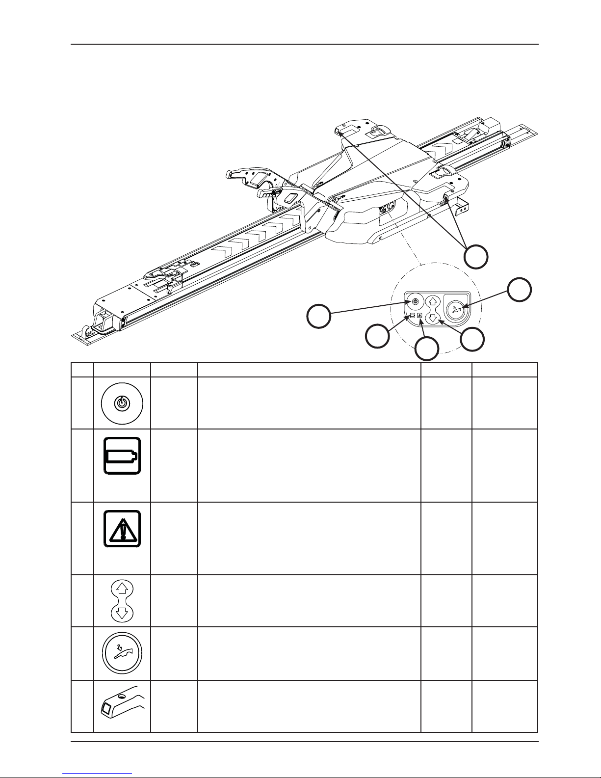
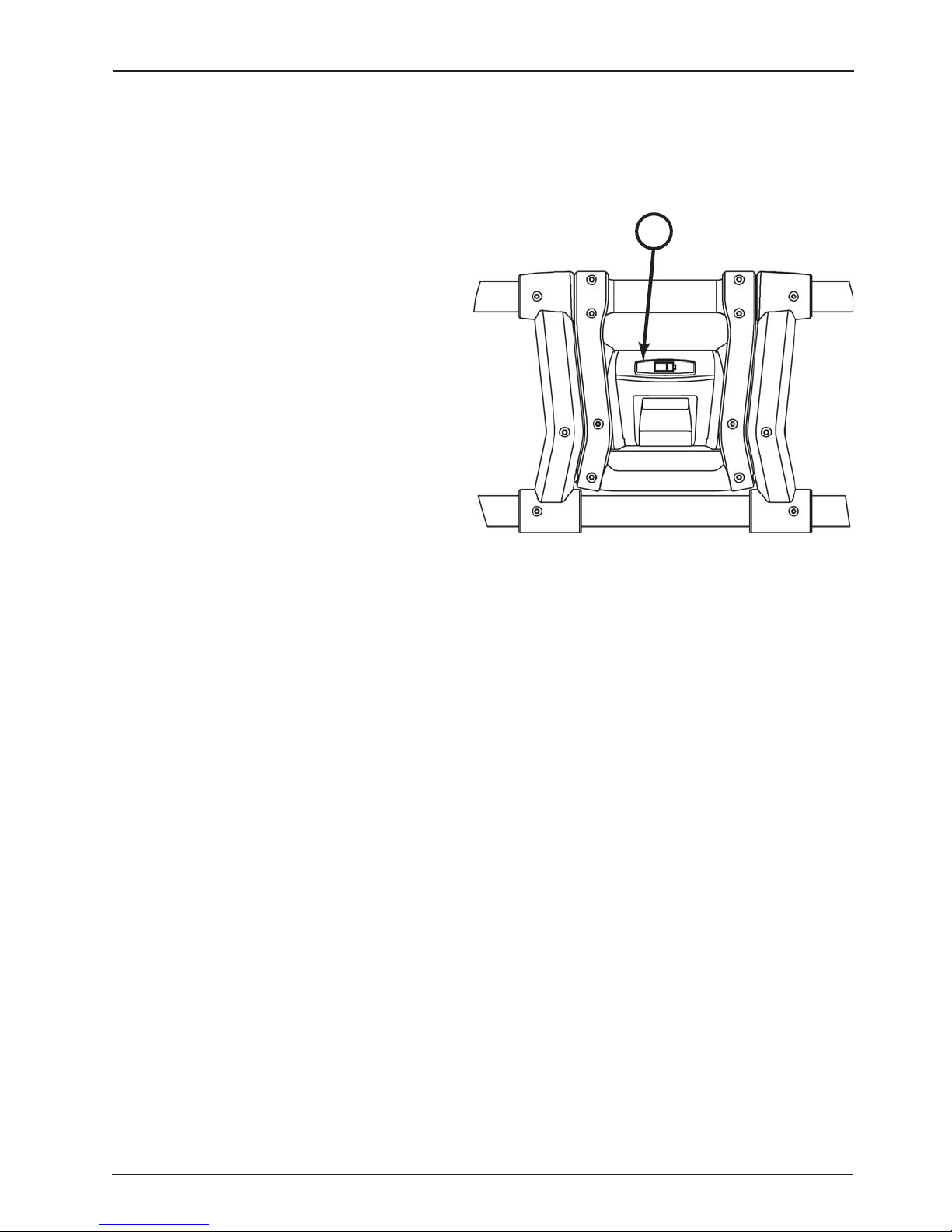
Power-LOAD LED indicators, located on the side Power-LOAD control panel and at the head end of Power-LOAD,
display Power-LOAD battery and system status.
This figure and table highlight all Power-LOAD buttons and
LED indicators.
Note: If Power-LOAD will not be in
use for a week or more, press the
main power button (1) to turn the unit
off and avoid draining the battery.
Head End
6
Power-LOAD Control Panel
1
Foot End
2
4
3
Ref Icon/Button Name Description Type Location
1
2
3
4
5
Main
Power
Battery
Power
Error If LED is solid amber, there is a Power-LOAD error.
Up/Down
Manual
Release
Press to power the unit on or off.
Note: The battery power LED also illuminates to
indicate that the Power-LOAD system is on. If the
trolley battery is low, a flashing amber LED may appear.
If LED is solid green, the Power-LOAD system is on
and not charging.
If LED is flashing green, the battery is charging.
Note: The battery will only charge when the trolley
is locked at the head end of the vehicle patient
compartment.
Press the main power button twice to reset the unit.
If the LED remains solid amber, contact technical
support.
If LED is flashing amber, the Power-LOAD battery
power is low.
Press up (Ç) to raise the lifting arms to the highest
position.
Note: The cot legs do not retract.
Press down (È) to lower the lifting arms and cot.
Ensure that the cot base is extended before pressing.
Press to unload the cot in the event of a Power-LOAD
power failure. Continue holding the button until the
arms are clear of the cot.
Button Power-LOAD
Control Panel
LED Power-LOAD
Control Panel
LED Power-LOAD
Control Panel
Button Power-LOAD
Control Panel
Button Power-LOAD
Control Panel
5
6
www.stryker.com 6390-009-001 REV B 41
Head
End Lock
Indicator
If LEDs are solid green, the cot head end is locked into
Power-LOAD.
If LEDs are flashing red, the cot head end is not locked
into Power-LOAD.
LED Trolley
Head End
Return To Table of Contents
Page 3
User Controls and LED Indicators
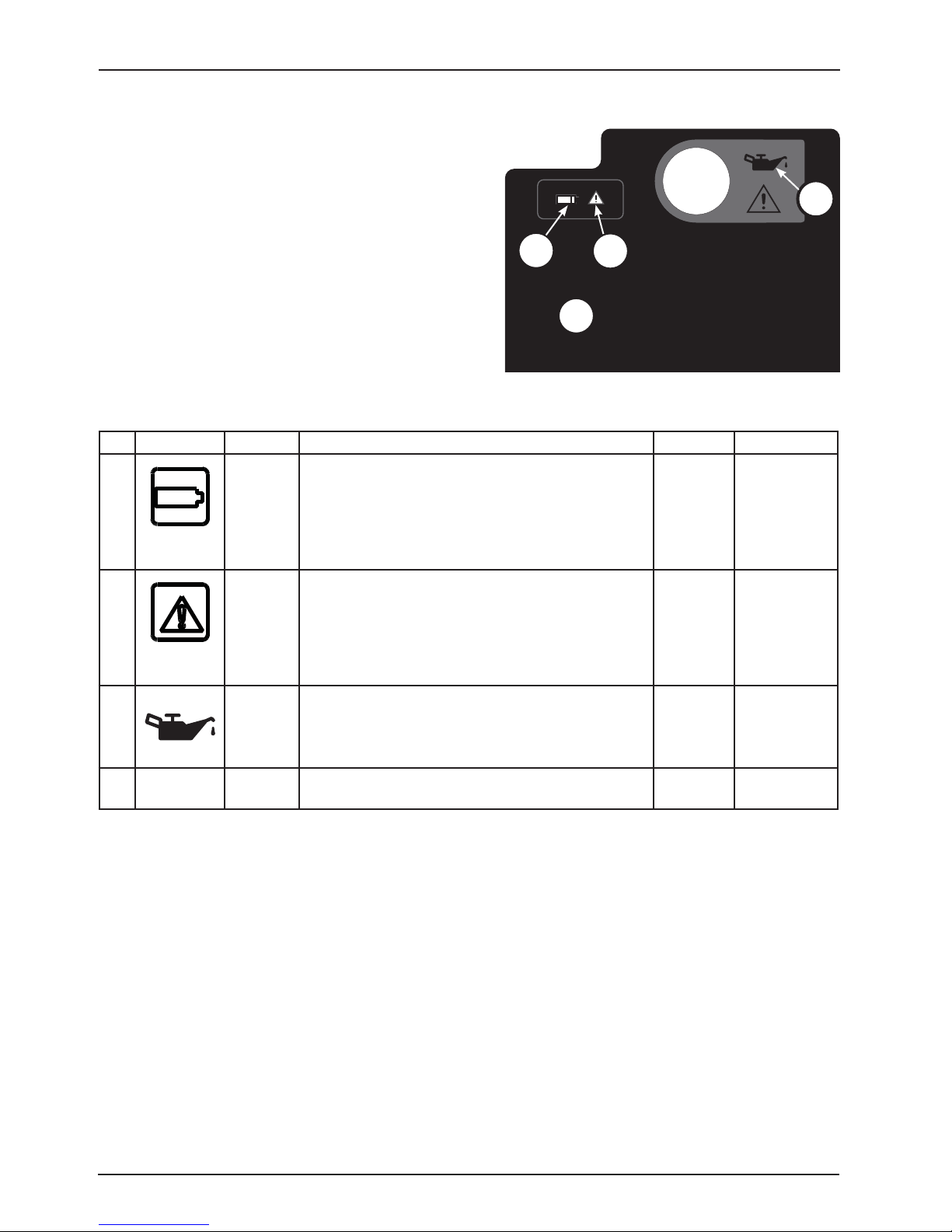
These Power-LOAD LED indicators are located at the head
end of the Power-LOAD trolley.
The oil reservoir location is shown for your reference.
9
7
8
10
Trolley Head End Label
Ref Icon/Button Name Description Type Location
7
8
9
Battery
Power
Error If LED is solid amber, there is a Power-LOAD error.
Oil
Reservoir
If LED is solid green, the Power-LOAD system is on
and not charging.
If LED is flashing green, the battery is charging.
Note: The battery will only charge when the trolley
is locked at the head end of the vehicle patient
compartment.
Press the main power button twice to reset the unit.
If the LED remains solid amber, contact technical
support.
If LED is flashing amber, the Power-LOAD battery
power is low.
Add Mobil Mercon® V Synthetic Blend Oil (6500001-293) here until full. To avoid the risk of a unit
malfunction or leak, do not overfill the reservoir with oil.
LED Trolley
Head End
LED Trolley
Head End
Not
Applicable
Trolley
Head End
10 Not
Applicable
Return To Table of Contents
42 6390-009-001 REV B www.stryker.com
USB Port Remove plate to access the USB port for input/output
diagnostics. Service only by qualified personnel.
Not
Applicable
Trolley
Head End
Page 4
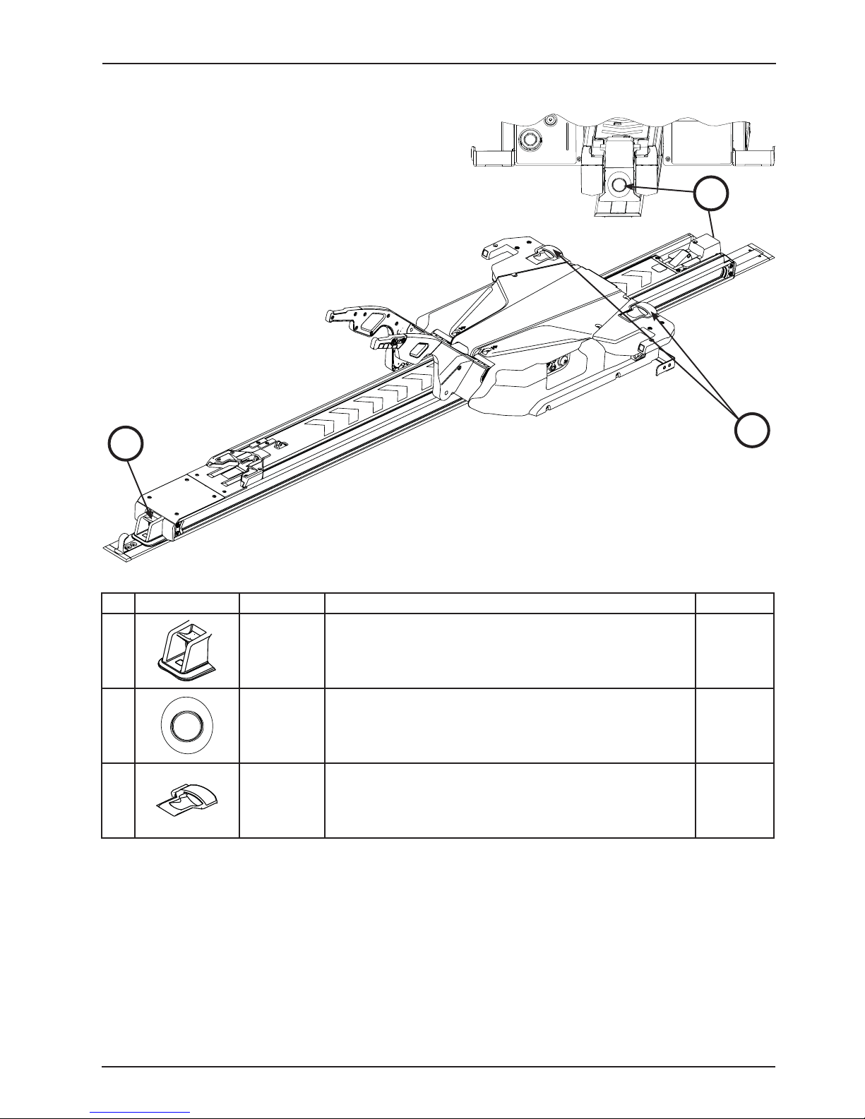
Manual User Controls
These three manual user controls allow you to release a cot
from Power-LOAD without any power:
Ǩɣ Release Lever
Ǩɣ Trolley Release Button
Ǩɣ Cot Release Handle
12
Head End
11
Foot End
Ref Manual Control Name Description Location
11 Release
Lever
12
13
Trolley
Release
Button
Cot Release
Handle
Press and hold to disengage the cot from the vehicle patient
compartment.
Press while raising the lifting arms to release and extend PowerLOAD from the vehicle patient compartment without a cot.
Then, pull the trolley out of the vehicle patient compartment.
Lift to unlock the cot from Power-LOAD when the cot base is
fully extended.
Foot End
Head End
Trolley
Head End
13
www.stryker.com 6390-009-001 REV B 43
Return To Table of Contents
Page 5
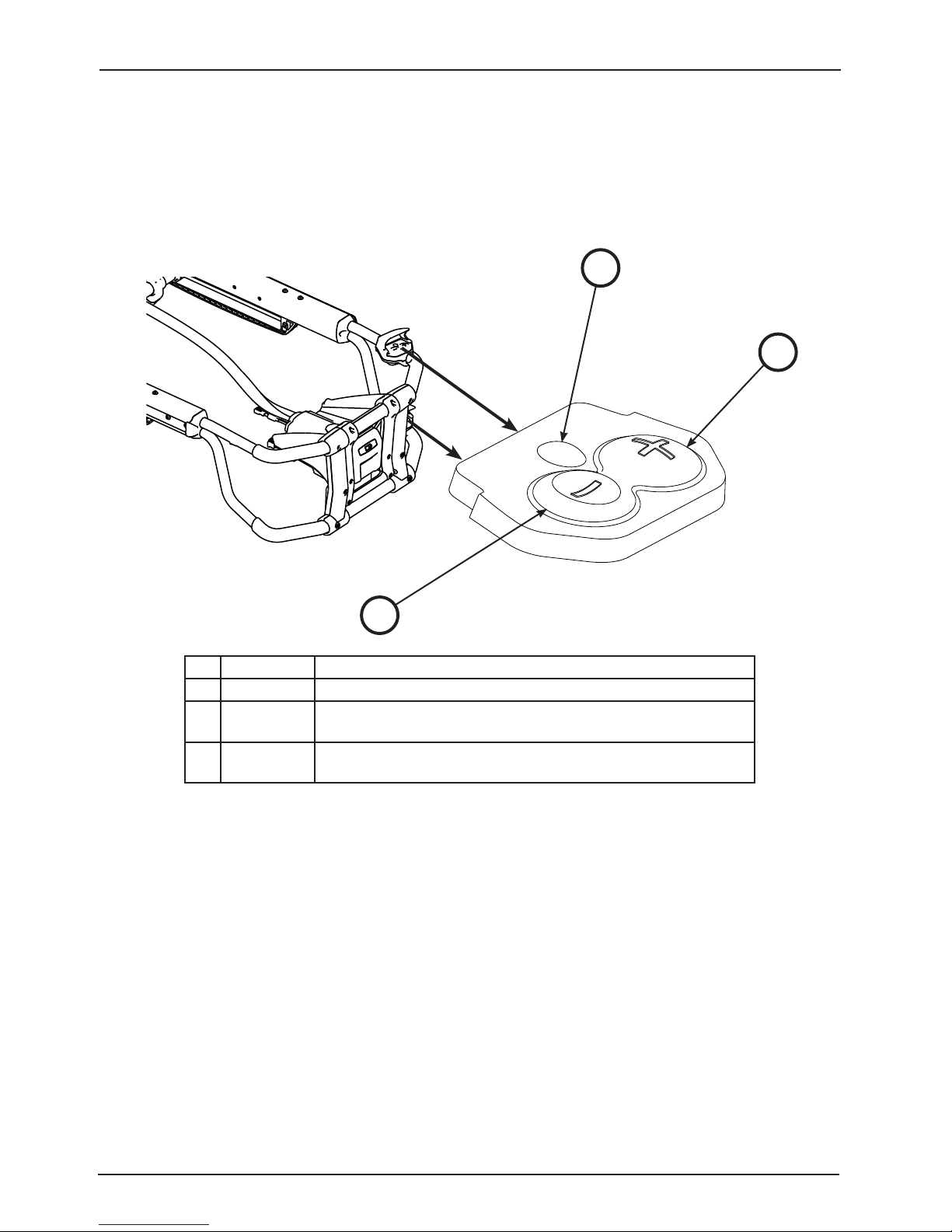
Power-PRO Cot User Controls
USING THE COT CONTROL SWITCHES
There are two cot control switches located on the Power-PRO cots (models 6500/6506 and 6510/6516). Press the
buttons on either of these switches to extend the cot, retract the cot, or release the cot from Power-LOAD.
This figure and table highlight the three buttons located on the cot control switch.
1
3
2
Ref Name Description
1 Release Press to unlock the cot from Power-LOAD.
2 Retract (-) Press and hold to fully retract the cot undercarriage until the cot is
supported.
3 Extend (+) Press and hold to fully extend the cot undercarriage until the cot
wheels are on the ground.
Return To Table of Contents
44 6390-009-001 REV B www.stryker.com
Page 6
Power-PRO Cot User Controls
CHECKING THE COT BATTERY POWER LEVEL
Power-LOAD automatically charges the Power-PRO SMRT™ Pak battery when the cot is locked into Power-LOAD in
the transport position (no cable or connectors required). The cot battery LED indicator momentarily flashes green to
signify that it is charging.
To check the battery power level, press the retract (–)
button (2) on the cot control switch to activate the cot
battery LED indicator (A) as shown in Figure 32.
The cot battery LED indicator is located at the PowerPRO foot end control enclosure (shown as a battery
symbol).
Ǩɣ The LED is solid green when the battery is fully
charged or has adequately charged battery
power.
Ǩɣ The LED flashes red when the battery needs to
be recharged or replaced.
Ǩɣ The LED is solid red to indicate a battery error.
See the SMRT Power System Operations/Maintenance
manual for additional SMRT Pak and SMRT Charger
information.
See the Power-PRO Operations/Maintenance manual
for additional cot battery information.
Notes:
Ǩɣ Automatic charging will only occur with SMRT Pak batteries.
Ǩɣ Only use Stryker-approved batteries with Power-LOAD.
A
Figure 32: Battery Power LED Indicator
www.stryker.com 6390-009-001 REV B 45
Return To Table of Contents
Page 7

Powered Operations Instructions
Locate this Powered Operation instruction label (6390-001-498) on the inside door panel or wall of the vehicle patient
compartment where visible to users.
POWERED OPERATIONS
Load Unload
1
2
3
1
2
CAPACITY
870
LE D B ehavior
Ready to
load cot
Cot is locked
in position
Between
z
z
z
positions or
in sleep mode
3
System on
Battery is
charging
4
4
Low battery
System Error
Use Manual
Operations
1 of 2
To unload Power-LOAD:
1. Press and hold the release lever at the foot end of the Power-LOAD system and pull to remove the cot from the
vehicle patient compartment.
2. Press and hold the extend (+) button on the cot control switch to extend the cot undercarriage to the set load height
with the cot wheels on the ground.
3. Press the red release button on the cot control switch to unlock the cot from Power-LOAD.
4. Raise the lifting arms and guide the trolley into the vehicle patient compartment until the arms are far enough in
to not interfere with the vehicle doors.
5. For additional unloading instructions, see “Unloading a Power-PRO Cot from a Vehicle (Model 6500/6506 &
6510/6516 with the Power-LOAD Option)” on
page 57.
To load Power-LOAD:
1. Raise the lifting arms to guide and pull the trolley out of the vehicle patient compartment.
2. Push the cot into Power-LOAD until the cot load wheel pins lock into position. Ensure that the cot is aligned with
the lifting arms when loading.
3. Press and hold the retract (–) button on the cot control switch to fully retract the cot undercarriage until the cot
is supported.
4. Push the cot into the vehicle patient compartment until the lifting arms lower and the cot locks into Power-LOAD.
5. Ensure that the cot is locked into Power-LOAD by firmly pulling on the foot end of the cot.
6. For additional unloading instructions, see “Loading a Power-PRO Cot into a Vehicle (Model 6500/6506 & 6510/6516
with the Power-LOAD Option)” on
See “User Controls and LED Indicators” on
page 55.
page 41 for button and LED locations and descriptions.
Note: If Power-LOAD will not be in use for a week or more, press the main power button to turn the unit off and avoid
draining the battery.
Return To Table of Contents
46 6390-009-001 REV B www.stryker.com
Page 8

Manual Operations Instructions
Locate this Manual Operation instruction label (6390-001-499) on the inside door panel or wall of the vehicle patient
compartment where visible to users.
MANUAL OPERATIONS
Load
Unload
WAR NING:
Improper usage of the Power-LOAD system or
any accessory can cause injury to the patient or
operator. Operate the Power-LOAD system and
accessories only as described in the manuals.
For Manual Operations, the operator must
support the foot end of the cot.
Other Controls
2 of 2
To load Power-LOAD:
1. Ensure that Power-LOAD is located at the head end of the vehicle patient compartment with the lifting arms down.
2. Push the cot into the vehicle patient compartment until the cot locks into Power-LOAD.
3. Ensure that the cot is locked into Power-LOAD by firmly pulling on the foot end of the cot.
4. For additional loading instructions, see “Loading a Cot into a Vehicle Manually (Power-LOAD Power Loss or
System Error)” on
page 61.
To unload Power-LOAD:
Press and hold the release lever at the foot end of the Power-LOAD system and pull to remove the cot from the vehicle
patient compartment. For additional unloading instructions, “Unloading a Cot from a Vehicle Manually” on
page 62.
Note: Without power, the lifting arms may not raise the cot. Operators must be ready to accept the entire weight of
the cot.
See “User Controls and LED Indicators” on
page 41 for button and LED locations and descriptions.
Note: If Power-LOAD will not be in use for a week or more, press the main power button to turn the unit off and avoid
draining the battery.
WARNING
Ǩɣ Improper usage of the Power-LOAD system or any accessory can cause injury to the patient or operator. Operate
the Power-LOAD system and accessories only as described in the manuals.
Ǩɣ For manual operations, the operator must support the foot end of the cot.
www.stryker.com 6390-009-001 REV B 47
Return To Table of Contents
Page 9

Operation Guide
OPERATING GUIDELINES
Ǩɣ Check Power-LOAD for proper functionality before starting each shift (the lifting arms should slightly raise the cot
as the cot is unlocked, check the battery power level, etc.). If the unit does not seem to be operating properly,
remove the vehicle from service to diagnose and repair Power-LOAD.
Ǩɣ Do not operate Power-LOAD with weights greater than 700 lb (318 kg), which includes patient weight and
accessories. The safe working load of Power-LOAD is 870 lb (395 kg), which includes the weight of the cot.
Ǩɣ Do not turn off the main power button during normal use as it will prevent battery charging.
Ǩɣ Do not drive the vehicle with the trolley in the mid position. This position does not lock and is not intended for
driving.
Ǩɣ Power-LOAD is only an assisting device. Operators are responsible for evaluating each situation to determine how
to distribute and lift the weight being transported. Always use both hands when handling the cot.
Ǩɣ When handling weights over 400 lb (181 kg), ensure there are enough operators to handle the forces required
for loading/unloading. To increase safety, users should attempt to perform loading/unloading on flat surfaces.
Ǩɣ Keep hands and extremities clear of the Power-LOAD trolley lifting arms and the cot base during powered loading
and unloading.
Ǩɣ Use caution when operating Power-LOAD in adverse weather conditions (for example, rain, ice, snow) to avoid
operator and/or patient injury.
Ǩɣ Operate Power-LOAD with the vehicle on a flat surface, if possible.
Ǩɣ If you are unable to unload an occupied cot from the vehicle patient compartment, use a backboard to unload the
patient.
Ǩɣ Stryker recommends periodic training (at least once per year) on manual backup procedures. See “Unloading
a Cot From a Vehicle Manually (Power-LOAD Power Loss or System Error)” on
a Vehicle Manually (Power-LOAD Power Loss or System Error)” on page 61, “Unloading a Cot from a Vehicle
Manually” on page 62 “Unloading a Cot from a Vehicle Manually” on page 62, “Loading a Cot into a Vehicle
Manually (Power-PRO Power Loss)” on page 64.
page 59, “Loading a Cot into
WARNING
Ǩɣ Improper usage of the Power-LOAD system or any accessory can cause injury to the patient or operator. Operate
the Power-LOAD system and accessories only as described in the manuals.
Ǩɣ Failure to ensure proper Power-LOAD functionality prior to use may result in patient and/or operator injury.
Ǩɣ Use caution while moving around in the vehicle patient compartment to avoid tripping on Power-LOAD.
Ǩɣ To avoid the risk of operator and/or patient injury, use caution when operating Power-LOAD in adverse weather
conditions (for example, rain, ice, snow).
Ǩɣ Entanglement in powered cot and/or Power-LOAD mechanisms can cause serious injury. Operate the cot and/or
Power-LOAD only when all persons are clear of the mechanisms.
Ǩɣ Practice loading and unloading the cot with Power-LOAD until operation of the product is fully understood. Improper
use can cause injury.
Ǩɣ Do not allow untrained personnel to assist in the operation of Power-LOAD. Untrained technicians/personnel can
cause injury to the patient or themselves.
Ǩɣ To reduce the risk of patient injury and/or equipment damage, do not drive the vehicle with the trolley in the mid
position. This position does not lock and is not intended for driving.
Ǩɣ Power-LOAD is only an assisting device. Operators are responsible for evaluating each situation to determine how
to distribute and lift the weight being transported. Always use both hands when handling the cot.
Ǩɣ When handling weights over 400 lb (181 kg), ensure there are enough operators to handle the forces required
for loading/unloading. To increase safety, users should attempt to perform loading/unloading on flat surfaces.
Ǩɣ Keep hands and extremities clear of the Power-LOAD trolley lifting arms and the cot base during powered loading
and unloading.
CAUTION
Possible fire hazard when used with oxygen administering equipment of other than nasal, mask or 1/2 bed length tent
type. Oxygen tent should not extend below mattress support level nor be used around Power-LOAD or a Power-LOAD
compatible cot.
Return To Table of Contents
48 6390-009-001 REV B www.stryker.com
Page 10

Operation Guide
CHECKING THE BATTERY POWER LEVEL
Ensure that the trolley power is turned on and check the battery power level on the Power-LOAD control panel (shown
as a battery symbol).
Ǩɣ The battery power LED is solid green when the Power-LOAD system is on and not charging.
Ǩɣ The battery power LED flashes green when the battery is charging.
Ǩɣ The error LED flashes amber when the battery is low.
To charge the battery, see “Charging the Battery”
.
WARNING
Ǩɣ Return damaged batteries to a service center for recycling. Do not dispose of the battery.
Ǩɣ To reduce the risk of electric shock, do not remove the battery when Power-LOAD in operation.
Ǩɣ Before servicing Power-LOAD, disconnect the vehicle battery, press the main power button to turn the unit off, and
then place the trolley into the loading position.
CHARGING THE BATTERY
Ensure that the battery is sufficiently charged for the Power-LOAD to operate properly. When fully discharged, the
battery requires approximately 10 hours to recharge. The batteries charge whenever the trolley is locked into the head
end of the vehicle patient compartment.
To charge the battery:
1. Raise the lifting arms and manually push the trolley into the head end of the vehicle patient compartment.
2. Lock the trolley at the head end of the vehicle patient compartment.
Note: The battery power LED flashes green when the battery is charging.
To check the battery power level, see “Checking the Battery Power Level”.
Note: If Power-LOAD will not be in use for a week or more, press the main power button to turn the unit off and avoid
draining the battery.
WARNING
Do not press the main power button to turn the unit off during normal use as it will prevent battery charging.
STORING POWER-LOAD
All batteries lose charge during storage or periods of inactivity. If Power-LOAD will not be in use for a week or more,
press the main power button to turn the unit off and avoid draining the battery.
SETTING THE COT LOAD HEIGHT
You must set the cot load height for the cot with the Power-LOAD option before placing the vehicle into service. For
a list of compatible cots, see “Vehicle Cot Compatibility Information” on
Manual for your cot for more information about how to set the appropriate cot height.
www.stryker.com 6390-009-001 REV B 49
page 14. See the Operations/Maintenance
Return To Table of Contents
Page 11
Operation Guide
USING A NON-UPGRADED X-FRAME COT FOR A MASS CASUALTY INCIDENT
Some non-compatible cots, including most X-frame cots, may be used in a mass casualty incident. The loading
and unloading operations are similar to the instructions for manual loading and unloading of a cot (see page 61),
however, a rail clamp assembly is used instead of a foot end cot lock. When loading a non-compatible cot, lock the
cot retaining post into the rail clamp assembly.
The mass casualty option contains a rail assembly for wall or floor mount. You should store this rail assembly in a
cabinet in case of emergency for quick attachment in the vehicle patient compartment.
WARNING
Ǩɣ To prevent the cot frame from coming out of the rail jaws, the space between the rail clamp and the rail stationary
jaw must never exceed 1 in (2.5 cm). To prevent the cot from coming out of the rail jaws and causing possible
injury to the patient or user, the rail clamp must not overlap the red adjustment limit label on the rail tube.
Ǩɣ The rail clamp fastener closes with a strong spring action. To avoid injury, do not use hand or fingers to press the
manual trolley release button when the rail jaws are open.
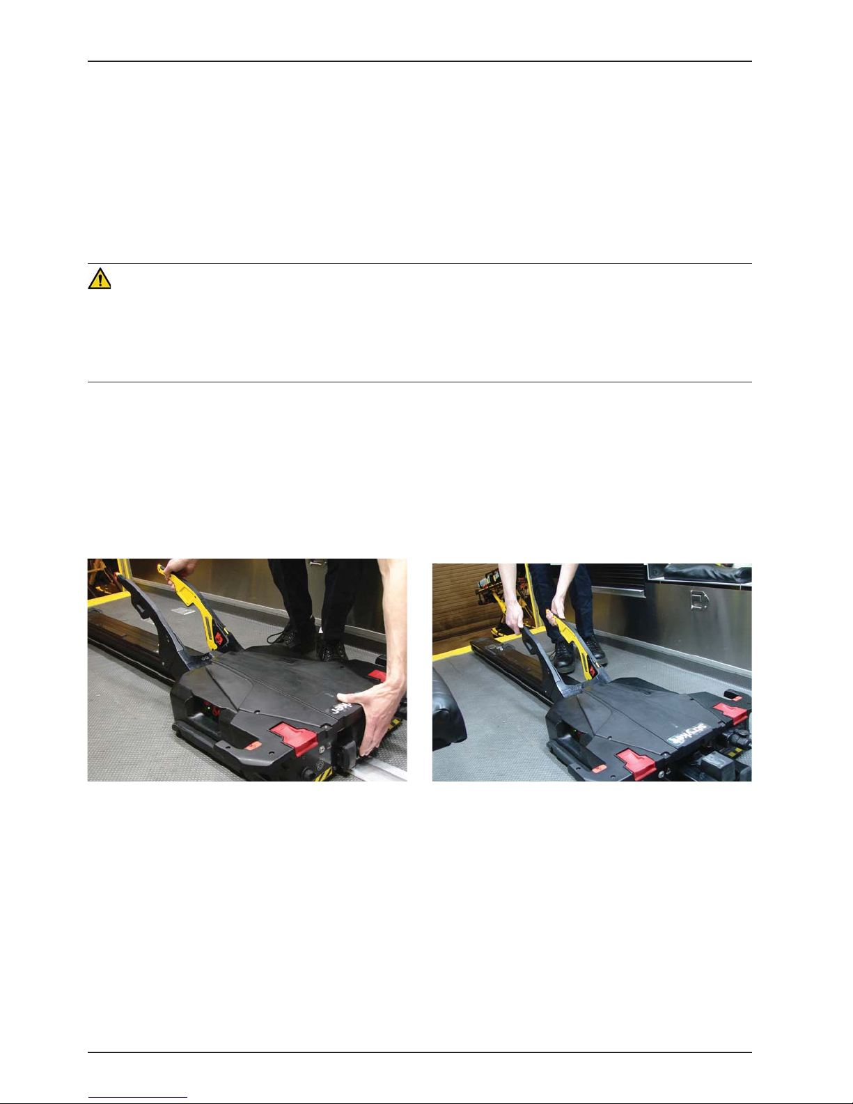
EXTENDING POWER-LOAD FROM THE VEHICLE WITHOUT A COT
To extend Power-LOAD from the vehicle patient compartment without a cot:
1. Walk to the head end of the Power-LOAD system.
2. While raising the lifting arms, press the manual trolley release button at the head end of the Power-LOAD system
as shown in Figure 33.
3. Pull the trolley out of the vehicle patient compartment as shown in Figure 34.
Figure 33: Press Manual Trolley Release Button Figure 34: Pull Trolley Out
Return To Table of Contents
50 6390-009-001 REV B www.stryker.com
Page 12

Operation Guide
LOADING A PERFORMANCE-PRO COT INTO A VEHICLE (MODEL 6085/6086 WITH THE POWER-LOAD
OPTION)
WARNING
Ǩɣ Loading and/or unloading an occupied cot into a vehicle requires a minimum of two (2) trained operators.
Ǩɣ Make sure that all occupants enter the vehicle patient compartment after the Power-LOAD compatible cot has been
loaded into the vehicle patient compartment.
1. Lift the vehicle bumper to the raised position (if equipped).
2. Raise the lifting arms to guide and pull the trolley out of the vehicle patient compartment as shown in Figure 35.
3. Raise the cot to the load position.
4. Push the cot into Power-LOAD until the cot load wheel pins lock into position as shown in Figure 36. Ensure that
the cot is aligned with the lifting arms when loading.
CAUTION
To avoid the risk of equipment damage, do not slam the cot into the trolley when loading.
Figure 35 Figure 36
5. Check the head end lock LED indicators to ensure that the cot is locked into Power-LOAD.
Ǩɣ If the LEDs are solid green, the cot head end is locked into Power-LOAD.
Ǩɣ If the LEDs are flashing red, the cot head end is not locked into Power-LOAD.
Return To Table of Contents
www.stryker.com 6390-009-001 REV B 51
Page 13

Operation Guide
LOADING A PERFORMANCE-PRO COT INTO A VEHICLE (MODEL 6085/6086 WITH THE POWER-LOAD
OPTION) (CONTINUED)
6. Press the up (Ç) button on the Power-LOAD control panel to raise the lifting arms to the highest position as shown
in Figure 37.
Note: The cot legs do not retract.
7. Operator 1 (Foot End) − Grasp the cot frame at the foot end. Squeeze and hold the cot manual release.
8. Operator 2 (Side) − Stabilize the cot by placing one hand on the outer rail. Grasp the base frame as shown
in Figure 38. After the foot end operator has lifted the cot and squeezed the cot manual release, retract the
undercarriage with one hand and hold it in place.
Figure 37 Figure 38
9. Operator 1 (Foot End) - Release the cot manual release to lock the undercarriage in the retracted position. Ensure
that the cot manual release is released. If it is not released, the cot will not lock at the foot end.
CAUTION
To avoid the risk of equipment damage, do not push the cot into the vehicle patient compartment until the cot base is
fully retracted.
10. Push the cot into the vehicle patient compartment until the lifting arms lower and the cot locks into Power-LOAD.
11. Ensure that the cot is locked into Power-LOAD by firmly pulling on the foot end of the cot.
Return To Table of Contents
52 6390-009-001 REV B www.stryker.com
Page 14
Operation Guide
UNLOADING A PERFORMANCE-PRO COT FROM A VEHICLE (MODEL 6085/6086 WITH THE POWERLOAD OPTION)
WARNING
Loading and/or unloading an occupied cot into a vehicle requires a minimum of two (2) trained operators.
1. Lift the vehicle bumper to the raised position (if equipped).
2. Press and hold the release lever at the foot end of the Power-LOAD system and pull to remove the cot from the
vehicle patient compartment.
WARNING
As the cot is unlocked for removal from the vehicle patient compartment, the Power-LOAD lifting arms will slightly raise
the cot. If the lifting arms do not raise the cot, then the operators must be ready to accept the entire weight of the cot
and patient to avoid injury.
3. Grasp the cot frame at the foot end to pull the cot out of the vehicle patient compartment.
Note: The head end lock LED indicators turn solid green only when the cot is ready to unload.
4. Operator 1 (Foot End) − Grasp the cot frame as shown
in Figure 39. Squeeze and hold the cot manual release.
5. Operator 2 (Side) − Grasp the base frame where
indicated in Figure 39, lift slightly, and lower the base
frame to its fully extended position. Verify that the cot
wheels are on the ground.
WARNING
When unloading the cot, ensure that the cot wheels are on
the ground before lowering the arms.
6. Operator 1 (Foot End) − Release the cot manual
release to lock the undercarriage into the extended
position.
Figure 39
www.stryker.com 6390-009-001 REV B 53
Return To Table of Contents
Page 15
Operation Guide
UNLOADING A PERFORMANCE-PRO COT FROM A VEHICLE (MODEL 6085/6086 WITH THE POWERLOAD OPTION) (CONTINUED)
7. Press the down (È) button on the Power-LOAD control panel to lower the lifting arms and cot as shown in Figure
40
8. Lift one of the two red manual cot release handles at the head end of the trolley to unlock the cot as shown in
Figure 41.
Figure 40 Figure 41
9. Raise the lifting arms and guide the trolley into the vehicle patient compartment until the arms are far enough in
to not interfere with the vehicle doors.
Return To Table of Contents
54 6390-009-001 REV B www.stryker.com
Page 16

Operation Guide
LOADING A POWER-PRO COT INTO A VEHICLE (MODEL 6500/6506 & 6510/6516 WITH THE POWERLOAD OPTION)
WARNING
Ǩɣ Loading and/or unloading an occupied cot into a vehicle requires a minimum of two (2) trained operators.
Ǩɣ Make sure that all occupants enter the vehicle patient compartment after the Power-LOAD compatible cot has been
loaded into the vehicle patient compartment.
1. Lift the vehicle bumper to the raised position (if equipped).
2. Raise the lifting arms to guide and pull the trolley out of the vehicle patient compartment as shown in Figure 42.
3. Press and hold the extend (+) button on the cot control switch to extend the cot undercarriage to the set load height
with the cot wheels on the ground. (Figure 43).
Figure 42 Figure 43
4. Push the cot into Power-LOAD until the cot load wheel
pins lock into position as shown in Figure 44. Ensure
that the cot is aligned with the lifting arms when loading.
CAUTION
To avoid the risk of equipment damage, do not slam the cot
into the trolley when loading.
5. Check the head end lock LED indicators to ensure that
the cot is locked into Power-LOAD.
Ǩɣ If the LEDs are solid green, the cot head end is
locked into Power-LOAD.
Ǩɣ If the LEDs are flashing red, the cot head end is
not locked into Power-LOAD.
Figure 44
www.stryker.com 6390-009-001 REV B 55
Return To Table of Contents
Page 17

Operation Guide
LOADING A POWER-PRO COT INTO A VEHICLE (MODEL 6500/6506 & 6510/6516 WITH THE POWERLOAD OPTION) (CONTINUED)
6. Press and hold the retract (–) button on the cot control
switch, as shown in Figure 45, to fully retract the cot
undercarriage until the cot is supported.
7. Push the cot into the vehicle patient compartment
until the lifting arms lower and the cot locks into
Power-LOAD.
8. Ensure that the cot is locked into Power-LOAD by firmly
pulling on the foot end of the cot.
Figure 45
Return To Table of Contents
56 6390-009-001 REV B www.stryker.com
Page 18

Operation Guide
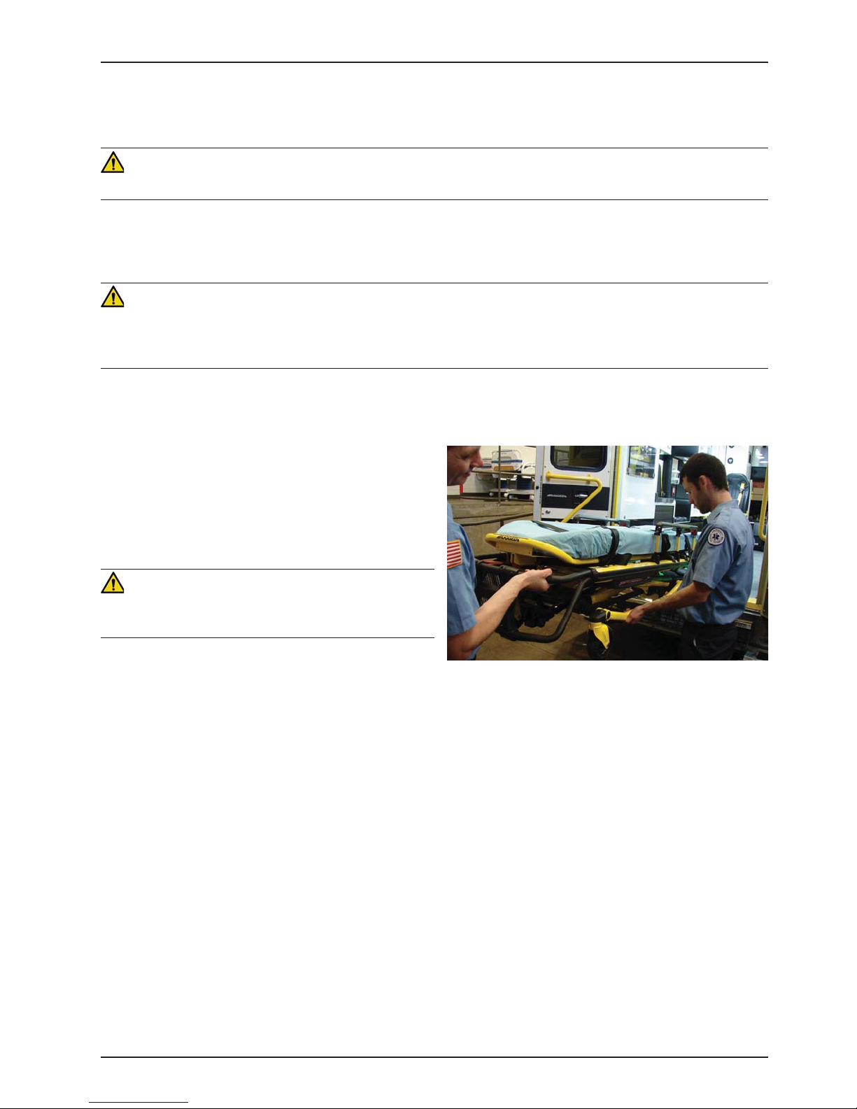
UNLOADING A POWER-PRO COT FROM A VEHICLE (MODEL 6500/6506 & 6510/6516 WITH THE
POWER-LOAD OPTION)
WARNING
Loading and/or unloading an occupied cot into a vehicle requires a minimum of two (2) trained operators.
1. Lift the vehicle bumper to the raised position (if equipped).
2. Press and hold the release lever at the foot end of the Power-LOAD system and pull to remove the cot from the
vehicle patient compartment as shown in Figure 46.
WARNING
As the cot is unlocked for removal from the vehicle patient compartment, the Power-LOAD lifting arms will slightly raise
the cot. If the lifting arms do not raise the cot, then the operators must be ready to accept the entire weight of the cot
and patient to avoid injury.
3. Grasp the cot frame at the foot end to pull the cot out of the vehicle patient compartment as shown in Figure 47.
Note: The head end lock LED indicators turn solid green only when the cot is ready to unload.
Figure 46 Figure 47
4. Press and hold the extend (+) button on the cot control switch to extend the cot undercarriage to the set load
height with the cot wheels on the ground.
5. Release the extend (+) button after the cot is no longer supported by the lifting arms. The lifting arms will continue
moving until they have fully lowered.
www.stryker.com 6390-009-001 REV B 57
Return To Table of Contents
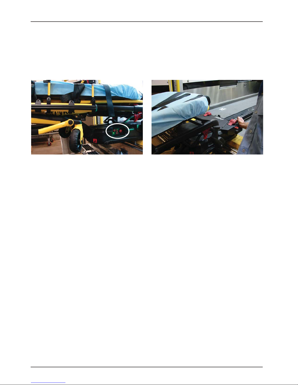
Page 19

Operation Guide
UNLOADING A POWER-PRO COT FROM A VEHICLE (MODEL 6500/6506 & 6510/6516 WITH THE
POWER-LOAD OPTION) (CONTINUED)
6. Press the red release button (Figure 48) on the cot control switch at the foot end of the cot or lift one of the two
red manual cot release handles at the head end of the trolley to unlock the cot (Figure 49).
Figure 48 Figure 49
7. Raise the lifting arms and guide the trolley into the vehicle patient compartment until the arms are far enough in
to not interfere with the vehicle doors.
Return To Table of Contents
58 6390 -009-001 REV B www.stryker.com
Page 20

Operation Guide
UNLOADING A COT FROM A VEHICLE MANUALLY (POWER-LOAD POWER LOSS OR SYSTEM ERROR)
WARNING
Ǩɣ Loading and/or unloading an occupied cot into a vehicle requires a minimum of two (2) trained operators.
Ǩɣ When unloading a cot from the vehicle patient compartment while Power-LOAD is experiencing a power loss or
system error, the operators must be ready to accept the entire weight of the cot and patient.
If Power-LOAD loses power or experiences a system error
after a cot has already been loaded, follow these steps to
unload the cot:
Note: The lifting arms will be in the up position.
1. Press and hold the release lever at the foot end of the
Power-LOAD system and pull to remove the cot from
the vehicle patient compartment as shown in Figure 50.
Note: The lifting arms may not raise the cot. Operators
must be ready to accept the entire weight of the cot.
2. Grasp the cot frame at the foot end to pull the cot out
of the vehicle patient compartment.
For models 6500/6506 and 6510/6516 with the PowerLOAD option:
Ǩɣ Operator 1 - Grasp the cot frame at the foot end. While supporting the weight of the cot, guide and pull the
cot out of the vehicle patient compartment until the safety bar engages the safety hook. Press and hold the
extend (+) button on the cot control switch to extend the cot undercarriage to the set load height with the cot
wheels on the ground.
Ǩɣ Operator 2 - Verify that the safety bar engages the safety hook and stabilize the cot during the unloading
operation by securely grasping the outer rail. Push the safety bar release lever forward to disengage the
safety bar from the safety hook in the vehicle patient compartment.
For models 6085/6086 with the Power-LOAD option:
Ǩɣ Operator 1 − Grasp the cot frame.
Ǩɣ Operator 2 − Grasp the base frame where indicated, lift slightly, and lower the base frame to its fully extended
position while Operator 1 squeezes and holds the cot manual release. Verify that the cot wheels are on the
ground.
Ǩɣ Operator 1 (Foot End) − Release the cot manual release to lock the undercarriage into the extended position.
Figure 50
WARNING
When unloading the cot, ensure that the cot wheels are on the ground before lowering the arms.
www.stryker.com 6390-009-001 REV B 59
Return To Table of Contents
 Loading...