

Page 1
PositionPRO® Patient Repositioning Support
Surface
Standalone with pendant or integrated with FL27 InTouch® CC
Model Beds
2920
Operations Manual
2016/10 G.2 2920-109-001 REV G
www.stryker.com
Page 2

sample text
Page 3

Symbols
~
Operating instructions/Consult instructions for use
General warning
Caution
Catalogue number
Serial number
Manufacturer
Safe working load
Alternating current
IPX4
Dangerous voltage
Protective earth ground
Protection from liquid splash
Type B equipment providing a particular degree of protection against electric shock, particularly
regarding allowable leakage current and reliability of the protective earth connection.
Class II Per Rule 9- PositionPRO is considered an active therapeutic device intended to be used
to administer or withdraw energy to or from the body.
Medical Equipment Recognized by Underwriters Laboratories LLC With Respect to Electric
Shock, Fire, and Mechanical Hazards only in accordance with UL 60601-1: 2003 and CAN/CSAC22.2 No. 601.1-M90 updates 1 and 2.
In accordance with European Directive 2012/19/EU on Waste Electrical and Electronic
Equipment, this symbol indicates that the product must not be disposed of as unsorted municipal
waste, but should be collected separately. Contact your local distributor for disposal information.
Wash by hand
Do not dry-clean
Allow to completely air dry
Do not tumble dry
Do not iron
www.stryker.com 2920-109-001 REV G
Page 4

Symbols
Chlorinated bleach
For US Patents see www.stryker.com/patents
Do not stack more than 1 high
2920-109-001 REV G www.stryker.com
Page 5

Table of Contents
Warning/Caution/Note Definition ..................................................................................................................3
Summary of safety precautions..............................................................................................................3
Introduction..............................................................................................................................................5
Product description.............................................................................................................................. 5
Indications for use ...............................................................................................................................5
Expected service life............................................................................................................................6
Contraindications ................................................................................................................................6
Specifications.....................................................................................................................................6
Contact information ............................................................................................................................. 7
Serial number location ......................................................................................................................... 7
Product illustration...............................................................................................................................8
Date of manufacture............................................................................................................................8
Installation ...............................................................................................................................................9
Operation .............................................................................................................................................. 13
Applying the linens ............................................................................................................................ 13
Positioning the patient ........................................................................................................................ 13
Activating CPR.................................................................................................................................. 14
Resetting CPR with the optional pendant control ...................................................................................... 14
Starting and stopping max inflate with the optional pendant control.............................................................. 15
Locking and unlocking the optional pendant control.................................................................................. 15
Adjusting firmness with the optional pendant control................................................................................. 16
Starting and stopping turn assist with the optional pendant control............................................................... 17
Alarming call maintenance with the optional pendant control ...................................................................... 19
Resetting CPR with the optional InTouch footboard .................................................................................. 19
Starting and stopping max inflate with the optional InTouch footboard .......................................................... 19
Locking and unlocking with the optional InTouch footboard ........................................................................ 19
Adjusting firmness with the optional InTouch footboard ............................................................................. 20
Starting and stopping turn assist with the optional InTouch footboard ........................................................... 21
Alarming call maintenance with the optional InTouch footboard .................................................................. 23
Transferring a patient to and from the support surface.............................................................................. 23
Transporting a patient ........................................................................................................................ 24
Managing incontinence and drainage .................................................................................................... 24
Cleaning................................................................................................................................................ 25
Cleaning the control box ..................................................................................................................... 25
Cleaning the pendant ......................................................................................................................... 25
Disinfecting............................................................................................................................................ 27
Preventive maintenance ........................................................................................................................... 28
Top cover replacement....................................................................................................................... 28
Fire barrier replacement ..................................................................................................................... 28
Quick reference replacement parts............................................................................................................. 30
EMC information ..................................................................................................................................... 31
Warranty ............................................................................................................................................... 35
Warranty exclusion and damage limitations ............................................................................................ 35
www.stryker.com 2920-109-001 REV G 1
Page 6

Table of Contents
To obtain parts and service ................................................................................................................. 35
Return authorization........................................................................................................................... 35
Damaged product.............................................................................................................................. 35
International warranty clause ............................................................................................................... 35
2 2920-109-001 REV G www.stryker.com
Page 7

Warning/Caution/Note Definition
The words WARNING, CAUTION, and NOTE carry special meanings and should be carefully reviewed.
WARNING
Alerts the reader about a situation which, if not avoided, could result in death or serious injury. It may also describe
potential serious adverse reactions and safety hazards.
CAUTION
Alerts the reader of a potentially hazardous situation which, if not avoided, may result in minor or moderate injury to the
user or patient or damage to the product or other property. This includes special care necessary for the safe and
effective use of the device and the care necessary to avoid damage to a device that may occur as a result of use or
misuse.
Note: Provides special information to make maintenance easier or important instructions clearer.
Summary of safety precautions
Carefully read and strictly follow the warnings and cautions listed on this page. Service only by qualified personnel.
WARNING
• Always make sure that the operator has access to the CPR straps.
• Do not stick needles into a support surface through the support surface cover. Holes may allow body fluids to enter
the inside (inner core) of the support surface and could cause cross-contamination, product damage, or product
malfunction.
• Do not use fitted sheets with this support surface.
• Always center the patient on the support surface before starting functions. Check the patient frequently for proper
positioning and to make sure that the support surface maintains proper inflation.
• Always make sure that the tubing and wiring that is connected to the patient is long enough, stabilized, and secure
during Lateral Rotation or Turn Assist.
• Do not extubate or intubate patients during Lateral Rotation or Turn Assist. The rotation functions could interfere
with the performance of the ancillary devices.
• Always secure the support surface anchoring straps to the bed frame.
• Always raise the bed siderails before starting Turn Assist.
• Do not leave the patient unattended during Turn Assist.
• Do not exceed the safe working load of the bed frame when supporting both the patient and the support surface.
Excess weight could cause unpredictable safety and performance of this product.
• Always deflate the support surface before beginning CPR.
• Do not arm bed exit with Lateral Rotation or Turn Assist active. The patient motion and position that results from the
support surface may adversely affect bed exit system performance.
• Do not use dynamic mattress systems for stroke victims without a physician’s order.
• Do not turn a patient with unstable fractures, unstable spinal cord injuries, or those in skeletal traction.
• Always monitor the patient condition at regular intervals for patient safety.
• Do not immerse support surface or foot box in cleaning or disinfectant solutions. To avoid the risk of product
damage or patient injury.
• Do not allow fluid to pool on the support surface or foot box. Fluids can cause degradation of components and may
cause unpredictable safety and performance of this product.
www.stryker.com 2920-109-001 REV G 3
Page 8

Warning/Caution/Note Definition
Summary of safety precautions (Continued)
WARNING (CONTINUED)
• Always inspect support surface covers (top and bottom) for tears, punctures, excessive wear, and misaligned
zippers each time the covers are cleaned. If compromised, the support surface cover should be removed from
service immediately and replaced to prevent cross-contamination.
• Always perform preventative maintenance more frequently based on the usage level of the product. The life of the
support surface can be adversely affected by an increase in usage which may include more frequent cleaning and
disinfection.
• Always allow the control box to completely dry before you place the support surface on top of it.
• Always disinfect the support surface between patients, to avoid the risk of cross-contamination and infection.
• Always make sure that you wipe each product with clean water and thoroughly dry each product after cleaning.
Some cleaning agents are corrosive in nature and may cause damage to the product if you use them improperly. If
you do not properly rinse and dry the product, a corrosive residue may be left on the surface of the product that
could cause premature degradation of critical components. Failure to follow these cleaning instructions may void
your warranty.
• Always unplug the product power cord before cleaning or disinfecting to avoid the risk of shock.
CAUTION
• Improper usage of the product can cause injury to the patient or operator. Operate the product only as described in
this manual.
• Do not modify the product or any components of the product. Modifying the product can cause unpredictable
operation resulting in injury to patient or operator. Modifying the product also voids its warranty.
• Always lower the foot end section gently to avoid the risk of damage to the control box.
• Do not allow sharp objects to come into contact with the support surface that could puncture tear or cut the cover.
• Always secure all patient lines and tubing together before starting Turn Assist to prevent pulling, removal, or
breakage.
• Do not iron, dry-clean, or tumble dry the support surface covers.
• Do not power wash the support surface as this may cause malfunction and damage the product.
• Always make sure that the support surface cover is completely dry before storing, adding linens or placing a patient
on the surface. Drying the product aids in preventing the performance of the product from being impaired.
• Do not over expose the covers to higher concentration disinfectant solutions as these may degrade the covers.
• Do not use accelerated hydrogen peroxides or quaternaries that contain glycol ethers as they may damage the
cover.
4 2920-109-001 REV G www.stryker.com
Page 9

Introduction
This manual assists you with the operation or maintenance of your Stryker product. Read this manual before operating
or maintaining this product. Set methods and procedures to educate and train your staff on the safe operation or
maintenance of this product.
CAUTION
• Improper usage of the product can cause injury to the patient or operator. Operate the product only as described in
this manual.
• Do not modify the product or any components of the product. Modifying the product can cause unpredictable
operation resulting in injury to patient or operator. Modifying the product also voids its warranty.
Notes
• This manual is a permanent part of the product and should remain with the product even if the product is sold.
• Stryker continually seeks advancements in product design and quality. This manual contains the most current
product information available at the time of printing. There may be minor discrepancies between your product and
this manual. If you have any questions, contact Stryker Customer Service or Technical Support at 1-800-327-0770.
Product description
PositionPRO® is a powered pressure relief support surface with low air loss (LAL) intended for medical purposes.
PositionPRO consists of multiple air cells filled and emptied by an integrated control unit to provide changes in the
distribution of body weight for pressure relief. PositionPRO offers turn assist. See the specifications page for
compatible frames.
Indications for use
PositionPRO is intended to assist in the prevention and treatment of pressure injures (including stages 1,2,3,4,
unstageable injury, and deep tissue injury) that are associated with immobile, critically ill, injured or hospitalized human
patients.
Use PositionPRO with a mattress cover at all times. The support surface is intended to support a patient’s full body.
PositionPRO is for patient use in acute care settings, which includes critical care, step down, progressive care,
med/surg, sub acute care, and post anesthesia care unit (PACU). The patient is under the care of a physician. The
typical operator is a healthcare professional. PositionPRO is not suitable for use in the presence of a flammable
anesthetic mixture with air or with oxygen or nitrous oxide.
PositionPRO is not intended to:
• support a patient in a prone position
• be used in a home health position
• be used as a sterile product
• include a measuring function
PositionPRO is not recommended for patients with the following conditions:
• unstable fractures
• skeletal traction
• agitated patients
• severe hemoptysis
• for whom a head-down position is contraindicated, such as a head injury
• bleeding disorders
• rib fractures / fractures
• predisposed to pathological fractures
www.stryker.com 2920-109-001 REV G 5
Page 10

Introduction
Indications for use (Continued)
• for whom the techniques increased dyspnea or wheezing
• who are hemodynamically unstable
Expected service life
PositionPRO has a five year expected service life under normal use, conditions, and with appropriate periodic
maintenance.
Contraindications
Patients with spinal cord injuries
Specifications
Model Pendant 2920-100-000
Integrated 2920-500-000
Dimensions Mattress 35” x 84” x 7” 88.9 cm x 213.4 cm x 17.8
Weight
Safe working load
Power cord
Over current protection 2 fuses 5 x 20 mm, 5 AMP Slo-Blo, 250 VAC
Output flow rate 12.5 LPM (0.4 SCFM) minimum @ 30mmHg
Current leakage
Classification Class 1 Grounded Equipment
Complete system
Mattress 29 lb 13.1 kg
Pendant 1 lb 0.45 kg
Pump Box 33 lb 15 kg
Stationary
Default 22 mmHg, optimal
pressure relief
Turn Assist 300 lb 136.1 kg
15 foot, 16 AWG cord with hospital grade plug for use with wall outlet
4 foot, 16 AWG cord with hospital grade plug for use with accessory outlet
120VAC; 50-60Hz, 1AMP; Two 250V, 5A Fuses
300 uA Maximum
Class 2, FDA and Health Canada
Continuous operation- Not suitable for use in the presence of flammable anesthetic
mixture with air or with oxygen or nitrous oxide. Suitable for continuous duty.
Medical equipment: Classified with respect to electric shock, mechanical hazards only,
in accordance with UL60601-1 CAN/CSA C22.2 No. 601.1.-M90.
Electromagnetic compatibility, meets EN 60601-1-2, 2001 (CISPR II classified as Class
A, Group 1 ISM equipment)
DH29201005 with Dartex Cover
DH29201015 with Nylon Cover
DH29201010 with Dartex Cover
DH29201020 with Nylon Cover
cm
63 lb 28.6 kg
500 lb 226.8 kg
200 lb 90.7 kg
6 2920-109-001 REV G www.stryker.com
Page 11
Specifications (Continued)
104°F
(40°C)
50°F
(10°C)
158 °F
(70 °C)
-40°F
(-40°C)
A
Introduction
Flammability standards
USA 16 CFR 1632, USA 16 CFR 1633, CALTB 129, Boston BFD IX-11
Method 27.7-1979 of CAN 2-4.2 M77
Compatible frames 84” x 35” flat deck frames GoBed II®, Secure 3®, InTouch®, and Epic II®
Stryker reserves the right to change specifications without notice.
Environmental conditions
Operation Storage and transportation
Temperature
Contact information
Contact Stryker Customer Service or Technical Support at: 1-800-327-0770.
Stryker Medical
3800 E. Centre Avenue
Portage, MI 49002
USA
To view your operations or maintenance manual online, see https://techweb.stryker.com/.
Have the serial number (A) of your Stryker product available when calling Stryker Customer Service or Technical
Support. Include the serial number in all written communication.
Serial number location
www.stryker.com 2920-109-001 REV G 7
Page 12
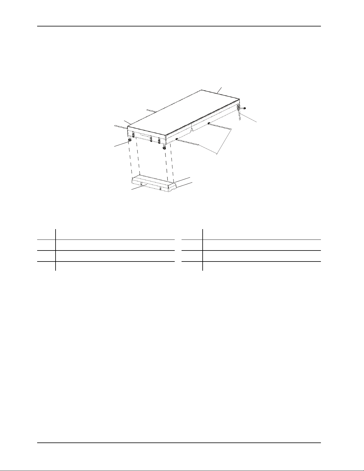
Product illustration
A
B
C
D
E
F
G
H
Introduction
Figure 1: Product illustration
A
B D rings F Head end
C
D Foot end H Power cord
CPR straps
Foot box
E Handles
G
Integration cable
Date of manufacture
The year of manufacture is the first four digits of the serial number.
8 2920-109-001 REV G www.stryker.com
Page 13

Installation
This section explains how to install the support surface and the control box. The support surface is either equipped with
a standalone pendant control option or integrated with InTouch FL27 Critical Care Bed option. The differences are
noted in the appropriate installation steps.
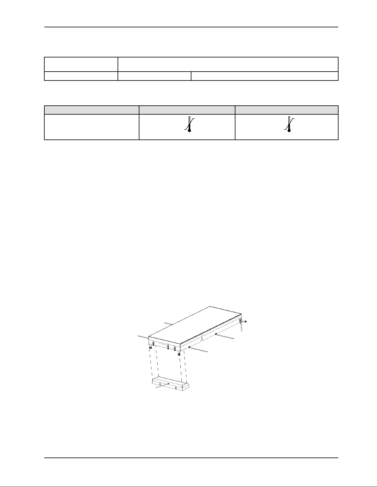
1. Position the support surface onto the bed.
2. Flip the foot section toward the head end.
3. Turn the control box upside down and place the control box into the opening in the foot section of the support
surface (Figure 2 on page 9).
Figure 2: Insert the foot box
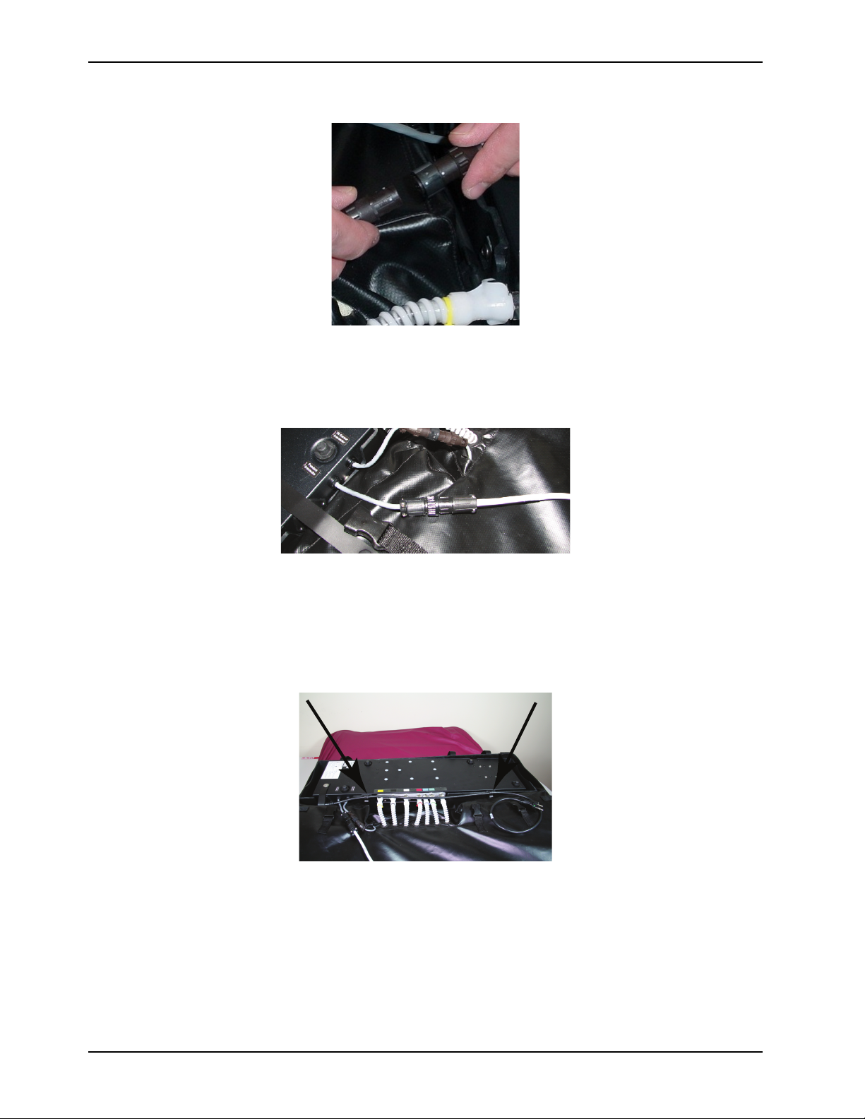
4. Match the outer transparent tubes colors to the manifold colors and connect them (Figure 3 on page 9) (Green,
Blue, Red, White, Black Yellow).
Figure 3: Connect tubes by color
5. Connect the tilt sensor cables.
a. Align the white dots on the tilt sensor cable connectors.
b. Twist the tilt sensor cables clockwise to fasten (Figure 4 on page 10).
www.stryker.com 2920-109-001 REV G 9
Page 14
Installation
Figure 4: Connect the tilt sensor cables
6. Connect the pendant cable (Figure 5 on page 10).
Note: The pendant cable for the InTouch FL27 bed is QDF27-1534.
Figure 5: Connect the pendant cable
7. Connect the power cord (4 in. or 15 in.) and turn the switch to the ON or 1 position.
Note: The switch is under the power cord.
8. Fasten the straps over the power cord.
9. Install the power cord in the two retaining clips (Figure 6 on page 10).
Figure 6: Retaining clips
10. Fasten the three retaining straps.
10 2920-109-001 REV G www.stryker.com
Page 15

Installation
11. Carefully rotate the foot end control box and support surface into the flat position (Figure 7 on page 11).
CAUTION
Always lower the foot end section gently to avoid the risk of damage to the control box.
Figure 7: Installation complete and ready to flip
12. Fasten all four of the retaining straps to secure the support surface to the bed frame (Installation on page 9Figure 9
on page 11).
Figure 8: Strap locations
Figure 9: Fasten the retaining straps
13. Install the clip for the pendant standalone optional control in one of the two locations listed below (Figure 10 on
page 11) and (Figure 11 on page 12).
a. Siderails
Figure 10: Pendant on siderails
b. Footboard
www.stryker.com 2920-109-001 REV G 11
Page 16

Installation
Figure 11: Pendant on footboard
Note: Always plug the hospital grade three-prong plug into a properly grounded receptacle to protect against
shock hazard. Grounding reliability can be achieved only when a hospital grade receptacle is used.
14. Connect the power cord to the power source.
15. Calibrate the bed following the procedures in the InTouch maintenance manual.
12 2920-109-001 REV G www.stryker.com
Page 17
Operation
Applying the linens
WARNING
• Always make sure that the operator has access to the CPR straps.
• Do not stick needles into a support surface through the support surface cover. Holes may allow body fluids to enter
the inside (inner core) of the support surface and could cause cross-contamination, product damage, or product
malfunction.
• Do not use fitted sheets with this support surface.
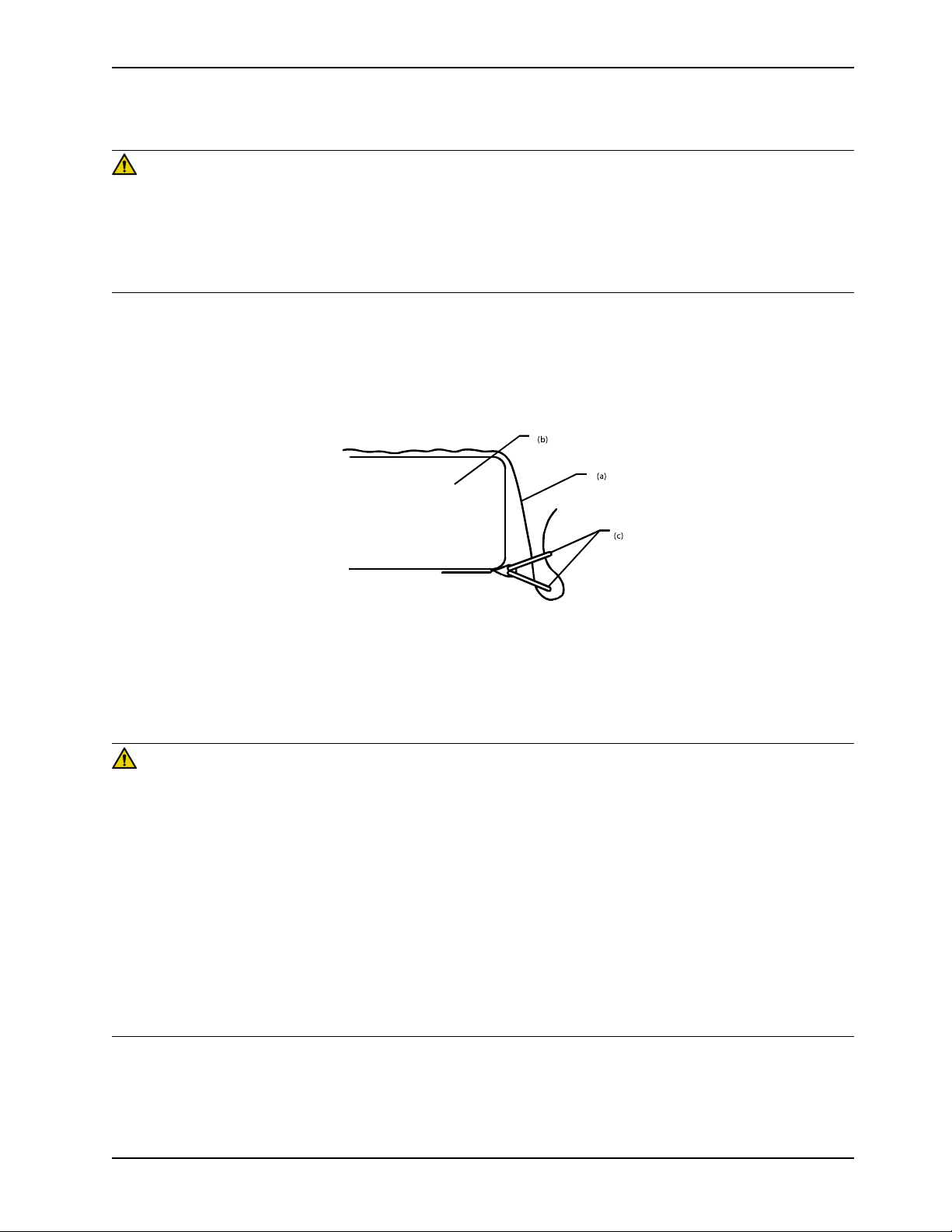
To apply the linens:
1. Apply the linens using the “D” rings for the flat sheet.
2. Thread the four linen corners through the “D” rings (c) attached to the support that are surface to secure the linens
(a) to the mattress (b).
Figure 12: Apply linens
Note: Do not pull the linens tight. Keep the linens loose and as smooth as possible on top of the support surface to
effectively use the Turn Assist and Lateral Rotation functions.
Positioning the patient
WARNING
• Always center the patient on the support surface before starting functions. Check the patient frequently for proper
positioning and to make sure that the support surface maintains proper inflation.
• Always make sure that the tubing and wiring that is connected to the patient is long enough, stabilized, and secure
during Lateral Rotation or Turn Assist.
• Do not extubate or intubate patients during Lateral Rotation or Turn Assist. The rotation functions could interfere
with the performance of the ancillary devices.
• Always secure the support surface anchoring straps to the bed frame.
• Always raise the bed siderails before starting Turn Assist.
• Do not leave the patient unattended during Turn Assist.
• Do not exceed the safe working load of the bed frame when supporting both the patient and the support surface.
Excess weight could cause unpredictable safety and performance of this product.
• Always deflate the support surface before beginning CPR.
www.stryker.com 2920-109-001 REV G 13
Page 18

Operation
Positioning the patient (Continued)
CAUTION
• Do not allow sharp objects to come into contact with the support surface that could puncture tear or cut the cover.
To position the patient:
1. Place the patient in the center of the support surface, aligning the patient’s head toward the head board.
2. Check the patient frequently during Turn Assist and Lateral Rotation for proper positioning and support surface
inflation.
Activating CPR
When CPR is activated, the manifold bladder deflates, the pump is off and all of the valves are energized. CPR
activation is detected by a fast drop of pressure in a short period of time.
WARNING
Always make sure that the operator has access to the CPR straps.
Pull the red CPR strap (Figure 13 on page 14) that is located on the left and right side of the head end of the mattress.
You can activate one or either of the straps.
Note: The CPR visual alarm LED turns red. The CPR alarm LED continues to flash to indicate that a hazardous situation
has been detected. The CPR alarm LED will continue to flash until you reset the alarm.
Figure 13: CPR Strap
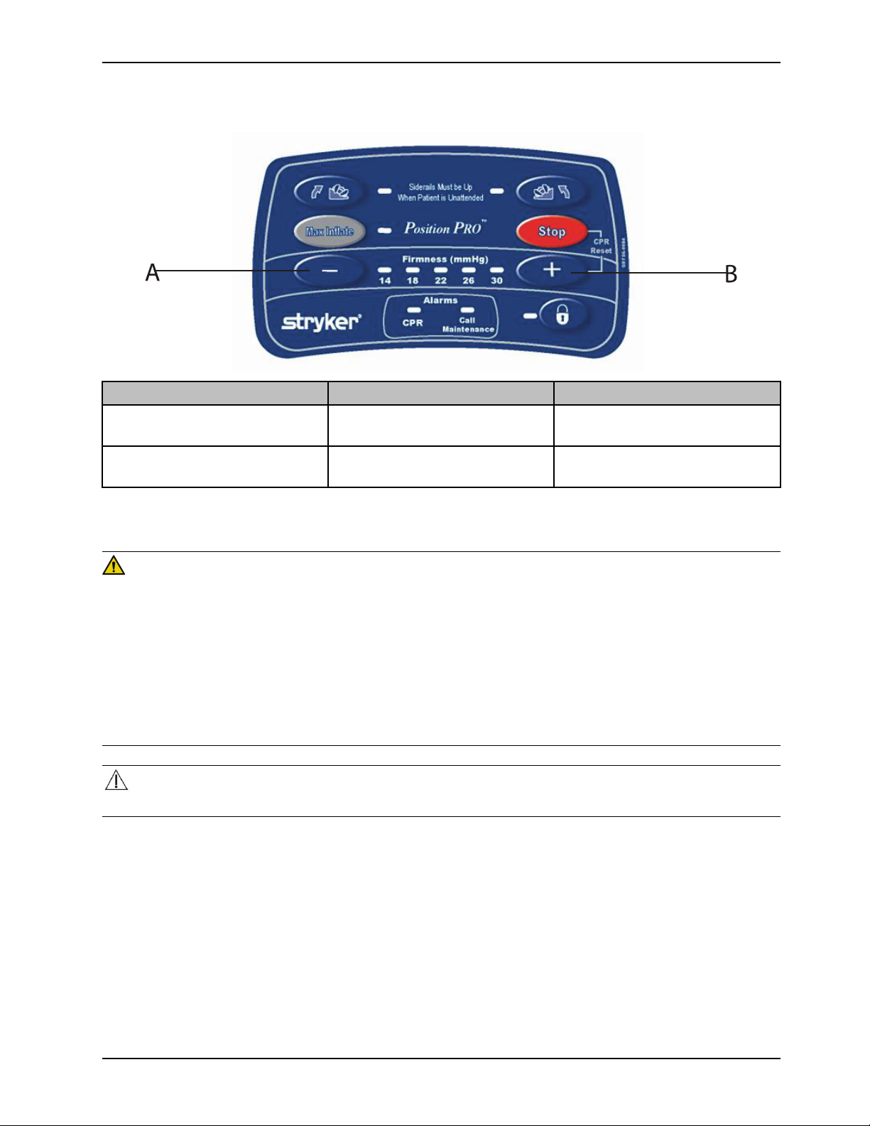
Resetting CPR with the optional pendant control
When you activate the CPR, the pendant CPR LED starts flashing red without an audible alert.
To reset the CPR:
1. Reinsert the red CPR straps by pulling down on the strap.
2. Press the Stop button and the Increase Firmness (+) button simultaneously to reset the CPR alarm. The support
surface will begin to reinflate.
14 2920-109-001 REV G www.stryker.com
Page 19

Operation
A
Resetting CPR with the optional pendant control (Continued)
Button Name Function
A
Stop and Firmness Increase (+)
Press both buttons at the same time
to reset the CPR.
Starting and stopping max inflate with the optional pendant control
To start Max Inflate:
Press the Max Inflate button to inflate the air bladders to the maximum level to aid in patient boosts and patient
transfers.
To stop Max Inflate:
Press the Max Inflate button to stop inflation.
Note: If Max Inflate has been on longer than 30 minutes, the alarm will sound, and the support surface will return to the
default firmness setting.
Locking and unlocking the optional pendant control
To Lock:
Press the Lock button to prevent options from being selected on the pendant after you have activated the functions.
To Unlock:
Press the Unlock button to allow the selection of options.
Note: When selected, the lock icon LED illuminates red.
www.stryker.com 2920-109-001 REV G 15
Page 20

Operation
A
B
C
Locking and unlocking the optional pendant control (Continued)
Button Name Function
A Max Inflate
Inflates the support surface to
maximum pressure (60 mmHg)
B
C
Stop
Lock Out / Unlock
Press once to return to previous
firmness setting
Press to lock all pendant functions
Press again to unlock all pendant
functions.
Adjusting firmness with the optional pendant control
You can adjust the support surface firmness settings for patient comfort. The product has five levels of firmness
settings that range from 14 mmHg to 30 mmHg. The default of 22 mmHg provides optimal pressure relief for patients up
to 200 lb. For average sized patients, 18-22mmHg is recommended.
Notes
• For larger patients, higher settings are recommended.
The increase firmness (+) and decrease firmness (-) buttons are inactive when Turn Assist or Max Inflate is active.
16 2920-109-001 REV G www.stryker.com
Page 21
Operation
Adjusting firmness with the optional pendant control (Continued)
Button Name Function
A Increase Firmness (+)
Increases the firmness level of the
support surface
B Decrease Firmness (-)
Decreases the firmness level of the
support surface
Starting and stopping turn assist with the optional pendant control
WARNING
• Do not arm bed exit with Lateral Rotation or Turn Assist active. The patient motion and position that results from the
support surface may adversely affect bed exit system performance.
• Always raise the bed siderails before starting Turn Assist, to avoid the risk of patient fall.
• Do not use dynamic mattress systems for stroke victims without a physician’s order.
• Do not turn a patient with unstable fractures, unstable spinal cord injuries, or those in skeletal traction.
• Do not extubate or intubate patients during Lateral Rotation or Turn Assist. The rotation functions could cause
interference with the performance of the ancillary devices.
• Do not leave the patient unattended during Turn Assist.
CAUTION
Always secure all patient lines and tubing together before starting Turn Assist to prevent pulling, removal, or breakage.
To prepare for Turn Assist:
1. Secure the patient lines, tubing, and power cords.
2. Center the patient on the support surface.
www.stryker.com 2920-109-001 REV G 17
Page 22

Operation
A
B
C
Starting and stopping turn assist with the optional pendant control (Continued)
3. Raise all the siderails on the bed.
Button Name Function
A Turn Assist Left
B
C
Turn Assist Right
Stop Turn Assist
Assists in turning the patient to the
left
Assists in turning the patient to the
right
• Press the Stop button after to
pause Turn Assist in any position.
• Press the Stop button twice to
deactivate Turn Assist in any
position.
• Press the Turn Assist Left button
or the Turn Assist Right button to
continue.
Notes
• PositionPRO can turn a 300 lb patient up to 40°.
• You can use the Turn Assist therapy with a timer so therapy can last up to 120 minutes without the need to
calculate the time the patient has been receiving this therapy.
• When patient is unattended, the warning illuminates when you activate the Left or Right Turn Assist function and
you have not raised the siderails.
• Right and left locations are from the perspective of the patient.
• Turn Assist Right or Left LEDs illuminate green when activated and remain illuminated after the function is complete.
• Turn Assist Right and Left LEDs blink when in process.
• Turn Assist will hold in a turned position for 2 hours if the Stop button is not pressed twice; after 2 hours have
passed, the support surface will return to flat.
18 2920-109-001 REV G www.stryker.com
Page 23

Operation
A
Alarming call maintenance with the optional pendant control
The alarm conditions Call Maintenance LED illuminates red and flashes to indicate when a hazardous situation has been
detected. Review the Error Alarms section and call appropriate technical support personnel.
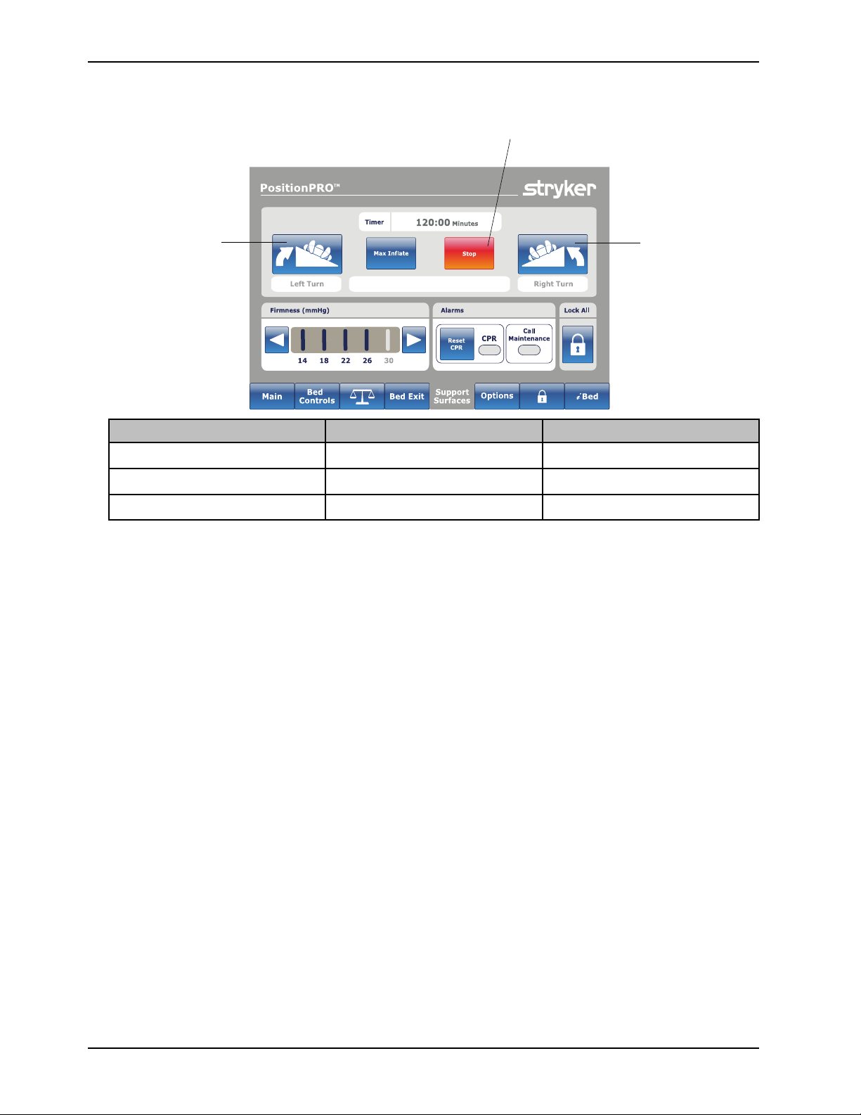
Resetting CPR with the optional InTouch footboard
To reset CPR:
Reinsert the red CPR straps by pulling down on the strap.
Button Name Function
A
Reset CPR Tap to reset the CPR alarm
Starting and stopping max inflate with the optional InTouch footboard
To start Max Inflate:
Tap Max Inflate to inflate the air bladders to the maximum level to aid in patient boosts and patient transfers.
To stop Max Inflate:
Tap Max Inflate to stop the inflation.
Note:
If Max Inflate has been on longer than 30 minutes, the alarm will sound, and the support surface will return to the default
firmness setting.
Locking and unlocking with the optional InTouch footboard
To Lock:
Tap Lock to prevent options from being selected on the InTouch footboard after you have activated the functions.
To Unlock:
Tap Unlock to allow the selection of options.
Note: When selected, the lock icon LED illuminates red.
www.stryker.com 2920-109-001 REV G 19
Page 24

Operation
A
B
C
Locking and unlocking with the optional InTouch footboard (Continued)
Button Name Function
A Max Inflate
Tap to inflate the support surface to
maximum pressure (60 mmHg).
B
C
Stop
Lock Out / Unlock
Tap once to return to previous
firmness setting.
Tap to lock all pendant functions.
Tap again to unlock all pendant
functions.
Adjusting firmness with the optional InTouch footboard
The support surface firmness settings may be adjusted for patient comfort requirements. The product has five levels of
firmness settings that range from 14 mmHg to 30 mmHg. The default of 22 mmHg will provide optimal pressure relief for
patients up to 200 lb. For average sized patients, 18-22mmHg is recommended.
Notes
• For larger patients, higher settings are recommended.
• Firmness increase and decrease are inactive when Turn Assist and Max Inflate are active.
20 2920-109-001 REV G www.stryker.com
Page 25

Operation
A
B
Adjusting firmness with the optional InTouch footboard (Continued)
Button Name Function
A Firmness Increase
Increases the firmness level of the
support surface
B Firmness Decrease
Decreases the firmness level of the
support surface
Starting and stopping turn assist with the optional InTouch footboard
WARNING
• Always raise the bed siderails before beginning Turn Assist, to avoid the risk of patient fall.
• Do not use dynamic mattress systems for stroke victims without a physician’s order.
• Do not turn a patient with unstable fractures, unstable spinal cord injuries, or those in skeletal traction.
• Do not extubate or intubate patients during Lateral Rotation or Turn Assist. The rotation functions could cause
interference with the performance of the ancillary devices.
• Do not leave the patient unattended during Turn Assist.
CAUTION
Always secure all patient lines and tubing together before starting Turn Assist to prevent pulling, removal, or breakage.
To prepare for Turn Assist:
1. Secure the patient lines, tubing, and power cords.
2. Center the patient on the support surface.
3. Raise all the siderails on the bed.
4. Tap either the Turn Assist Left or the Turn Assist Right.
www.stryker.com 2920-109-001 REV G 21
Page 26
Operation
A
B
C
Starting and stopping turn assist with the optional InTouch footboard (Continued)
Button Name Function
A Turn Assist Left
Opens the left turn assist window
B
C
5. Tap Increase(+) or Decrease (-) to increase or decrease the turn time.
6. Tap Start button to start turn assist.
7. Tap Back button to access the Stop button.
Notes
• PositionPRO can turn a 300 lb patient up to 40°.
• Right and left locations are from the perspective of the patient.
If you do not tap Continue Turn, Turn Assist will hold in a turned position for 2 hours, after 2 hours have passed the
support surface will return to flat.
Turn Assist Right Opens the right turn assist window
Stop Stop Turn Assist
22 2920-109-001 REV G www.stryker.com
Page 27

Operation
A
B
C
D
Starting and stopping turn assist with the optional InTouch footboard (Continued)
Button Name Function
A Start
A
A
B
C Decrease Time Decreases the timer
D Back
Hold (Not Shown)
Continue Turn (Not Shown)
Increase Time
Starts Turn Assist and switches to
Hold
Pauses Turn Assist and switches to
Continue Turn
Continues Turn Assist and switches
to Hold
Increases the timer up to a maximum
of 120:00 minutes
Returns to the Support Surfaces
main screen to access the Stop
button to deactivate the Turn Assist
Alarming call maintenance with the optional InTouch footboard
The alarm conditions Call Maintenance LED illuminates red and flashes to indicate a hazardous situation has been
detected. Review the Error Alarms section and call appropriate technical support personnel.
Transferring a patient to and from the support surface
To transfer a Patient:
1. Lock the brakes on both of the platforms that the patient is being transferred to and from (beds or stretchers).
2. Position the patient along the center line of the support surface.
3. Press the Max Inflate button until the support surface has reached maximum inflation.
4. Adjust the height of both platforms to the same level.
5. Transfer the patient following all applicable safety rules and institution protocols for patient and operator safety.
6. Press the Stop button to turn off Max Inflate.
www.stryker.com 2920-109-001 REV G 23
Page 28

Operation
Transporting a patient
Note: Do not use Turn Assist while transporting a patient.
To transporting a patient:
1. Unplug the support surface power cord and the bed power cord from the power source.
2. Stow the power cords to avoid the risk of entanglement during transport.
3. Raise and lock the siderails.
4. Transport the patient following all applicable safety rules and institution protocols to for patient and operator safety.
5. Plug the support surface power cord and the bed power cord into properly grounded, hospital grade power outlets
when you have reached the patient destination.
Note: The support surface will maintain air pressure for up to four hours while unplugged.
Managing incontinence and drainage
WARNING
Always monitor the patient condition at regular intervals for patient safety.
You can use disposable diapers or incontinence pads to manage incontinence. Always provide appropriate skin care
after each incontinence episode.
24 2920-109-001 REV G www.stryker.com
Page 29

Cleaning
WARNING
• Always unplug the support surface power cord before cleaning or disinfecting to avoid the risk of shock.
• Do not immerse support surface or foot box in cleaning or disinfectant solutions. To avoid the risk of product
damage or patient injury.
• Do not allow fluid to pool on the support surface or foot box. Fluids can cause degradation of components and may
cause unpredictable safety and performance of this product.
• Always inspect support surface covers (top and bottom) for tears, punctures, excessive wear, and misaligned
zippers each time the covers are cleaned. If compromised, the support surface cover should be removed from
service immediately and replaced to prevent cross-contamination.
• Always perform preventative maintenance more frequently based on the usage level of the product. The life of the
support surface can be adversely affected by an increase in usage which may include more frequent cleaning and
disinfection.
CAUTION
• Do not iron, dry-clean, or tumble dry the support surface covers.
• Do not power wash the support surface as this may cause malfunction and damage the product.
• Always make sure that the support surface cover is completely dry before storing, adding linens or placing a patient
on the surface. Drying the product aids in preventing the performance of the product from being impaired.
Always follow hospital protocol for cleaning and disinfecting.
To clean the support surface covers between patient uses, follow these steps in order:
1. Unplug the support surface before cleaning.
2. Lift up the foot section of the support surface to clean the bottom surface.
3. Using a clean, soft, damp cloth, wipe the support surface covers with a mild soap and water solution to remove
foreign material.
4. Wipe the support surface covers with a clean, dry cloth to remove any excess liquid or cleaning agent.
Cleaning the control box
WARNING
Always allow the control box to completely dry before you place the support surface on top of it.
To clean the control box:
1. Unplug the support surface before cleaning.
2. Using a clean, soft, damp cloth, wipe the control box with a mild soap and water solution.
3. Wipe the control box with a clean, dry cloth to remove any excess liquid or cleaning agents.
4. Thoroughly rinse and dry the control box after cleaning.
5. Disinfect the control box with a hospital grade disinfectant as necessary.
Cleaning the pendant
1. Unplug the pendant before cleaning.
2. Using a clean, soft, damp cloth, wipe down the pendant using a mild soap and water solution to remove foreign
materials.
3. Wipe down the pendant with a clean, dry cloth to remove any excess liquid or cleaning agents.
www.stryker.com 2920-109-001 REV G 25
Page 30

Cleaning
Cleaning the pendant (Continued)
4. Care must be taken to thoroughly rinse and dry the pendant following cleaning.
5. Disinfect as necessary with a hospital grade disinfectant after cleaning has been completed.
26 2920-109-001 REV G www.stryker.com
Page 31

Disinfecting
WARNING
• Always disinfect the support surface between patients, to avoid the risk of cross-contamination and infection.
• Always make sure that you wipe each product with clean water and thoroughly dry each product after cleaning.
Some cleaning agents are corrosive in nature and may cause damage to the product if you use them improperly. If
you do not properly rinse and dry the product, a corrosive residue may be left on the surface of the product that
could cause premature degradation of critical components. Failure to follow these cleaning instructions may void
your warranty.
• Do not allow fluid to pool on the support surface or foot box. Fluids may cause degradation of components and may
cause unpredictable safety and performance of this product.
• Always unplug the product power cord before cleaning or disinfecting to avoid the risk of shock.
CAUTION
• Always completely dry the support surface covers before storing, adding linens, or placing a patient on the surface.
Failure to remove excess disinfectant may degrade the cover material.
• Do not over expose the covers to higher concentration disinfectant solutions as these may degrade the covers.
• Do not use accelerated hydrogen peroxides or quaternaries that contain glycol ethers as they may damage the
cover.
Prerequisite: Minimum of two operators are required to disinfect the support surface.
Suggested Disinfectants:
• Quaternaries
• Phenolic Disinfectants
• Chlorinated Bleach Solution (5.25% sodium hypochlorite at 1:100 dilution)
• 70% Isopropyl Alcohol
To disinfect the support surface covers after each patient use, follow these steps in order:
1. Unplug the support surface.
2. Thoroughly clean and dry the support surface covers (see Cleaning on page 25) before disinfectants are applied.
3. Apply recommended disinfectant solution by spray or pre-soaked wipes (do not soak the support surface).
Note: Make sure that you follow the disinfectant’s instructions for appropriate contact time and rinsing
requirements.
4. Wipe the support surface covers with a clean, dry cloth to remove any excess liquid or disinfectant.
5. Allow the support surface covers to dry completely before returning to service. Air dry, if possible.
www.stryker.com 2920-109-001 REV G 27
Page 32

Preventive maintenance
At a minimum, check all items listed during annual preventive maintenance for all Stryker Medical products. You may
need to perform preventive maintenance checks more frequently based on your level of product usage.
Note: Clean and disinfect the exterior of the support surface before inspection, if applicable.
Inspect the following items:
Zipper and covers are free of tears, cuts, holes or other openings
Fully unzip the cover to inspect the inside surface and core for signs of staining due to fluid ingress or
contamination
Pendant controls function properly
Max Inflate functions properly
Turn Assist functions properly
Left and Right CPR releases function properly
All electrical connections function properly
Power cord and plug are free of damage
Air cells are free of excessive wear, cracks, tears, or other damage
Fire barrier cover for excessive wear
All connectors are free of damage
Notes
• It is recommended to replace cells every six months.
• Replace worn or damaged components as necessary.
Product Serial Number:
Completed by:
Date:
Top cover replacement
Tools Required:
None
Procedure:
1. Unplug the support surface power cord from the power source.
2. Unzip the support surface top cover and discard.
3. Replace with new top cover and zip all sides.
4. Plug the support surface into a power source.
5. Verify proper operation of the support surface before returning it to service.
Fire barrier replacement
Tools Required:
• Diagonal pliers
• Utility knife
• Zip tie gun
Procedure:
28 2920-109-001 REV G www.stryker.com
Page 33

Preventive maintenance
Fire barrier replacement (Continued)
1. Raise the bed height to the full up position.
2. Lower the fowler and gatch sections to the full down positions.
3. Unplug the support surface from the power source.
4. Unplug one of the CPR plugs to deflate the bladder.
5. Unzip the top cover and fold it off to the side.
6. Pull the fire barrier off starting from the head end pulling down to the foot end, working it from the left to the right
while pulling it down.
7. Discard the fire barrier.
8. Starting at the foot end, roll the new fire barrier up and slide the fire barrier over the crib assembly.
Note: Align the fire barrier on the crib before sliding over the crib assembly.
9. Carefully slide the fire barrier up the crib assembly, working from side to side, to make sure that the fire barrier is
tight on the crib assembly.
10. Align the crib assembly on top of the bottom part of the cover.
Note: Spread the excess fire barrier material equally below the crib assembly at the head end.
11. Fold and align the top cover over the top of the crib assembly.
12. Zip the cover to close. Start at the head end patient right corner and stop at the foot end patient right corner.
13. Verify proper operation before returning the product to service.
www.stryker.com 2920-109-001 REV G 29
Page 34

Quick reference replacement parts
These parts are currently available for purchase. Call Stryker Customer Service: 1-800-327-0770 for availability and
pricing.
Part Name Part Number
Clip QDF2082
Pendant
Pump 56-0541
Transformer
Manifold Valve Assembly
Control Board
Top Cover, Dartex, Standalone Mattress
Top Cover, Dartex, Integrated Mattress, (with FL27 InTouch Critical
Care Bed)
Power Cord, 4 foot QDF8087
Power Cord, 15 foot QDF8088
Fan 56-0509
Sub Assembly Line Choke
Sub Assembly Tilt Sensor
Fire barrier 56-0670
QDF2081
56-0047
56-0503
56-0280
56-0274
56-0528
56-0243
56-0287
30 2920-109-001 REV G www.stryker.com
Page 35

EMC information
Guidance and manufacturer’s declaration - Electromagnetic Immunity
PositionPRO is suitable for use in the electromagnetic environment specified below. The customer or the user of
PositionPRO should make sure that it is used in such an environment.
Immunity test
IEC 60601 test level
Compliance level
Electromagnetic
environment guidance
Electrostatic Discharge
(ESD)
IEC 61000-4-2
Electrostatic fast transient/
burst
IEC 61000-4-4 *
Surge
IEC 61000-4-5 *
Voltage dips, voltage
variations and short
interruptions on power
supply input lines
IEC 61000-4-11 *
+6 kV contact
+8 kV air
+2 kV for power supply
lines
+1 kV for input/ output
lines
+8 kV differential mode
+2 kV common mode
<5%Ut (>95% dip in Ut)
for 0.5 cycle
40%Ut (60% dip in Ut)
for 5 cycles
70%Ut (30% dip in Ut)
for 25 cycles
<5% Ut (>95% dip in Ut)
+6 kV contact
+8 kV air
+2 kV for power supply
lines
+1 kV for input/ output
lines
+8 kV differential mode
+2 kV common mode
<5%Ut (>95% dip in Ut)
for 0.5 cycle
40%Ut (60% dip in Ut)
for 5 cycles
70%Ut (30% dip in Ut)
for 25 cycles
<5% Ut (>95% dip in Ut)
Floors should be wood,
concrete, or ceramic tile. If
floors are covered with
synthetic material, the
relative humidity should be
at least 30%.
Main power quality should
be that of a typical
commercial or hospital
environment.
Main power quality is that
of typical commercial
and/or hospital
environment.
Main power quality should
be that of a typical
commercial and/or hospital
environment. If the user of
PositionPRO requires
continued operation during
power main interruptions, it
is recommended that the
device be powered from an
uninterrupted power supply
or a battery.
for 5 sec
Power frequency (50/60 Hz)
magnetic field
IEC 61000-4-8
Note: U
PositionPRO is intended for use in an electromagnetic environment in which radiated RF disturbances are controlled.
The customer or the user of PositionPRO can help prevent electromagnetic interferences by maintaining a minimum
distance between portable and mobile RF communications equipment (transmitters) and PositionPRO as
recommended below, according to the maximum output power of the communications equipment.
www.stryker.com 2920-109-001 REV G 31
is the a.c. mains voltage prior to applications of the test level.
T
Recommended separation distances between portable and mobile RF communications equipment and
3 A/m 3 A/m
PositionPRO.
for 5 sec
Power frequency magnetic
fields should be at levels
characteristic of a typical
location in a typical
commercial and/or hospital
environment.
Page 36

(Continued)
EMC information
Rated maximum output power of
transmitter
W
150 kHz to 80 MHz
d=[3.5/V1]√P
0.01 0.12 0.12 0.23
0.1 0.38 0.38 0.73
1
10 3.8 3.8 7.3
100 12 12 23
For transmitters rated at a maximum output power not listed above, the recommended separation distance d in
meters (m) can be estimated using the equation applicable to the frequency of the transmitter, where P is the
maximum output power rating of the transmitter in watts (W) according to the transmitter manufacturer.
Note: At 80 MHz and 800 MHz, the separation distance for the higher frequency range applies.
Note: These guidelines may not apply in all situations. Electromagnetic propagation is affected by absorption and
reflection from structures, objects and people.
1.2 1.2 2.3
Separation distance according to frequency of transmitter
m
80 MHz to 800 MHz
d=[3.5/E1]√P
800 MHz to 2.5 GHz
d=[7/E1]√P
PositionPRO is suited for use in the electromagnetic environment specified below. The customer or the user of
PositionPRO should make sure that it is used in such an environment.
Immunity test
IEC 60601 test level
Compliance level
Electromagnetic environment - guidance
32 2920-109-001 REV G www.stryker.com
Page 37

(Continued)
Conducted RF IEC
61000- 4-6 *
Radiated RF
IEC 61000-4-3
3 Vrms
150 kHz to 80 MHz
3 V/m
80 MHz to 2.5 GHz
EMC information
3 Vrms
3 V/m
Portable and mobile RF communications
equipment should be used no closer to any
part of PositionPRO, including cables, than
the recommended separation distance
calculated from the equation appropriate for
the frequency of the transmitter.
Recommended Separation Distance
d=1.2√P
d=1.2√P
80 MHz to 800 MHz
d=2.3√P
800 MHz to 2.5 GHz
where P is the maximum output power rating
of the transmitter in watts (W) according to
the transmitter manufacturer and d is the
recommended separation distance in metres
(m).
Field strengths from fixed RF transmitters,
as determined by an electromagnetic site
a
survey,
should be less than the compliance
level in each frequency range.
b
Interference may occur in the vicinity of
equipment marked with the following symbol:
Note:
At 80 MHz and 800 MHz, the higher frequency range applies.
Note:
These guidelines may not apply in all situations. Electromagnetic propagation is affected by absorption and reflection
from structures, objects and people.
a
Field strengths from fixed transmitters, such as base stations for radio (cellular/cordless) telephones and land mobile
radios, amateur radio, AM and FM radio broadcast, and TV broadcast cannot be predicted theoretically with accuracy.
To assess the electromagnetic environment due to fixed RF transmitters, an electromagnetic site survey should be
considered. If the measured field strength in the location in which PositionPRO is used exceeds the applicable RF
compliance level above, PositionPRO should be observed to verify normal operation. If abnormal performance is
observed, additional measures may be necessary, such as reorienting or relocating PositionPRO.
b
Over the frequency range 150 kHz to 80 MHz, field strengths are less than 3 V/m.
Guidance and manufacturer’s declaration - Electromagnetic Emissions
PositionPRO is intended for use in an electromagnetic environment specified below. The customer or the user of
PositionPRO should make sure that it is used in such an environment.
www.stryker.com 2920-109-001 REV G 33
Page 38

(Continued)
EMC information
Emissions test
RF Emissions
CISPR 11
RF Emissions
CISPR 11
Harmonic Emissions
IEC 61000-3-2
Voltage Fluctuations
Flicker Emissions
IEC 61000-3-3
Compliance
Group 1
Class A
Class A
Complies
PositionPRO uses RF energy only for its internal
function. Therefore, its RF emissions are very low
and are not likely to cause any interference in
nearby electronic equipment.
PositionPRO is suitable for use in all
establishments other than domestic and those
directly connected to the public low voltage power
supply network that supplies buildings used for
domestic purposes.
Electromagnetic environment
WARNING
This equipment/system is intended for use by health care professionals only. This equipment/system may cause radio
interference or may disrupt the operation of nearby equipment. It may be necessary to take mitigation measures, such
as reorienting or relocating PositionPRO or shielding the location.
34 2920-109-001 REV G www.stryker.com
Page 39

Warranty
Stryker Medical, a division of Stryker Corporation (“Stryker”), warrants that it Stryker Model 2920 PositionPRO®
product will be free from defects in material and workmanship for a period of two years after the date of delivery.
Stryker’s obligation under this warranty is expressly limited to supplying replacement parts and labor for, or replacing at
its option, any product which is , in the sole discretion of Stryker, found to be defective. If requested by Stryker, products
or parts for which a warranty claim is made shall be returned prepaid to the factory. Any improper use or any alteration
or repair by others in such manner as in Stryker’s judgement affects the product materially and adversely shall void this
warranty. Any repair of Stryker products using parts not provided or authorized by Stryker shall void this warranty. No
employee or representative of Stryker is authorized to change this warranty in any way.
Stryker Model 2920, PositionPRO product is designed for a five year expected service life under normal use, conditions,
and with appropriate periodic maintenance as described in the maintenance manual for each device.
The above noted warranty periods apply only to the original purchaser of the product and begin on the date of delivery
to such original purchaser.
Warranty exclusion and damage limitations
The express warranty set forth herein is the only warranty applicable to the product. Any and all other warranties,
whether express or implied, including any implied warranty of merchantability or fitness for a particular purpose
are expressly excluded by Stryker. In no event shall Stryker be liable for incidental or consequential damages.
To obtain parts and service
Stryker products are supported by a nationwide network of dedicated Stryker Field Service Representatives. These
representatives are factory trained, available locally, and carry a substantial spare parts inventory to minimize repair
time. Simply call your local representative or call Stryker Customer Service at 1-800-327-0770.
Return authorization
Product cannot be returned without prior approval from the Stryker Customer Service Department. An authorization
number will be provided which must be printed on the returned product. Stryker reserves the right to charge shipping
and restocking fees on returned product. Special, modified, or discontinued products are not subject to return.
Damaged product
ICC Regulations require that claims for damaged product must be made within fifteen (15) days of receipt of the product.
Do not accept damaged shipments unless such damage is noted on the delivery receipt at the time of receipt. Upon
prompt notification, Stryker will file a freight claim with the appropriate carrier for damages incurred. Claims will be
limited in amount to the actual replacement cost. In the event that this information is not received by Stryker within the
fifteen (15) day period following the delivery of the product, or the damage was not noted on the delivery receipt at the
time of receipt, the customer will be responsible for payment of the original invoice in full within thirty (30) days of
receipt. Claims for any incomplete shipments must be made within thirty (30) days of invoice.
International warranty clause
This warranty reflects U.S. domestic policy. Warranty outside the U.S. may vary by country. Contact your local Stryker
Medical representative for additional information.
www.stryker.com 2920-109-001 REV G 35
Page 40

Page 41

Page 42

Stryker Medical
3800 E. Centre Avenue
Portage, MI 49002
USA
2016/10
2920-109-001 REV G
www.stryker.com
 Loading...