

Page 1
Manual
EN
Manual
Manuel
Manual
ES
FR
PT
Insufflator for Laparoscopy and Vessel Harvesting
2011/02 www.stryker.com 1000-401-015 Rev. E
Page 2

This manual contains information that is subject to copyright. All
EN
Some of the parts and equipment referred to in this manual bear registered
trademarks but are not identified as such. It should therefore not be assumed
that the absence of the trademark indicates that any given designation is not
subject to trademark protection.
Users of this product should not hesitate to point out to us any errors or unclarities in this manual.
Copyright © STRYKER ENDOSCOPY
ES
pia, microfilm u otros medios y procedimientos.
Debido al desarrollo constante de nuestros productos, nos reservamos el
derecho a llevar a cabo modificaciones técnicas sin aviso previo. El funcionamiento y el diseño podrán diferir parcialmente de la descripción en el manual.
Rogamos establezcan contacto con nosotros, si desean adquirir más información sobre este o cualquier otro producto.
Las denominaciones que son, a su vez, marcas registradas, no han sido identificadas especialmente. La falta de la identificación con marca no implica que
el producto en cuestión no posea marca comercial alguna. Asimismo, no
pueden sacarse conclusiones del presente manual, sobre la existencia o inexistencia de patentes ni modelos de utilidad.
STRYKER ENDOSCOPY agradecerá a los usuarios de los productos de STRYKER
ENDOSCOPY cualquier aviso, indicación u observación con respecto a posibles
fallos, incongruencias o explicaciones poco claras que puedan encontrarse en
el presente manual.
Copyright © STRYKER ENDOSCOPY
FR
écrite expresse de l’entreprise STRYKER ENDOSCOPY.
En raison du perfectionnement permanent de nos produits, nous nous réservons le droit de procéder à des modifications techniques sans avis préalable. Il
se peut que les fonctionnalités ou que le design des produits diffèrent partiellement de la description figurant dans le manuel. Pour de plus amples informations concernant ce produit ou d’autres produits, n’hésitez pas à nous
contacter.
Les désignations qui représentent en même temps des marques déposées
n’ont pas été spécifiquement caractérisées. L’absence du logotype ne peut en
aucun cas faire supposer que la désignation représente une marque non déposée. De la même manière, cela n’indique pas la présence de brevets ou de
modèles déposés.
STRYKER ENDOSCOPY remercie d’avance les utilisateurs de ses produits qui lui
fourniront des informations eu égard à des errata possibles ou à des imprécisions susceptibles d’être contenus dans ce présent manuel.
Copyright © STRYKER ENDOSCOPY
rights reserved. This manual should not be photocopied, duplicated on microfilm or otherwise copied or distributed, completely or in part, without the approval of STRYKER ENDOSCOPY.
Este manual contiene informaciones protegidas por el derecho
de propiedad (copyright), que forma parte de los derechos de autor. Todos los derechos están protegidos. Sin autorización por escrito de STRYKER ENDOSCOPY, este manual no podrá ser ni total
ni parcialmente reproducido ni divulgado por medio de fotoco-
Ce manuel contient des informations protégées par la législation
des droits de propriété et des droits d’auteur. Tous droits sont
protégés. Il est interdit de reproduire ou de distribuer ce manuel
- que ce soit intégralement ou partiellement par photocopie, microfilm ou autres procédés de reproduction sans l’autorisation
Este manual contém informações que estão sob protecção do Có-
PT
Em função do constante desenvolvimento dos nossos produtos, reservamo-nos
o direito a alterações técnicas, sem aviso prévio. A função bem como o design,
podem, parcialmente, diferir da descrição apresentada no manual. É favor entrar em contacto connosco, para obter informações complementares sobre este
ou outros produtos.
As designações, que também são marcas industriais, não foram identificadas
especificamente. A falta da marca industrial não significa que uma designação
seja uma marca industrial livre. Da mesma forma, não pode concluir-se se está
ou não sob a protecção de patentes ou modelos de utilidade
A STRYKER ENDOSCOPY agradece a todos os utilizadores de seus produtos, por
avisos sobre possíveis falhas ou dúvidas deste manual.
Copyright © STRYKER ENDOSCOPY
digo de Direitos do Autor. Todos os direitos estão protegidos. Sem
a permissão prévia por escrito da STRYKER ENDOSCOPY não pode
ser total ou parcialmente reproduzido, seja por fotocópia, microfilme ou qualquer outro procedimento, e tão-pouco distribuído.
Produced for/Producido parar/Produit pour/Produzido para:
Stryker Endoscopy
5900 Optical Court, San Jose
CA 95138 (USA)
(408) 754-2000 (800) 624-4422
www.stryker.com
Stryker European Rep-
REP
EC
RA/QA Manager
ZAC Satolas Green Pusignan
Av. De Satolas Green
69881 MEYZIEU Cedex France
CE marking according to directive 93/42/EEC
Identificación CE conforme a la directriz 93/42/CEE
Marquage CE conforme à la directive 93/42/CEE
EDistintivo CE conforme a Directiva 93/42/CEE
Model: F114/1200628/10000002254 04/0211/ama
Page 3
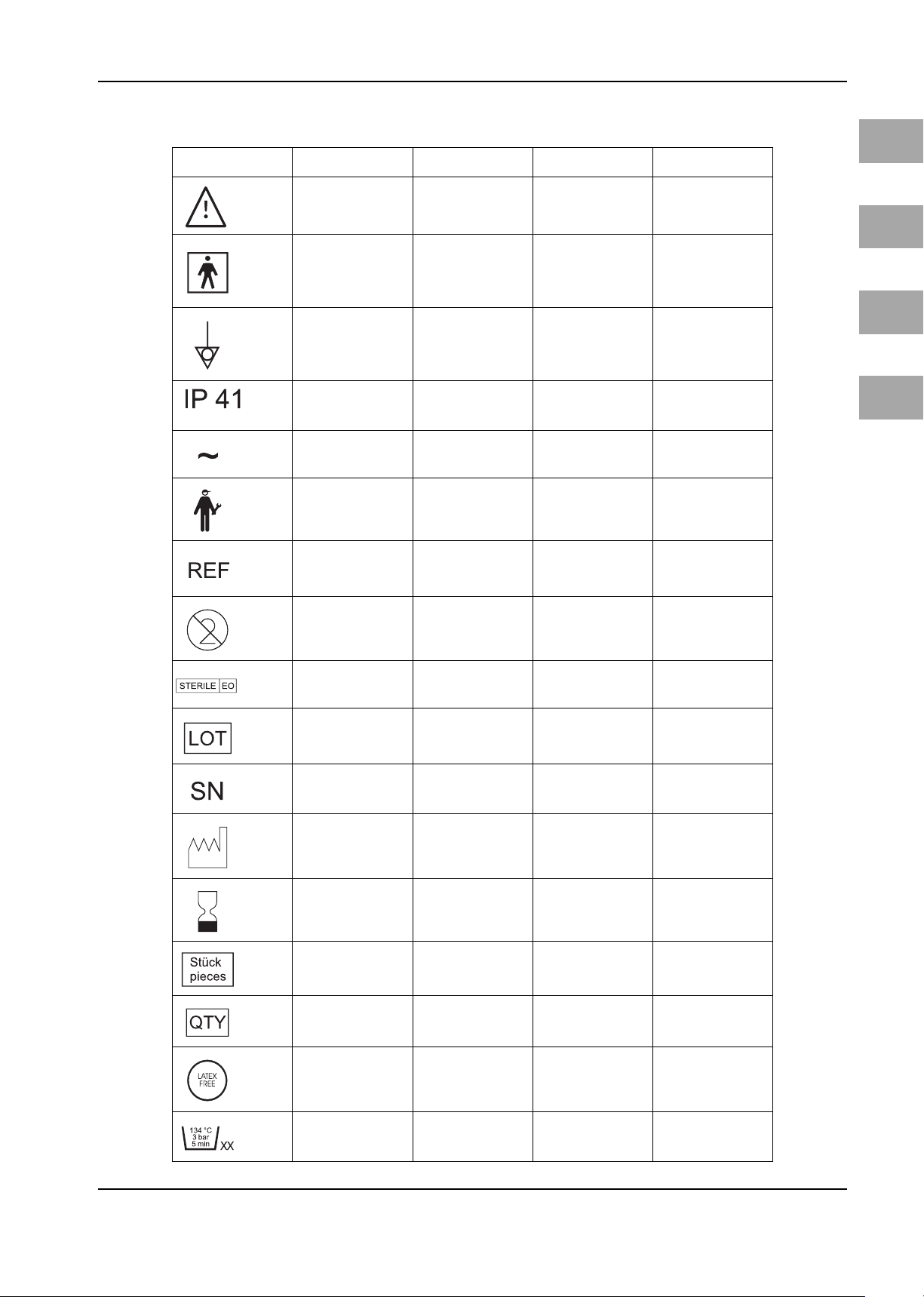
Symbols/Símbolos/Symboles/Símbolos
Symbols Símbolos Symboles Símbolos
EN
See operating manual
Symbol for type BF
equipment
Symbol for potential
equalization
Degrees of protection
provided by enclosures
(IP-Code)
Alternating current
Service
Order number Número de pedido Référence produit Refêrencia
Single use only No reutilizable Usage unique Vedada a reutilização
¡Atención! Observe la
documentación adjunta
Símbolo para un aparato
del tipo BF
Símbolo para la cone-
xión equipotencial
Grado de protección
proporcionado por los
envolventes (Código IP)
Corriente alterna Courant alternatif Corrente alternada
Servicio Service Assistência
Attention, lire la docu-
mentation jointe!
Symbole pour un appa-
reil de type BF
Fiche équipotentielle
Degrés de protection
procurés parles enve-
loppes (Code IP)
Atenção, atentar aos
documentos de expe-
dição
Símbolo para um apare-
lho do tipo BF
Sistema para a compe-
sação do potencial
Classificação do grau de
proteção oferecido
pelas carcaças (IP)
ES
FR
PT
Sterile with ETO Esterilizado con ETO Stérilisés à l’ETO Esterilizado com ETO
Lot no.
Serial number Número de serie Numéro de série Número de série
Date of manufacture Fecha de fabricación Date of fabrication
Expiration day Utilizable hasta Date limite d’utilisation Utilizável até
Pieces, quantity Pieza, cantidad Pièces. quantité Número, quantida
Quantitiy Cantidad Quantité Quantida
Latex free Sin latex sans latex Isento de látex
Denominación
departida o lote
Numéro de lot Designação do lote
Data de fabricação
Number of autoclaving
cycles
Número de esteriliza-
ciones por autoclave
Paramètres pour la sté-
rilisation à l’autoclave
Número de esteriliza-
ções em autoclave
Page 4
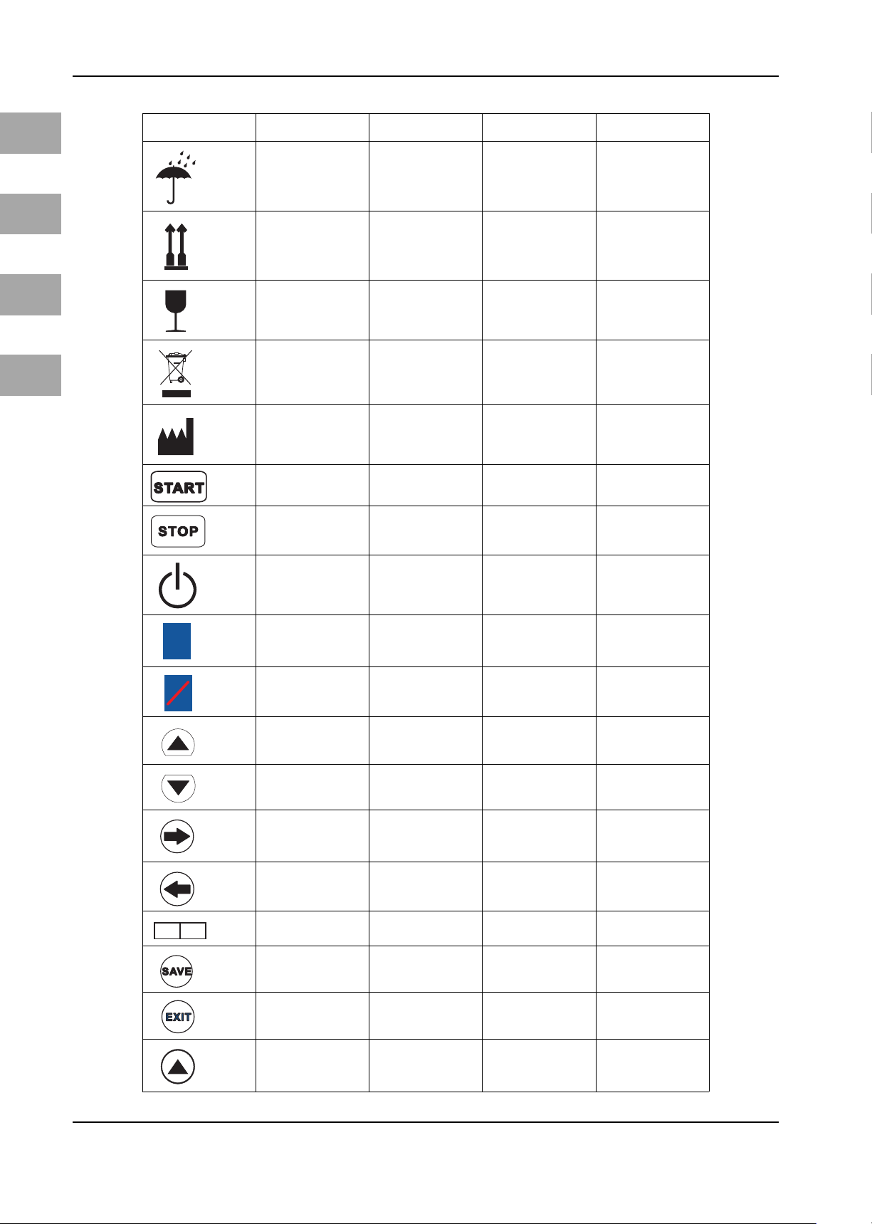
Symbols/Símbolos/Symboles/Símbolos
EN
ES
FR
PT
Symbols Símbolos Symboles Símbolos
Do not get wet
Top-Bottom Arriba-abajo Haut-bas Em cima-Em baixo
Fragile Frágil Fragile Frágil
Waste management Gestión de residuos Élimination des déchets Eliminação
Produced for Producido para Produit pour Produzido para
Start Start (Inicio) Start Start
Stop Stop (Parada) Stop Stop
Proteger contra la
humedad
Protéger de l’humidité Proteger da humidade
EC
HEATING
HEATING
REP
On/Off
Gas heater Calentador del gas Chauffage du gaz Aquecedor do gás
Gas heater error
Increase Aumento Croissant Aumento
Decrease Disminución Décroissant Descida
Forward to menu Remitir al menú Expédier au menu Enviar ao menu
Back to menu Volver al menú Retour au menu Voltar ao menu
Stryker European Repre-
sentative
Save Guardar Mémoriser Guardar
On/Off (Encendido/
Apagado)
Fallo en calentador del
gas
Representante europeo
de Stryker
On/Off (Marche /Arrêt) On/Off (Ligar/Desligar)
Erreur du chauffage du
gaz
Représentant Stryker
Europe
Erro no aquecedor do
gás
Representante Europeu
da Stryker
Exit Salida Sortie Saída
Menu - Increase Menú-Aumento Menu-Croissant Menu-Aumento
Page 5
Symbols/Símbolos/Symboles/Símbolos
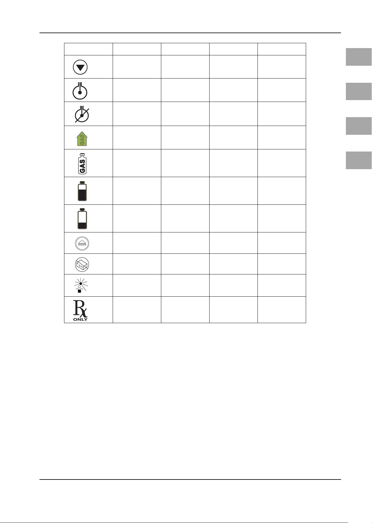
Symbols Símbolos Symboles Símbolos
Menu - Decrease Menú-Disminución Menu-Décroissant Menu-Descida
EN
Real-Time Pressure Sensing in progress
Real-Time Pressure Sensing defective or deacti-
vated
House gas supply
Tank gas supply
Low gas pressure Presión de gas baja Pression de gaz basse Pressão de gás baixa
Gas pressure too low
Push to release Presione para retirar Appuyer pour retirer Premir para eliminar
Do not use if package
damaged
Real-Time Pressure Sen-
sing activada
Real-Time Pressure Sen-
sing defectuosa o
desactivada
Alimentación de gas
central
Alimentación por
botella de gas
Presión de gas dema-
siasdo baja
No utilizar si el envolto-
rio está dañado
Real-Time Pressure Sen-
sing activée
Real-Time Pressure Sen-
sing défectueuse ou
désactivée
Alimentation en gaz
centrale
Alimentation en gaz par
bouteille
Pression de gaz insuffi-
sante
Ne pas utiliser si
l’emballage est endom-
magé
Real-Time Pressure Sen-
sing activada
Real-Time Pressure Sensing danificada o desac-
tivada
Alimentação de gás
doméstico
Alimentação de gás
com uma botija de gás
Pressão de gás dema-
siado baixa
Não usar se a embala-
gem é danificada
ES
FR
PT
Keep away from hea Proteger contra el calor
Authorized for Sale or
use by Physician only
Autorizado sólo para la
venta o el uso médico
Protéger contre la cha-
leur
Autorisé seulement
pour la vente ou l’utili-
sation par un médecin
uniquement
Proteger de encontro ao
calor
Autorizado somente
para a venda ou o uso
médico
Page 6

Page 7

Table of contents
1 Important User Notes ......................................................................................................................................................... 3
2 Safety Information.............................................................................................................................................................. 4
2.1 Hazards........................................................................................................................................................................................ 5
3 Device Purpose.................................................................................................................................................................... 7
3.1 Laparoscopy Applications...................................................................................................................................................... 7
3.1.1 Using High Flow Operating Mode....................................................................................................................................... 7
3.1.2 Using Pediatric Operating Mode.......................................................................................................................................... 7
3.1.3 Using Bariatric Operating Mode.......................................................................................................................................... 8
3.1.4 Contraindications for Laparoscopy Applications............................................................................................................. 8
3.2 Using Vessel Harvest Operating Mode............................................................................................................................... 8
3.3 General Device-Inherent Dangers....................................................................................................................................... 8
3.3.1 Device-Inherent Dangers - Laparoscopy............................................................................................................................ 10
3.3.2 Device-Inherent Dangers - Vessel Harvesting.................................................................................................................. 12
4 Initial Device Startup .......................................................................................................................................................... 14
4.1 Gas connection ......................................................................................................................................................................... 14
4.1.1 Connecting a Gas Bottle......................................................................................................................................................... 15
4.1.2 Connecting to Central Gas Supply....................................................................................................................................... 15
5 Operating the Device - General.......................................................................................................................................... 16
5.1 Front of the Device................................................................................................................................................................... 16
5.2 Rear of the Device .................................................................................................................................................................... 16
5.3 Touch screen display................................................................................................................................................................ 17
5.4 Switch on Device ...................................................................................................................................................................... 18
5.5 Connecting Insufflation Tube Set........................................................................................................................................ 19
5.6 Using the Gas Heating............................................................................................................................................................ 20
5.6.1 Using the direct pressure measurement function (Real-Time Pressure Sensing RTP).......................................... 21
5.6.2 Displaying/Selecting Insufflation Operating Mode ....................................................................................................... 23
5.6.3 Setting the Nominal Pressure - General............................................................................................................................ 23
5.6.4 Setting the Nominal Flow - General ................................................................................................................................... 23
5.6.5 Gas Consumption Display...................................................................................................................................................... 24
5.6.6 Starting/Stopping Insufflation............................................................................................................................................. 24
5.6.7 Using the SIDNE Port (Optional) .......................................................................................................................................... 25
5.6.8 Turning Device Off ................................................................................................................................................................... 25
6 Using and Controlling the PNEUMO SURE High Flow Insufflator in High Flow Mode ...................................................... 26
6.1 Device-Specific Dangers when Using the PNEUMO SURE High Flow Insufflator in High Flow Operating
Mode............................................................................................................................................................................................ 26
6.2 Selecting High Flow Insufflation Mode.............................................................................................................................. 28
6.3 Presetting Nominal Pressure in High Flow Operating Mode....................................................................................... 28
6.4 Presetting Nominal Flow in High Flow Operating Mode.............................................................................................. 28
6.5 Performing the Function Test in High Flow Operating Mode...................................................................................... 29
6.5.1 Filling Tube System with CO2............................................................................................................................................... 31
6.6 Using the Device during Surgery......................................................................................................................................... 31
6.6.1 Insufflating with Veress Cannula......................................................................................................................................... 31
6.6.2 Insufflating with the Trocar................................................................................................................................................... 32
6.6.3 "Real-Time Pressure Sensing" functionality (RTP) ........................................................................................................... 32
6.6.4 Stop the Insufflation................................................................................................................................................................ 32
7 Using and Controlling the PNEUMO SURE High Flow Insufflator in Pediatric Operating Mode....................................... 34
7.1 Device-Specific Dangers when Using the PNEUMO SURE High Flow Insufflator in Pediatric Operating
Mode............................................................................................................................................................................................ 34
7.2 Selecting Pediatric Operating Mode................................................................................................................................... 36
7.3 Presetting Nominal Pressure in Pediatric Operating Mode......................................................................................... 36
7.4 Presetting Nominal Flow in Pediatric Operating Mode ................................................................................................ 37
7.5 Performing the Function Test in Pediatric Operating Mode before Using the Device during Surgery............ 38
7.5.1 Filling Tube System with CO2............................................................................................................................................... 40
7.6 Using the Device during Surgery......................................................................................................................................... 40
7.6.1 Insufflating with Veress Cannula......................................................................................................................................... 40
7.6.2 Insufflating with the Trocar................................................................................................................................................... 41
7.6.3 "Real-Time Pressure Sensing" functionality (RTP) ........................................................................................................... 41
7.6.4 Stop the Insufflation................................................................................................................................................................ 41
8 Using and Controlling the PNEUMO SURE XL High Flow Insufflator in Bariatric Operating Mode................................... 43
8.1 Device-Specific Dangers when Using the PNEUMO SURE High Flow Insufflator in Bariatric Operating
Mode............................................................................................................................................................................................ 43
8.2 Selecting Bariatric Operating Mode.................................................................................................................................... 45
8.3 Presetting Nominal Pressure in Bariatric Operating Mode.......................................................................................... 46
8.4 Presetting Nominal Flow in Bariatric Operating Mode................................................................................................. 46
8.5 Performing the Function Test in Bariatric Operating Mode before Using the Device during Surgery............ 47
8.5.1 Filling Tube System with CO2............................................................................................................................................... 48
8.6 Using the Device during Surgery......................................................................................................................................... 49
8.6.1 Insufflating with Veress Cannula......................................................................................................................................... 49
8.6.2 Insufflating with the Trocar................................................................................................................................................... 49
EN
Page 8

EN
8.6.3 "Real-Time Pressure Sensing" functionality (RTP) ........................................................................................................... 50
8.7 Stop the Insufflation................................................................................................................................................................ 50
9 Using and Controlling the PNEUMO SURE XL High Flow Insufflator in Vessel Harvest Operating Mode......................... 51
9.1 Device-Specific Dangers when Using the PNEUMO SURE XL High Flow Insufflator in Vessel Harvest Ope-
rating Mode ............................................................................................................................................................................... 51
9.2 Selecting Vessel Harvest Operating Mode........................................................................................................................ 52
9.3 Presetting Nominal Pressure in Vessel Harvest Operating Mode.............................................................................. 53
9.4 Presetting Nominal Flow in Vessel Harvest Operating Mode ..................................................................................... 54
9.5 Performing the Function Test in Vessel Harvest Operating Mode before Using the Device during Surgery. 54
9.5.1 Filling Tube System with CO2 ............................................................................................................................................... 55
9.6 Using the Device during Surgery......................................................................................................................................... 56
9.6.1 Insufflation with Vessel Harvest Instrument................................................................................................................... 56
9.6.2 Stop the Insufflation................................................................................................................................................................ 57
10 Configuration Menu (Overview)......................................................................................................................................... 58
10.1 Configuration menu I.............................................................................................................................................................. 60
10.1.1 Setting First Nominal Pressure............................................................................................................................................. 60
10.1.2 Setting the Venting Controls................................................................................................................................................. 61
10.1.3 Setting the Gas Supply Type.................................................................................................................................................. 62
10.1.4 Setting the Alarm Volume..................................................................................................................................................... 63
10.2 Configuration menu II............................................................................................................................................................. 64
10.2.1 Setting the Gas Flow Rates*.................................................................................................................................................. 64
10.2.2 Setting First Nominal Gas Flow*.......................................................................................................................................... 64
10.2.3 Setting the Maximum Nominal Pressure.......................................................................................................................... 65
10.2.4 Setting the Flow Safety Limit*.............................................................................................................................................. 66
10.2.5 Setting the Warning signal: Occlusion .............................................................................................................................. 66
10.3 Utility menu............................................................................................................................................................................... 66
10.3.1 Changing Display Settings..................................................................................................................................................... 67
10.3.2 Setting the Language.............................................................................................................................................................. 67
10.3.3 Checking Software Version.................................................................................................................................................... 68
10.3.4 Upgrade XL* ............................................................................................................................................................................... 69
10.3.5 Service Menu............................................................................................................................................................................. 69
11 Safety functions.................................................................................................................................................................. 70
12 Care and Maintenance........................................................................................................................................................ 74
12.1 Cleaning the Device................................................................................................................................................................. 74
12.2 Annual Inspection .................................................................................................................................................................... 74
12.3 Maintenance by Authorized Service Technician.............................................................................................................. 74
12.4 Replacing the Fuse ................................................................................................................................................................... 75
12.5 Care and Maintenance of Reusable Tube Set................................................................................................................... 75
12.5.1 Cleaning the Reusable Tube Set........................................................................................................................................... 76
12.5.2 Disinfecting the Reusable Tube Set..................................................................................................................................... 76
12.5.3 Sterilization of Reusable Tube Set ....................................................................................................................................... 76
13 Annual Inspection............................................................................................................................................................... 78
13.1 Safety Test................................................................................................................................................................................... 78
13.2 Basic Function Test (in High Flow Operating Mode)...................................................................................................... 78
13.3 Testing the Pressure Sensors in High Flow Operating Mode....................................................................................... 79
13.4 Pressure Monitoring Test in High Flow Operating Mode.............................................................................................. 80
13.5 Venting Valve Test.................................................................................................................................................................... 80
13.6 Max. Device Pressure Test...................................................................................................................................................... 81
13.7 Gas Flow Rate Test.................................................................................................................................................................... 81
14 Electromagnetic compatibility........................................................................................................................................... 82
14.1 Impact of Mobile and Portable HF Communication Devices....................................................................................... 82
14.2 Electrical Connections............................................................................................................................................................. 82
14.3 Accessories ................................................................................................................................................................................. 82
14.4 Guidelines and Manufacturer's Statement - Electromagnetic Interference Immunity....................................... 83
14.5 Guidelines and Manufacturer’s Statement – Electromagnetic Emissions.............................................................. 84
14.6 Guidelines and Manufacturer's Statement - Electromagnetic Interference Immunity - PNEUMO SURE
High Flow Insufflator .............................................................................................................................................................. 85
14.7 Recommended Safety Distances Between Portable and Mobile HF Telecommunications Devices and the
PNEUMO SURE High Flow Insufflator................................................................................................................................. 86
15 Error and Warning Messages.............................................................................................................................................. 87
16 Technical Data..................................................................................................................................................................... 89
17 Accessories for PNEUMO SURE High Flow Insufflator........................................................................................................ 90
17.1 Accessories for Sale in USA.................................................................................................................................................... 90
17.2 Accessories for Sale Outside of the USA............................................................................................................................ 91
18 Warranty and Service ......................................................................................................................................................... 93
19 Appendix............................................................................................................................................................................. 95
19.1 Test Log........................................................................................................................................................................................ 95
Index ................................................................................................................................................................................... 96
Page 9
1Important User Notes
Read the manual carefully and become familiar with the operation and function
of the device and the accessories before use during surgical procedures. Non-observance of the instructions listed in this manual can lead
• to life-threatening injuries of the patient,
• to severe injuries of the surgical team, nursing staff or service personnel, or
• to damage or malfunction of device and/or accessories.
technical data of the supplied product through continued product development.
marked with these words must be read especially attentively.
WARNING!
The safety and/or health of the patient, user, or a third party are at risk. Comply
with this warning to avoid injury to the patient, user, or third parties.
CAUTION!
These paragraphs include information provided to the operator concerning the
intended and proper use of the device or accessories.
Important User Notes
EN
Subject to technical changesThe manufacturer reserves the right to modify the appearance, graphics, and
Please noteThe words DANGER, WARNING, and NOTE carry special meanings. Sections
NOTE!
Here you will read information about the maintenance of the device or the ac-
cessories.
3
Page 10

EN
Safety Information
2 Safety Information
Federal Law (only for U.S. market) U.S. federal law restricts use of this device to use by or on the o rder of a p hysici an.
Exclusion of liability The manufacturer is not liable for direct or consequential damage and the war-
ranty is null and void if:
• the device and/or the accessories are improperly used, prepared, or maintained,
• the instructions and rules in the manual are not adhered to,
• non-authorized persons perform repairs, adjustments, or alterations on or to
the device or accessories,
• non-authorized persons open the device,
• the prescribed inspection and maintenance schedules are not adhered to.
Receipt of technical documentation from the manufacturer does not authorize
individuals to perform repairs, adjustments, or alterations on or to the device or
accessories.
Authorized service technician Only an authorized service technician may perform repairs, adjustments, or al-
terations on the device or accessories and use the service menu. Any violation will
void the manufacturer's warranty. Authorized service technicians are only
trained and certified by the manufacturer.
Care and maintenance The service and maintenance of the device and its accessories has to be carried
out as per instructions to ensure the safe operation of the device. For the protection of the patient and the operating team, check that the device is complete and
functional before each use.
Contamination Before shipping, decontaminate device and accessories in order to protect the
service personnel. Follow the instructions listed in this manual. If this is not possible,
• the product must be clearly marked with a contamination warning and
• is to be double-sealed in safety foil.
The manufacturer has the right to reject contaminated products for repair.
Waste management
This symbol indicates that the waste of electrical and electronic equipment must
not be disposed of as unsorted municipal waste and must be collected separately
instead. Please contact the manufacturer or an accordingly authorized disposal
or waste management company for further information.
4
Page 11
Safety Information
2.1 Hazards
WARNING!
Condensation / Water penetration
Protect device from moisture. Do not use if moisture has penetrated the device.
WARNING!
Original accessories
For your own safety and that of your patient, use only original accessories.
WARNING!
Check all factory settings.
Factory settings are not mandatory settings for the physician. The physician is re-
sponsible for all settings affecting the surgical procedure.
WARNING!
Technique and procedures
Only the physician can evaluate the clinical factors involved with each patient
and determine if the use of this device is indicated. The physician must deter-
mine the specific technique and procedure that will accomplish the desired clinical effect.
EN
CAUTION!
Check to make sure the available mains voltage matches the data listed on the
type label attached to the back of the device. Incorrect voltage can cause errors
and malfunctions and may destroy the device.
WARNING!
Not explosion-proof
The device is not explosion-proof. Do not use in an area where flammable anes-
thetic gases are present.
WARNING!
Risk of electrical shock
To prevent electrical shock, do not open this device. Never open this device your-
self. Refer servicing to qualified service personnel.
WARNING!
Replacing fuse
Replace the fuse only with a fuse of the same type and rating.
WARNING!
Professional qualification
This manual does not include descriptions or instructions for surgical proce-
dures/techniques. It is also not suitable for training physicians in the use of surgical techniques. Medical accessories and devices may be used only by physicians
and medical assistants under the direction of a physician with the appropriate
5
Page 12
EN
Safety Information
technical qualification.
WARNING!
Function test
The function test must be performed prior to each surgery.
WARNING!
Sterile mediums and accessories
Always work exclusively with sterile substances and mediums, sterile fluids, and
sterile accessories if so indicated.
WARNING!
Cleaning the device
Do not sterilize the device.
WARNING!
Replacement device and accessories
In case the device or any of the accessories fail during surgery, a replacement device and replacement accessories should be kept within easy reach to be able to
finish the operation with the replacement components.
WARNING!
Device-inherent dangers
Read the warnings specific to this device in chapter 3.3 General Device-Inherent
Dangers.
WARNING!
Device defect
If a device defect is suspected or confirmed, do not use it. Make sure the device
can no longer be used until a qualified service technician conducts the appropriate tests and repairs.
CAUTION!
Endoscope
The device may only be connected with endoscopes designed for and featuring
the technical specification permitting such a combined use. Any utilized endoscopes must comply with the most recent versions of EC 60601-2-18 and
ISO 8600.
6
Page 13

3 Device Purpose
CO2 during diagnostics and/or therapeutical laparoscopy. High Flow operating
mode, Pediatric operating mode, and Bariatric operating mode of the device are
used in conjunction with a laparoscope to fill and distend a peritoneal cavity with
gas. Pediatric operating mode is designed specifically for use on newborns, infants, and children. Vessel Harvest operating mode is used to create a cavity
along the saphenous vein and/or the radial artery during an endoscopic vessel
harvesting procedure.
Two alternative configurations are provided:
1. PNEUMO SURE High Flow Insufflator contains the applications
High Flow operating mode -> Insufflation for adults and the
Pediatric operating mode -> Insufflation for infants and children.
2. PNEUMO SURE XL High Flow Insufflator contains the applications
High Flow operating mode -> Insufflation for adults and the
Pediatric operating mode -> Insufflation for infants and children,
Bariatric operating mode -> Insufflation for morbidly obese patients,
Vessel Harvest operating mode -> Insufflation for Vessel Harvesting proce-
dure.
Device Purpose
Intended useThe PNEUMO SURE High Flow Insufflator serves to create a cavity by insufflating
EN
The PNEUMO SURE XL configuration is available directly or via software upgrade.
High Flow operating mode, Pediatric operating mode, and Bariatric operating
mode of the device are used in conjunction with a laparoscope to fill and distend
a peritoneal cavity with gas. Bariatric operating mode is used for laparoscopic
surgery on morbidly obese patients.
Vessel Harvesting operating mode is used to create a cavity along the saphenous
vein and/or the radial artery during an endoscopic vessel harvesting procedure.
3.1 Laparoscopy Applications
3.1.1 Using High Flow Operating Mode
High Flow operating mode is designed explicitly for laparoscopies performed on
normal weight and slightly obese (BMI < 30 kg/m2) patients over the age of 14.
While in High Flow operating mode, the insufflator limits the pressure to max. 30
mm Hg and the gas flow rate to max. 40 l/min. The device measures the pressure
within the abdomen and compares the nominal with the actual abdominal pressure. The function of the device is to maintain the nominal pressure. Any overpressure within the abdomen is lowered to the preset nominal pressure by the
automatic venting system.
3.1.2 Using Pediatric Operating Mode
Pediatric operating mode is designed specifically for use on newborns, infants,
and children. While in Pediatric operating mode, the insufflator limits the pressure to max. 20 mmHg and the gas flow rate to max. 20 l/min. When used on
children, the device should be set depending on the selected nominal flow and
the age and weight of the treated child as outlined in the table below:
Age Group Weight Flow Range
Children younger than 1
year
Children between 1 and
3 years
Children between 3 and
4 years
Children between 4 and
14 years
approx. 1-9 kg 0.1 -0.5 l/min
approx. 10-15 kg 0.5 -1.0 l/min
approx. 16-19 kg 1.0 -2.0 l/min
> 20 kg > 2.0 l/min
7
Page 14
EN
Device Purpose
If the nominal flow is set too low, the nominal pressure cannot be reached. Check
for possible leaks. Due to the special operating method used during the Pediatric
application, the speed of equalizing the leak is slower than when using the High
Flow application (lower effective flow in the Pediatric application).
3.1.3 Using Bariatric Operating Mode
Bariatric operating mode is used for laparoscopies performed on severely overweight (BMI > 30 kg/m
pressure to max. 30 mm Hg and the gas flow to max. 45 l/min. This operating
mode delivers rapid insufflation of large volumes.
2
) adults. While in Bariatric mode, the insufflator limits the
3.1.4 Contraindications for Laparoscopy Applications
Contraindications The device may not be used to fill an abdomen with CO2 if a laparoscopy is con-
traindicated. Please consult the manual of your laparoscope for absolute and relative contraindications. The device is not suitable for hysteroscopic insufflations,
i.e., it may not be used to distend the uterus.
The gas flow may not exceed 14 l/min when performing a laparoscopy on infants
or patients weighing less than 25 kilos.
3.2 Using Vessel Harvest Operating Mode
WARNING!
Before using the insufflator to harvest vessels, please check whether the used in-
strument is intended for surgical procedures using CO2.
Vessel Harvest operating mode is designed for the controlled insufflation of
medical-grade CO2 when harvesting vessels (veins and arteries) during a minimally invasive procedure within the scope of heart bypass surgery. While in Vessel Harvest operating mode, the insufflator limits the pressure to max.
20 mm Hg and the gas flow rate to max. 10 l/min. Surgery to harvest vessels requires the use of a special instrument.
Contraindications The device may not be used for the endoscopic harvesting of vessels if this surgi-
cal application is contraindicated. Please consult the manual of the instrument
for absolute and relative contraindications.
3.3 General Device-Inherent Dangers
WARNING!
Positioning the patient
Always position the patient lower than the device to prevent body fluids from
leaking into the insufflation tube. Actual pressure may increase and fluid may
penetrate the insufflation tube if the patient is repositioned during surgery. If
this occurs, immediately disconnect the insufflation tube. When the patient is
repositioned onto his or her side, internal tissue may block the insufflation channel. Always insufflate through the elevated side of the patient.
WARNING!
Removing the insufflation tube
Always disconnect the insufflation tube after ending surgery and before switch-
ing off the device to prevent backflow of bodily fluids. Fluid may penetrate the
insufflation tube whenever you change the gas bottle and/or when you stop the
gas flow during the operation. If this happens, you must immediately disconnect
the insufflation tube from the trocar or from the device.
8
Page 15
WARNING!
Backflow
Body secretions or contaminated gas may backflow into the device through the
insufflation tube if
• a filter is not used,
• the actual pressure is higher than the nominal pressure or
• the automatic venting valve is activated.
WARNING!
Gas flow
A high gas flow can occur due to large leaks within the surgical system or instru-
ment. This can result in a false actual pressure reading, which in turn may endanger the patient. In case of a disrupted gas flow, you should therefore inspect
device, tube, and instruments immediately. Surgical applications should be carried out with a gas flow of 4-10 l/min. An even lower gas flow is recommended
for diagnostic purposes. It is recommended to perform endoscopies with the
lowest gas flow possible.
WARNING!
Keep filled CO2 bottle on hand
Always keep a filled CO2 bottle on hand ready for replacement. This avoids hav-
ing to interrupt surgery due to a lack of insufflation gas (see chapter 4.1.1 Connecting a Gas Bottle).
Device Purpose
EN
WARNING!
Contamination
Do not use device and/or accessories if signs of contamination are detected.
Make sure the device or/and accessories can no longer be operated until a qual-
ified service technician conducts the appropriate tests and repairs.
WARNING!
Fatigue symptoms
When there is a high level of CO2 consumption, you should make sure to supply
the operating area with enough fresh air, since an increasing CO2 level in the air
can cause the medical personnel to suffer fatigue symptoms, an inability to concentrate, unconsciousness, or even death.
WARNING!
The venting rate of the automatic venting system is limited. Always monitor the
actual pressure when using additional insufflation sources.
WARNING!
Contaminated filter
Replace a contaminated filter immediately during surgery to ensure unhindered
gas flow.
WARNING!
Connecting the tube
Always use the proper tube set for the device. The tube outlet may only be con-
9
Page 16
EN
Device Purpose
nected to instruments which are intended for intra-abdominal CO2-insufflation.
WARNING!
Electronic device control
Do not close the valve at the trocar sleeve during surgery. The electronic control
unit of the device adjusts the actual pressure as desired.
WARNING!
Medically pure CO2
Make sure to use only medically pure CO2. Other gases (i.e., helium, N2O, argon),
mixtures of gases, high pressure compressed gases, gases with entrapped liquids, or polluted gases must not be used with this device.
WARNING!
Service connection
Connected devices have to comply with the EN 60950 standard. Do not connect
a device to the service connection during surgery.
CAUTION!
Electrical Interference
(See chapter 14 Electromagnetic compatibility). Electrical interference with other devices or instruments was practically eliminated when developing this devic-
es and none was detected during testing. However, if you still detect or suspect
such interference, please follow these suggestions:
• Move this, the other or both devices to a different location
• Increase distance between used devices
• Consult an electro-medical expert
WARNING!
Peripheral devices
Additional peripheral equipment connected to interfaces of the medical monitor
has to meet the requirements of the following specifications: IEC 60601-2-18 /
EN 60601-2-18 for endoscopic devices and IEC 60601-1 / EN 60601-1 for electrical medical devices. All configurations have to comply with IEC 60601-1 / EN
60601-1 specifications. Whoever connects additional equipment to signal output or signal input is considered the system configurator and as such is responsible for complying with requirements of the standard IEC 60601-1 / EN 60601-1.
3.3.1 Device-Inherent Dangers - Laparoscopy
WARNING!
Because pediatric patients are especially susceptible to hypercapnia, it is recom-
mended to establish an end-tidal CO2 monitoring routine.
10
WARNING!
Gas flow limit
The gas flow may not exceed 14 l/min when performing a laparoscopy on new-
borns or patients weighing less than 25 kg (approx. 55 US pounds).
Page 17
WARNING!
Pneumolabium/pneumoscrotum
Children are at risk of a pneumolabium or pneumoscrotum.
WARNING!
Increased airway pressure/compression of the vena cava
When using the pediatric application of the device on children, an increased risk
of high airway pressure and/or compression of the vena cava (low input syndrome) exists.
WARNING!
Idiosyncratic reactions
Patients with sickle cell anemia or pulmonary insufficiency may have a higher
risk of metabolic imbalance related to excessive CO2 absorption (idiosyncratic
reaction).
WARNING!
CO2 absorption
CO2 is absorbed during insufflation (intravasation). This means the body absorbs
part of the CO2 gas used for insufflation. CO2 concentrations in the blood or respiratory system that are too high can lead to death of the patient in extreme
cases. To lower this risk, always carefully and closely monitor the patient's vital
signs during the entire insufflation process and make sure patient is breathing
well. Sufficient respiration can help avoid or limit problems with CO2. High pressure or a high gas flow promotes CO2 absorption. The abdomen is sufficiently
distended using a pressure between 10 to 15 mm Hg. Pressure values above
15 mm Hg are required for only a few cases but do increase the risk of intravasation. Never exceed the max. intra-abdominal pressure of 30 mm Hg.
Device Purpose
EN
WARNING!
Metabolic and cardiac reactions
Insufflating CO2 may result in metabolic acidosis. This can lead to cardiac irregularities expressed with the following symptoms:
• Reduced respiration with restricted diaphram function
• Hypercapnia
• Reduction of venous reflux
• Reduced cardiac output
• Metabolic acidosis
WARNING!
Hypothermia/monitoring body temperature
The gas flow can lead to a lowering of the patient's body temperature during in-
sufflation. Hypothermia during insufflation can cause heart and cardiovascular
problems. The risk for hypothermia can be significantly reduced with the use of
gas that is pre-warmed to body temperature. Always monitor the patient's body
temperature during the entire insufflation. Make especially sure that the following, hypothermia promoting, surgical conditions are avoided as best as possible:
• High gas flow due to large leaks
• Long surgeries
• Use of cold (not preheated) irrigation and infusion solutions
11
Page 18
EN
Device Purpose
WARNING!
Dehydration
Insufflation can lead to dehydration of the tissue. This can result in organ tissue
damage and cardiovascular reactions of the patient. Long surgeries and large
leaks increase the risk of dehydration (especially at the insertion points of the
trocars or when changing instruments).
WARNING!
Embolism
Improper placement of the insufflation instrument could cause insufflation of
gas into a vessel, resulting in air or CO2 embolisms. To reduce the risk of air or
CO2 embolism, perform initial insufflation at a low flow rate and ensure that the
insufflation instrument is correctly positioned. Check the position of the insufflation instrument immediately if the actual pressure rapidly reaches the nominal pressure value. CO2 embolisms can also be caused by a high intra-abdominal
pressure. Avoid high-pressure settings and close damaged blood vessels at once.
WARNING!
Additional insufflation sources
The use of additional insufflation sources increases the intra-abdominal pressure. Continuously monitor intra-abdominal pressure over the course of the en-
tire insufflation if additional sources are used.
WARNING!
Automatic venting system
Make sure the automatic venting system is activated (see chapter 10 Configura-
tion Menu (Overview), page 58) when using Pediatric application and an additional insufflation source. It is not possible to use an additional insufflation
source when the automatic venting system is deactivated.
WARNING!
Only specially trained and qualified personnel may use this device on children or
for the endoscopic vessel harvesting procedure.
3.3.2 Device-Inherent Dangers - Vessel Harvesting
WARNING!
Before using the insufflator to endoscopic harvest vessels, please check whether
the used instrument is intended for CO2 insufflation.
WARNING!
Pneumoperitoneum
When a vessel is harvested from the leg of a patient with a perforated groin, it is
possible for CO2 to reach the abdomen and cause a pneumoperitoneum. Make
sure the abdomen does not fill with CO2 during surgery.
12
WARNING!
Idiosyncratic reactions
Patients with sickle cell anemia or pulmonary insufficiency may have a higher
risk of metabolic imbalance related to excessive CO2 absorption (idiosyncratic
Page 19
reaction).
WARNING!
CO2 absorption
Due to the special surgical procedures - start of the heart bypass operation, and
the endoscopic removal of the vessel - special care has to be taken as CO2 is al-
ways absorbed through the tissue of the patient during insufflation (intravasation). This means the body absorbs part of the CO2 gas used for insufflation. CO2
concentrations in the blood or respiratory system that are too high can lead to
death of the patient in extreme cases. To lower this risk, always carefully and
closely monitor the patient's vital signs during the entire insufflation process
and make sure patient is breathing well. Sufficient respiration can help avoid or
limit problems with CO2. High pressure or a high gas flow promotes CO2 absorption.
WARNING!
Metabolic and cardiac reactions
Due to the special surgical conditions - start of the heart bypass surgery and vessel harvesting - it is especially important to remember the existing risk of meta-
bolic acidosis when insufflating with CO2. This can lead to cardiac irregularities
expressed with the following symptoms:
• Reduced respiration with restricted diaphram function
• Hypercapnia
• Reduction of venous reflux
• Reduced cardiac output
• Metabolic acidosis
Device Purpose
EN
WARNING!
Dehydration
Insufflation can lead to dehydration of the tissue. This can result in organ tissue
damage and cardiovascular reactions of the patient. Long surgeries and large
leaks increase the risk of dehydration (especially at the insertion points of the
trocars or when changing instruments).
WARNING!
Embolism
Improper placement of the insufflation instrument could cause insufflation of
gas into a vessel, resulting in air or CO2 embolisms. To reduce the risk of air or
CO2 embolism, perform initial insufflation at a low flow rate and ensure that the
insufflation instrument is correctly positioned. Check the position of the insufflation instrument immediately if the actual pressure rapidly reaches the nominal pressure value. CO2 embolisms can also be caused by a high pressure. Avoid
high-pressure settings and close damaged blood vessels at once.
WARNING!
Only specially trained and qualified personnel may use this device on children or
for the endoscopic vessel harvesting procedure.
13
Page 20
EN
Initial Device Startup
4 Initial Device Startup
Delivery inspection Always check all parts and accessories of the device immediately after receiving
the shipment. The manufacturer considers only replacement claims that have
been immediately submitted or reported to a sales representative or an authorized service company.
Setting up the device Place the device on a level surface and install in a dry environment. The ambient
temperature and humidity must meet the requirements mentioned in chapter
16 Technical Data, page 89.
WARNING!
Not explosion-proof
The device is not explosion-proof. Do not use in an area where flammable anes-
thetic gases are present.
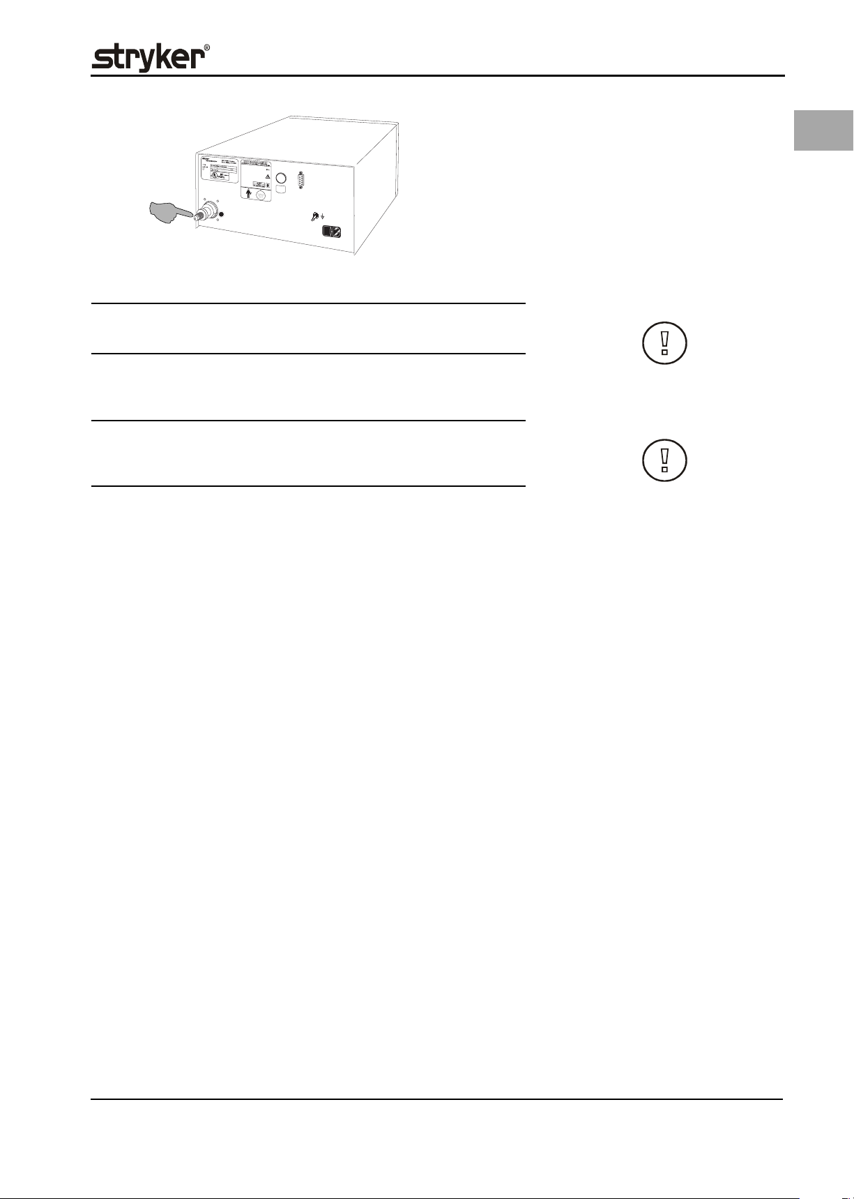
Mains connection
CAUTION!
Check to make sure the available mains voltage matches the data listed on the
type label attached to the back of the device. Incorrect voltage can cause errors
and malfunctions and may destroy the device.
Make sure the connection data and technical specifications of the power supply
comply with DIN VDE or national requirements. The mains power supply cable
must be plugged into a properly installed safety wall plug (see DIN VDE 0107).
Read the device label located in rear of device (type plate) to determine the operating voltage of the device.
Grounding contact The power connection must be equipped with a grounding contact. Use the orig-
inal power cable (if included in scope of delivery) to establish a connection between the mains wall socket and the non-heating device plug located in the rear
of the device.
Only for U.S. operators Only use a certified (UL-listed), removable mains connection line, type SJT, mini-
mal 18 AWG, 3 leads. The plug connectors must comply with NEMA 5-15 or IEC
320/CEE22. Grounding will only be reliable if the equipment is connected to a
corresponding hospital grade socket.
Potential equalization Integrate the device into the potential equalization system as specified by local
safety rules and regulations.
4.1 Gas connection
WARNING!
Medically pure CO2
Make sure to use only medically pure CO2. Other gases (i.e., helium, N2O, argon),
mixtures of gases, high pressure compressed gases, gases with entrapped liq-
uids, or polluted gases must not be used with this device.
14
Use a high-pressure tube to connect a CO2 gas cylinder to the rear gas inlet connection or connect to centralized CO2 gas supply.
Page 21
CO
2
4.1.1 Connecting a Gas Bottle
CAUTION!
Always use a high-pressure tube to connect gas bottle and device.
The gas bottle must be in a vertical position. The gas bottle pressure may not exceed 80 bar or be less than 15 bar.
CAUTION!
Gas bottles with riser pipe can release dirt and oily fluids into the device. Do not
use a gas bottles with riser pipe.
Initial Device Startup
EN
4.1.2 Connecting to Central Gas Supply
Use the following device connectors available as additional equipment to connect to a central gas supply (house supply):
• 0620-040-003 for NIST house gas supply or
• 0620-040-002 for DISS house gas supply.
1. Attach the high-pressure tube to the gas connection.
2. Fix the high-pressure tube with the nut.
3. Tighten the nut.
The type of corresponding gas supply must be set in the configuration menu (see
chapter 10.1.3 Setting the Gas Supply Type, page 62).
15
Page 22
EN
Operating the Device - General
5 Operating the Device - General
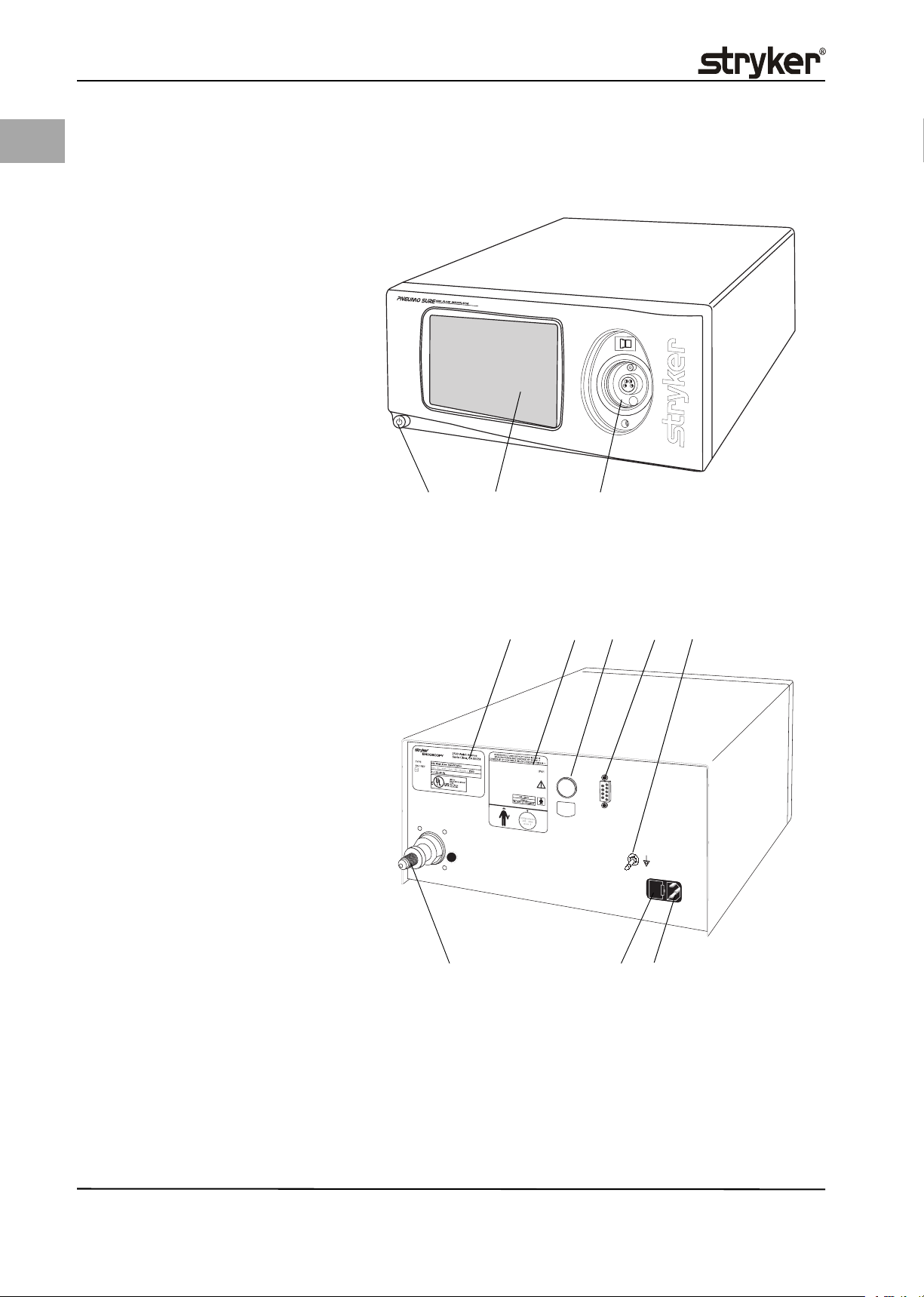
5.1 Front of the Device
Fig. 5-1 Device Front
(1) ON/OFF switch
(2) Touch screen display
(3) Insufflation tube connection
(1) (2) (3)
Fig. 5-2 Device Rear
(4) Type plate
(5) Device data plate
(6) SIDNE interface (optional)
(7) Data input/output
(8) Connection for potential equaliza-
tion
(9) Device plug
(10) Fuse holder
(11) Gas supply connection
Familiarize yourself with the control and function elements at the front of the device.
5.2 Rear of the Device
(4) (5) (6)
CO
2
(11) (9)(10)
(7) (8)
16
Familiarize yourself with the connection elements at the rear of the device.
Page 23
Operating the Device - General
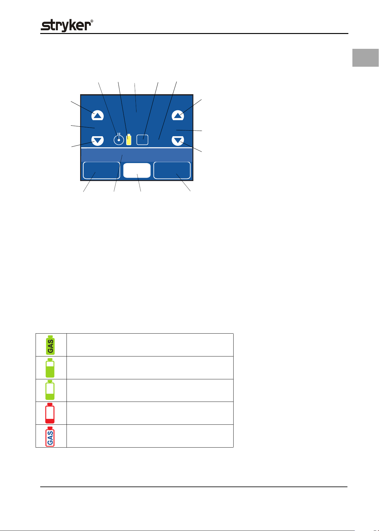
5.3 Touch screen display
(1)
(15)
(14)
(13)
Set Pressure
mm Hg
15
Actual Pressure
mm Hg
0
GAS
Mode: High Flow
Change
Mode
The above depiction of the touch screen also shows all display and function
fields. Field (9) serves as actual flow display (depicted without frame while insufflating) and also as menu function field (depicted with frame).
Field (12) serves as insufflation operating mode display (depicted without frame
while insufflating) and also as control field for selecting the insufflation operating mode (depicted with frame).
START
0.0
Liter
(4)(2) (3) (5)
Set Flow
l/min
3
HEATING
Actual
0
(6)
(7)
(8)
l/min
(9)(10)(11)(12)
EN
Fig. 5-3 Screen displays
(1) Continuous pressure reading dis-
play
(2) Gas supply display
(3) Actual pressure display
(4) Gas consumption display/func-
tion field for reset
(5) Gas heating connected/ready
(6) Increasing nominal gas flow
(7) Nominal gas flow display
(8) Decreasing nominal gas flow
(9) Actual gas flow display/ menu
function field
(10) START/STOP function field
(11) Status display/error and warning
messages
(12) Insufflation operating mode dis-
play/selecting insufflation operating mode
(13) Decreasing nominal pressure
(14) Nominal pressure display
(15) Increasing nominal pressure
Press the function field (9) or (12) depicted with frame and hold for 2 seconds to
trigger functions or set values. Additional explanations for individual elements
are presented in the subsequent respective control element descriptions.
bols and acoustic signals (see chapter 11 Safety functions for gas pressure display
information).
> 50 bar
40 - 50 bar
30 - 40 bar
15 - 30 bar; Three warning signals can be heard and the message
"Change gas tank" is displayed. User is advised to obtain a replacement tank.
< 15 bar; Three warning signals can be heard and the message
"Check gas supply" is displayed. Replace gas tank immediately.
Gas supply displaysThe status of the gas supply is monitored by the device and indicated with sym-
Gas supply with gas bottleThe following gas bottle pressures are displayed:
If gas supply pressure declines further, there are warnings to remind the user to
replace the gas tank immediately. Five warning signals can be heard and the
message "Check gas supply" is displayed at < 5 bar and again at 0 bar. Insufflation
stops at 0 bar.
17
Page 24
EN
Operating the Device - General
House gas supply The following house gas supply pressures are displayed:
House gas supply pressure OK
(green)
House gas supply pressure too low
(red)
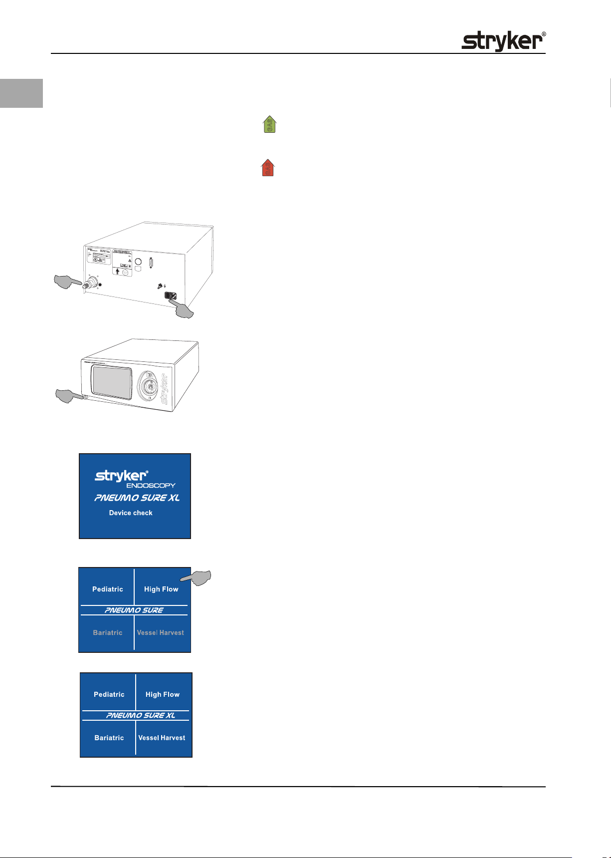
5.4 Switch on Device
1. Connect with mains power supply.
2. Connect the gas supply to the gas connection port and open the gas supply.
(2)
(3)
CO
2
(1)
3. Press the ON/OFF switch. The device switches on.
4. After being switched on, the device performs a device check. The touch screen
depicts the company logo as well as the lines PNEUMO SURE respectively
PNEUMO SURE XL ->Device check ->Device OK is visible for 3 seconds after
the successful completion of the device check. In case the device check failed
and error message is displayed please see chapter 15 Error and Warning Messages for advises.
5. The display depicts an insufflation operating modes overview. Unavailable
operating modes are depicted in gray and cannot be selected. Press the respective function field to select the corresponding desired operating mode
(e.g. High Flow).
18
Page 25
Operating the Device - General
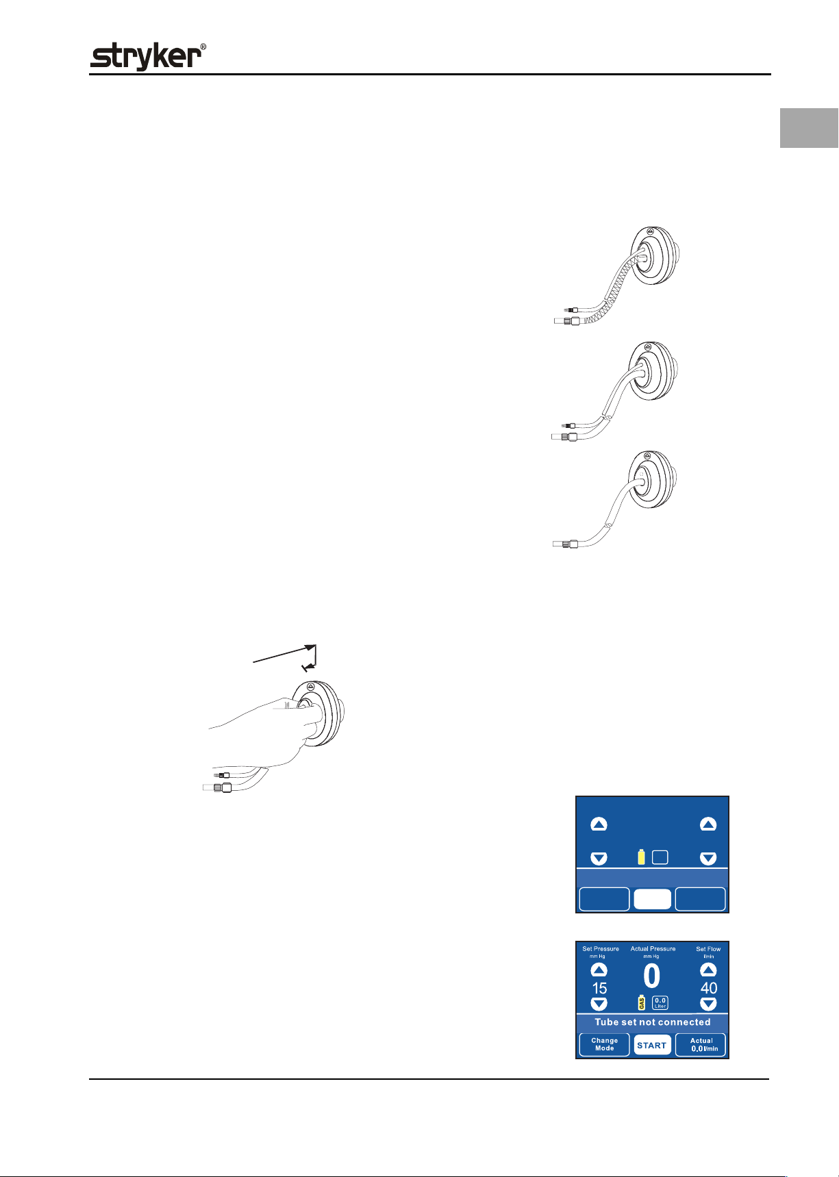
5.5 Connecting Insufflation Tube Set
Three different insufflation tube set types can be connected to the insufflation
tube connection at the front of the device (see Fig. 5-1 Device Front, page 16,
(3)).
Heated tube set with
Real-Time Pressure
Sensing (RTP)
High Flow tube set
with Real-Time Pressure Sensing (RTP)
High Flow II tube set Disposable (single use) insufflation tube set with:
Disposable (single use) insufflation tube set with:
• Filter
• Gas heating
• Measuring tube for direct pressure measurement
(RTP)
Disposable (single use) insufflation tube set with:
• Filter
• Measuring tube for direct pressure measurement
(RTP)
• Filter
EN
connection at the front of the device until it snaps firmly into place.
• A short acoustic warning signal is emitted,
• the message Tube set connected is displayed,
• a check mark is displayed.
If the tube is accidentally unlatched by pressing twice or if the tube is removed
during insufflation:
• 2 long acoustic warning signal are emitted,
• the message Tube set not connected is displayed,
Connecting the tube setInsert the plug of the insufflation tube set correctly into the insufflation tube set
Set Pressure
mm Hg
Actual Pressure
mm Hg
15
Change
Mode
ü
0.0
GAS
Liter
Tube set connected
START
START
Set Flow
Actual
0
l/min
3
l/min
19
Page 26
EN
Operating the Device - General
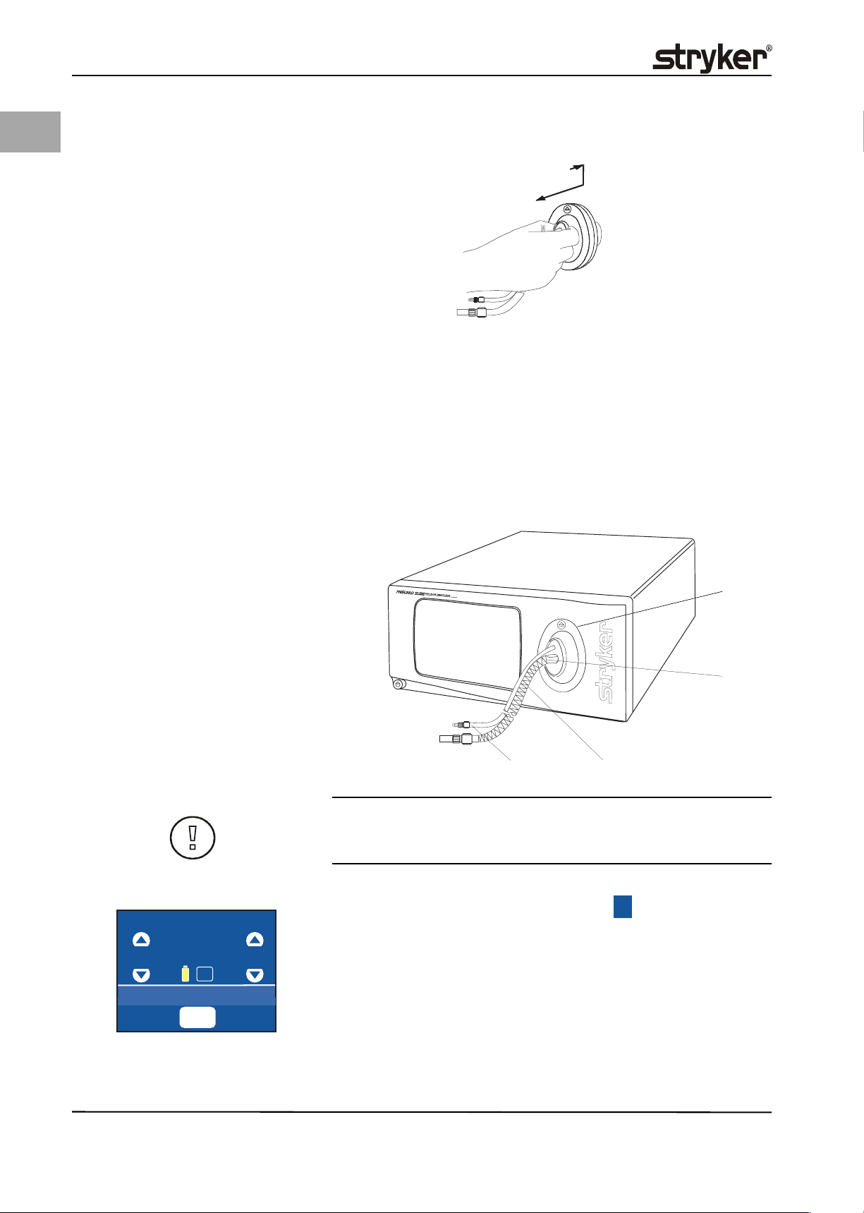
Removing the tube set Press the plug of the insufflation tube in the direction of the device. This releases
the snap-in latch and you are now able to remove the insufflation tube set.
• 2 long acoustic warning signal are emitted,
• the message Tube set not connected is displayed,
5.6 Using the Gas Heating
Connecting the gas heating Use the heating tube to insufflate lukewarm gas (37° C).
1. Switch device on.
2. Connect an insufflation tube with gas heating (Heated tube set with RealTime Pressure Sensing (RTP).
The heating module is located directly in the insufflation tube.
Fig. 5-4 Connecting the gas heating
(1) Plug for insufflation tube with gas
heating
(2) Internal heating
(1)
(3) Insufflation tube
(4) Measuring tube
(2)
(4)
(3)
CAUTION!
Do not subject the heater tube to direct heat (e.g., operating room lamp, en-
doscop with light source) or high room temperatures.
Gas heating display The device automatically determines whether a tube set with or without gas
Set Pressure
mm Hg
Actual Pressure
mm Hg
Set Flow
l/min
heating is connected. The display depicts a symbol and the status line reads
Gas heater OK after the successful detection of the corresponding tube set.
HEATING
20
15
Mode
High Flow
0
0.0
Liter
GAS
Gas heater OK
STOP
HEATING
Actual
3
3
l/min
Page 27

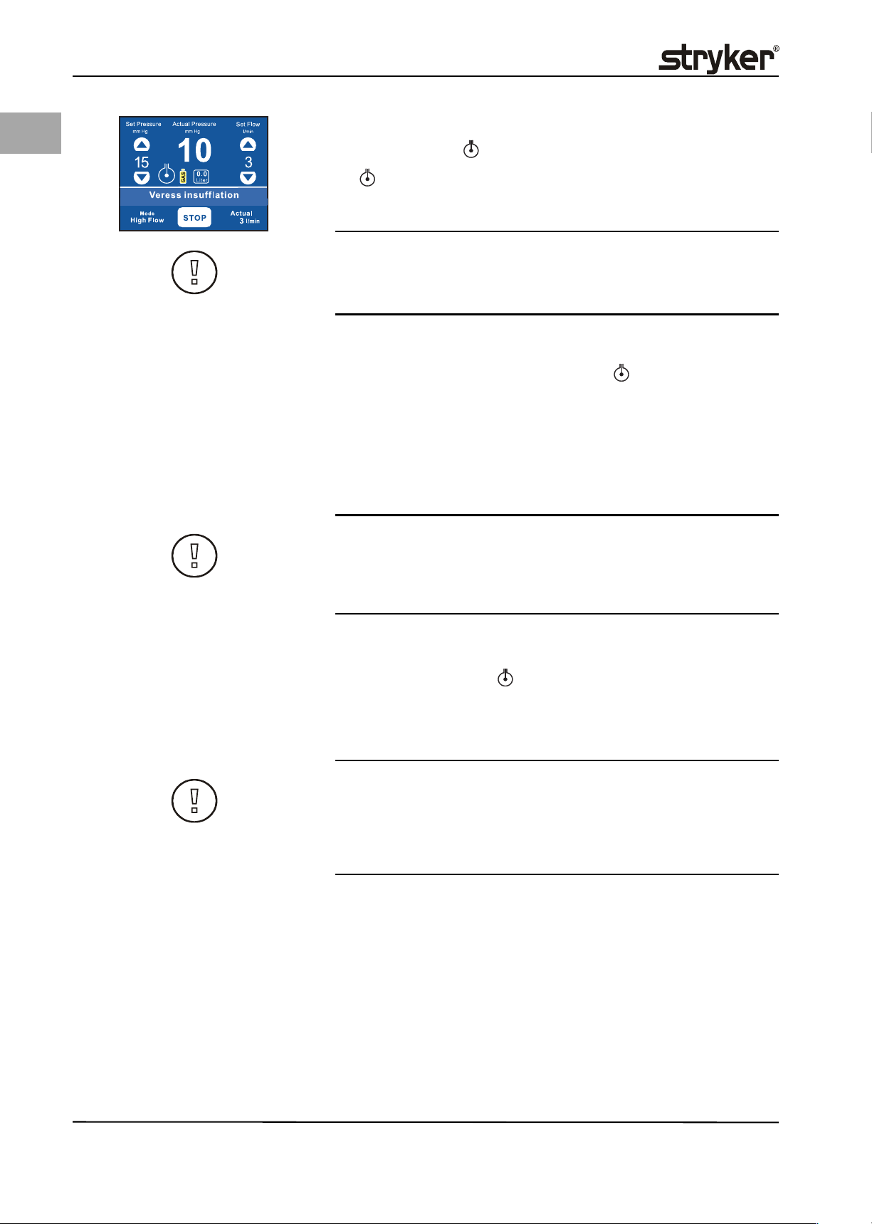
Press the START function field. The gas is automatically heated to 37 °C.
2. Stopping gas heating:
Press the STOP function field. Gas heating is switched off.
3. Pull the tube set plug from the device connection.
Operating the Device - General
Gas heating ON/OFF1. The gas heating is automatically started at the START of the insufflation:
EN
Incorrect/defective heating tubeWhen a defective heating tube set is used,
• the display depicts a crossed out symbol
HEATING
•the text line reads Gas heater defective <-> Call service,
• and an acoustic signal is emitted (3 short beeps).
Insufflation can be continued in this case, but the heating function is not available.
caused for exemple by external heat sources. If the temperature sensor measures a temperature >42°C, the status field of the display depicts Gas tempera-
ture >42 °C; 3 accoustic signals are emitted in addition, the HEATING symbol is
crossed out . Insufflation and the heating function are halted. After 3 seconds,
the display depicts Disconnect luer lock alternating with Cool down tube until
HEATING
the insufflation is manually restarted.
WARNING!
Unplug the cable of the heating tube from the device if the temperature sensor
measures a gas temperature exceeding >42 °C. Hot gas in the abdomen can lead
to serious injuries.
1. Disconnect the insufflation tube from the trocar or Veress needle.
2. Press the START function field. The device insufflates without heating the
gas.
3. Let hot gas escape until the tube is only warm to the touch and then reconnect the device again.
4. Continue surgery without gas heating.
Set Pressure
Actual Pressure
mm Hg
15
Gas heater defective
Change
Mode
mm Hg
0
0.0
Liter
GAS
START
HEATING
Set Flow
3
Actual
0
l/min
l/min
Gas temperature exceeds 42 °CThe device is equipped with a temperature sensor to protect against overheating,
Set Pressure
mm Hg
15
Actual Pressure
Cool down tube
Change
Mode
mm Hg
0
0.0
Liter
GAS
START
HEATING
Set Flow
Actual
0
l/min
3
l/min
and back on after approx. 10 seconds have expired. Gas heating is reactivated.
2. Should the error message be displayed again, you can continue using the device without gas heating by observing the risks for hypothermia.
3. Call an authorized service technician to check/fix the gas heating.
5.6.1 Using the direct pressure measurement function (Real-Time
Pressure Sensing RTP)
The insufflation tube sets "Heated tube set with Real-Time Pressure Sensing
(RTP)" and "High Flow tube set with Real-Time Pressure Sensing (RTP)" are
equipped with a sensor line which enables continuous measuring of the abdominal pressure. The insufflation line must be connected to one trocar and the measuring line (sensor line) to a second trocar. This set-up enables the PNEUMO SURE
XL High Flow Insufflator to directly measure the actual abdominal pressure while
in High Flow-, Pediatric- and Bariatric operating mode. The "Real-Time Pressure
Sensing" is deactivated during the Vessel Harvest operating mode. The use of an
insufflation tube without a second measurement/sensor line only allows the intermittent measuring of the pressure.
Insufflation is initially always started intermittently. Availability of the "Real-
Check gas heating after surgery1. Check gas heating after surgery using a different tube. Turn the device off
Pull apart at seam as
much as needed
at second trocar
at insufflation trocar
21
Page 28
EN
Operating the Device - General
Time Pressure Sensing" functionality is checked automatically. If this is the case,
the device switches to a continuous mode. This is indicated by the corresponding
symbol on the display:
The symbol is removed if continuous pressure measurement is currently not
possible or if insufflation is stopped.
CAUTION!
A closed, obstructed or disconnected pressure sensing line will disable the real-
time pressure sensing function. In this case the device will operate in the conventional intermittent insufflation mode.
Error detection and monitoring of the "RealTime Pressure Sensing (RTP)" function
The continuous pressure measurement function is verified during the initial device self check. Should a defect within the measuring system be detected, three
acoustic warning signals are emitted. The symbol is crossed out and the status line reads as follows: RTP defective / Call Service.
A detected defect within continuous pressure measurement does not generally
hinder use of the device, however without the RTP function. Disconnect the measuring channel and perform the surgery in the intermittent insufflation mode.
The acoustic warning on the defective RTP will be emitted with every activation/
deactivation of the insufflation as long as the pressure measurement function
remains defective.
CAUTION!
Do not attach a trocar to the pressure measurement / sensor line if the message
"RTP defective / Call Service" is displayed. Perform surgery only in the conven-
tional intermittent insufflation mode without using the real-time pressure sensing function.
In case of a closed sensor line or with pressure on the sensor or the insufflation
line during the initial device self check the real-time pressure sensing function
will not be activated and the will be crossed out. Three acoustic warning signals are emitted, the status line readsas follows: RTP deactivated. The device can
be operated in the conventional intermittent insufflation mode. In order to activate the RTP function the sensor line must be cleared, possible pressure released
and the device rebooted by turning it off and back on.
Leakage detection with function "RealTime Pressure Sensing (RTP)"
22
CAUTION!
When working with a tube set permitting the use of the RTP function, please
make sure that both lines are open upon activation of the device and there is
pressure neither on the sensor line nor on the insufflation line. Otherwise the
real-time pressure sensing function (RTP) will not be recognized and activated
during the initial device self check.
In case of an occlusion or a leakage in the sensor line during insufflation the device will automatically switch from the RTP operating mode into the conventional intermittent insufflation mode.
If the system detects a leak at the RTP connection regardless of the insufflation
mode:
• 2 long acoustic warning signal are emitted,
•the RTP symbol is no longer depicted,
• the message Check/change tube set is displayed,
• the usual intermittent pressure measuring is enabled again,
• the function of the occlusion detection is disabled.
Page 29
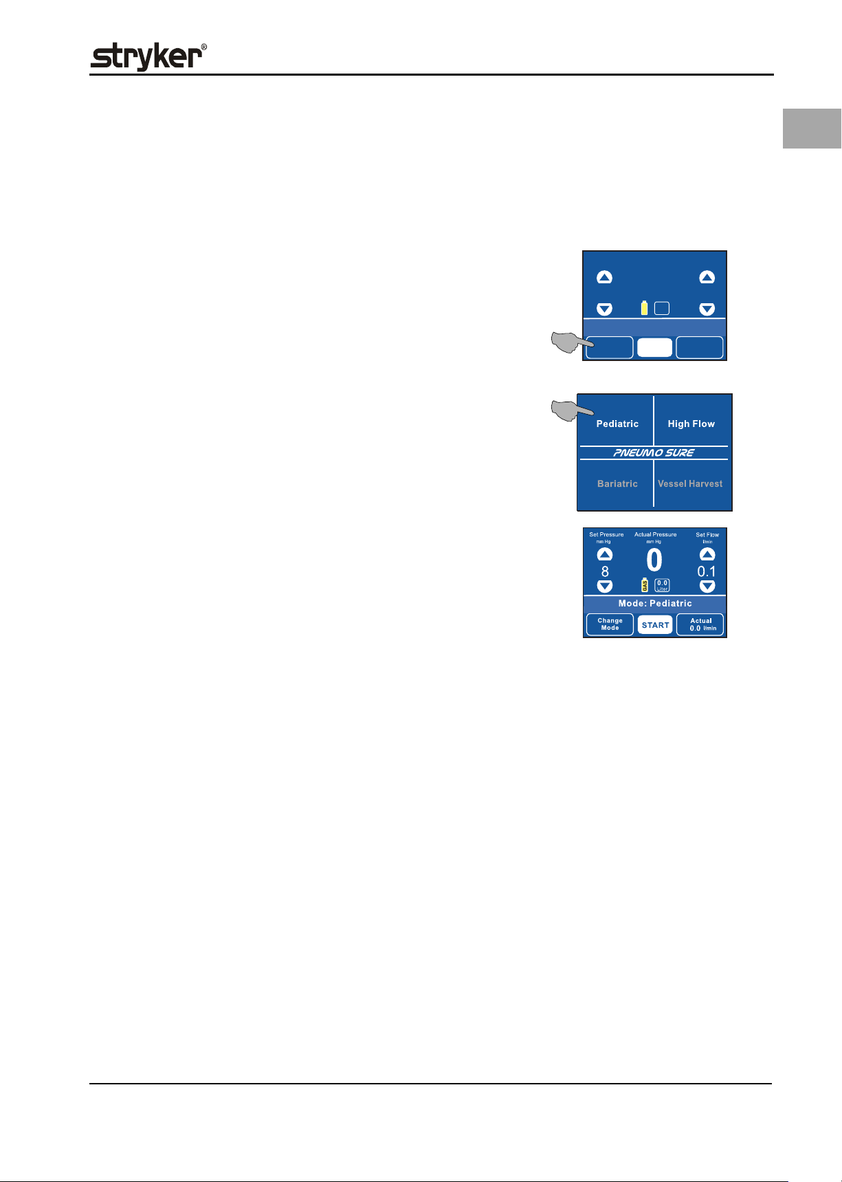
5.6.2 Displaying/Selecting Insufflation Operating Mode
The device can be equipped with up to 4 procedure modes. Procedure options can
be released or uploaded in different combinations depending on the order or
software upgrade.
PNEUMO SURE High Flow operating mode / Pediatric operating mode
PNEUMO SURE XL High Flow operating mode / Pediatric operating mode /
Bariatric operating mode / Vessel Harvest operating
mode
Set Pressure
mm Hg
Operating the Device - General
Actual Pressure
mm Hg
Set Flow
l/min
EN
1. Control or selection of the insufflation modes can be done only while insufflation is stopped. Press the function field for 2 s to change the insufflation
operating mode.
2. The display depicts an insufflation operating modes overview. Unavailable
operating modes are depicted in gray and cannot be selected. Press the respective function field to select the corresponding desired operating mode
(e.g. Pediatric).
3. After pressing the function field for the insufflation operating mode, the display depicts the selected procedure (e.g. Pediatric operating mode). The displayed parameters correspond with the factory settings or the values set in
the Configuration menu (see chapter 10.1 Configuration menu I, page 60).
5.6.3 Setting the Nominal Pressure - General
Press the function fields or on the display below the text line Set Pressure to
set the nominal pressure.
Applies to all modes:
• The nominal pressure can be increased or decreased during insufflation or
while insufflation is stopped.
• With every touch of the pressure function field or the nominal pressure is
increased/reduced in steps of 1 mm Hg. When pressing the pressure function
field or longer than 1,5 seconds, scrolling is activated but only up to the respective, application-dependent safety threshold. Once this limit has been
reached, the status line depicts the message Safety limit and the actual value
flashes. To allow settings above the safety threshold release the pressure function field for 2 seconds. The display switches back to the status display. Now it
is possible to increase the pressure above the safety threshold but only to the
next safety threshold (as far as existent) or to the maximum setting.
• The latest working settings are stored with interruption of the insufflation, but
only if the last value was below the lowest safety threshold (15 mm Hg for High
Flow and Bariatric operating mode, 12 mm Hg with Pediatric operating mode
and Vessel Harvest operating mode). Otherwise the set pressure value is reset
to the lowest safety threshold upon deactivation of insufflation.
• The latest settings are reset to the values preselected in the Configuration
menu when deactivating the device or when changing into the Configuration
menu or the Mode Selection menu. Upon choice of the respective working
mode the nominal settings as stored in the Configuration menu are displayed
(see chapter 10.1 Configuration menu I, page 60).
(1)
(2)
15
Mode: High Flow
Change
Mode
START
0
GAS
Actual
0
3
l/min
0.0
Liter
5.6.4 Setting the Nominal Flow - General
Press the function fields or on the display below the text line Set Flow to set
the nominal flow.
Applies to all modes:
23
Page 30
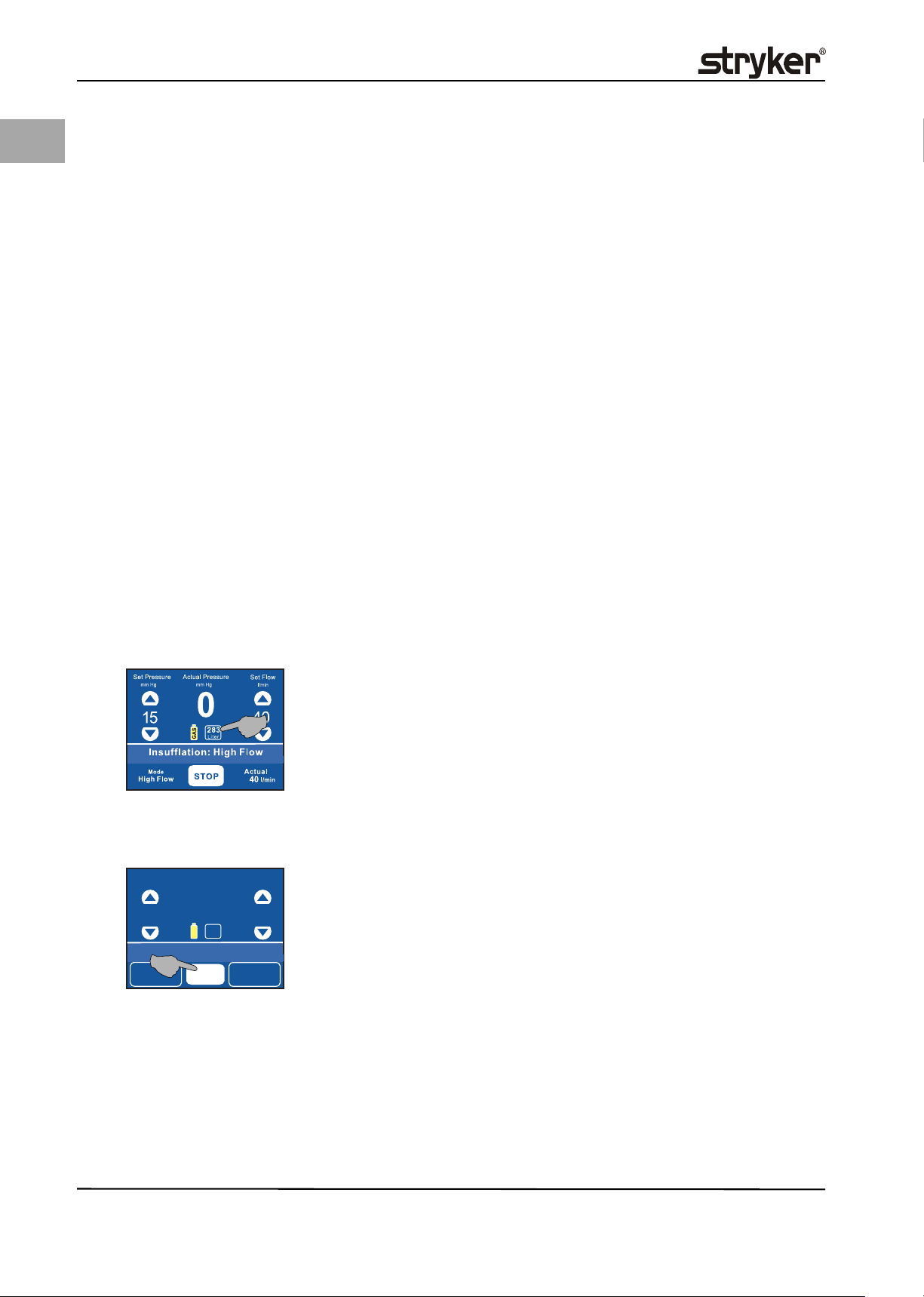
EN
Operating the Device - General
• The nominal flow can be increased or decreased during insufflation or while insufflation is stopped.
• With every touch of the flow function field or the nominal flow is increased/reduced in steps of 1 l/min. When working within the range of 0.1 to
1 l/min in Pediatric mode, the value is increased/reduced 0.1 l/min. When
pressing the flow function field or longer than 1.5 seconds, scrolling is ac-
tivated but only up to the respective, application-dependent safety threshold.
Once this limit has been reached, the status line depicts the message Safety
limit and the actual value flashes. To allow settings above the safety threshold
release the function field for 2 seconds. The display switches back to the status
display. Now it is possible to increase the flow above the safety threshold but
only to the next safety threshold (as far as existent) or to the maximum setting.
• The latest working settings are stored with interruption of the insufflation, but
only if the last value was below the lowest safety threshold (5l/min for Pedi-
atric operating mode and 6l/min for Vessel Harvest operating mode). Other-
wise the set flow value is reset to the lowest safety threshold upon
deactivation of insufflation.
• The latest settings are reset to the values preselected in the Configuration
menu when deactivating the device or when changing into the Configuration
menu or the Mode Selection menu. Upon choice of the respective working
mode the nominal settings as stored in the Configuration menu are displayed
(see chapter 10 Configuration Menu (Overview), page 58).
• The flow safety thresholds can be deactivated in the Configuration menu.
5.6.5 Gas Consumption Display
The gas consumption display depicts the insufflated volume of the gas in liters
since the last "resetting" of the display. The display indicates values between 0.0
liter and 9.9 liter in increments of 0.1 and between 10 liter to 999 liter in increments of 1.
Resetting the display The gas consumption display can be reset to 0.0 while insufflation is started as
well as stopped. Press the gas consumption display/function field to reset the gas
consumption display.
5.6.6 Starting/Stopping Insufflation
The START or STOP function field is displayed differently depending on operating
status.
Set Pressure
mm Hg
15
Mode: High Flow
Change
Mode
Actual Pressure
mm Hg
0
0.0
Liter
GAS
START
Set Flow
Actual
0
l/min
3
l/min
Start insufflation:
The START function field is displayed while insufflation is stopped. Press this field
to start insufflation.
The status display depicts the selected insufflation mode (e.g. Mode: High Flow).
The insufflation mode display depicts Change Mode.
Start insufflation by pressing the START function field.
24
Activated insufflation:
The status line depicts Insufflation and the name of the selected insufflation
mode (e.g. Insufflation: High Flow or Veress insufflation).
The frames around the insufflation mode display and the actual gas flow (menu
access) are hidden. This signals that these function fields are inactive during this
state.
Page 31

The insufflation mode display depicts the selected mode (e. g. Mode: High Flow).
Stop insufflation:
The STOP function field is displayed while insufflation is active.
Stop insufflation by pressing the STOP function field.
The status line depicts Insufflation stopped followed by the selected mode (e.g.
Insufflation: High Flow) alternating with Push to release. The insufflation
mode display depicts Change Mode.
In case the tube set connection is lost, the insufflation stops and the display depicts Insufflation stopped ->Mode: High Flow <->Tube not connected.
Operating the Device - General
EN
The device depicts the same message if a tube set has not been connected or has
not been inserted correctly and the START function field has been pressed. In this
case the insufflation will not be started. Please insert a tube set or check the tube
set connection.
5.6.7 Using the SIDNE Port (Optional)
The SIDNE Port allows connection to the SIDNE control system. When connected,
all of the functions and settings of the insufflator can be:
• controlled with SIDNE voice and pendant commands; and
• displayed on the SIDNE video overlay and pendant.
The physician(s) and support personnel must be thoroughly familiar with the setup and operation of the SIDNE. Please refer to the SIDNE documentation for the
proper setup, use and troubleshooting. When SIDNE is connected and active, the
functions and settings of the insufflator may simultaneously be adjusted using
the buttons on the front panel and the SIDNE.
5.6.8 Turning Device Off
Use the ON/OFF switch to turn the device off. The device is turned off.
25
Page 32

EN
Using and Controlling the PNEUMO SURE High Flow Insufflator in High Flow Mode
6 Using and Controlling the PNEUMO SURE High Flow Insuf-
flator in High Flow Mode
Intended use The PNEUMO SURE High Flow Insufflator serves to create a cavity by insufflating
CO2 during diagnostics and/or therapeutical laparoscopy. High Flow operating
mode is designed explicitly for laparoscopies performed on normal weight and
slightly obese (BMI < 30 kg/m
operating mode, the insufflator limits the pressure to max. 30 mm Hg and the
gas flow rate to max. 40 l/min. The device measures the pressure within the abdomen either continuously or at short intervals and constantly compares the
nominal with the actual abdominal pressure. The function of the device is to
maintain the nominal pressure. Any overpressure within the abdomen is lowered
to the preset nominal pressure by the automatic venting system.
Contraindications The device may not be used to fill an abdomen with CO2 if a laparoscopy is con-
traindicated. Please consult the manual of your laparoscope for absolute and relative contraindications. The device is not suitable for hysteroscopic insufflations,
i.e., it may not be used to distend the uterus.
The gas flow may not exceed 14 l/min when performing a laparoscopy on infants
or patients weighing less than 25 kilos.
2
) patients over the age of 14. While in High Flow
6.1 Device-Specific Dangers when Using the PNEUMO SURE High
Flow Insufflator in High Flow Operating Mode
WARNING!
Idiosyncratic reactions
Patients with sickle cell anemia or pulmonary insufficiency may have a higher
risk of metabolic imbalance related to excessive CO2 absorption (idiosyncratic
reaction).
WARNING!
CO2 absorption
CO2 is absorbed during insufflation (intravasation). This means the body absorbs
part of the CO2 gas used for insufflation. CO2 concentrations in the blood or re-
spiratory system that are too high can lead to death of the patient in extreme
cases. To lower this risk, always carefully and closely monitor the patient's vital
signs during the entire insufflation process and make sure patient is breathing
well. Sufficient respiration can help avoid or limit problems with CO2. High pressure or a high gas flow promotes CO2 absorption. The abdomen is sufficiently
distended using a pressure between 10 to 15 mm Hg. Pressure values above
15 mm Hg are required for only a few cases but do increase the risk of intravasation. Never exceed the max. intra-abdominal pressure of 30 mm Hg.
WARNING!
Metabolic and cardiac reactions
Insufflating CO2 may result in metabolic acidosis. This can lead to cardiac irregularities expressed with the following symptoms:
• Reduced respiration with restricted diaphram function
• Hypercapnia
• Reduction of venous reflux
• Reduced cardiac output
• Metabolic acidosis
26
WARNING!
Hypothermia/monitoring body temperature
The gas flow can lead to a lowering of the patient's body temperature during in-
sufflation. Hypothermia during insufflation can cause heart and cardiovascular
Page 33

Using and Controlling the PNEUMO SURE High Flow Insufflator in High Flow Mode
problems. The risk for hypothermia can be significantly reduced with the use of
gas that is pre-warmed to body temperature. Always monitor the patient's body
temperature during the entire insufflation. Make especially sure that the following, hypothermia promoting, surgical conditions are avoided as best as possible:
• High gas flow due to large leaks
• Long surgeries
• Use of cold (not preheated) irrigation and infusion solutions
WARNING!
Dehydration
Insufflation can lead to dehydration of the tissue. This can result in organ tissue
damage and cardiovascular reactions of the patient. Long surgeries and large
leaks increase the risk of dehydration (especially at the insertion points of the
trocars or when changing instruments).
WARNING!
Embolism
Improper placement of the insufflation instrument could cause insufflation of
gas into a vessel, resulting in air or CO2 embolisms. To reduce the risk of air or
CO2 embolism, perform initial insufflation at a low flow rate and ensure that the
insufflation instrument is correctly positioned. Check the position of the insufflation instrument immediately if the actual pressure rapidly reaches the nominal pressure value. CO2 embolisms can also be caused by a high intra-abdominal
pressure. Avoid high-pressure settings and close damaged blood vessels at once.
EN
WARNING!
Additional insufflation sources
The use of additional insufflation sources increases the intra-abdominal pressure. Continuously monitor intra-abdominal pressure over the course of the en-
tire insufflation if additional sources are used.
WARNING!
Please read the general risks and dangers information in chapter 2.1 Hazards,
page 5 and chapter 3.3 General Device-Inherent Dangers, page 8.
27
Page 34

Using and Controlling the PNEUMO SURE High Flow Insufflator in High Flow Mode
EN
(1)
Set Pressure
mm Hg
15
Mode: High Flow
Change
Mode
(2)
Actual Pressure
mm Hg
0
0.0
Liter
GAS
START
Set Flow
Actual
0
l/min
6.2 Selecting High Flow Insufflation Mode
1. Selection of the insufflation mode can be done only while insufflation is
stopped. If High Flow operating mode is not yet set and displayed, press the
function field Change Mode for 2 seconds to get the insufflation mode overview.
2. The display depicts the different insufflation operating modes that can be ac-
tivated. Select the desired insufflation operating mode by pressing the High
Flow function field. *Inactive operating modes are displayed in gray.
3. The procedure profile is depicted on the display. The displayed parameters
correspond with the factory settings or the values set in the Configuration
menu (see chapter 10.1 Configuration menu I, page 60).
3
l/min
Set Pressure
mm Hg
15
Mode: High Flow
Change
Mode
Actual Pressure
mm Hg
0
0.0
Liter
GAS
START
Set Flow
Actual
0
l/min
3
l/min
6.3 Presetting Nominal Pressure in High Flow Operating Mode
The nominal pressure can be set during insufflation or while insufflation is
stopped. Values may range from 1 to max. 30 mm Hg or the value set in the Configuration menu.
Increasing/decreasing nominal pressure:
Briefly press the or function field to increase or decrease the pressure. Keeping the or function field depressed longer than 1.5 seconds activates scrolling
in increments of 1.
Safety limit:
When increasing the nominal pressure, the status line of the display depicts Safety limit when reaching a value of 15 mm Hg. The nominal pressure 15 mm Hg is
a threshold value. This is where the recommended range for the intra-abdominal
pressure ends. Pressing the nominal pressure function field again does not increase the pressure any further. Release the function field for 2 seconds. Now you
can set a value up to 30 mm Hg.
CAUTION!
Exceeding this safety limit is to be decided by and the responsibility of the user/
operator.
28
6.4 Presetting Nominal Flow in High Flow Operating Mode
The nominal flow can be set during insufflation or while insufflation is stopped.
1. Briefly press the or function field to increase or decrease the flow. The
nominal flow can be increased from 1 to max. 40 l/min.
• Briefly press the corresponding field to set values in increments of 1.
Page 35

Using and Controlling the PNEUMO SURE High Flow Insufflator in High Flow Mode
• Keeping the or function field pressed longer than 1.5 seconds activates
scrolling through the gas flow rates 3, 20, 40 l/min or 40, 20, 3 l/min.
2. The preset values of the Configuration menu can be changed individually (see
chapter 10.1 Configuration menu I, page 60). Select a nominal gas flow between 1-40 l/min. The preset value is indicated in the nominal gas flow display. The values for the nominal gas flow refer to a device without connected
tube, filter, or instrument. Tube, filter, and instrument can reduce the gas
flow.
The device monitors the gas flow in two different operating modes depicted in
the status line with the following messages:
• Veress insufflation (1-5 l/min)
• Insufflation: High Flow (6-40 l/min)
Veress insufflation operating mode:
Veress insufflation is a gentle type of insufflation so that the actual pressure
does not exceed the preset pressure even in case of small volumes. To minimize
the risks in case of a faulty incision, the manufacturer recommends using Veress
insufflation to start a procedure (filling abdomen with CO2).
CAUTION!
Please note that the automatic venting system is not active during Veress insuf-
flation mode.
Set Pressure
mm Hg
15
Mode: High Flow
Change
Mode
Actual Pressure
mm Hg
0
0.0
Liter
GAS
START
Set Flow
Actual
0
l/min
EN
3
l/min
Insufflation: High Flow
While Insufflation: High Flow any pressure loss due to leaks can be quickly equalized. The APC Technology (Advanced Pressure Control) enables raising the actual
pressure gently to the level of the nominal pressure. In case of large volumes, the
actual pressure does not exceed the nominal pressure (see chapter 11 Safety
functions, page 70).
Start the device by pressing the START function field.
With a nominal flow setting of < 6 l/min Veress insufflation is displayed. Above
5l/min Insufflation: High Flow) is displayed.
Stop the device by pressing the STOP function field.
NOTE!
Tube, filter, and instrument can reduce the gas flow.
6.5 Performing the Function Test in High Flow Operating Mode
Check all the single-use/disposable items before removing them from the package to ensure that the packaging is intact and that the expiration date is still valid.
For your own safety and that of your patient, use only original accessories.
PreparationSterilize reusable instruments and tubing before surgery to prevent infections.
WARNING!
The function test must be performed prior to each surgical procedure.
29
Page 36

EN
Using and Controlling the PNEUMO SURE High Flow Insufflator in High Flow Mode
Testing the device
Fig. 6-1 Layout for testing the device
(1) ON/OFF switch
(2) Nominal pressure display
(3) START/STOP function field
(4) Gas consumption display
(5) Nominal flow display
(6) Insufflation tube set
(7) Stopcock (valve)
(8) Veress cannula
1. The device is switched off, no tube set is connected.
2. Make sure the gas supply is connected and open.
3. Use the ON/OFF switch (1) to turn the device on. The device conducts a device check.
4. Select High Insufflation operating mode in the insufflation mode selection.
5. Connect an original insufflation tube set (6) to the device.
6. Attach the insufflation tube to the Veress cannula (8).
7. Attach the stopcock (valve) to the Veress cannula (7).
8. If the gas consumption display function field does depict a value, press
the (4) function field to reset the display to 0.
9. Select the nominal pressure 15 mm Hg (2) and the gas flow 3 l/min (5).
10. Start insufflation: Press the START function field (3).
11. The display status line depicts Occlusion after max. 4 seconds.
12. Stop insufflation: Press the STOP function field (3).
(1) (2) (3) (4) (5) (6)
(8)
(7)
WARNING!
If the actual gas consumption is higher than 0.4 l, there is a leak in the system. If
this happens, use steps 13 to 15 outlined below to locate the leak.
13. Repeat items 7 to 11 without Veress cannula and with closed tube end. The
previously connected Veress cannula has a leak if gas consumption is now below 0.4 l.
14. Repeat items 8 to 12 without Veress cannula and without tube if another leak
becomes apparent. Close the end of the insufflation tube connection for this
test. If the gas consumption is then below 0.4 l, the previously used tube set
has a leak.
15. If another leak is detected, this leak is then directly within the device. Make
sure the device can no longer be operated until a qualified service technician
conducts the appropriate tests and repairs.
WARNING!
Never work with a leaky insufflation tube, accessory, and/or device. This can
lead to an incorrect measurement of the actual pressure values, which can cause
an uncontrolled pressure increase in the abdomen.
Testing gas heating functionality The functionality of the gas heating is indicated by displaying the gas heating
symbol on the display when using the "Heated tube set with RTP for Pneumo
30
Page 37

Using and Controlling the PNEUMO SURE High Flow Insufflator in High Flow Mode
Sure".
1. Connect the corresponding tube set ("Heated with Real-Time Pressure Sensing" or "High Flow with Real-Time Pressure Sensing").
2. Insufflation is initially always started intermittently. Availability of the "RealTime Pressure Sensing" functionality is checked automatically. If this is the
case, the device switches to a continuous mode. This is indicated by the corresponding symbol on the display.
6.5.1 Filling Tube System with CO2
At least 1 l of CO2 has to be let out from the system before every surgery while
the tube is connected and the end of the tube is open. This will expel any air within the tube system and the device.
1. Start insufflation: Press the START function field.
Wait until the gas consumption display shows 1.0 Liter.
2. Stop insufflation: Press the STOP function field.
3. Press the gas consumption display field to reset the gas consumption display
to 0.0 Liter. This ensures the gas consumption is correctly displayed during
surgery.
The function test is complete. The device is tested and ready to be used for surgery.
"Real-Time Pressure Sensing" functionality
(RTP)
EN
WARNING!
Do not use this device if a defect is suspected or detected during the function
check. This also applies to obvious defects, especially defects on the power plug
and power cable.
6.6 Using the Device during Surgery
WARNING!
The function test must be performed prior to each surgery.
CAUTION!
The venting system is automatically triggered (not during Veress mode and not
if the venting valve has been deactivated in the Configuration menu) if the measured actual pressure exceeds the set nominal pressure during insufflation. The
device interrupts insufflation and releases gas until the actual pressure has
dropped below the set nominal value.
1. The device is turned on.
2. An insufflation tube set is connected.
6.6.1 Insufflating with Veress Cannula
Using the device during surgery
On delivery from the factory, following values are set for High Flow operating
mode:
• a gas flow value of 3 l/min and
• Veress insufflation for insufflation through the Veress cannula.
CAUTION!
Up to 5 l/min Veress insufflation is set automatically. Please note that the automatic venting system is not active during Veress insufflation operating mode
(the venting valve is switched off automatically). The gas transport through the
31
Page 38

EN
Using and Controlling the PNEUMO SURE High Flow Insufflator in High Flow Mode
device is also specifically customized for use with a Veress cannula.
WARNING!
This manual does not include instructions for the safe use of the Veress cannula.
Only when you have ensured endoscopically that an aeroperitoneum can be gen-
erated, should a gas flow of more than 3 l/min and a pressure of more than
10 mm Hg be selected. Insert the Veress cannula into the abdomen. Check to see
if the Veress cannula is correctly positioned in the abdomen.
1. Attach the insufflation tube to the Veress cannula.
2. Select the desired nominal pressure and nominal gas flow.
3. Start insufflation: Press the START function field.
Check the actual pressure display and the gas consumption display.
6.6.2 Insufflating with the Trocar
1. Insert the trocar into the abdomen.
2. Connect the Luer Lock connection of the insufflation tube to the trocar.
3. Make sure the trocar is correctly positioned in the abdomen. Then select the
desired pressure and desired gas flow as intraoperative conditions.
4. The actual pressure display shows the current measured value for insufflation. As soon as this value approximates the selected nominal value, the gas
flow is automatically minimized. The gas consumption display shows the volume of gas consumed.
5. Check how the patient's body reacts to the selected pressure and gas flow
rate. Compare the abdominal filling rate to the selected nominal pressure.
You can change the nominal gas flow and the nominal pressure during surgery without interrupting the insufflation process.
6.6.3 "Real-Time Pressure Sensing" functionality (RTP)
To use the "Real-Time Pressure Sensing" (RTP) please use a tube set with measuring line. The Luer Lock connection of the measuring tube has to be connected to
another trocar placed during the surgery. This enables the continuous measuring
of the pressure (see 5.5 Connecting Insufflation Tube Set, page 19 and 5.6.1 Using
the direct pressure measurement function (Real-Time Pressure Sensing RTP),
page 21).
CAUTION!
Make sure the stopcock (valve) of the trocar is fully opened and that both tube
connections are connected to different trocars.
6.6.4 Stop the Insufflation
1. Press the STOP function field. The following values are displayed:
• Gas consumption display: last measured value
• Actual pressure: current measured value
• Actual gas flow: 0 l/min
• Nominal pressure: last set value In case of exceeding the safety limit, the
nominal pressure value will be reset to the safety limit value.
• Nominal gas flow: last set value
The status field of the display depicts Insufflation stopped followed by Mode:
High Flow alternating with Push to release.
2. Remove the tube set from the device. Observe applicable hygiene regulations
when disposing of the tube set.
32
CAUTION!
If the tube set remains connected to the device, there is the danger that leftover
Page 39

Using and Controlling the PNEUMO SURE High Flow Insufflator in High Flow Mode
fluid in the tube or the instruments will be sucked into the device.
3. Close the gas supply.
4. Use the ON/OFF switch to turn the device off.
NOTE!
Observe applicable hygiene regulations when disposing of the tube set.
EN
33
Page 40

EN
Using and Controlling the PNEUMO SURE High Flow Insufflator in Pediatric Operating Mode
7 Using and Controlling the PNEUMO SURE High Flow Insuf-
flator in Pediatric Operating Mode
Pediatric operating mode Pediatric operating mode is designed specifically for use on newborns, infants,
and children. While in Pediatric operating mode, the insufflator limits the pressure to max. 20mm Hg and the gas flow rate to max. 20l/min. When used on
children, the device should be set depending on the selected nominal flow and
the age and weight of the treated child as outlined in the table below:
Age Group Weight Flow Range
Children younger than 1 year approx. 1-9 kg 0.1 -0.5 l/min
Children between 1 and 3 years approx. 10-15 kg 0.5 -1.0 l/min
Children between 3 and 4 years approx. 16-19 kg 1.0 -2.0 l/min
Children between 4 and 14 years > 20 kg > 2.0 l/min
All children < 25 kg < 14.0 l/min
If the nominal flow is set too low, the nominal pressure cannot be reached. Check
for possible leaks. Due to the special operating method used during the Pediatric
application, the speed of equalizing the leak is slower than when using the High
Flow application (lower effective flow in the Pediatric application).
Contraindications The device may not be used to fill an abdomen with CO2 if a laparoscopy is con-
traindicated. Please consult the manual of your laparoscope for absolute and relative contraindications. The device is not suitable for hysteroscopic insufflations,
i.e., it may not be used to distend the uterus.
The gas flow may not exceed 14 l/min when performing a laparoscopy on infants
or patients weighing less than 25 kilos.
7.1 Device-Specific Dangers when Using the PNEUMO SURE High
Flow Insufflator in Pediatric Operating Mode
WARNING!
Only specially trained and qualified personnel may use this device on children or
for the endoscopic vessel harvesting procedure.
WARNING!
Gas flow limit
The gas flow may not exceed 14 l/min when performing a laparoscopy on new-
borns or patients weighing less than 25 kg (approx. 55 US pounds).
WARNING!
Recommended work settings
The flow values listed above for laparoscopic procedures performed on new-
borns, infants, and children are only suggested values. The selection of the suitable flow and pressure values is solely the responsibility of the attending
physician. However, adhering to the values listed above ensures an optimal performance of the Pediatrich operating mode of the insufflator.
34
WARNING!
Pneumolabium/pneumoscrotum
Children are at risk of a pneumolabium or pneumoscrotum.
Page 41

Using and Controlling the PNEUMO SURE High Flow Insufflator in Pediatric Operating Mode
WARNING!
Increased airway pressure
When laparoscopic procedures are performed on children, the increased intra-
abdominal pressure also increases the risk for higher airway pressures. Always
strictly monitor respiration and airway function when performing laparoscopic
procedures on children younger than 12 years of age.
WARNING!
Compression of the vena cava
When insufflating the abdomen of a child with medical CO2, an increased risk of
compressing the vena cava exists. This risk can be reduced by monitoring the systolic and diastolic blood pressure during the entire surgery.
WARNING!
Haemodynamic stability
A laparoscopy performed on children younger than 12 years of age can result in
the phenomenon of the increased CO2 content in the blood and with that to
problems of the haemodynamic system. It is recommended to increase the
breathing rate of the patient and to work with low flow values and pressure values not exceeding 12 mm Hg. The patient' circulatory system should be monitored at all times.
EN
WARNING!
Hypothermia
The insufflation gas flow usually drops significantly after the target pressure has
been reached and it is then only required to maintain the abdominal pressure.
However, leaks within the abdomen or the instrument can lead to a constant gas
flow of above 1 l/min. When operating on children younger than 12, a gas flow
of more than 1 l/min poses an increased risk of hypothermia for the patient. Corresponding measures to prevent hypothermia include the use of blankets or prewarmed gas. The patient' body temperature has to be monitored at all times
during surgery.
WARNING!
Device-inherent dangers
Please read the general risks and dangers information in chapter 2.1 Hazards,
page 5 and chapter 3.3 General Device-Inherent Dangers, page 8.
35
Page 42

Using and Controlling the PNEUMO SURE High Flow Insufflator in Pediatric Operating Mode
EN
(1)
(2)
7.2 Selecting Pediatric Operating Mode
1. Selection of the insufflation mode can be done only while insufflation is
stopped. If Pediatric operating mode is not yet set and displayed, press the
function field Change Mode for 2 seconds to get the insufflation mode overview.
2. The display depicts an insufflation modes overview. Select the desired insufflation operating mode by pressing the Pediatric function field.
3. The procedure profile is depicted on the display. The displayed parameters
correspond with the factory settings or the values set in the Configuration
menu (see chapter 10 Configuration Menu (Overview), page 58).
7.3 Presetting Nominal Pressure in Pediatric Operating Mode
The nominal pressure can be set during insufflation or while insufflation is
stopped. Values may range from 1 to max. 20 mm Hg or the value set in the Configuration menu.
Increasing/decreasing nominal pressure:
Briefly press the or function field to increase or decrease the pressure. Keeping the or function field depressed longer than 1.5 seconds activates scrolling
in increments of 1.
Select a nominal pressure value between 1 and 20 mm Hg. The preset value is indicated in the nominal pressure display.
Safety limit:
When increasing the nominal pressure, the status line of the display depicts Safety limit starting at 12 mm Hg and the nominal value flashes.
The nominal pressure value 12 mm Hg is a limit value and should not be exceeded for newborns if at all possible. Pressing the nominal pressure function field
again does not increase the pressure any further.
CAUTION!
Exceeding this safety limit is to be decided by and the responsibility of the user/
operator.
36
Release the function field at that point. The display switches back to the nominal
value setting after 2 seconds. Now you can set a value up to 15 mm Hg. The nominal pressure 15 mm Hg is a limit value. This is where the recommended range for
Page 43

Using and Controlling the PNEUMO SURE High Flow Insufflator in Pediatric Operating Mode
the intra-abdominal pressure ends. Pressing the nominal pressure ºfunction field
again does not increase the pressure any further. The status line of the display
depicts Safety limit and the nominal value flashes.
Release the function field at that point. The display switches back to the nominal
value setting after 2 seconds. Now you can set a value up to 20 mm Hg.
7.4 Presetting Nominal Flow in Pediatric Operating Mode
The nominal flow can be set during insufflation or while insufflation is stopped.
Reducing nominal gas flow:
Press the nominal gas flow function field to reduce the nominal gas flow. The
nominal gas flow is decreased in the range of
• 0.1 l/min to 2 l/min in increments of 0.1 l/min.
• 2 l/min to 20 l/min in increments of 1 l/min.
Keeping the function field depressed longer than 1.5 seconds activates scrolling.
• In the range of 0.1...2 l/min, rounding down to 1 or 0.1 l/min is applied.
• In the range of 2...20 l/min in increments of 1.
The nominal flow can be set during insufflation or while insufflation is stopped.
Set Pressure
Set Pressure
mm Hg
mm Hg
15
Change
Mode
Actual Pressure
Actual Pressure
mm Hg
mm Hg
0
283
Liter
GAS
Safety limit
Safety limit
START
Set Flow
Set Flow
0.1
Actual
0
l/min
l/min
l/min
EN
Increasing nominal gas flow:
Press the nominal gas flow function field to increase the nominal gas flow. The
nominal gas flow is increased in the range of
• 0.1 l/min to 2 l/min in increments of 0.1 l/min.
• 2 l/min to 20 l/min in increments of 1 l/min.
Keeping the function field depressed longer than 1.5 seconds activates scrolling.
• In the range of 0.1 l/min...<2 l/min, rounding up to 1 or 2 l/min is applied.
• Then in one-step increments down to 20 l/min.
Safety limit:
When increasing the nominal flow, the status line of the display depicts Safety
limit starting at 5 l/min and the nominal value flashes. (This safety limit can be
activated or deactivated in the Configuration menu).
Release the function field to increase the nominal gas flow further. The display
switches back to the nominal value setting after 2 seconds. Now you can set a
value of up to 20 l/min.
WARNING!
Exceeding this safety limit is to be decided by and the responsibility of the user/
operator.
37
Page 44

Using and Controlling the PNEUMO SURE High Flow Insufflator in Pediatric Operating Mode
EN
Veress insufflation operating mode:
The device monitors the gas flow in two different operating modes:
• Veress insufflation (≤ 1 l/min)
• Insufflation: Pediatric (> 1 l/min)
Veress insufflation Veress insufflation is intended for the gentle development of a pneumoperitone-
um. The nominal gas flow emitted by the device in this case is very low (in the
range of 0.1 l/min to 1 l/min).
To minimize the risks in case of a faulty incision, the manufacturer recommends
using Veress insufflation to start a procedure (filling abdomen with CO2).
Start the device by pressing the START function field.
CAUTION!
Please note that the automatic venting system is only active during the Veress
insufflation mode if "In Veress insufflation ON" has been set in the configuration
menu (only possible in Pediatric operating mode, see chapter 10 Configuration
Menu (Overview), page 58).
Venting system "In Veress insufflation OFF"
With a nominal flow setting of ≤ 1 l/min, Veress insufflation is displayed in the
status line after pressing the Start/Stop switch.
Above 1 l/min, Insufflation: Pediatric is displayed.
Venting system "In Veress insufflation ON"
With this setting, after pressing the START function field Insufflation: Pediatric is
displayed, even if the nominal flow is set to ≤ 1 l/min.
Insufflation: Pediatric While Insufflation: Pediatric any pressure loss due to leaks can be quickly equal-
ized. The APC Technology (Advanced Pressure Control) enables raising the actual
pressure gently to the level of the nominal pressure.
NOTE!
Tube, filter and instrument can reduce the gas flow.
7.5 Performing the Function Test in Pediatric Operating Mode be-
fore Using the Device during Surgery
Preparation Sterilize reusable instruments and tubing before surgery to prevent infections.
Check all the single-use/disposable items before removing them from the package to ensure that the packaging is intact and that the expiration date is still valid.
For your own safety and that of your patient, use only original accessories.
WARNING!
The function test must be performed prior to each surgical procedure.
38
Page 45

Using and Controlling the PNEUMO SURE High Flow Insufflator in Pediatric Operating Mode
(1) (2) (3) (4) (5) (6)
(8)
(7)
1. The device is switched off, no tube set is connected.
2. Make sure the gas supply is connected and open.
3. Use the ON/OFF switch (1) to turn the device on. The device conducts a device check.
4. Select Pediatric operating mode in the insufflation mode selection.
5. Connect an original insufflation tube set (6) to the device.
6. Attach the insufflation tube to the Veress cannula (8).
7. Attach the stopcock (valve) (7) to the Veress cannula.
8. If the gas consumption display function field does depict a value, press the
(4) function field to reset the display to 0.
9. Select the nominal pressure 8 mm Hg (2) and the gas flow 2 l/min (5).
10. Start insufflation: Press the START function field (3).
11. Insufflate for approx. 30 s. The display status line depicts Occlusion after max.
4 seconds.
12. Stop insufflation: Press the STOP function field (3).
Testing the device
EN
Fig. 7-1 Layout for testing the device
(1) ON/OFF switch
(2) Nominal pressure display
(3) START/STOP function field
(4) Gas consumption display
(5) Nominal flow display
(6) Insufflation tube set
(7) Stopcock (valve)
(8) Veress cannula
WARNING!
If the actual gas consumption is higher than 0.4 l, there is a leak in the system. If
this happens, use steps 13 to 15 outlined below to locate the leak.
13. Repeat items 7 to 11 without Veress cannula and with closed tube end. The
previously connected Veress cannula has a leak if gas consumption is now below 0.4 l.
14. Repeat items 8 to 12 without Veress cannula and without tube if another leak
becomes apparent. Close the end of the insufflation tube connection for this
test. If the gas consumption is then below 0.4 l, the previously used tube set
has a leak.
15. If another leak is detected, this leak is then directly within the device. Make
sure the device can no longer be operated until a qualified service technician
conducts the appropriate tests and repairs.
WARNING!
Never work with a leaky insufflation tube, accessory, and/or device. This can
lead to an incorrect measurement of the actual pressure values, which can cause
an uncontrolled pressure increase in the abdomen.
Testing gas heating functionalityThe functionality of the gas heating is indicated by displaying the gas heating
39
Page 46

EN
Using and Controlling the PNEUMO SURE High Flow Insufflator in Pediatric Operating Mode
symbol on the display when using the "Heated tube set with RTP for Pneumo
Sure".
"Real-Time Pressure Sensing" functionality
(RTP)
1. Connect the corresponding tube set ("Heated with Real-Time Pressure Sensing" or "High Flow with Real-Time Pressure Sensing").
2. Insufflation is initially always started intermittently. Availability of the "RealTime Pressure Sensing" functionality is checked automatically. If this is the
case, the device switches to a continuous mode. This is indicated by the corresponding symbol on the display.
7.5.1 Filling Tube System with CO2
At least 1 l of CO2 has to be let out from the system before every surgery while
the tube is connected and the end of the tube is open. This will expel any air within the tube system and the device.
1. Start insufflation: Press the START function field.
Wait until the gas consumption display shows 1.0 Liter.
2. Stop insufflation: Press the STOP function field.
3. Press the gas consumption display field to reset the gas consumption display
to 0.0 Liter. This ensures the gas consumption is correctly displayed during
surgery.
The function test is complete. The device is tested and ready to be used for surgery.
WARNING!
Do not use this device if a defect is suspected or detected during the function
check. This also applies to obvious defects, especially defects on the power plug
and power cable.
Using the device during surgery
7.6 Using the Device during Surgery
WARNING!
The function test must be performed prior to each surgery.
CAUTION!
The venting system is automatically triggered (not during Veress mode and not
if the venting valve has been deactivated in the Configuration menu) if the measured actual pressure exceeds the set nominal pressure during insufflation. The
device interrupts insufflation and releases gas until the actual pressure has
dropped below the set nominal value.
1. The device is turned on.
2. An insufflation tube set is connected.
7.6.1 Insufflating with Veress Cannula
On delivery from the factory, following values are set for Pediatric operating
mode:
• a gas flow value of 0.1 l/min and
• Veress insufflation for insufflation through the Veress cannula.
40
CAUTION!
Please note that with flow values up to 1 l/min the Veress insufflation operating
mode is automatically activated (the venting valve is switched off). The gas
Page 47

Using and Controlling the PNEUMO SURE High Flow Insufflator in Pediatric Operating Mode
transport is also specifically customized for use with a Veress cannula.
WARNING!
This manual does not include instructions for the safe use of the Veress cannula.
Only when you have ensured endoscopically that an aeroperitoneum can be gen-
erated, should a gas flow of more than 3 l/min and a pressure of more than
10 mm Hg be selected (see corresponding setting for children, chapter 3.1.2 Using Pediatric Operating Mode, page 7). Insert the Veress cannula into the abdomen. Check to see if the Veress cannula is correctly positioned in the abdomen.
1. Attach the insufflation tube to the Veress cannula.
2. Select the desired nominal pressure and nominal gas flow.
3. Start insufflation: Press the START function field.
Check the actual pressure display and the gas consumption display.
7.6.2 Insufflating with the Trocar
1. Insert the trocar into the abdomen.
2. Connect the Luer Lock connection of the insufflation tube to the trocar.
3. Make sure the trocar is correctly positioned in the abdomen. Then select the
desired pressure and desired gas flow as intraoperative conditions.
4. The actual pressure display shows the current measured value for insufflation. As soon as this value approximates the selected nominal value, the gas
flow is automatically minimized. The gas consumption display shows the volume of gas consumed.
5. Check how the patient's body reacts to the selected pressure and gas flow
rate. Compare the abdominal filling rate to the selected nominal pressure.
You can change the nominal gas flow and the nominal pressure during surgery without interrupting the insufflation process.
EN
7.6.3 "Real-Time Pressure Sensing" functionality (RTP)
To use the "Real-Time Pressure Sensing" (RTP) please use a tube set with measuring line. The Luer Lock connection of the measuring tube has to be connected to
another trocar placed during the surgery. This enables the continuous measuring
of the pressure (see 5.5 Connecting Insufflation Tube Set, page 19 and 5.6.1 Using
the direct pressure measurement function (Real-Time Pressure Sensing RTP),
page 21).
CAUTION!
Make sure the stopcock (valve) of the trocar is fully opened and that both tube
connections are connected to different trocars.
7.6.4 Stop the Insufflation
1. Press the STOP function field. The following values are displayed:
• Gas consumption display: last measured value
• Actual pressure: current measured value
• Actual gas flow: 0 l/min
• Nominal pressure: last set value In case of exceeding the safety limit, the
nominal pressure value will be reset to the lowest safety limit value.
• Nominal gas flow: last set value In case of exceeding the safety limit, the
nominal flow value will be reset to the safety limit value (only if activated).
The status field of the display depicts Insufflation stopped followed by
Mode: Pediatric alternating with Push to release.
2. Remove the tube set from the device. Observe applicable hygiene regulations
41
Page 48

EN
Using and Controlling the PNEUMO SURE High Flow Insufflator in Pediatric Operating Mode
when disposing of the tube set.
CAUTION!
If the tube set remains connected to the device, there is the danger that leftover
fluid in the tube or the instruments will be sucked into the device.
3. Close the gas supply.
4. Use the ON/OFF switch to turn the device off.
NOTE!
Observe applicable hygiene regulations when disposing of the tube set.
42
Page 49

Using and Controlling the PNEUMO SURE XL High Flow Insufflator in Bariatric Operating Mode
8 Using and Controlling the PNEUMO SURE XL High Flow In-
sufflator in Bariatric Operating Mode
weight (BMI>30kg/m2) adults. While in Bariatric mode, the insufflator limits
the pressure to max. 30 mm Hg and the gas flow to max. 45 l/min. This operating
mode delivers rapid insufflation of large volumes.
traindicated. Please consult the manual of your laparoscope for absolute and relative contraindications. The device is not suitable for hysteroscopic insufflations,
i.e., it may not be used to distend the uterus.
The gas flow may not exceed 14 l/min when performing a laparoscopy on infants
or patients weighing less than 25 kilos.
EN
Intended useBariatric operating mode is used for laparoscopies performed on severely over-
ContraindicationsThe device may not be used to fill an abdomen with CO2 if a laparoscopy is con-
8.1 Device-Specific Dangers when Using the PNEUMO SURE High
Flow Insufflator in Bariatric Operating Mode
WARNING!
Altered Respiratory Physiology
Always monitor the patient's respiratory functions during the entire surgery. The
larger body mass supported by the thoracic cage and the larger amount of fat in
the abdominal cavity may reduce the elasticity of the thoracic wall. In addition,
the increased intra-abdominal pressure secondary to insufflation may alter the
normal physiological lung parameters thus resulting in a reduction of the functional lung volume. Shallow, rapid breathing is symptomatic of this condition.
Even modest physical stress causes a tremendous increased demand for oxygen,
which stands in contrast to the ineffective respiratory musculature that requires
more oxygen because it must overcome the reduced elasticity of the thoracic
cage. The functional capacity of the lungs is small and even moderate stress can
lead to respiratory failure.
WARNING!
Subcutaneous Emphysema
When puncturing the thicker abdominal wall of morbidly obese patients with
the Veress cannula or the trocar, carefully monitor the correct position of the instrument in the abdomen.
WARNING!
Idiosyncratic reactions
Patients with sickle cell anemia or pulmonary insufficiency may have a higher
risk of metabolic imbalance related to excessive CO2 absorption (idiosyncratic
reaction).
WARNING!
CO2 absorption
CO2 is absorbed during insufflation (intravasation). This means the body absorbs
part of the CO2 gas used for insufflation. CO2 concentrations in the blood or respiratory system that are too high can lead to death of the patient in extreme
cases. To lower this risk, always carefully and closely monitor the patient's vital
signs during the entire insufflation process and make sure patient is breathing
well. Sufficient respiration can help avoid or limit problems with CO2. High pressure or a high gas flow promotes CO2 absorption. The abdomen is sufficiently
distended using a pressure between 10 to 15 mm Hg. Pressure values above
15 mm Hg are required for only a few cases but do increase the risk of intravasation. Never exceed the max. intra-abdominal pressure of 30 mm Hg.
43
Page 50

EN
Using and Controlling the PNEUMO SURE XL High Flow Insufflator in Bariatric Operating Mode
WARNING!
CO2 supersaturation
To avoid generating CO2 supersaturation, an increased level of respiratory activ-
ity is required. An overweight patient's oxygen demand and carbon dioxide production are greater and increase faster under physical stress than do those of
patients with normal body weight.
WARNING!
Heart and cardiovascular insufficiency
Constantly monitor all heart and cardiovascular parameter during surgery since
morbidly obese patients have an increased risk of heart and cardiovascular insufficiencies.
WARNING!
Metabolic and cardiac reactions
Insufflating CO2 may result in metabolic acidosis. This can lead to cardiac irreg-
ularities expressed with the following symptoms:
• Reduced respiration with restricted diaphram function
• Hypercapnia
• Reduction of venous reflux
• Reduced cardiac output
• Metabolic acidosis
WARNING!
Hypothermia/monitoring body temperature
The gas flow can lead to a lowering of the patient's body temperature during insufflation. Hypothermia during insufflation can cause heart and cardiovascular
problems. The risk for hypothermia can be significantly reduced with the use of
gas that is pre-warmed to body temperature. Always monitor the patient's body
temperature during the entire insufflation. Make especially sure that the following, hypothermia promoting, surgical conditions are avoided as best as possible:
• High gas flow due to large leaks
• Long surgeries
• Use of cold (not preheated) irrigation and infusion solutions
WARNING!
Dehydration
Insufflation can lead to dehydration of the tissue. This can result in organ tissue
damage and cardiovascular reactions of the patient. Long surgeries and large
leaks increase the risk of dehydration (especially at the insertion points of the
trocars or when changing instruments).
44
Page 51

Using and Controlling the PNEUMO SURE XL High Flow Insufflator in Bariatric Operating Mode
WARNING!
Embolism
Improper placement of the insufflation instrument could cause insufflation of
gas into a vessel, resulting in air or CO2 embolisms. To reduce the risk of air or
CO2 embolism, perform initial insufflation at a low flow rate and ensure that the
insufflation instrument is correctly positioned. Check the position of the insufflation instrument immediately if the actual pressure rapidly reaches the nominal pressure value. CO2 embolisms can also be caused by a high intra-abdominal
pressure. Avoid high-pressure settings and close damaged blood vessels at once.
WARNING!
Additional insufflation sources
The use of additional insufflation sources increases the intra-abdominal pres-
sure. Continuously monitor intra-abdominal pressure over the course of the entire insufflation if additional sources are used.
WARNING!
Device-inherent dangers
Please read the general risks and dangers information in chapter 2.1 Hazards,
page 5 and chapter 3.3 General Device-Inherent Dangers, page 8.
EN
8.2 Selecting Bariatric Operating Mode
1. Selection of the insufflation mode can be done only while insufflation is
stopped. If Bariatric operating mode is not yet set and displayed, press the
function field Change Mode for 2 seconds to get the insufflation mode overview.
2. The display depicts an insufflation modes overview. Select the desired insufflation operating mode by pressing the Bariatric function field. *Inactive operating modes are displayed in gray.
3. The procedure profile is depicted on the display. The displayed parameters
correspond with the factory settings or the values set in the Configuration
menu (see chapter 10.1 Configuration menu I, page 60).
(1)
(2)
Set Pressure
mm Hg
15
Mode: High Flow
Change
Mode
Actual Pressure
mm Hg
0
0.0
Liter
GAS
START
Set Flow
Actual
0
l/min
3
l/min
45
Page 52

EN
Using and Controlling the PNEUMO SURE XL High Flow Insufflator in Bariatric Operating Mode
8.3 Presetting Nominal Pressure in Bariatric Operating Mode
The nominal pressure can be set during insufflation or while insufflation is
stopped. Values may range from 1 to max. 30 mm Hg or the value set in the Configuration menu.
Increasing/decreasing nominal pressure:
Briefly press the or function field to increase or decrease the pressure. Keeping the or function field depressed longer than 1.5 seconds activates scrolling in increments of 1.
Safety limit:
When increasing the nominal pressure, the status line of the display depicts Safety limit starting at 15 mm Hg and the nominal value flashes. The nominal pres-
sure 15 mm Hg is a threshold value. This is where the recommended range for
the intra-abdominal pressure ends. Pressing the nominal pressure function
field again does not increase the pressure any further. Release the function field
at that point. The display switches back to the nominal value setting after 2 seconds. Now you can set a value up to 30 mm Hg.
CAUTION!
Exceeding this safety limit is to be decided by and the responsibility of the user/
operator.
8.4 Presetting Nominal Flow in Bariatric Operating Mode
The nominal flow can be increased or decreased during insufflation or while insufflation is stopped.
1. Briefly press the or function field to increase or decrease the flow. The
nominal flow can be increased from 1 to max. 45 l/min.
• Briefly press the corresponding field to set values in increments of 1.
• Keeping the or function field pressed longer than 1.5 seconds activates
scrolling through the gas flow rates 5, 25, 45 l/min or 45, 25, 5 l/min.
2. The preset values of the Configuration menu can be changed individually (see
chapter 10.1 Configuration menu I, page 60). Select a nominal gas flow between 1-45 l/min. The preset value is indicated in the nominal gas flow display. The values for the nominal gas flow refer to a device without connected
tube, filter, or instrument. Tube, filter, and instrument can reduce the gas
flow.
The device monitors the gas flow in two different operating modes:
• Veress insufflation (1-5 l/min)
• Insufflation: Bariatric (6-45 l/min)
46
Veress insufflation operating mode:
Veress insufflation is a gentle type of insufflation so that the actual pressure
does not exceed the preset pressure even in case of small volumes. To minimize
the risks in case of a faulty incision, the manufacturer recommends using Veress
insufflation to start a procedure (filling abdomen with CO2).
WARNING!
Please note that the automatic venting system is not active during Veress insuf-
flation mode.
Page 53

Using and Controlling the PNEUMO SURE XL High Flow Insufflator in Bariatric Operating Mode
Insufflation: Bariatric
While Insufflation: Bariatric any pressure loss due to leaks can be quickly equalized. The APC Technology (Advanced Pressure Control) enables raising the actual
pressure gently to the level of the nominal pressure. In case of large volumes, the
actual pressure does not exceed the nominal pressure (see chapter 11 Safety
functions, page 70).
Start the device by pressing the START function field.
With a nominal flow setting of < 6 l/min Veress insufflation is displayed. Above
5l/min Insufflation: Bariatric is displayed.
Stop the device by pressing the STOP function field.
NOTE!
Tube, filter and instrument can reduce the gas flow.
EN
8.5 Performing the Function Test in Bariatric Operating Mode before
Using the Device during Surgery
Check all the single-use/disposable items before removing them from the package to ensure that the packaging is intact and that the expiration date is still valid.
For your own safety and that of your patient, use only original accessories.
WARNING!
The function test must be performed prior to each surgical procedure.
(1) (2) (3) (4) (5) (6)
PreparationSterilize reusable instruments and tubing before surgery to prevent infections.
Testing the device
Fig. 8-1 Layout for testing the device
(1) ON/OFF switch
(2) Nominal pressure display
(3) START/STOP function field
(4) Gas consumption display
(5) Nominal flow display
(6) Insufflation tube set
(7) Stopcock (valve)
(8) Veress cannula
(8)
(7)
1. The device is switched off, no tube set is connected.
2. Make sure the gas supply is connected and open.
3. Use the ON/OFF switch (1) to turn the device on. The device conducts a de-
47
Page 54

EN
Using and Controlling the PNEUMO SURE XL High Flow Insufflator in Bariatric Operating Mode
vice check.
4. Select Bariatric operating mode in the insufflation mode selection.
5. Connect an original insufflation tube set (6) to the device.
6. Attach the insufflation tube to the Veress cannula (8).
7. Attach the stopcock (valve) (7) to the Veress cannula.
8. If the gas consumption display function field does depict a value, press the
(4) function field to reset the display to 0.
9. Select the nominal pressure 15 mm Hg (2) and the gas flow 5 l/min (5).
10. Start insufflation: Press the START function field (3).
11. Insufflate for approx. 30 s. The display status line depicts Occlusion after max.
4 seconds.
12. Stop insufflation: Press the STOP function field (3).
WARNING!
If the actual gas consumption is higher than 0.4 l, there is a leak in the system. If
this happens, use steps 13 to 15 outlined below to locate the leak.
13. Repeat items 7 to 11 without Veress cannula and with closed tube end. The
previously connected Veress cannula has a leak if gas consumption is now below 0.4 l.
14. Repeat items 8 to 12 without Veress cannula and without tube if another leak
becomes apparent. Close the end of the insufflation tube connection for this
test. If the gas consumption is then below 0.4 l, the previously used tube set
has a leak.
15. If another leak is detected, this leak is then directly within the device. Make
sure the device can no longer be operated until a qualified service technician
conducts the appropriate tests and repairs.
WARNING!
Never work with a leaky insufflation tube, accessory, and/or device. This can
lead to an incorrect measurement of the actual pressure values, which can cause
an uncontrolled pressure increase in the abdomen.
Testing gas heating functionality The functionality of the gas heating is indicated by displaying the gas heating
symbol on the display when using the "Heated tube set with RTP for Pneumo
Sure".
"Real-Time Pressure Sensing" functionality
(RTP)
1. Connect the corresponding tube set ("Heated with Real-Time Pressure Sensing" or "High Flow with Real-Time Pressure Sensing").
2. Insufflation is initially always started intermittently. Availability of the "RealTime Pressure Sensing" functionality is checked automatically. If this is the
case, the device switches to a continuous mode. This is indicated by the corresponding symbol on the display.
8.5.1 Filling Tube System with CO2
At least 1 l of CO2 has to be let out from the system before every surgery while
the tube is connected and the end of the tube is open. This will expel any air within the tube system and the device.
1. Start insufflation: Press the START function field.
Wait until the gas consumption display shows 1.0 Liter.
2. Stop insufflation: Press the STOP function field.
3. Press the gas consumption display field to reset the gas consumption display
to 0.0 Liter. This ensures the gas consumption is correctly displayed during
surgery.
48
The function test is complete. The device is tested and ready to be used for surgery.
Page 55

Using and Controlling the PNEUMO SURE XL High Flow Insufflator in Bariatric Operating Mode
WARNING!
Do not use this device if a defect is suspected or detected during the function
check. This also applies to obvious defects, especially defects on the power plug
and power cable.
8.6 Using the Device during Surgery
WARNING!
The function test must be performed prior to each surgery.
CAUTION!
The venting system is automatically triggered (not during Veress mode and not
if the venting valve has been deactivated in the Configuration menu) if the measured actual pressure exceeds the set nominal pressure during insufflation. The
device interrupts insufflation and releases gas until the actual pressure has
dropped below the set nominal value.
1. The device is turned on.
2. An insufflation tube set is connected.
EN
Using the device during surgery
8.6.1 Insufflating with Veress Cannula
On delivery from the factory, following values are set for Bariatric operating
mode:
• a gas flow value of 5 l/min and
• Veress insufflation for insufflation through the Veress cannula.
CAUTION!
Please note that with flow values up to 5 l/min the Veress insufflation operating
mode is automatically activated (the venting valve is switched off). The gas
transport is also specifically customized for use with a Veress cannula.
WARNING!
This manual does not include instructions for the safe use of the Veress cannula.
Only when you have ensured endoscopically that an aeroperitoneum can be generated, should a gas flow of more than 3 l/min and a pressure of more than
10 mm Hg be selected. Insert the Veress cannula into the abdomen. Check to see
if the Veress cannula is correctly positioned in the abdomen.
1. Attach the insufflation tube to the Veress cannula.
2. Select the desired nominal pressure and nominal gas flow.
3. Start insufflation: Press the START function field.
Check the actual pressure display and the gas consumption display.
8.6.2 Insufflating with the Trocar
1. Insert the trocar into the abdomen.
2. Connect the Luer Lock connection of the insufflation tube to the trocar.
3. Make sure the trocar is correctly positioned in the abdomen. Then select the
desired pressure and desired gas flow as intraoperative conditions.
4. The actual pressure display shows the current measured value for insufflation. As soon as this value approximates the selected nominal value, the gas
flow is automatically minimized. The gas consumption display shows the volume of gas consumed.
5. Check how the patient's body reacts to the selected pressure and gas flow
49
Page 56

EN
Using and Controlling the PNEUMO SURE XL High Flow Insufflator in Bariatric Operating Mode
rate. Compare the abdominal filling rate to the selected nominal pressure.
You can change the nominal gas flow and the nominal pressure during surgery without interrupting the insufflation process. The Luer Lock connection
of the measuring tube can be connected to another trocar that also inserted
when using a tube set with measuring line. This enables the continuous measuring of the pressure.
8.6.3 "Real-Time Pressure Sensing" functionality (RTP)
To use the "Real-Time Pressure Sensing" (RTP) please use a tube set with measuring line. The Luer Lock connection of the measuring tube has to be connected to
another trocar placed during the surgery. This enables the continuous measuring
of the pressure (see 5.5 Connecting Insufflation Tube Set, page 19 and 5.6.1 Using
the direct pressure measurement function (Real-Time Pressure Sensing RTP)).
CAUTION!
Make sure the stopcock (valve) of the trocar is fully opened and that both tube
connections are connected to different trocars.
8.7 Stop the Insufflation
1. Press the STOP function field. The following values are displayed:
• Gas consumption display: last measured value
• Actual pressure: current measured value
• Actual gas flow: 0 l/min
• Nominal pressure: last set value In case of exceeding the safety limit, the
nominal pressure value will be reset to the safety limit value.
• Nominal gas flow: last set value
The status field of the display depicts Insufflation stopped followed by
Mode: Bariatric alternating with Push to release.
2. Remove the tube set from the device. Observe applicable hygiene regulations
when disposing of the tube set.
CAUTION!
If the tube set remains connected to the device, there is the danger that leftover
fluid in the tube or the instruments will be sucked into the device.
3. Close the gas supply.
4. Use the ON/OFF switch to turn the device off.
NOTE!
Observe applicable hygiene regulations when disposing of the tube set.
50
Page 57

Using and Controlling the PNEUMO SURE XL High Flow Insufflator in Vessel Harvest Operating Mode
9 Using and Controlling the PNEUMO SURE XL High Flow In-
sufflator in Vessel Harvest Operating Mode
medical-grade CO2 when harvesting vessels (veins and arteries) during a minimally invasive procedure within the scope of heart bypass surgery. While in Ves-
sel Harvest operating mode, the insufflator limits the pressure to max.
20 mm Hg and the gas flow rate to max. 10 l/min. Surgery to harvest vessels requires the use of a special instrument.
cal application is contraindicated. Please consult the manual of that instrument
for additional information and special application indications.
9.1 Device-Specific Dangers when Using the PNEUMO SURE XL High
Flow Insufflator in Vessel Harvest Operating Mode
WARNING!
Only specially trained and qualified personnel may use this device on children or
for the endoscopic vessel harvesting procedure.
WARNING!
Before using the insufflator to endoscopic harvest vessels, please check whether
the used instrument is intended for CO2 insufflation.
EN
Intended useVessel Harvest operating mode is designed for the controlled insufflation of
ContraindicationsThe device may not be used for the endoscopic harvesting of vessels if this surgi-
WARNING!
Pneumoperitoneum
When a vessel is harvested from the leg of a patient with a perforated groin, it is
possible for CO2 to reach the abdomen and cause a pneumoperitoneum. Make
sure the abdomen does not fill with CO2 during surgery.
WARNING!
Idiosyncratic reactions
Patients with sickle cell anemia or pulmonary insufficiency may have a higher
risk of metabolic imbalance related to excessive CO2 absorption (idiosyncratic
reaction).
WARNING!
CO2 absorption
Due to the special surgical procedures - start of the heart bypass operation, and
the endoscopic removal of the vessel - special care has to be taken as CO2 is always absorbed through the tissue of the patient during insufflation (intravasation). This means the body absorbs part of the CO2 gas used for insufflation. CO2
concentrations in the blood or respiratory system that are too high can lead to
death of the patient in extreme cases. To lower this risk, always carefully and
closely monitor the patient's vital signs during the entire insufflation process
and make sure patient is breathing well. Sufficient respiration can help avoid or
limit problems with CO2. High pressure or a high gas flow promotes CO2 absorption.
WARNING!
Metabolic and cardiac reactions
Due to the special surgical conditions - start of the heart bypass surgery and ves-
sel harvesting - it is especially important to remember the existing risk of metabolic acidosis when insufflating with CO2. This can lead to cardiac irregularities
51
Page 58

EN
Using and Controlling the PNEUMO SURE XL High Flow Insufflator in Vessel Harvest Operating Mode
expressed with the following symptoms:
• Reduced respiration with restricted diaphram function
• Hypercapnia
• Reduction of venous reflux
• Reduced cardiac output
• Metabolic acidosis
WARNING!
Dehydration
Insufflation can lead to dehydration of the tissue. This can result in organ tissue
damage and cardiovascular reactions of the patient. Long surgeries and large
leaks increase the risk of dehydration (especially at the insertion points of the
trocars or when changing instruments).
WARNING!
Embolism
Improper placement of the insufflation instrument could cause insufflation of
gas into a vessel, resulting in air or CO2 embolisms. To reduce the risk of air or
CO2 embolism, perform initial insufflation at a low flow rate and ensure that the
insufflation instrument is correctly positioned. Check the position of the insufflation instrument immediately if the actual pressure rapidly reaches the nominal pressure value. CO2 embolisms can also be caused by a high pressure. Avoid
high-pressure settings and close damaged blood vessels at once.
(1)
WARNING!
Device-inherent dangers
Please read the general risks and dangers information in chapter 2.1 Hazards,
page 5 and chapter 3.3 General Device-Inherent Dangers, page 8.
9.2 Selecting Vessel Harvest Operating Mode
1. Selection of the insufflation mode can be done only while insufflation is
stopped. If Vessel Harvest operating mode is not yet set and displayed, press
the function field Change Mode for 2 seconds to get the insufflation mode
overview.
2. The display depicts an insufflation modes overview. Select the desired insufflation operating mode by pressing the Vessel Harvest function field.
(2)
3. The procedure profile is depicted on the display. The displayed parameters
correspond with the factory settings or the values set in the Configuration
menu (see chapter 10.1 Configuration menu I, page 60).
52
Page 59

Using and Controlling the PNEUMO SURE XL High Flow Insufflator in Vessel Harvest Operating Mode
9.3 Presetting Nominal Pressure in Vessel Harvest Operating Mode
The nominal pressure can be set during insufflation or while insufflation is
stopped. Values may range from 1 to max. 20 mm Hg or the value set in the Con-
figuration menu.
Increasing/decreasing nominal pressure:
Briefly press the or function field to increase or decrease the pressure. Keeping the or function field depressed longer than 1.5 seconds activates scrolling
in increments of 1.
Safety limit:
When increasing the nominal pressure, the status line of the display depicts Safety limit starting at 12 mm Hg and the nominal value flashes.
The nominal pressure value 12 mm Hg is a limit value and should not be exceeded when performing vessel harvesting surgery. Pressing the nominal pressure
function field again does not increase the pressure any further.
CAUTION!
Exceeding this safety limit is to be decided by and the responsibility of the user/
operator.
EN
Release the function field at that point. The display switches back to the nominal
value setting after 2 seconds. Now you can set a value up to 15 mm Hg.
The Safety limit message is re-displayed in the status line starting at 15 mm Hg
and the nominal value flashes.
The nominal pressure value 15 mm Hg is a limit value and should not be exceeded when performing vessel harvesting surgery. Pressing the nominal pressure
function field again does not increase the pressure any further.
CAUTION!
Exceeding this safety limit is to be decided by and the responsibility of the user/
operator.
Release the function field at that point. The display switches back to the nominal
value setting after 2 seconds. Now you can set a value up to 20 mm Hg.
53
Page 60

Using and Controlling the PNEUMO SURE XL High Flow Insufflator in Vessel Harvest Operating Mode
EN
9.4 Presetting Nominal Flow in Vessel Harvest Operating Mode
The nominal flow can be set during insufflation or while insufflation is stopped.
Increasing nominal gas flow:
• Press the function field to increase gas flow. The nominal flow can be in-
creased from 1 to max. 10 l/min.
• Briefly press the corresponding function field to set values in increments of 0.5
for a range from 1 to 5 l/min.
• Set values in increments of 1 for a range from 5 to 10 l/min.
• Keeping the or function field pressed longer than 1.5 seconds activates
scrolling through the gas flow rates 1, 4, 10 l/min (in the Configuration menu).
Reducing nominal gas flow:
Briefly press the nominal gas flow function field to reduce the nominal gas
flow.
Safety limit:
The safety limit can be activated or deactivated in the Configuration menu.
When increasing the nominal flow, the status line of the display depicts Safety
limit starting at 6 l/min and the nominal value flashes.
Release the function field to increase the nominal gas flow further. The display
switches back to the nominal value setting after 2 seconds. Now you can set a
value of up to 10 l/min.
CAUTION!
Exceeding this safety limit is to be decided by and the responsibility of the user/
operator.
9.5 Performing the Function Test in Vessel Harvest Operating Mode
before Using the Device during Surgery
Preparation Sterilize reusable instruments and tubing before surgery to prevent infections.
Check all the single-use/disposable items before removing them from the package to ensure that the packaging is intact and that the expiration date is still valid.
For your own safety and that of your patient, use only original accessories.
WARNING!
The function test must be performed prior to each surgical procedure.
54
Page 61

Using and Controlling the PNEUMO SURE XL High Flow Insufflator in Vessel Harvest Operating Mode
(1) (2) (3) (4) (5) (6)
(7)
1. The device is switched off, no tube set is connected.
2. Make sure the gas supply is connected and open.
3. Use the ON/OFF switch (1) to turn the device on. The device conducts a device check.
4. Select Vessel Harvest operating mode in the insufflation mode selection.
5. Connect an original insufflation tube set High Flow 2 (6) to the device.
6. Press the function field for the gas consumption display (4) to set the display
to 0 Liter.
7. Select the nominal pressure 10 mm Hg (2) and the gas flow 1 l/min (5).
8. Close the end of the tube (Luer Lock) (7).
9. Start insufflation: Press the START function field (3).
10. Insufflate for approx. 30 s. The display status line depicts Occlusion after max.
4 seconds.
11. Stop insufflation: Press the STOP function field (3).
Testing the device
EN
Fig. 9-1 Layout for testing the device
(1) ON/OFF switch
(2) Nominal pressure display
(3) START/STOP function field
(4) Gas consumption display
(5) Nominal flow display
(6) Insufflation tube set
(7) Luer Lock connection
WARNING!
If the actual gas consumption is higher than 0.4 l, there is a leak in the system.
12. Replace the tube set and repeat the test from step 6 to step 11.
13. If another leak is detected, this leak is then directly within the device. Make
sure the device can no longer be operated until a qualified service technician
conducts the appropriate tests and repairs.
WARNING!
Never work with a leaky insufflation tube, accessory, and/or device. This can
lead to an incorrect measurement of the actual pressure values, which can cause
an uncontrolled pressure increase in the abdomen.
symbol on the display when using the "Heated tube set with RTP for Pneumo
Sure".
9.5.1 Filling Tube System with CO2
At least 1 l of CO2 has to be let out from the system before every surgery while
the tube is connected and the end of the tube is open. This will expel any air within the tube system and the device.
Testing gas heating functionalityThe functionality of the gas heating is indicated by displaying the gas heating
55
Page 62

EN
Using and Controlling the PNEUMO SURE XL High Flow Insufflator in Vessel Harvest Operating Mode
1. Start insufflation: Press the START function field.
Wait until the gas consumption display shows 1.0 Liter.
2. Stop insufflation: Press the STOP function field.
3. Press the gas consumption display field to reset the gas consumption display
to 0.0 Liter. This ensures the gas consumption is correctly displayed during
surgery.
The function test is complete. The device is tested and ready to be used for surgery.
WARNING!
Do not use this device if a defect is suspected or detected during the function
check. This also applies to obvious defects, especially defects on the power plug
and power cable.
9.6 Using the Device during Surgery
Using the device during surgery
WARNING!
The function test must be performed prior to each surgery.
CAUTION!
The venting system is automatically triggered (only if activated in the Configu-
ration menu) if the measured actual pressure exceeds the set nominal pressure
during insufflation. The device interrupts insufflation and releases gas until the
actual pressure has dropped below the set nominal value.
1. The device is turned on.
2. An insufflation tube set is connected.
9.6.1 Insufflation with Vessel Harvest Instrument
Set the Vessel Harvest operating mode in the Configuration menu for an endoscopic vessel harvesting procedure If the device was switched off during a vessel
harvesting procedure, the display depicts Vessel Harvest after restarting the de-
vice indicating that the device is already using the Vessel Harvest mode.
CAUTION!
Before you use the insufflator for a vessel harvesting procedure, make sure to
read the manual of your endoscopic instrument to check whether the instrument can be used in conjunction with CO2.
1. Connect the special vessel harvesting instrument with the insufflation tube.
Use a manufacturer's recommended instrument to harvest vessels.
2. Select the necessary nominal pressure and nominal gas flow.
3. Connect the Luer Lock connection of the insufflation tube to the vessel harvesting instrument.
4. Select the desired pressure and desired gas flow as intraoperative conditions.
5. Start insufflation: Press the START function field. Check the actual pressure
display and the gas consumption display.
6. The actual pressure display shows the current measured value for insufflation. As soon as this value approximates the selected nominal value, the gas
flow is automatically minimized. The gas consumption display shows the volume of gas consumed.
7. Check how the patient's body reacts to the selected pressure and gas flow
rate. You can change the nominal gas flow and the nominal pressure during
surgery without interrupting the insufflation process.
56
Page 63

Using and Controlling the PNEUMO SURE XL High Flow Insufflator in Vessel Harvest Operating Mode
9.6.2 Stop the Insufflation
1. Press the STOP function field. The following values are displayed:
• Gas consumption display: last measured value
• Actual pressure: current measured value
• Actual gas flow: 0 l/min
• Nominal pressure: last set value In case of exceeding the safety limit, the
nominal pressure value will be reset to the safety limit value.
• Nominal gas flow: last set value In case of exceeding the safety limit, the
nominal flow value will be reset to the safety limit value (only if activated).
The status field of the display depicts Insufflation stopped followed by
Mode: Vessel Harvest alternating with Push to release.
2. Remove the tube set from the device. Observe applicable hygiene regulations
when disposing of the tube set.
CAUTION!
If the tube set remains connected to the device, there is the danger that leftover
fluid in the tube or the instruments will be sucked into the device.
3. Close the gas supply.
4. Use the ON/OFF switch to turn the device off.
EN
NOTE!
Observe applicable hygiene regulations when disposing of the tube set.
NOTE!
Insufflation with "Real-Time Pressure Sensing" (RTP) is not available in the Vessel
Harvest operating mode.
57
Page 64

EN
Configuration Menu (Overview)
10 Configuration Menu (Overview)
Configuration menu Device parameters are changed with the configuration menu. The following is an
overview and a subsequent detail depiction (factory settings = bold, italics).
Configuration menu I
Menu level ↔ 1. Submenu level 2. Submenu level 3. Submenu level
First nominal
pressure
↑↓
Venting controls↑↓↔ Venting valve status ↔ High Flow:*
High Flow: 15 mm Hg (setting range 115 mm Hg)
Bariatric: 15 mm Hg (setting range 115 mm Hg)
Vessel Harvest 10 mm Hg (setting range 112 mm Hg)
Pediatric: 8 mm Hg (setting range 112 mm Hg)
With veress insufflation OFF
Venting system OFF
↔ Bariatric:*
↔ Venting pressure limit ↔ 2 mm Hg, 3 mm Hg, 4 mm Hg, 5 mm Hg
↔ Venting response time ↔ 2 s, 3 s, 4 s, 5 s
Gas supply
↑↓
Alarm volume↑↓↔ Level 1
*Inactive menu items are displayed in gray.
↔ House gas
Gas bottle
Level 2
Level 3
With veress insufflation OFF
Venting system OFF
↔ Vessel Harvest:*
Venting system ON
Venting system OFF
↔ Pediatric:*
With veress insufflation ON
With veress insufflation OFF
Venting system OFF
58
Page 65

Configuration menu II
Configuration Menu (Overview)
EN
Menu level 1. Submenu level 2. Submenu level 3. Submenu
Gas flow rate*↑↓↔ High Flow:
Rate 1= 3 l/min (range 1-20)
Rate 2= 20 l/min (range rate 1-40)
Rate 3= 40 l/min (range rate 2-40)
Venting controls
↑↓
First nominal
gas flow
Max. nominal
pressure
↑↓
Flow safety
limit
Warning signal
Occlusion
↑↓
*Inactive menu items are displayed in gray.
↔ Bariatric:
Rate 1= 5 l/min (range 1-20)
Rate 2= 25 l/min (range rate 1-45)
Rate 3= 45 l/min (range rate 2-45)
↔ Vessel Harvest:
Rate 1= 1 l/min (range 1-10)
Rate 2= 4 l/min (range rate 1-10)
Rate 3= 10 l/min (range rate 2-10)
↔ Pediatric:
0.1 l/min (setting range 0.1-1 l/min)
↔ High Flow: 30 mm Hg (setting range 5-30 mm Hg)
Bariatric: 30 mm Hg (setting range 5-30 mm Hg)
Vessel Harvest: 20 mm Hg (setting range 520 mm Hg)
Pediatric: 20 mm Hg (setting range 5-20 mm Hg)
↔↔Limit ON
Limit OFF
↔ Vessel Harvest: Signal ON, Signal OFF
Bariatric: Signal ON, Signal OFF
Pediatric: Signal ON, Signal OFF
High Flow: Signal ON, Signal OFF
level
Menu item Gas Flow Rates is inactive in Pediatric mode.
Menu item First Nominal Gas Flow is active exclusively in Pediatric mode.
Menu item Flow Safety Limit is active only in Pediatric operating mode and Vessel Harvest operating mode.
59
Page 66

EN
Configuration Menu (Overview)
Utility menu
Menu level ↔ 1. Submenu level 2. Submenu level 3. Submenu level
Display setting
Dimmer
-75%, -50%, -25%
↑↓
Dimmer sensor
Activated
OFF
Language
↑↓
↔ english
français
deutsch
español
português
↔ nederlands
norsk
suomi
greek
svenska
↔ polski
românã
simplified chinese
korean
japanese
italiano
dansk
Program version↑↓↔
Upgrade XL Upgrade from version Pneumo Sure to Pneumo Sure XL
Service Access only for service technicians
*Inactive menu items are displayed in gray.
10.1 Configuration menu I
Functions of the configuration menu While insufflation is stopped, press the Actual gas flow function field for 2 sec-
onds to access the Configuration menu I
Depiction/functions in configuration menu
Tap the "arrow forward" function field to access the next
menu on the same level.
Set Pressure
mm Hg
15
Mode: High Flow
Change
Mode
Actual Pressure
mm Hg
0
0.0
Liter
GAS
START
Set Flow
Actual
0
l/min
3
l/min
(1)
Tap the "arrow backward" function field to access the
previous menu on the same level without saving set-
tings or to access the previous menu of the next higher
menu level.
Tap the (SAVE) function field to save settings. The display
depicts (SAVED) for 2 seconds. After saving you return
automatically to the previous level.
Press the (EXIT) function field to exit the menu or return
to the work screen.
10.1.1 Setting First Nominal Pressure
Operating mode Factory setting Range
Bariatric 15 mm Hg 1-15 mm Hg
High Flow 15 mm Hg 1-15 mm Hg
Vessel Harvest 10 mm Hg 1-12 mm Hg
Pediatric 8 mm Hg 1-12 mm Hg
60
Page 67

In the configuration menu I, press the First nominal pressure function field to access the setting.
The display switches to the First nominal pressure menu.
Press the function field or to set the First nominal pressure.
You now have the opportunity to
1. save the selected value by pressing the (SAVE) function field. The display depicts (SAVED) for 2 seconds. After saving you return automatically to the previous level,
2. press the ⇐ function field to return to the previous menu level without saving,
3. or press (EXIT) to return to the work screen without saving.
10.1.2 Setting the Venting Controls
In the configuration menu I, press the Venting controls function field to access
the venting system selection.
Configuration Menu (Overview)
EN
(2)
(1)
(3)
The display switches to the Venting controls selection menu.
Operating
Factory setting Range
mode
Bariatric With veress insufflation OFF With veress insufflation OFF,
Venting system OFF
High Flow With veress insufflation OFF With veress insufflation OFF,
Venting system OFF
Vessel Harvest Venting system OFF Venting system ON,
Venting system OFF
Pediatric With veress insufflation ON With Veress insufflation ON,
For example, tap the Venting valve status function field.
With Veress insufflation OFF,
Venting system OFF
Setting the venting valve statusFactory Settings
The display switches to the Venting valve status selection menu.
With Veress Insufflation ON is only selectable while in Pediatric operating mode
and is otherwise depicted in gray.
Venting system ON is only selectable while in Vessel Harvest mode and is otherwise depicted in gray.
61
Page 68

EN
Configuration Menu (Overview)
(2)
(1)
(3)
For example, press the Venting system OFF function field.
You now have the opportunity to
1. save the selected value by pressing the (SAVE) function field. The display de-
picts (SAVED) for 2 seconds. After saving you return automatically to the previous level,
2. press the ⇐ function field to return to the previous menu level without sav-
ing,
3. or press (EXIT) to return to the work screen without saving.
Setting the venting pressure limit of the
venting valve
(2)
(1)
(3)
Setting the venting system response time Factory setting = 3 s (for all operating modes)
Factory setting = 3 mm Hg (for all operating modes)
For example, press the Venting pressure limit function field.
The display switches to the Pressure limit selection menu.
You now have the opportunity to
1. save the selected value by pressing the (SAVE) function field. The display de-
picts (SAVED) for 2 seconds. After saving you return automatically to the previous level,
2. press the ⇐ function field to return to the previous menu level without sav-
ing,
3. or press (EXIT) to return to the work screen without saving.
For example, press the Venting response time function field.
62
(2)
(1)
(3)
The display switches to the Venting response time selection menu.
For example, press the 4 s function field.
You now have the opportunity to
1. save the selected value by pressing the (SAVE) function field. The display de-
picts (SAVED) for 2 seconds. After saving you return automatically to the previous level,
2. press the ⇐ function field to return to the previous menu level without sav-
ing,
3. or press (EXIT) to return to the work screen without saving.
10.1.3 Setting the Gas Supply Type
Use this menu to select the type of connected gas supply.
Select House Gas if you are working with a house gas supply (use the corresponding house gas device adapter available as an additional accessory). The gas supply
Page 69

indicators and displays are described in Chapter 11 Safety functions, page 70. If
house gas supply has been selected but bottled gas (pressure >15 bar) is connected to the device, the gas supply display automatically switches accordingly.
Select Bottle if you want to work with a gas bottle. The gas supply indicators and
displays are described in Chapter 11 Safety functions, page 70. It is not possible
to operate the device if Bottle gas is set and a house gas supply is actually connected.
Factory setting = House gas
In the configuration menu I, press the Gas supply function field to access the gas
supply selection menu.
The display switches to the Gas supply selection menu.
You now have the opportunity to
Configuration Menu (Overview)
EN
1. save the selected value by pressing the (SAVE) function field. The display depicts (SAVED) for 2 seconds. After saving you return automatically to the previous level,
2. press the ⇐ function field to return to the previous menu level without saving,
3. or press (EXIT) to return to the work screen without saving.
10.1.4 Setting the Alarm Volume
Factory setting = Level 3
In the configuration menu, press the Alarm volume function field to access the
volume selection.
The display switches to the Alarm volume selection menu. The selection/setting
applies to all operating modes.
For example, press the Level 2 function field to lower the volume.
(2)
(1)
(3)
You now have the opportunity to
1. save the selected value by pressing the (SAVE) function field. The display depicts (SAVED) for 2 seconds. After saving you return automatically to the previous level,
2. press the ⇐ function field to return to the previous menu level without saving,
3. or press (EXIT) to return to the work screen without saving.
(2)
(1)
(3)
63
Page 70

Configuration Menu (Overview)
EN
10.2 Configuration menu II
Configuration menu II While insufflation is stopped, press the Actual function field for 2 seconds to ac-
cess the Configuration menu. In the Configuration menu I, press the ⇒ to access
the Configuration menu II.
10.2.1 Setting the Gas Flow Rates*
Rate Operating mode Factory setting Range
Rate 1 Bariatric
High Flow
Vessel Harvest
Pediatric
Rate 2 Bariatric
High Flow
Vessel Harvest
Pediatric
Rate 3 Bariatric
High Flow
Vessel Harvest
Pediatric
5 l/min
3 l/min
1 l/min
Not available
25 l/min
20 l/min
4 l/min
Not available
45 l/min
40 l/min
10 l/min
Not available
1 -20 l/min
1 -20 l/min
1 -10 l/min
Rate 1 -45 l/min
Rate 1 -40 l/min
Rate 1 -10 l/min
Rate 2 -45 l/min
Rate 2 -40 l/min
Rate 2 -10 l/min
(2)
(1)
(3)
*Inactive with Pediatric mode
In the configuration menu II, press the Gas flow rates function field to access the
selection menu.
The display switches to the gas supply selection menu.
For example, press the function field (Rate 1: 3 l/min) to set gas flow rate 1.
The display switches to the setting menu for gas flow rate 1.
Press the function field or to specify the value.
You now have the opportunity to
1. save the selected value by pressing the (SAVE) function field. The display de-
picts (SAVED) for 2 seconds. After saving you return automatically to the previous level,
2. press the ⇐ function field to return to the previous menu level without sav-
ing,
3. or press (EXIT) to return to the work screen without saving.
10.2.2 Setting First Nominal Gas Flow*
64
*Selectable only in Pediatric mode
In the Configuration menu I, press the ⇒ to access the Configuration menu II.
Page 71

In the configuration menu II, tap the First nominal gas flow function field to access the setting.
Factory setting: 0.1 l/min (0.1-1 l/min selectable)
The display switches to the First nominal gas flow menu.
Press the function field or to set the First nominal gas flow.
You now have the opportunity to
Configuration Menu (Overview)
EN
1. save the selected value by pressing the (SAVE) function field. The display depicts (SAVED) for 2 seconds. After saving you return automatically to the previous level,
2. press the ⇐ function field to return to the previous menu level without saving,
3. or press (EXIT) to return to the work screen without saving.
10.2.3 Setting the Maximum Nominal Pressure
Operating mode Factory setting Range
Bariatric 30 mm Hg 5-30 mm Hg
High Flow 30 mm Hg 5-30 mm Hg
Vessel Harvest 20 mm Hg 5-20 mm Hg
Pediatric 20 mm Hg 5-20 mm Hg
In the Configuration menu I, press the ⇒ to access the Configuration menu II.
The display changes to the Configuration menu II.
In the configuration menu, press the Maximum nominal pressure function field.
The display switches to the Maximum nominal pressure selection menu.
(2)
(1)
(3)
Press the function field or to specify the value.
You now have the opportunity to
1. save the selected value by pressing the (SAVE) function field. The display depicts (SAVED) for 2 seconds. After saving you return automatically to the previous level,
2. press the ⇐ function field to return to the previous menu level without saving,
3. or press (EXIT) to return to the work screen without saving.
(2)
(1)
(3)
65
Page 72

Configuration Menu (Overview)
EN
(2)
(1)
(3)
10.2.4 Setting the Flow Safety Limit*
Factory setting = Limit OFF
*selectable only in Pediatric operating mode and Vessel Harvest operating mode.
In the Configuration menu I, press the ⇒ to access the Configuration menu II.
In the configuration menu II, press the Flow safety limit function field to access
the setting. (Only selectable while in Vessel Harvest or Pediatric operating mode;
otherwise depicted in gray - if set, valid for both modes)
The display switches to the Flow safety limit selection menu.
For example, press the Limit ON function field.
You now have the opportunity to
• save the selected value by pressing the (SAVE) function field. The display de-
picts (SAVED) for 2 seconds. After saving you return automatically to the previous level,
•press the ⇐ function field to return to the previous menu level without saving,
• or press (EXIT) to return to the work screen without saving.
10.2.5 Setting the Warning signal: Occlusion
(2)
(1)
(3)
Factory Settings
Operating mode Factory setting
Bariatric Signal ON
High Flow Signal ON
Vessel Harvest Signal OFF
Pediatric Signal ON
In the Configuration menu I, press the ⇒ to access the Configuration menu II.
The display changes to the Configuration menu II.
In the configuration menu II, press the Warning signal: Occlusion function field
to access the selection menu.
The display switches to the Warning signal: Occlusion selection menu.
For example, press the Signal OFF function field.
You now have the opportunity to
1. save the selected value by pressing the (SAVE) function field. The display de-
picts (SAVED) for 2 seconds. After saving you return automatically to the previous level,
2. press the ⇐ function field to return to the previous menu level without sav-
ing,
3. or press (EXIT) to return to the work screen without saving.
10.3 Utility menu
Utility menu While insufflation is stopped, press the Actual function field for 2 seconds to ac-
cess the Configuration menu. In the Configuration menu I, press the ⇒ function
field to access the Configuration menu II and there press the ⇒ function field
66
Page 73

again to access the Utility menu.
10.3.1 Changing Display Settings
Factory setting
Factory setting
Dimmer -75%
Dimmer sensor Activated
In the Utility menu, press the Display setting function field to access the selection
menu.
The display switches to the Display setting selection menu.
For example, press the Dimmer function field.
The display switches to the Dimmer selection menu.
Press the respective function field to set the dimming level (-75%/-50%/-25%).
Configuration Menu (Overview)
EN
You now have the opportunity to
1. save the selected value by pressing the (SAVE) function field. The display depicts (SAVED) for 2 seconds. After saving you return automatically to the previous level,
2. press the ⇐ function field to return to the previous menu level without saving,
3. or press (EXIT) to return to the work screen without saving.
The display switches to the Display setting selection menu.
For example, press the Dimmer sensor function field.
The display switches to the Dimmer sensor selection menu.
For example, press the OFF function field.
You now have the opportunity to
1. save the selected value by pressing the (SAVE) function field. The display depicts (SAVED) for 2 seconds. After saving you return automatically to the previous level,
2. press the ⇐ function field to return to the previous menu level without saving,
3. or press (EXIT) to return to the work screen without saving.
(2)
(1)
(3)
(2)
(1)
10.3.2 Setting the Language
While insufflation is stopped, press the Actual function field for 2 seconds to access the Configuration menu. In the Configuration menu I, press the ⇒ function
field to access the Configuration menu II and there press the ⇒ function field
again to access the Utility menu.
Factory setting = english
In the Utility menu, press the Language function field to access the language selection screen.
(3)
67
Page 74

Configuration Menu (Overview)
EN
(2)
(1)
(3)
The following languages are available:
1. Submenu level 2. Submenu level 3. Submenu level
english nederlands polski
français norsk românã
deutsch suomi simplified chinese
español greek korean
português svenska japanese
italiano dansk
Press the english function field to select english as the display language, for example.
You now have the opportunity to
1. save the selected value by pressing the (SAVE) function field. The display de-
picts (SAVED) for 2 seconds. After saving you return automatically to the previous level.
2. press the ⇐ function field to return to the previous menu level without sav-
ing,
3. or press (EXIT) to return to the work screen without saving.
(2)
10.3.3 Checking Software Version
In the Utility menu, press the Software version function field to open the corresponding window.
The display depicts the Software version.
You now have the opportunity to
(1)
1. press the ⇐ function field to return to the previous menu level without sav-
ing,
2. or press (EXIT) to return to the work screen without saving.
68
Page 75

Configuration Menu (Overview)
10.3.4 Upgrade XL*
*Only selectable for Pneumo Sure devices, inactive with Pneumo Sure XL devices
In the Configuration menu I and II press the ⇒ to access the Utility menu.
The display changes to the Utility menu.
In the Utility menu, press the Upgrade XL function field.
Press the function field or to specify the first digit of the activation code.
Save the first set digit by pressing the (SAVE) function field.
Press the function field or to specify the next digit of the activation code.
Save the set digit by pressing the (SAVE) function field.
Repeat this process until you have the complete activation code.
You now have the opportunity to
1. press the ⇐ function field to return to the previous menu level without saving,
2. or press (EXIT) to return to the work screen without saving.
EN
(1)
(2)
10.3.5 Service Menu
Access to the service menu is restricted for trained and authorized service personnel. Please consult the service manual for further information.
69
Page 76

EN
Safety functions
11 Safety functions
Automatic venting system The device is equipped with an automatic venting system.
When the insufflator detects an overpressure it automatically activates the venting system. The venting system releases gas from the abdomen or from the vessel until the set nominal value has been reached again.
The function "Automatic venting system" can be activated/deactivated in the
Configuration menu.
CAUTION!
Please note that the automatic venting system is only active during the Veress
insufflation mode if "In Veress insufflation ON" has been set in the configuration
menu (only possible in Pediatric operating mode, see chapter 7 Using and Controlling the PNEUMO SURE High Flow Insufflator in Pediatric Operating Mode,
page 34).
WARNING!
The venting rate of the automatic venting system is limited. Always monitor the
actual pressure when using additional insufflation sources.
Insufflation source The manufacturer advises against using additional, non-pressure controlled in-
sufflation sources during minimally invasive surgical procedures.
The self-inflating property of lasers cooled with CO2 and argon beamers can lead
to values exceeding the recommended and safe pressure rating.
Exceeding nominal pressure After 2 to 5 seconds (depending on the setting in the Configuration menu), the
display depicts Venting system active when the nominal pressure has been exceeded by 2-5 mm Hg.
Exceeding nominal pressure for more than
5seconds
If the overpressure cannot be reduced by the automatic venting system within 5
seconds, the display depicts Overpressure followed by Venting system active. An
acoustic alarm is emitted.
Nominal pressure limit 30 mm Hg /
20 mm Hg
70
Once the nominal pressure limit has been reached/exceeded (High Flow/Bariatric -> 30 mm Hg or Pediatric/Vessel Harvest -> 20 mm Hg), the display depicts the
message Overpressure. A warning signal is emitted at the same time.
Page 77

Safety functions
If the actual pressure reaches /exceeds nominal pressure +4 mm Hg longer than
3 seconds, the display depicts Overpressure.
bols and acoustic signals.
> 50 bar
40 - 50 bar
30 - 40 bar
In case of deactivated venting system or
during Veress insufflation
mm Hg
15
Mode
Actual Pressure
mm Hg
19
283
Liter
GAS
Overpressure
Overpressure
STOP
Set Flow
Actual
0
l/min
3
l/min
Set Pressure
High Flow
Gas supply displaysThe status of the gas supply is monitored by the device and indicated with sym-
Gas supply with gas bottleThe following gas bottle pressures are displayed:
EN
15 - 30 bar; Three warning signals can be heard and the message
"Change gas tank" is displayed. User is advised to obtain a replacement tank.
< 15 bar; Three warning signals can be heard and the message
"Check gas supply" is displayed. Replace gas tank immediately.
If gas supply pressure declines further, there are warnings to remind the user to
replace the gas tank immediately. Five warning signals can be heard and the
message "Check gas supply" is displayed at < 5 bar and again at 0 bar. Insufflation
stops at 0 bar.
House gas supply pressure OK
(green)
House gas supply pressure too low
(red)
sion is depicted. An audible warning signal is emitted. Actual pressure and actual
flow displays show 0.
House gas supplyThe following house gas supply pressures are displayed:
Warning message "Occlusion"When tube, Veress cannula, or trocar experience a temporary blockage, Occlu-
The acoustic message (warning signal) can be activated/deactivated in the configuration menu. In Pediatric mode < 1 l/min the warning signal is deactivated.
tamination is displayed and 3 warning signals are emitted.
Message is repeated with each START/STOP.
Error message "Contamination"When fluid has penetrated the device via the insufflation tube connection, Con-
71
Page 78

EN
Safety functions
It is possible to conclude the current surgery with this device. Insufflation is not
possible after turning the device off and back on using the ON/OFF key. This is to
prevent cross-contamination.
Contamination/Call service The display depicts Contamination alternating with Call service if you are switch-
ing on an already contaminated device. The device can no longer be used. The
contaminated device has to be clearly marked as contaminated and sealed in two
separate protective layers of safety foil. Make sure the device can no longer be
used until a qualified service technician conducts the appropriate tests and repairs.
Error message when starting with defective
venting valve
CAUTION!
The venting valve is no longer available to reduce high pressures after a problem
with the venting valve has been detected.
Error detection and monitoring of the "RealTime Pressure Sensing (RTP)" function
With each START/STOP, a 3x warning signal and the message Venting valve defective are repeated.
It is still possible to use the device but pay special attention to the pressure values
while this error persists. A service technician should check/repair the device after
the completed surgery.
The function of the continuous pressure measurement is verified during the device check and while the device is operated.
If the device self-test yields an error of the continuous pressure measuring, the
crossed out symbol for the continuous pressure measuring then depicted in the
display and the status line reads RTP defective followed by Call service. Three
warning signals can be heard. Message is repeated with each START/STOP. Surgery can be continued but without the continuous pressure measurement. Do
not connect the measuring line of the RTP system with a trocar.
After surgery is finished, call a service technician to repair the device.
CAUTION!
The measuring line of the RTP system may not be connected to an open trocar if
the error message "RTP defective," "Call service" is displayed. Remove the measuring line since a connected line may result in an unintended slow pressure increase within the abdomen.
72
The continuous pressure measurement can be activated only if the automatic device check is concluded successfully when switching on the device. If one or both
tubes are occluded during the device check and/or pressure is applied, the
symbol is depicted crossed out and the status line reads as follows: RTP deacti-
vated. Three warning signals can be heard. Message is repeated with each
START/STOP. Surgery can be continued but without the continuous pressure
measurement.
Page 79

NOTE!
Please make sure that neither of the two tubes is connected to a trocar or closed
off during a device check. The continuous pressure measurement cannot be activated otherwise.
for an extended time period, the device will function as it does when it is being
restarted.
If a device malfunction occurs that prohibits any further use of the device or diminished its safety, the display depicts only
Text message - >Call service
The following text messages may be displayed:
• Contamination
• Electronic defective
• Sensor defective
• Venting valve defective
• Calibration error
• Temperature error
Safety functions
EN
Power failureIf the power fails for less than 1 second, all settings are retained. If the power fails
Make sure the device can no longer be operated until a qualified service technician conducts the appropriate tests and repairs.
73
Page 80

EN
Care and Maintenance
12 Care and Maintenance
Special care is necessary when servicing, maintaining, and storing the device and
its accessories to maintain the functionality of the device and its accessories.
12.1 Cleaning the Device
1. Use the On/Off key to turn the device off.
2. Remove the power cable.
3. Wipe the surface of the device with a soft cloth moistened with the surface
disinfectant (for example Meliseptol® rapid). The concentration of the used
disinfectant depends on the information provided by the manufacturer of
the disinfectant. Make sure moisture does not enter the device.
NOTE!
Do not sterilize the device.
12.2 Annual Inspection
Manufacturer's specifications The manufacturer stipulates that qualified personnel or hospital technicians
must regularly test the device to assess its functionality and technical safety. This
inspection has to be carried out once a year. The tests are described in chapter 12
Care and Maintenance.
Regular inspections will assist in early detection of possible malfunctions. This
helps preserve the device and increases its safety and service life.
12.3 Maintenance by Authorized Service Technician
Two-year maintenance interval An authorized service technician has to inspect and service the device at appro-
priate intervals to ensure the safety and functionality of the unit. The minimum
service interval is two years, depending on frequency and duration of use. If the
service interval is not maintained, the manufacturer does not assume any liability for the functional safety of the device.
A sticker located on the rear panel of the device will remind you of the latest date
for the next service or maintenance check.
Authorized service technicians are only trained and certified by the manufacturer.
Authorized trained personnel All of the service tasks, such as changes, modifications, repairs, calibrations, etc.
may be carried out only by the manufacturer or manufacturer-approved trained
and skilled technicians.
Unauthorized personnel The manufacturer is not liable for the operational safety of the device if unau-
thorized persons conduct this maintenance or any other service tasks.
Liability Unauthorized opening of the device and repairs performed by unauthorized per-
sonnel or third parties and/or changes or modifications release the manufacturer of any liability concerning the operational safety of the device.
Technical documents Receiving technical documentation from the manufacturer does not authorize
individuals to perform repairs, adjustments, or alterations on the device or accessories/peripherals.
Certification Ask the service technician for a certificate after he or she has inspected the unit
or performed any service tasks. This certificate lists the type and scope of the service as well as the date and name of the servicing company together wit the signature of the service technician.
74
Page 81

12.4 Replacing the Fuse
CAUTION!
Before replacing the fuse, check the values of the fuse to be inserted acc. to chapter 16 Technical Data, page 89.
The fuse may be defective and is in need of replacement if:
• displays and LEDs do not light up,
• the device does not function.
Check to make sure
• the main power supply cable is properly connected to the power supply input
and to a safety socket,
• the house power supply fuse is functioning.
WARNING!
Unplug the power cable from the device before checking the fuse.
The device does not have to be opened to replace the fuse.
Care and Maintenance
EN
1. Switch device off.
2. Disconnect device from power supply.
3. Remove power connection cable from mains socket.
4. The fuse holder is located to the left of the mains socket. Remove fuse holder
as depicted in Fig. 12-1 .
A
B
C
5. A Undo the latch of the fuse holder with a small screwdriver.
6. B Remove the fuse holder.
7. C Check fuses.
8. Insert a new fuse. Use only the specified type of fuse (see chapter 16 Techni-
cal Data, page 89).
9. Insert the fuse holder until it can be heard snapping into place.
10. Use the power cable to reconnect the shockproof safety socket with the rear
mains socket.
Fig. 12-1 Opening the fuse holder
12.5 Care and Maintenance of Reusable Tube Set
The device can be used with reusable tube set with gas heating validated for this
purpose. Please observe the following notices when using a reusable tube set.
75
Page 82

EN
Care and Maintenance
12.5.1 Cleaning the Reusable Tube Set
1. Dismantle the tubing set.
2. Wash the parts carefully under running water.
3. Clean and rinse the parts with demineralized water.
4. Let all parts drip off and dry them with a sterilized soft cloth.
Notes about the Veress cannula 1. Before cleaning: Dismantle the Veress cannula (unscrew the insertion cannu-
la from the insufflation cannula with stopcock open).
2. Wash the parts carefully under running cold and warm water.
3. Clean the inner chamber of the Veress cannula with a cleaning pistol.
4. For disinfection, open the stopcock at the Veress cannula.
12.5.2 Disinfecting the Reusable Tube Set
WARNING!
Disinfection of the tube and instruments is insufficient to achieve a sterility of
SAL 10-6. Further sterilization is absolutely required after the disinfecting pro-
cess.
CAUTION!
Do not place the plug of the reusable gas heating tube into the disinfectant so-
lution. Should this happen once, ensure that the plug is thoroughly dried prior to
sterilization.
1. Only a thoroughly cleaned tube set may be disinfected.
2. Place all tube set components into a disinfectant. The concentration and the
application duration of the disinfectant depends on the information provided
by the manufacturer of the disinfectant. The tube set can be damaged if the
concentration is too high.
WARNING!
Do not leave tube set or other silicone parts in the solution for more than
30 minutes. Silicon absorbs various disinfectants and thus can be damaged when
sterilized with steam.
3. Place the individual parts into the disinfection solution. Do not stack parts.
4. Remove the parts from the solution using forceps with a soft edge.
5. Remaining disinfection solution should be rinsed off with sterile water under
sterile conditions.
6. Dry all parts with a sterile cloth and wrap each part in a separate sterile cloth.
7. Assemble all components before sterilization.
8. Place the tube set in a sterile container if stored for a longer period of time.
12.5.3 Sterilization of Reusable Tube Set
The maximum number of sterilization cycles for the tube set is determined by the
manufacturer (see tube packaging). Never exceed the number of uses indicated
by the manufacturer.
76
WARNING!
Use the tear-off tabs attached to the tube set to keep track of the number of ster-
ilization cycles. The tube set may not be sterilized after the last tab has been removed.
WARNING!
Always check the reusable tube set for signs of deterioration before use and after
sterilization. Never use a tube set which shows signs of deterioration, including
Page 83

cracking, brittleness, or signs of perforation.
autoclave. Please follow the instruction manual of the autoclave you are using.
The manufacturer recommends autoclaving as follows:
134 °C / 3 bar / 5 min
follow your gas sterilizer's instruction manual for proper use when using gas
sterilization.
Care and Maintenance
EN
Autoclave sterilizationOnly clean, dry, disinfected, and assembled tube sets should be sterilized in an
Gas sterilizationOnly clean, dry, disinfected, and assembled tube sets should be sterilized. Please
Gamma ray sterilizationDo not perform gamma ray sterilization.
77
Page 84

EN
Annual Inspection
13 Annual Inspection
Measured values and tolerances Each test conducted has to be documented with date and signature on the test
log.
The following measuring tools and resources were used by the manufacturer to
determine the listed measurements and tolerances:
Manometer Range 0-100 mm Hg, error class 1.6
Syringe 60 ml
Silicone tube 8 x 2 mm
T adapter 8-8-8 mm
Veress cannula length 100 mm
opening diameter 1.4 mm,
inner cannula diameter 1.6 mm
An authorized service technician must check the device if the specified parameters and tolerances are exceeded.
13.1 Safety Test
1. Perform a visual inspection. Make sure that
• the fuse corresponds with the specifications indicated by the manufactur-
er,
• labels and stickers on device are legible,
• the mechanical condition of the device allows for its safe use,
• the device is clean to ensure proper and safe functionality.
2. Measure leakage currents according to IEC 60601-1 / EN 60601-1.
3. Measure protective conductor resistance according to IEC 60601-1 / EN
60601-1. The protective conductor resistance is measured while device is
connected to the power supply. The max. value is 0.2 Ω.
4. Measure the insulation resistance with 500-700 V DC. The min. value is
50 MΩ The electric strength with high voltage cannot be measured.
As an alternative, perform safety test according to IEC 62353 / EN 62353.
13.2 Basic Function Test (in High Flow Operating Mode)
1. Remove insufflation tube from device.
2. Use the On/Off switch to turn the device on. The device conducts a device
check. A short signal can be heard. Set to High Flow operating mode.
3. The factory default settings are 15 mm Hg for the nominal pressure and 3 l/
min for the nominal flow.
4. The following values are displayed:
Nominal pressure 15* [mm Hg]
Nominal gas flow 3* [l/min]
Actual pressure 0 [mm Hg]
Gas consumption 0.0 [l]
*These values correspond with the factory setting. If values in the configura-
tion menu were changed, these changed values are displayed.
5. Start insufflation: Press the START function field. The following values are displayed:
Actual pressure 0 [mm Hg]
Veress insufflation is displayed. Streaming gas can be heard at the insuffla-
tion tube.
6. Select the max. nominal gas flow. The following values are displayed:
Nominal gas flow max. value [l/min]
Actual pressure 0 [mm Hg]
Insufflation: High Flow is displayed. Streaming gas can be heard at the insuf-
78
Page 85

flation tube.
7. Stop insufflation: Press the STOP function field.
The following values are displayed:
Actual pressure 0.0 [mm Hg]
Gas consumption >0.0 [l]
8. Press the gas volume function field.
Gas consumption >0.0 [l]
The basic function test of the device is complete.
13.3 Testing the Pressure Sensors in High Flow Operating Mode
(1)
mm Hg
Annual Inspection
EN
(2)(3)(4)
1. Set to High Flow operating mode.
2. Select a nominal gas flow rate of 1.0 l/min.
Do not press the START/STOP function field.
CAUTION!
Never use the syringe to extract gas from the device.
3. Connect a manometer (1) and an air-filled syringe (4) to the insufflation
tube connection (3)/adapter (2).
4. Use the syringe to generate a pressure of at least 10 mm Hg, which registers
on the manometer.
Actual pressure display: 10 ±2 [mm Hg]
5. Use the syringe to generate a pressure of at least 20 mm Hg, which registers
on the manometer.
Actual pressure display: 20 ±2 [mm Hg]
6. Use the syringe to generate a pressure of at least 30 mm Hg, which registers
on the manometer.
Actual pressure display: 30 ±2 [mm Hg]
79
Page 86

Annual Inspection
EN
13.4 Pressure Monitoring Test in High Flow Operating Mode
See also 16 Technical Data, page 89.
1. Set to High Flow operating mode.
2. Select a nominal pressure of 15 mm Hg and a nominal gas flow of 3 l/min.
3. In the Venting pressure limit configuration menu, set a venting pressure of
3 mm Hg.
4. Use the syringe to generate a pressure of at least 19 mm Hg, which registers
on the manometer. Start insufflation: Press the START function field. An
acoustic warning sound is emitted with a pressure of more than 19 mm Hg
(for 5 seconds) and the display depicts Overpressure.
5. Reduce the pressure. The warning ends when the pressure falls below 19 mm
Hg (nominal pressure plus 4 mm Hg). Stop insufflation: Press the STOP function field.
6. Use the syringe to generate a pressure of at least 30 mm Hg, which registers
on the manometer. Start insufflation: Press the START function field. An
acoustic warning sound is emitted without delay in case pressure exceeds
30 mm Hg and the display depicts Overpressure.
7. Reduce the pressure. The warning ends when the pressure falls below
30 mm Hg. Stop insufflation: Press the STOP function field.
13.5 Venting Valve Test
See also 13.3 Testing the Pressure Sensors in High Flow Operating Mode, page 79.
1. In the Venting System configuration menu, activate the venting system
(when Veress insufflation OFF is set).
2. In the Venting response time configuration menu, set a venting time of
3 seconds.
3. In the Venting pressure limit configuration menu, set a venting pressure of
3 mm Hg.
4. Select a nominal pressure of 15 mm Hg and a nominal gas flow of 10 l/min.
5. Use the syringe to generate a pressure of at least 18 mm Hg, which registers
on the manometer. Start insufflation. The venting valve is activated and the
display depicts Venting system active if pressure exceeds 18 mm Hg (for
3 seconds).
80
Page 87

Annual Inspection
13.6 Max. Device Pressure Test
(1)
mm Hg
(2)(3)(4)
1. Set to High Flow operating mode (Pneumo Sure XL: Set to Bariatric operating
mode).
2. Select the max. nominal gas flow.
3. Connect a manometer (1) and an open Veress cannula (4) to the insufflation
tube connection (3)/adapter (2).
4. Select the max. gas flow.
5. Start insufflation:
Press the START function field. The manometer registers a pulsing pressure
increase. When the pressure stabilizes, the manometer registers a maximum
pressure of 55-65 mm Hg (Bariatric: 65-75 mm Hg).
6. Stop insufflation:
Press the STOP function field.
EN
13.7 Gas Flow Rate Test
Test setup with open connection, without connected insufflation tube.
• Select a nominal gas flow rate of 15 l/min.
• Start insufflation:
Press the START function field.
• Press the gas volume function field (0.0 l must be displayed).
Now start measuring for one minute.
• Stop the insufflation after one minute: Press the STOP function field.
The gas consumption should be at least 11-12 l.
Each successfully conducted test must documented with the test log.
81
Page 88

EN
Electromagnetic compatibility
14 Electromagnetic compatibility
Precautionary measures Medical devices are subject to special precautionary measures concerning elec-
tromagnetic compatibility (hereafter abbreviated as EMC).
Medical devices are subject to special safety and protective measures concerning
electromagnetic compatibility (hereafter abbreviated as EMC). This device is to
be used only for the purposes described in the manual and has to be installed, set
up, and operated in compliance with the EMC notes and instructions.
14.1 Impact of Mobile and Portable HF Communication Devices
The emission of high frequency energy by mobile communication devices may
impact the function of the electrical medical device. Operating such devices (e.g.,
cell phones, GPS phones) in the proximity of the electrical medical device is prohibited.
14.2 Electrical Connections
Do not touch electrical connections identified with this warning label. Do not establish a connection between these plugs and sockets without first implementing precautionary ESD (electrostatic discharge) measures.
ESD (Electrostatic Discharge) precautionary
measures
The following are ESD precautionary measures:
• Apply potential equalization (PE), if available on your equipment, to all devices
to be connected.
• Use only the listed equipment and accessories.
Employees have to be informed about and trained in ESD precautionary measures.
14.3 Accessories
Data transfer An RS 232 serial cable can be connected to the PNEUMO SUR E High Flow Insuffla-
tor. This cable is used to transfer data to/from an external computer (max. cable
length = 3.0 m).
Gas heating An insufflation tube with gas heating can be connected to the PNEUMO SURE
High Flow Insufflator.
82
Page 89

Electromagnetic compatibility
14.4 Guidelines and Manufacturer's Statement - Electromagnetic Interference Immunity
The device PNEUMO SURE High Flow Insufflator is intended for use in the electromagnetic environment specified below. The customer or operator of the device
should make sure the device is operated within such an environment.
Electromagnetic
interference
immunity tests
Discharge of static
electricity (ESD)
according to
IEC 61000-4-2
Electrical fast
transients / bursts
according to
IEC 61000-4-4
Surges according
to IEC 61000-4-5
Blackouts, brownouts, and fluctuations of the power
supply according
to IEC 61000-4-11
Supply frequency
magnetic field
(50/60 Hz) according to IEC 610004-8
Test level Compliance Electromagnetic envi-
± 6 kV contact
discharge, ±8kV
air discharge
± 2 kV for power
lines, ± 1 kV for
input and output lines.
± 1 kV normal
mode voltage,
± 2 kV common
mode voltage
< 5% UT* (> 95%
crash of the UT)
for ½ period
40% UT (60%
crash of the UT)
for 5 periods
70% UT (30%
crash of the UT)
for 25 periods
< 5% UT (> 95%
crash of the UT)
for 5 s
3 A/m In compli-
In compliance
In compliance
In compliance
In compliance
ance
ronment guidelines
Floors should be made
from wood or concrete
or covered with ceramic
tiles. If the floor covering consists of synthetic
material, the relative
humidity should be at
least 30%.
The quality of the supply voltage should be
the same as the voltage
of a typical business or
hospital environment.
The quality of the supply voltage should be
the same as the voltage
of a typical business or
hospital environment.
The quality of the supply voltage should be
the same as the voltage
of a typical business or
hospital environment.
If the user/operator of
device requires the continuation of functionality after power
interruptions/disruptions, it is recommended to supply the
device with power from
an uninterruptable
power supply.
Magnetic fields of the
mains power frequency should comply
with the typical values
of business and hospital environments.
EN
*Note: UT is the mains alternating voltage before applying the test levels.
83
Page 90

Electromagnetic compatibility
EN
14.5 Guidelines and Manufacturer’s Statement – Electromagnetic
Emissions
The device PNEUMO SURE High Flow Insufflator is intended for use in the electromagnetic environment specified below. The user/operator of the insufflator
should make sure the device is operated within such an environment.
Emitted interference
measurements
HF emission according
to CISPR 11
HF emission according
to CISPR 11
Emission of harmonic
oscillations according
to IEC 61000-3-2
Emission of voltage
fluctuations / flickers
according to IEC 610003-3
Compliance Electromagnetic environment guide-
Group 1 The PNEUMO SURE High Flow Insuf-
Class B The PNEUMO SURE High Flow Insuf-
Class B
In compliance
lines
flator uses HF energy only for its
internal functions. Therefore, the
device's HF emission is very low and
it is unlikely that devices in close
proximity will experience interference.
flator is suitable for use in all facilities including those in residential
areas and those directly connected
to a public utility network also supplying buildings used for residential
purposes.
84
Page 91

Electromagnetic compatibility
14.6 Guidelines and Manufacturer's Statement - Electromagnetic Interference Immunity - PNEUMO SURE High Flow Insufflator
The device PNEUMO SURE High Flow Insufflator is intended for use in the electromagnetic environment specified below. The user/operator of the insufflator
should make sure the device is operated within such an environment.
Electromagnetic
interference
immunity tests
Conducted HF
interference
quantities
according to IEC
61000-4-6
Radiated HF
interference
quantities
according to IEC
61000-4-3
Test level Compliance Electromagnetic environ-
3 Veff
150 KHz to
80 MHz
3 V/m
80 MHz to
2.5 GHz
In compliance Portable and mobile wire-
ment guidelines
less devices should not be
used in closer proximity to
the device (including
cables/lines) than the recommended safety distance calculated based on
the transmitting frequency of the applicable
formula. Recommended
safety distance:
d=1.2√P for 150 KHz to
80 MHz;
d=1.2√Pfor80MHz to
800 MHz,
d=2.3√Pfor800 MHz to
2.5 GHz
With P as the rated output
of the transmitter in
watts [W] according to
the information provided
by the manufacturer of
the transmitter and d as
recommended safety distance in meters [m].
The field strength of stationary transmitters for
all frequencies tested on
a
should be lower
site
than the concordance
b
level.
Interference is possible in
the proximity of devices
featuring the following
pictograph.
EN
Note 1: The higher frequency range applies for 80 and 800 MHz.
Note 2: These guidelines are probably not realizable in all cases. The distribution
and spread of electromagnetic quantities differs depending on the absorption
and reflection of buildings, objects, and people.
a
The field strength of stationary transmitters such as base stations of wireless
phones and cell phones, ham radio operators, AM and FM radio and TV stations
can theoretically not always determined in advance. A study of the installation
site should be considered to determine the electromagnetic environment concerning the stationary transmitter. If the field strength measured at the usage
85
Page 92

EN
Electromagnetic compatibility
site of the device exceeds the compliance levels listed above, the device should
be monitored for proper function. If unusual performance characteristics are observed, additional measures may be required such as changing orientation or the
location of the device.
b
The field strength should be less than 3 V/m for the frequency range of 150 kHz
to 80 MHz.
14.7 Recommended Safety Distances Between Portable and Mobile
HF Telecommunications Devices and the PNEUMO SURE High
Flow Insufflator
Recommended safety distances between portable and mobile HF telecommunications devices and the insufflator
The PNEUMO SURE High Flow Insufflator is intended for use in an electromagnetic environment where HF interferences are controlled. The user/operator of
the insufflator can contribute to lowering electromagnetic emissions by complying with the minimum distance between portable and mobile HF telecommunications devices (transmitters) and the insufflator - depending on the
output power of the communication device listed below.
Rated output of
the transmitter
[W]
0.01 0.12 0.12 0.23
0.1 0.38 0.38 0.73
1 1.2 1.2 2.3
10 3.8 3.8 7.3
100 12 12 23
The safety distance d in meters [m] for transmitters with a max. rated output not
listed in the table above can be calculated by applying the corresponding formula
in the respective column. P is the max. rated output of the transmitter in watts
[W] according to the information provided by the manufacturer of the transmitter.
Safety distance based on the transmitting frequency [m]
150 kHz to
80 MHz
d = 1.2√P
80 MHz to
800 MHz
d = 1.2√P
800 MHz to
2.5 GHz
d = 2.3√P
Note 1: The higher frequency range applies for 80 and 800 MHz.
Note 2: These guidelines are probably not realizable in all cases. The distribution
and spread of electromagnetic quantities differs depending on the absorption
and reflection of buildings, objects, and people.
86
Page 93

15 Error and Warning Messages
Error and Warning Messages Cause Troubleshooting
Error and Warning Messages
EN
Check gas supply (During device check)
Existing gas supply pressure is
too low.
(During surgery)
• The gas supply pressure has
dropped below 15 bar.
• Insufficient house gas supply. • Check the house gas supply.
Change gas tank The gas supply pressure has
Overpressure The pressure monitor shows
Venting system active The actual pressure is at least 2-
Overpressure/Venting system
active.
Occlusion Tube or instrument occlusion. • Determine the cause and open/eliminate the occlu-
Contamination Fluid has penetrated the device
Contamination/Call service The device is contaminated
Gas heater defective/Call service Gas heating malfunction. • Check gas heating with a new tube. If this error
dropped below 30 bar.
that the actual pressure is at
least 4 mm Hg above the nominal pressure.
The actual pressure has reached
30 mm Hg / 20 mm Hg
(depending on the operating
mode).
5 mm Hg and 2-5 s above the
nominal pressure.
The pressure monitor shows
that the actual pressure is 25 mm Hg and 2-5 second above
the nominal pressure. The overpressure was not reduced
within 5 seconds by the venting
system.
Faulty Veress needle insertion.
Stopcock is closed.
through the patient gas outlet.
with fluid.
• Open gas bottle or
• Replace the gas bottle.
• Check the house supply.
• Detach the insufflation tube.
• Close gas supply valve.
• Replace gas supply.
• Open gas supply valve.
• Connect insufflation tube.
•Continue insufflation.
• Open or remove pressure reduction valve if in line
with gas bottle.
• Check if appropriate house gas connector is used.
• Prepare for changing the gas bottle.
• Determine the cause for exceeding the nominal
pressure. Check the electronic controls of the device
if overpressure exists for a longer period of time
(see chapter 13 Annual Inspection, page 78).
• Reduce the nominal pressure and determine the
cause of exceeding the nominal pressure, if possible or necessary.
• Determine the cause for exceeding the nominal
pressure. Check the electronic controls of the device
if overpressure exists for a longer period of time
(see chapter 13 Annual Inspection, page 78).
• Determine the cause for exceeding the nominal
pressure. Check the electronic controls of the device
if overpressure exists for a longer period of time
(see chapter 12.2 Annual Inspection, page 74).
Reduce the nominal pressure. Check if the instrument's stopcock is open or the tube is obturated.
sion.
• Check that the Veress cannula is positioned correctly in the abdomen and make sure the instrument's stopcock is open.
• The message is repeated with each Start/Stop. It is
possible to continue using the device with this error
message until the device is turned off with the ON/
OFF key.
• The device has to be checked by an authorized service technician or clearly marked with a label referring to the contamination and then twice enclosed
in a safety foil, sealed, and returned to the manufacturer for repairs.
message is displayed again, have the device
checked by a qualified service technician. It is possible to continue using the device without gas heating.
87
Page 94

Error and Warning Messages
EN
Error and Warning Messages Cause Tro ublesh ooting
Gas temperature >42°C/ Disconnect
luer lock / Cool down tube
The device terminates gas heating
and insufflation.
Error message/Call service The device does not work prop-
Device temperature error/Turn
device off
The insufflation is stopped or cannot
be started.
Venting valve defective Venting system malfunctioning. • Use the ON/OFF key to turn the device off and turn
RTP defective Device defective • It is possible to continue with the surgery but do
RTP deactivated Device check was unsuccessful • Surgery can be continued but without the continu-
Tube set not connected The tube set has not been con-
Check/change tube set Leak in tube connection • Please insert a new tube set or check the tube set
The temperature of the gas
exceeds 42° C.
erly and activates the internal
safety system.
The device temperature is
above 70 °C.
The device temperature is
below 10° C.
nected or has not been inserted
correctly but the START function
field has been pressed.
• Unplug the insufflation tube at the trocar.
•Press the START/STOP function field. The device
insufflates without heating the gas.
• Let hot gas escape until the tube is only warm to
the touch.
• Continue the operation without gas heating or use
a different gas heating tube.
Turn device off and on again. This reactivates the
gas heating.
• Check gas heating after surgery using a different
tube.
If this error message is displayed again, have the
device checked by a qualified service technician.
It is possible to continue using the device without gas
heating.
• Switch the device off and back on after approx. 3
seconds have expired using the ON/OFF key.
• Should the error message appear again, the device
is defective. Make sure the device can no longer be
used until a qualified service technician conducts
the appropriate tests and repairs.
• Prepare for changing the gas bottle.
• Turn the device off for about 10 minutes using the
ON/OFF key. The surrounding room temperature
must be above 10° C.
device back on after approx. 3 seconds. If this error
message is displayed again after the device check
has concluded, have the device checked by an
authorized service technician. The device can be
still operated but without venting system. The error
message is repeated with each Start/Stop.
not connect the measuring line of the RTP system.
The message is repeated with each Start/Stop.
After surgery is finished, call a service technician to
repair the device.
ous pressure measurement. Please make sure that
neither of the two tubes is connected to a trocar or
closed off during a device check. Restart device if
needed.
• Please insert a tube set or check the tube set connection.
connection.
88
Page 95

16 Technical Data
Mains connection cable: 100-240 V~ line fuse
line fuse T 3.15 A connection for potential
equalization
Frequency: 50-60 Hz
Max. power consumption: 150 VA
Max. current consumption: 100 V: 1500 mA; 240 V: 630 mA
Classification according to Direc-
tive 93/42/EEC:
Protection class: I
Protection level: Type BF
Moisture protection: IP41
Dimensions: Width x Height x Depth
Weight: approx. 9 kg / 19.84 lbs
Operating conditions: 10-40°C / 50-104°F; 30-75% rel.
Storage and transportation conditions:
Manufactured and tested according to:
EMC: EN 60601-1-2
Insufflation medium: Medical CO2
Maximum output pressure: 75 mm Hg (1 mm Hg = 1.33 mbar =
Maximum gas supply pressure: 80 bar/1160 PSI
Minimum gas supply pressure (bot-
tle):
Minimum gas supply pressure
(house gas):
Measurement range of gas supply: 0-50 bar/0-725 PSI
Maximum gas flow: 20 l/min Pediatric 40 l/min High Flow45 l/
Pressure range: 1-20 mm Hg Pediatric/Vessel Harvest 1-
Accuracy of pressure measurement:
Accuracy of gas flow measurement:
Accuracy of volume measurement: 10%
Accuracy of gas supply pressure
measurement:
Connections (optional): Data input/output, RS232 interface,
IIa
318 x 148 x 475 [mm]
12.2 x 5.82 x 18.70 [inch]
humidity 700 - 1060 hPa ambient pres-
sure
-30 to +70°C / -22 to +158°F; 10-85%
rel. humidity 85 - 100% rel. humidity (14
days)
EN 60601-1
133 Pa)
15 bar/218 PSI
3.4 bar/50 PSI
min Bariatric10 l/min Vessel Harvest
30 mm Hg High Flow/Bariatric
5%
5%
10%
SIDNE interface
Technical Data
EN
89
Page 96

EN
Accessories for PNEUMO SURE High Flow Insufflator
17 Accessories for PNEUMO SURE High Flow Insufflator
17.1 Accessories for Sale in USA
Order nr. Item
620-040-620 Pneumo Sure Mode Upgrade Kit to XL
Manuals
1000-401-015 Pneumo Sure user manual (US Version),
Language: EN, ES, FR, PT
1000-401-039 Pneumo Sure user manual (EU 1 Version),
Language: EN, DE, FR, NL, PL
1000-401-040 Pneumo Sure user manual (EU 2 Version),
Language: EN, NO, SV, DA, FI
1000-401-041 Pneumo Sure user manual (EU 3 Version),
Language: EN, ES, IT, PT, EL, RO
1000-401-042 Pneumo Sure user manual (Asia Version),
Language: EN, JP, KO, CHS
1000-401-064 Pneumo Sure service manual, Languages: EN, DE
1000-401-014 Pneumo Sure Quick Start Guide, Language: EN
Tube sets
620-040-660 High Flow II tube set for Pneumo Sure US, sterile, 1 sale unit =
10 individual units
620-040-690 Heated tube set with RTP for Pneumo Sure US, disposable
with:
-integrated gas heating
-simultaneous pressure measuring
sterile, 1 sales unit = 10 individual units
620-040-680 High Flow tube set with RTP for Pneumo Sure US, disposable
620-040-650 Tube set adapter for Pneumo Sure
Gas Connection
620-040-002 Gas connection CO2 for house gas supply DISS (US standard)
620-040-003 DISS tube for house gas supply
105-195-003 Gas connection CO2 US
620-010-104 High pressure tube CO2, bottle US/device US, length: 36´´
Miscellaneous
105-208-633 Wrench for high pressure tube US 9/16"
105-189-317 Power supply cord US, 2.5 m
105-170-797 Veress needle 100 mm, chromated
620-030-503 CO2 switching valve for insufflators
105-208-634 Fuse T 3.15 A
with:
-simultaneous pressure measurement
sterile, 1 sales unit = 10 individual units
90
Page 97

Accessories for PNEUMO SURE High Flow Insufflator
17.2 Accessories for Sale Outside of the USA
Order nr. Item
6000062 Pneumo Sure Mode Upgrade Kit to XL
Manuals
1200628 Pneumo Sure user manual (US Version),
Language: EN, ES, FR, PT
1200631 Pneumo Sure user manual (EU 1 Version),
Language: EN, DE, FR, NL, PL
1200632 Pneumo Sure user manual (EU 2 Version),
Language: EN, NO, SV, DA, FI
1200633 Pneumo Sure user manual (EU 3 Version),
Language: EN, ES, IT, PT, EL, RO
1200629 Pneumo Sure user manual (Asia Version),
Language: EN, JP, KO, CHS
1200630 Pneumo Sure service manual, Languages: EN, DE
1200601 Pneumo Sure Quick Start Guide, Language: EN
Tube sets
Z1463-39 High Flow II tube set for Pneumo Sure EU, sterile, 1 sale unit =
10 individual units
Z1461-39 Heated tube set with RTP for Pneumo Sure EU, disposable
with:
-integrated gas heating
-simultaneous pressure measurement
EN
sterile, 1 sales unit = 10 individual units
Z1462-39 High Flow tube set with RTP for Pneumo Sure EU, disposable
Z1460-39 Heated tube set, 100x autoclavable
Z1465-39 Tube set adapter EU for heating tube, ISO connector
Z0452-01 Tube set, insufflation with ISO connector, reusable 20 times
Z0536-01 Filter for insufflation, disposable, sterile, ISO-ISO
Gas Connection
Z5020-01 Gas connection CO2 for house gas supply DISS (US standard)
Z0175-01 Gas connection CO2 US
Z5010-01 Gas connection CO2 for house gas supply NIST (EU standard)
High Pressure Tubes for Bottle Supply
Z5044-01 High pressure tube CO2 bottle DIN/device US, length 1.5 m
Z5045-01 High pressure tube CO2 bottle ISO/device US, length 1.5 m
Z0499-01 High pressure tube CO2 bottle PIN/device US, length 1.5 m
Z0498-01 High pressure tube CO2 bottle US/device US, length 1.5 m
Wrench for High-Pressure Tubes
Z0600-01 Wrench for high pressure tube US, 9/16“
Z0601-01 Wrench for high pressure tube DIN, WS 30
Z0602-01 Wrench for CO2 bottle PIN Index, WS 5.5
with:
-simultaneous pressure measurement, 1 sales unit = 10 indi-
vidual units
sterile, 1 sales unit = 10 individual units
91
Page 98

Accessories for PNEUMO SURE High Flow Insufflator
EN
Z0603-01 Wrench for gas connection ISO 5154, WS 32
High Pressure Tubes for House Gas Supply
Z5043-34 DISS Tube for house gas supply
Z5030-01 Connection tube CO2 for house gas suppy, length 3 m, NIST/
DIN
Z5031-01 Connection tube CO2 for house gas suppy, length 5 m, NIST/
DIN
Z5032-01 Connection tube CO2 for house gas suppy, length 3 m, NIST/
AGA
Z5033-01 Connection tube CO2 for house gas suppy, length 5 m, NIST/
AGA
Z5036-01 Connection tube CO2 for house gas suppy, length 3 m, NIST/
Norme Française
Z5037-01 Connection tube CO2 for house gas suppy, length 5 m, NIST/
Norme Française
Z5038-01 Connection tube CO2 for house gas suppy, length 3 m, NIST/
UNI (Italien)
Z5039-01 Connection tube CO2 for house gas suppy, length 5 m, NIST/
UNI (Italien)
Power supply cord
Z0102-01 Power supply cord US, 2.5 m
Z0101-01 Power supply cord Euro, 2 m
Z0176-00 Power supply cord UK, 2 m
Miscellaneous
Z0500-01 Adapter PIN-Index for high pressure tube
Z5040-01 Fuse T 3.15 A
Z0701-01 Veress needle 100 mm, chromated
Z0703-01 Veress needle 100 mm, High Flow
Z0531-34 CO2 switching valve for insufflators
92
Page 99

18 Warranty and Service
Warranty:
Stryker Endoscopy warrants this product against defects in both materials and
workmanship to the registered owner at the time of purchase. All components
are covered by the warranty for a period of one year from the date of purchase.
This warranty does not apply to any unit which has been subject to misuse, neglect, improper installation or that which has been altered, adjusted, or tampered with by any person other than Stryker Endoscopy authorized personnel.
If upon examination by authorized service personnel, it is determined that the
malfunction is due to misuse or abuse, warranty provisions will not apply. An estimate of the cost of repair work will be given to the customer prior to servicing
and repairing the unit.
The customer is responsible for returning the defective equipment to the factory
at his or her own expense. Stryker Endoscopy or its representative will service the
unit, repair or replace any defective parts thereof, and return the unit.
If, upon examination, it is determined that the fault has been caused by misuse
or abnormal conditions of operation, the repairs will be billed to the customer as
out-of-warranty repairs.
Warranty and Service
EN
Instruments repaired under Stryker Endoscopy’s standard repair program will be
issued a thirty-day warranty against defects in both materials and workmanship,
provided the original warranty period has passed. Instruments submitted due to
defects in materials and workmanship during the warranty period will be repaired at no charge to the customer.
The warranty as set forth herein is exclusive and in lieu of all other warranties,
remedies, obligations and liabilities of Stryker Endoscopy Inc., expressed or implied, including the implied warranties of merchantability and fitness for use and
of consequential damages. These products are being sold only for the purpose
described herein, and such warranty only runs to the purchaser. In no event shall
Stryker Endoscopy be liable for any breach of warranty in any amount exceeding
the purchase price of the product.
No agent, employee or representative of Stryker Endoscopy has the authority to
bind the Company to any other warranty, affirmation, or representation concerning this instrument.
This warranty is valid only to the original purchaser of Stryker Endoscopy products directly from Stryker Endoscopy or from a Stryker Endoscopy authorized
agent. The warranty cannot be transferred or assigned by the original purchaser.
93
Page 100

Warranty and Service
EN
Service and Claims:
CAUTION!
Do not attempt any service not outlined in this manual.
If service is needed either during or after the warranty period:
• Contact Stryker Endoscopy at 1-800-624-4422 or phone your local Stryker En-
doscopy sales representative.
• Package all the components carefully in the original shipping container if possible.
• Ship the device, prepaid and insured to:
Stryker Endoscopy Customer Service
Attention: Repair Department
5900 Optical Court
San Jose, CA 95138
For service outside of the United States, visit our website at www.stryker.com for
the appropriate service address.
94
 Loading...