


Model U431 (Serial #17978 and up)
OWNER'S MANUAL
Manual No. 513568-4 May 2004, Rev. 0

Need Parts or Service?
We stock the parts you need.
Our Technicians are factory trained and are certified in the Stoelting Technicare program.
CALL
Distributor: _________________________
Phone No.: _________________________
(fill in or affix label)
Model No.: _______________________
Serial No.: _______________________
Purchase Date: ____________________
Start-Up Date:____________________
STOELTING® OWNER'S MANUAL
FOR
MODEL U431
CAB MODEL SOFT-SERVE PRESSURIZED FREEZER
This manual provides basic information about the freezer. Instructions and suggestions are given covering its basic operation and care.
The illustrations and specifications are not binding in detail. We reserve the right to make changes atanytimewithoutnotice,tothefreezeranditscomponents,withoutincurringanyobligationtomodify or provide new parts for freezers built prior to date of change.
DO NOT ATTEMPT to operate the freezer until instructions and safety precautions in this manual are readcompletelyandarethoroughlyunderstood. Ifproblemsdeveloporquestionsariseinconnection withinstallation,operationorservicingofthefreezer,contactthecompanyatthelocationlistedbelow.
STOELTING, LLC |
Tele: 920-894-2293 |
502 Hwy 67 |
|
Kiel, WI 53042-1600 |
Fax: 920-894-7029 |

TABLE OF CONTENTS
Section 1 .............................................................................................................. |
1 |
|
1.1 |
Description .............................................................................................. |
1 |
1.2 |
Specifications.......................................................................................... |
2 |
Section 2 .............................................................................................................. |
3 |
|
2.1 |
Safety Precautions .................................................................................. |
3 |
2.2 |
Shipment & Transit .................................................................................. |
4 |
2.3 |
Freezer Installation ................................................................................... |
4 |
2.4 |
Installing Permanent Wiring ...................................................................... |
4 |
2.5 |
Mix Pump ................................................................................................ |
5 |
Section 3 .............................................................................................................. |
9 |
|
3.1 |
Safety Precautions .................................................................................. |
9 |
3.2 |
Operating Controls and Indicators ............................................................ |
9 |
3.3 |
Important Information Regarding Cleaning and Sanitizing......................... |
11 |
3.4 |
Disassembly of Freezer Parts.................................................................. |
12 |
3.5 |
Cleaning Disassembled Parts ................................................................. |
13 |
3.6 |
Sanitize Freezer Parts ............................................................................. |
13 |
3.7 |
Cleaning the Freezer ............................................................................... |
14 |
3.8 |
Assembling the Freezer ........................................................................... |
14 |
3.9 |
Sanitizing ................................................................................................ |
16 |
3.10 |
Initial Freeze down and Operation ............................................................ |
16 |
3.11 |
Mix Information ........................................................................................ |
17 |
3.12 |
Operation of Mix Pump ............................................................................ |
18 |
3.13 |
Mix Pump Cleaning ................................................................................. |
18 |
3.14 |
Disassembly and Inspection of Removable Parts ..................................... |
18 |
Section 4 .............................................................................................................. |
21 |
|
4.1 |
Freezer Adjustment ................................................................................. |
21 |
4.2 |
Product Temperature Adjustment ............................................................. |
21 |
4.3 |
Overrun Adjustment ................................................................................. |
21 |
4.4 |
Mix Pump Hose Reposition ..................................................................... |
22 |
4.5 |
Mix Pump Hose Replacement.................................................................. |
22 |
4.6 |
Cab Temp. Adjustment............................................................................. |
22 |
4.7 |
Drive Belt Tension Adjustment.................................................................. |
22 |
4.8 |
Condenser Cleaning (Air Cooled Freezers) ............................................. |
23 |
4.9 |
Preventative Maintenance ........................................................................ |
23 |
4.10 |
Extended Storage ................................................................................... |
23 |
4.11 |
Troubleshooting ....................................................................................... |
24 |
Section 5 .............................................................................................................. |
29 |
|
5.1 |
How to Order Replacement Parts ............................................................ |
29 |
5.2 |
Parts Lists and Reference Drawings ........................................................ |
29 |

ILLUSTRATIONS
Figure 1 |
Model U431 Freezer .............................................................. |
1 |
Figure 2 |
Specifications ........................................................................ |
1 |
Figure 3 |
Decal Locations ..................................................................... |
3 |
Figure 4 |
Water/Electrical Connections ................................................. |
4 |
Figure 5 |
Auger Rotation ....................................................................... |
4 |
Figure 6 |
Mix Hose Installation............................................................... |
5 |
Figure 7 |
Mix Pump............................................................................... |
6 |
Figure 8 |
3-way Tee .............................................................................. |
7 |
Figure 9 |
Mix Inlet Tube & Probe Assy. Clip........................................... |
7 |
Figure 10 |
Hose Holder........................................................................... |
7 |
Figure 11 |
Operating Controls ................................................................. |
9 |
Figure 12 |
Auger Flight Wear & Front Auger Support Bushing Wear ....... |
12 |
Figure 13 |
Front Door Disassembly ........................................................ |
13 |
Figure 14 |
Auger Flight Removal ............................................................. |
13 |
Figure 15 |
Rear Seal Removal ................................................................ |
13 |
Figure 16 |
Rear Seal Lubrication ............................................................ |
14 |
Figure 17 |
SpringInstallation ................................................................... |
14 |
Figure 18 |
Front Door Assembly ............................................................. |
15 |
Figure 19 |
Air Bleed Valves .................................................................... |
16 |
Figure 20 |
Draining Sanitizer .................................................................. |
16 |
Figure 21 |
Refrigerated Cabinet ............................................................. |
17 |
Figure 22 |
Dispensing Product ............................................................... |
17 |
Figure 23 |
Mix Pumps ............................................................................. |
18 |
Figure 24 |
Removable Parts ................................................................... |
19 |
Figure 25 |
Cleaning Air Tube .................................................................. |
19 |
Figure 26 |
Cleaning Feed Tube .............................................................. |
19 |
Figure 27 |
Mix Pump Tube Routing ......................................................... |
19 |
Figure 28 |
Potentiometer ........................................................................ |
21 |
Figure 29 |
OverrunAdjustment ................................................................ |
21 |
Figure 30 |
Temperature Control Cab ...................................................... |
22 |
Figure 31 |
Belt Adjustment ...................................................................... |
23 |

SECTION 1
INTRODUCTION
1.1 DESCRIPTION
The Stoelting U431 floor model freezer is pressure fed. The freezer is equipped with fully automatic controls to provide a uniform product. The freezer is designed to operate with almost any type of commercial soft-serve or non-dairy mixes available, including ice milk, ice cream, yogurt, and frozen dietary desserts.
This manual is designed to assist qualified personnel and operators in the installation, operation and maintenance of the Stoelting Model U431 pressure freezer.
Figure 1. Model U431 Freezer
Figure 2. Specification
1
1.2 SPECIFICATIONS
|
|
|
|
|
|
MODEL U431 |
|
|
|
|||
|
|
|
|
|
|
|
|
|||||
DIMENSIONS |
Width: 26-3/4" (68cm) |
Depth: 39-3/4" (101cm) |
Height: 65-3/4" |
(167cm) |
||||||||
|
|
|
|
|
||||||||
WEIGHT |
|
925lbs. (419,5 kg) |
975lbs. w/Crate (442 kg) |
|
||||||||
|
|
|
|
|
|
|
|
|
|
|||
ELECTRICAL |
|
1 PH |
|
|
3 PH |
|
1 PH |
|
3 PH |
|||
|
Left Side |
|
Right Side Left Side |
Right Side |
Left Side |
Right Side |
Left Side Right Side |
|||||
(2 separate power |
|
|||||||||||
Total Running Amps |
17.6 |
|
17.2 |
|
11.6 |
|
11.2 |
20.8 |
17.2 |
14.8 |
11.2 |
|
sources required.) |
|
|
||||||||||
Minimum Circuit Ampacity |
31 |
|
31 |
21 |
|
21 |
36 |
31 |
26 |
21 |
||
|
|
|
||||||||||
|
HACR Max.Circuit Breaker |
45 |
|
45 |
30 |
|
30 |
50 |
45 |
35 |
30 |
|
|
Maximum Fuse Size |
45 |
|
45 |
30 |
|
30 |
50 |
45 |
35 |
30 |
|
|
|
|
|
|
|
|
|
|
|
|||
COMPRESSOR |
|
|
|
|
|
11,690 B.T.U.H. each |
|
|
|
|||
|
|
|
|
|
|
|
|
|
|
|
||
DRIVE MOTOR |
|
|
|
|
|
2 HP each |
|
|
|
|
||
|
|
|||||||||||
COOLING |
Water or air cooled. req's 3" (7,5cm) all around clearance and 10" (25cm) top clearance. |
|||||||||||
|
|
Water cooled req's 1/2" (12,5mm) NPT water and drain fittings. |
|
|||||||||
|
|
|
|
|
|
|
|
|
|
|
|
|
2

SECTION 2
INSTALLATION INSTRUCTIONS
2.1 SAFETY PRECAUTIONS |
|
WARNING |
CAUTION |
Do not attempt to operate the freezer until the safety precautions and operating instructions in the manual are read completely and are thoroughly understood.
Take notice of all warning labels on the freezer (Fig.3).The labels have been put there to help you maintain a safe working environment. The labels have been designed to withstand washing and cleaning. All labels must remain legible for the life of the freezer. Labels should be checked
periodically to be sure they have not been painted over, rubbed off, fallen off, and can be recognized as warning labels.
If you are in need of replacement labels, indicate the part number, type of label, location of label, and quantity required along with your name and address and mail to:
Stoelting, LLC
Commercial Products
502 Hwy. 67
Kiel, WI 53042
Figure 3. Decal Locations |
3
2.2 SHIPMENT AND TRANSIT
The freezer has been assembled, operated, and inspected at the factory. Upon arrival at the final destination, the freezer must be checked for any damage which may have occurred during final transit.
With the method of packaging used, the equipment should arrive in excellent condition. THE CARRIER IS RESPONSIBLE FOR ALL DAMAGE IN TRANSIT, WHETHER VISIBLE OR CONCEALED. Do not pay the freight bill until the freezer has been checked for damage. Have the carrier note any visible damage on the freight bill. If concealed damage and/or shortage is found later advise the carrier within ten days and request inspection. The customer must place claim for damage and/or shortages in shipment with the carrier. Stoelting,
Inc. cannot make any claims against the carrier. 2.3 FREEZER INSTALLATION
 WARNING
INSTALLATION MUST BE PERFORMED BY A QUALIFIED ELECTRICIAN/REFRIGERATION SPECIALIST. INCORRECT INSTALLATION WILL VOID THE WARRANTY, AND MAY CAUSE SEVERE DAMAGE TO THE MACHINE. MAY CAUSE PERSONAL INJURY.
Installation of the freezer involves moving the freezer close to its permanent location, removing all crating, setting in place, assembling parts, and cleaning.
A.Uncrate the freezer.
B.Install the four casters. Turn the threaded end into the freezer until zero threads are showing. To level, turn out casters no more than 1/4" maximum, then tighten all jam nuts.
C.The freezer must be placed in a solid level position.
NOTE
Accurate leveling is necessary for correct drainage of freezer barrel and to insure correct overrun.
D.The freezer must have a minimum of 3" (7,5cm) -6" (15cm) high ambient conditionsof space on all sides and 10" (25cm) at the top for proper circulation.
 CAUTION
FAILURE TO PROVIDE ADEQUATE VENTILATION WILL VOID WARRANTY!
E.Water-cooled freezers need an adequate water supply. Install 1/2" (12,7mm) pipe or 1/2" (12,7mm) inside diameter copper water line to the freezer. Connect water outlet to a drain using a 1/2" (12,7mm) inside diameter line. Automatic washer hoses work well for final connections. All water connections must comply with local codes. Fig. 4.
CAUTION |
FLUSH ALL WATER LINES BEFORE INSTALLATION. IN STORES WITH SEDIMENT IN WATER, ADD SUITABLE FILTER OR STRAINER TO WATER
INLET.
4
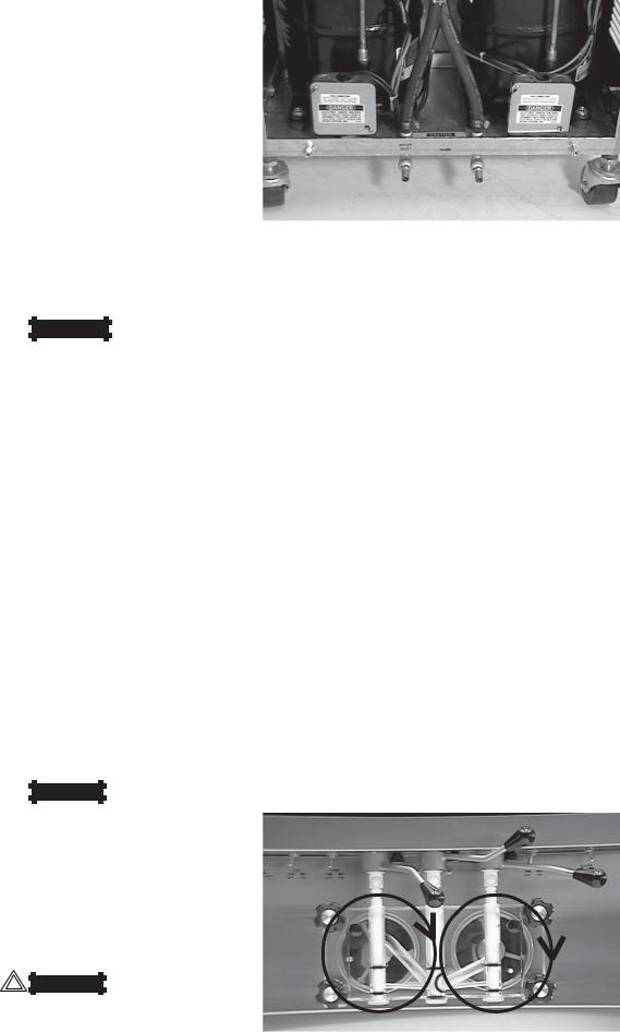
Figure 4. Water/Electrical Connections
F.Place the CLEAN-OFF-SERVE switches in the OFF position before continuing. Figure 11.
2.4 INSTALLING PERMANENT WIRING
Permanent wiring is required by local codes, the following procedure must be performed:
A.Refer to the nameplate at the rear of the freezer for specific electrical requirements. Make sure the power source in the building matches the freezer nameplate requirements. Bring the wires into the junction boxes through the access holes in the bottom rear of the freezer. Figure 4.
NOTE
Three phase freezers in areas of unbalanced electrical loads require special attention when connecting input electrical power. The unbalanced leg of power (called wild or high) must be connected to L2 in the junction box.
B.Remove the lower back panel and the two junction box covers located at the bottom of the freezer.
C.lnstall permanent wiring according to local code.
D.Check the auger shaft rotation by placing the MAIN DRIVE switch in the CLEAN position. Auger shaft rotation is clockwise as viewed through the clear plastic front door. If the rotation is not clockwise, turn main electrical power OFF. Then reverse L1 and L3 electrical power lines to the junction box (three phase only). Re-check auger shaft rotation. Figure 5.
Figure 5. Auger Rotation
2.5 MIX PUMP
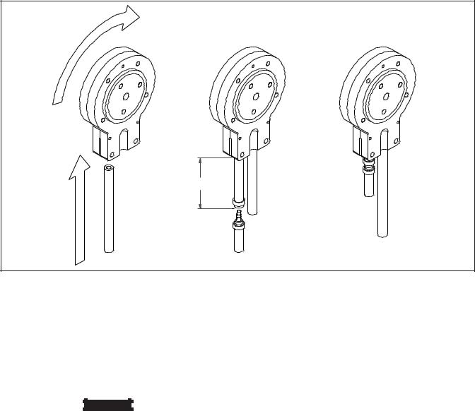
A.Mix Pump Hose Installation
Follow the steps below to install the mix pump hose.
1.Turn pump on.
2.Feed one end of mix pump hose into the entering or pick-up hose side (left) of black cover.
3.Gently push the hose into the black cover until it begins to feed.
6" (15cm)
Figure 6. Mix Hose Installation
4.Allow the hose to feed itself thru the pump until 6" (15cm) remains on the entering side.
5.Turn pump off.
6.Connect mix pump hose to pickup hose adapter using small hose clamp.
 CAUTION
DO NOT TWIST MIX PUMP HOSE.
7.Turn pump on.
8.Allow remaining 6" (15cm) of tubing to feed thru pump until hose adapter prevents further feeding.
9.Turn pump off.
10.Connect free end of mix pump hose to 3-way Tee as shown in Figure 7. When all connections are complete the 3- way Tee must be lower than the black pump housing. Figure 8.
5
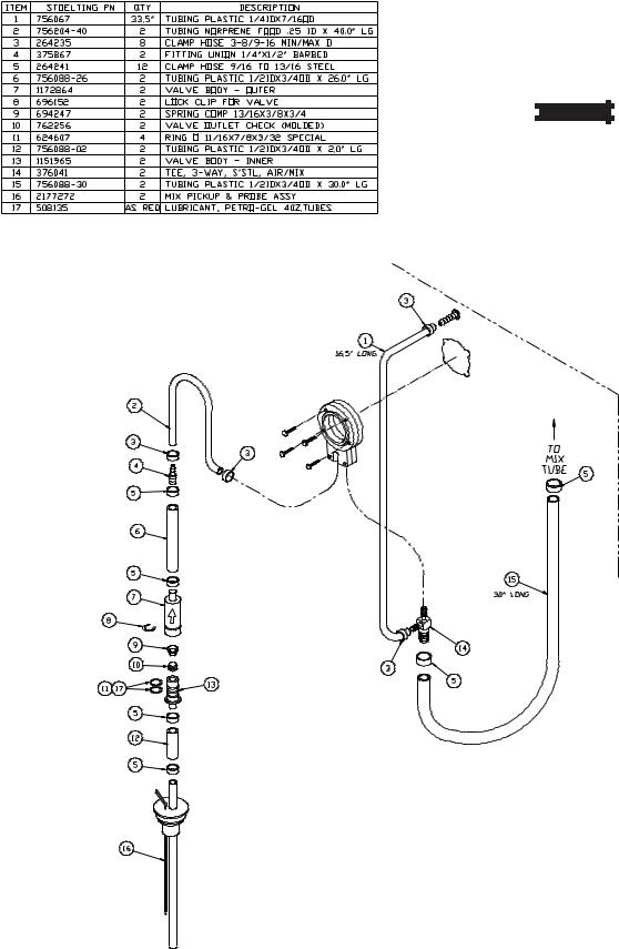
B.Connect 1/2 inch (12,7mm) I.D. plastic food grade tubing to mix check valve (Item 7) and then to the mix container. Observe check valve flow arrow.
Secure with hose clamps. Then place assembly thru hole in cover and install retainer clip. See Figure 9.
C.Connect 1/2 inch (12,7mm) I.D. plastic food grade tubing between the large port of air/mix tee and refrigerated mix transfer line. Secure with large hose clamp or equivalent. See Figure 9.

 CAUTION
AIR/MIX TEE MUST REMAIN BELOW THE
BLACK COVER/CLAMP. IF THE TEE IS
ABOVE THE PUMP MIX WILL DRAIN TO THE
AIR COMPRESSOR RESULTING IN PUMP
DAMAGE.
D.Connect mix low cords. Figure 9.
Figure 7. Mix Pump
6

ÅRefrigerated Mix Transfer Line
Large PortÆ |
Å 3-way Tee |
(Air/Mix) |
|
Figure 8. 3-way Tee
Low Mix Cord
Ì
Cover
È
Mix ÉRetainer
Container Clip
Figure 9. Mix Inlet Tube & Probe Assy. Clip
Ç
Hose Holder
Figure 10. Hose Holder
7
8
 Loading...