


Models 100F & C, 2217G
SERVICE MANUAL
Manual No. 513554
SERVICE MANUAL
MODELS 100 F & C AND 2217G SLUSH FREEZERS
This manual provides basic information about the freezer. Instructions and suggestions are given covering its operation and care.
The illustrations and specifications are not binding in detail. We reserve the right to make changes to the freezer without notice, and without incurring any obligation to modify or provide new parts for freezers built prior to date of change.
DO NOT ATTEMPT to service or operate the freezer until instructions and safety precautions in this manual are read completely and are thoroughly understood. If problems develop or questions arise in connection with installation, operation or servicing of the freezer, contact your distributor.
STOELTING, LLC |
Tele: 920-894-2293 |
502 HWY. 67 |
|
KIEL, WI 53042-1600 |
Fax: 920-894-7029 |

|
TABLE OF CONTENTS |
|
SECTION |
DESCRIPTION |
PAGE |
SECTION1 |
INTRODUCTION .............................................................................................................. |
1 |
1.1 |
Descriptions .................................................................................................................... |
1 |
1.2 |
Specifications .................................................................................................................. |
1 |
SECTION2 |
INSTALLATIONINSTRUCTIONS...................................................................................... |
3 |
2.1 |
Safety Precautions .......................................................................................................... |
3 |
2.2 |
Shipment and Transit ...................................................................................................... |
3 |
2.3 |
Freezer Installation .......................................................................................................... |
3 |
2.4 |
Adjusting Cup Dispensers ............................................................................................... |
7 |
SECTION3 |
INITIALSET-UPANDOPERATION ................................................................................. |
9 |
3.1 |
Operator's Safety Precautions ......................................................................................... |
9 |
3.2 |
Operating Controls and Indicators .................................................................................... |
9 |
3.3 |
Draining the Freezer For Disassembling and Cleaning ..................................................... |
10 |
3.4 |
Disassembly and Cleaning of Freezer Parts .................................................................... |
10 |
3.5 |
Sanitizing The Freezers and Freezer Parts ...................................................................... |
15 |
3.6 |
Assembly of Freezer ....................................................................................................... |
15 |
3.7 |
Mix Information ................................................................................................................ |
17 |
3.8 |
Freeze Down and Operation ............................................................................................ |
17 |
3.9 |
Dispensing Product ......................................................................................................... |
17 |
3.10 |
RoutineCleaning ............................................................................................................. |
17 |
3.11 |
PreventativeMaintenance ................................................................................................ |
17 |
3.12 |
Extended Storage ............................................................................................................ |
18 |
SECTION4 |
DECALS AND TAGS ....................................................................................................... |
21 |
4.1 |
How to Order Decals and Tags ........................................................................................ |
21 |
SECTION5 |
REFRIGERATIONCOMPONENTSANDADJUSTMENTS ............................................... |
23 |
5.1 |
Refrigeration System ....................................................................................................... |
23 |
5.2 |
Compressor ..................................................................................................................... |
23 |
5.3 |
Condenser ....................................................................................................................... |
23 |
SECTION6 |
ELECTRICALSYSTEMOPERATIONANDADJUSTMENTS ........................................... |
27 |
6.1 |
24 Hour Timer .................................................................................................................. |
27 |
6.2 |
Electronic Torque Control ................................................................................................ |
27 |
SECTION7 |
MAJORCOMPONENTREMOVALANDINSTALLATION ................................................. |
29 |
7.1 |
Introduction ..................................................................................................................... |
29 |
7.2 |
CondenserFanRemoval .................................................................................................. |
29 |
7.3 DriveMotorRemoval ........................................................................................................................... |
29 |
|
7.4 |
CompressorRemoval ...................................................................................................... |
29 |
7.5 |
Compressor Installation ................................................................................................... |
30 |
7.6 |
Drive Motor Installation .................................................................................................... |
31 |
7.7 |
Condenser Fan Installation .............................................................................................. |
31 |
SECTION8 |
TROUBLESHOOTING ..................................................................................................... |
33 |
8.1 |
Compressor Run Capacitor Open, Shorted or Blown ........................................................ |
34 |
8.2 |
Compressor Relay Defective or Burned Out ..................................................................... |
34 |
8.3 |
Compressor Starts and Runs, But Short Cycles On Overload Protector .......................... |
34 |
8.4 |
Compressor Runs Continuously ...................................................................................... |
34 |
8.5 |
Unit Noisy ....................................................................................................................... |
34 |
8.6 |
Compressor Will Not Start ............................................................................................... |
34 |
8.7 |
Compressor Will Not Start - Hums But Trips On Overload Protector ................................ |
35 |
8.8 |
Compressor Starts, But Does Not Switch Off of Start Winding ........................................ |
35 |

|
TABLE OF CONTENTS |
|
8.9 |
Compressor Start Capacitor Open, Shorted or Blown ...................................................... |
35 |
8.10 |
Freezer Will Not Start ...................................................................................................... |
35 |
8.11 |
Drive Motor Overload Trips (Freezer Shuts Down When Running) .................................... |
35 |
8.12 |
Compressor Will Not Run, But Drive Motor Runs ............................................................. |
35 |
8.13 |
Product Dispenses Incorrectly ......................................................................................... |
35 |
8.14 |
Product is Too Thin ......................................................................................................... |
36 |
8.15 |
Agitator Does Not Rotate................................................................................................. |
36 |
8.16 |
No Ice Crystals On Initial Freeze Down ........................................................................... |
36 |
8.17 |
Excessive Ice Crystals Above Divider Plate ..................................................................... |
36 |
8.18 |
Spigot Leaking or Stuck .................................................................................................. |
36 |
SECTION9 |
REPLACEMENT PARTS AND REFERENCE DRAWINGS .............................................. |
37 |
9.1 |
How to Order Parts .......................................................................................................... |
37 |
9.2 |
Spigot Assembly Parts.................................................................................................... |
37 |
9.3 |
Model 100C Parts List ..................................................................................................... |
39 |
9.4 |
Model 100F Parts List ..................................................................................................... |
41 |
9.5 |
Model 2217G Parts List ................................................................................................... |
43 |

|
LIST OF ILLUSTRATIONS |
|
Figure |
Title |
Page |
1 |
Model 100C - Front......................................................................................................................... |
2 |
2 |
Model 100C - Side .......................................................................................................................... |
2 |
3 |
Model 100F/2217G - Front.............................................................................................................. |
2 |
4 |
Model 100F/2217G - Side ............................................................................................................... |
2 |
5 |
Adjustable Leg ............................................................................................................................... |
3 |
6 |
Warning Label Locations - 100C ..................................................................................................... |
4 |
7 |
Warning Label Locations - 100F/2217G .......................................................................................... |
5 |
8 |
Space & Ventilation Requirements ................................................................................................. |
6 |
9 |
Electrical Plug ................................................................................................................................ |
6 |
10 |
Installing Sani-tray and Cover ......................................................................................................... |
6 |
11 |
Adjusting Cup Dispensers .............................................................................................................. |
7 |
12 |
OperatingControls ......................................................................................................................... |
9 |
13 |
RemoveSani-trayandCover ........................................................................................................... |
11 |
14 |
Draining Product............................................................................................................................. |
11 |
15 |
Removing Spigot Assembly ............................................................................................................ |
12 |
16 |
Removing Spigot O-Ring from Spigot Body ..................................................................................... |
12 |
17 |
Cut-away View of Spigot Assembly ................................................................................................ |
12 |
18 |
RemovingDriveCapandO-Ring ..................................................................................................... |
13 |
19 |
RemovingSealerRing .................................................................................................................... |
13 |
20 |
Removing Agitator Assembly and Lower Bushing ........................................................................... |
13 |
21 |
Removing Divider Plate from Agitator Fingers ................................................................................. |
14 |
22 |
RemovingDriveShaft ...................................................................................................................... |
14 |
23 |
Exploded View of Divider plate and Agitator Assembly ................................................................... |
14 |
24 |
Lubricating Drive Shaft .................................................................................................................... |
15 |
25 |
Installing Divider Plate and Agitator Assembly ................................................................................ |
16 |
26 |
Proper Installation of Sealer Ring .................................................................................................... |
16 |
27 |
Correct and Incorrect Alignment of Vertical Center Post Guide Hole ............................................... |
16 |
28 |
External Parts To Be Cleaned ........................................................................................................ |
19 |

LIST OF ILLUSTRATIONS
30 |
RemovingCompressorTerminalCover ............................................................................................ |
23 |
31 |
Check Winding ............................................................................................................................... |
23 |
32 |
Check Winding To Ground.............................................................................................................. |
23 |
33 |
CheckCondenser ........................................................................................................................... |
24 |
34 |
RemoveCap ................................................................................................................................... |
24 |
35 |
Install Gauge .................................................................................................................................. |
25 |
36 |
Adjust A.X.V. ................................................................................................................................. |
25 |
37 |
Filter Drier Replacement ................................................................................................................. |
26 |
38 |
TorqueControl ................................................................................................................................ |
27 |
39 |
TensionSpring ............................................................................................................................... |
27 |
40 |
RemovingTorqueControl ................................................................................................................ |
28 |
41 |
FanRemoval .................................................................................................................................. |
29 |
42 |
Disconnect Wire............................................................................................................................. |
29 |
43 |
DriveMotorRemoval ....................................................................................................................... |
29 |
44 |
CompressorRemoval ..................................................................................................................... |
30 |
45 |
Install Compressor ......................................................................................................................... |
30 |
46 |
Remove Filter Drier ......................................................................................................................... |
31 |
47 |
TensionSpring ............................................................................................................................... |
31 |
48 |
Fan Installation ............................................................................................................................... |
31 |
49 |
Exploded View of Spigot Assembly ................................................................................................ |
37 |
50 |
Model 100C Exploded View ............................................................................................................ |
38 |
51 |
Model 100F Exploded View ............................................................................................................ |
40 |
52 |
Model 2217G Exploded View .......................................................................................................... |
42 |

SECTION 1
INTRODUCTION
1.1 DESCRIPTION
Models 100C, 100F, and 2217G freezers are gravity fed. The freezers are equipped with fully automatic controls to provide a uniform product. The freezers are designed to operate with most neutral bases and concentrated flavors.
1.2 SPECIFICATIONS
This manual is designed to assist qualified service personnel and operators in the installation, operation and maintenance of the Models 100C, 100F, and 2217G freezers.
|
100C COUNTER |
|
100F FLOOR |
|
2217G FLOOR |
|
|
MODEL FREEZER |
|
MODEL FREEZER |
|
MODEL FREEZER |
|
|
|
|
|
|
|
|
DIMENSIONS |
width: 15" (38.1 cm) |
|
width: 15" (38.1 cm) |
|
width: 15" (38.1 cm) |
|
|
depth: 29.5" (74.8 cm) |
|
depth: 19.25" (48.9 cm) |
|
depth: 19.25" (48.9 cm) |
|
|
height: 34.75" (88.3 cm) |
|
height: 61.38" (156 cm) |
|
height: 61.38" (156 cm) |
|
|
|
|
|
|
|
|
WEIGHT |
130 lbs. (58.9 kg) |
|
140 lbs. (63.5 kg) |
|
140 lbs. (63.5 kg) |
|
|
|
|
|
|
|
|
ELECTRICAL |
1 Phase, 115 VAC* |
|
1 Phase, 115 VAC* |
|
1 Phase, 115 VAC* |
|
|
1/12 HP Drive Motor |
|
1/12 HP Drive Motor |
|
1/12 HP Drive Motor |
|
|
|
|
|
|
|
|
COMPRESSOR |
2500 BTUH** |
|
2500 BTUH** |
|
5200 BTUH** |
|
|
(frozen product output) |
|
(frozen product output) |
|
(frozen product output) |
|
|
- Approx. 11 total running |
|
- Approx. 11 total running |
|
- Approx. 9 total running |
|
|
amps. |
- |
amps. |
- |
amps. |
- |
|
Use 15 Amp circuit breaker |
|
Use 15 Amp circuit breaker |
|
Use 15 Amp cirucit breaker |
|
|
|
|
|
|||
COOLING |
Air cooled requires minimum |
Requires unobstructed front |
Requires unobstructed front |
|||
|
3" (7.6 cm) air clearance on |
and 6" minimum (15.2 cm) |
|
and 6" minimum (15.2 cm) |
|
|
|
sides and 1" (2.5 cm) at rear |
clearance at back of unit. No |
clearance at back of unit. No |
|||
|
of unit. |
|
clearance needed on side of |
clearance needed on side of |
||
|
|
|
unit. |
|
unit. |
|
|
|
|
|
|
|
|
HOPPER |
10 gallons (37.9 liters) |
|
10 gallons (37.9 liters) |
|
10 gallons (37.9 liters) |
|
|
|
|
|
|
|
|
* A transformer is required if voltage is over 126.5 volts or under 103 volts. ** Under normal operating conditions.
1

|
|
|
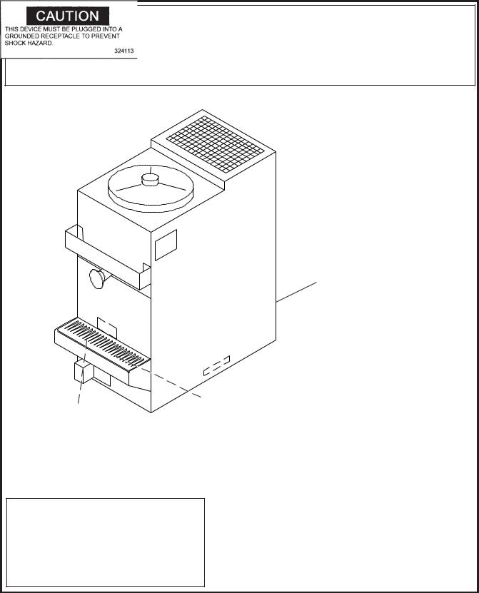
Figure 1 |
|
Figure 2 |
Model 100C - Front |
|
Model 100C - Side |
Figure 3
Model 100F/2217G - Front
Figure 4 |
Model 100F/2217G - Side |
NOTE: Figures in parenthesis are in centimeters.
2
SECTION 2
INSTALLATION INSTRUCTIONS
2.1SAFETYPRECAUTIONS
Do not attempt to operate the freezer until the safety precautions and operating instructions in this manual are read and completely understood.
Take notice of all warning labels on the freezer (Figures 6 & 7). The labels have been put there to help maintain a safe working environment. The labels have been designed to withstand washing and cleaning. All labels must remain legible for the life of the freezer. Labels should be checked periodically to be sure they can be recognized as warning labels.
If danger, warning, or caution labels are needed, indicate the part number, type of label, location of label, and quantity required along with your address and advise your distributor.
2.2 SHIPMENT AND TRANSIT
The freezer has been assembled, operated and inspected at the factory. Upon arrival at the final destination, the complete freezer must be checked for any damage which may have occurred during transit.
With the method of packaging used, the freezer should arrive in excellent condition. THE CARRIER IS
RESPONSIBLE FOR ALL DAMAGE IN TRANSIT, WHETHER VISIBLEOR CONCEALED.
Do not pay the freight bill until the freezer has been checked for damage. Have the carrier note any visible damage on the freight bill. If concealed damage and/or shortage is found later, advise the carrier within 10 days and request inspection. The customer must place claim for damages and/or shortages in shipment with the carrier.
2.3FREEZERINSTALLATION
Installation of the freezer involves moving the freezer close to its permanent location, removing all crating, setting in place, assembling parts, and cleaning.
A.Uncrate the freezer.
B.The floor model freezers must be placed in a
solid level position. To level the freezer, turn the bottom part of each leg in or out. Place a level on top of the hopper, with the cover removed, to check whether or not the freezer is level (Fig. 5).
NOTE
Accurate leveling is necessary for correct drainage of freezer barrel and to insure proper operation.
C.The counter model freezer must be placed on a solid level surface. Place the rubber pad furnished under the freezer to create a seal to that surface. The counter model freezer is air-cooled and discharges at the top. AL LOUVERED PANELS MUST have 3" of clearance on sides of unit, 10" of clearance at the top, and 1" clearance at rear of unit for proper cooling.
Figure 5
Adjustable Leg
3
IMPORTANTNOTICETOOPERATOR
BEFORE INSTALLING EQUIPMENT, READ THE OWNER'S MANUAL CAREFULLY. TAKE NOTE OF ALL INSTRUCTIONS AND CAUTION
DECALSONTHISEQUIPMENT.
GOOVERTHEMANUALTHOROUGHLYANDPOINTOUTALLDECALSTOYOUREMPLOYEES,SOTHEYUNDERSTANDHOWTOSAFELY
OPERATETHISEQUIPMENT.
DO NOT REMOVE, DEFACE, OR PAINT OVER ANY DECALS. THEY ARE THERE FOR YOUR SAFETY.
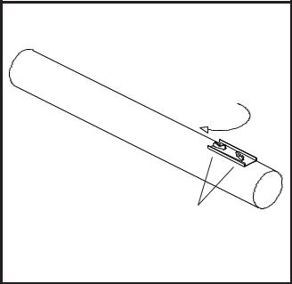
(Behind Sani-tray)
(Behind Sani-tray)
CAUTION
THIS DEVICE MUST BE PLUGGED INTO A PROPERLY GROUNDED
RECEPTACLE TO PREVENT ELECTRICAL SHOCK HAZARD.
TAMPERING WITH THE PLUG OR USING VOLTAGES OTHER THAN
THE SPECIFICATIONS ON I.D. PLATE WILL VOID YOUR WARRANTY.
REFER TO OWNER'S MANUAL FOR INSTALLATION
INSTRUCTIONS.
723529
Figure 6
Warning Label Locations - 100C
4
IMPORTANTNOTICETOOPERATOR
BEFORE INSTALLING EQUIPMENT, READ THE OWNER'S MANUAL CAREFULLY. TAKE NOTE OF ALL INSTRUCTIONS AND CAUTION
DECALSONTHISEQUIPMENT.
GOOVERTHEMANUALTHOROUGHLYANDPOINTOUTALLDECALSTOYOUREMPLOYEES,SOTHEYUNDERSTANDHOWTOSAFELY OPERATETHISEQUIPMENT.
DO NOT REMOVE, DEFACE, OR PAINT OVER ANY DECALS. THEY ARE THERE FOR YOUR SAFETY.
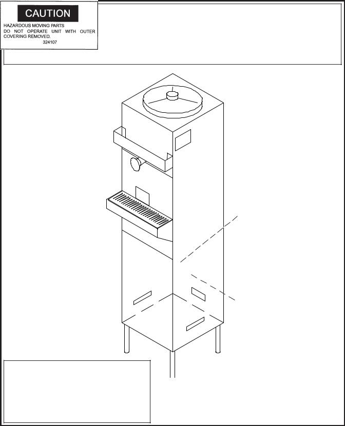
(Affixed to condenser shroud)
|
(Affixed to condenser shroud) |
|
|
|
|
CAUTION
THIS DEVICE MUST BE PLUGGED INTO A PROPERLY GROUNDED
RECEPTACLE TO PREVENT ELECTRICAL SHOCK HAZARD.
TAMPERING WITH THE PLUG OR USING VOLTAGES OTHER THAN THE
SPECIFICATIONS ON I.D. PLATE WILL VOID YOUR WARRANTY.
REFER TO OWNER'S MANUAL FOR INSTALLATION
INSTRUCTIONS.
7 2 3 5 2 9
Figure 7
Warning Label Locations - 100F/2217G
5
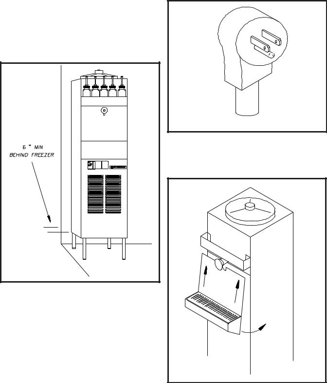
D.The floor model freezers are equipped with air-cooled condensers and require correct ventilation. The front of the freezer is the air intake and must be unobstructed. Air discharges out of the rear of the unit. Do not obstruct the discharge. Allow a 6" (15.2 cm) clearance behind the unit (Fig. 8).
CAUTION
FAILURETOPROVIDEADEQUATEVENTILATIONWILL VOIDWARRANTY!
Figure 8
Space and Ventilation Requirements
E.Place the ON-OFF-STIR ONLY toggle switch in the OFF position. This switch is located on the lower left of the freezer, under the drip tray and cover.
F.Connect the power cord. The plug is designed for 115 volt/15 amp duty. The unit must be connected to a properly grounded receptacle. The electrical cord furnished as part of the freezer has a three prong grounding type plug (Fig.9). The use of an extension cord is not recommended. If one must be used, use one with a wire, size 12 gauge or heavier, with a ground. Do not use an adaptor to avoid grounding equipment.
CAUTION
DO NOT ALTER OR DEFORM PLUG IN ANY WAY!
Figure 9
Electrical Plug
G.Install the sani-tray, cover and miscellaneous parts on the freezer (Fig. 10).
Figure 10
Installing Sani-tray and Cover
6
2.4 ADJUSTING CUP DISPENSERS
To adjust the cup dispensers, install the size cup desired into the dispenser and turn the wing nuts on the dispenser mounting bracket until enough tension is applied to the rim ofthecuptokeepitfromdroppingout(Fig.11). Donotovertighten the wing nuts.
WING NUTS |
Figure 11
AdjustingCupDispensers
7
8
 Loading...