


Model E131-OT2 / F131-OT2
SERVICE MANUAL
Manual No. 513648 |
Rev.0 |

This manual provides basic information about the machine. Instructions and suggestions are given covering its operation and care.
The illustrations and specifications are not binding in detail. We reserve the right to make changes to the machine without notice, and without incurring any obligation to modify or provide new parts for machines built prior to date of change.
DO NOT ATTEMPT to operate the machine until instructions and safety precautions in this manual are read completely and are thoroughly understood. If problems develop or questions arise in connection with installation, operation, or servicing of the machine, contact Stoelting.
|
Stoelting Foodservice Equipment |
Customer Service: 888.429.5920 |
|
502 Highway 67 |
Fax: 800.545.0662 |
|
||
|
Kiel, WI 53042-1600 |
Email: foodservice@stoelting.com |
|
||
|
U.S.A. |
|
stoeltingfoodservice.com
Main Tel: 800.558.5807 |
© 2014 PW Stoelting, LLC |
Fax: 920.894.7029 |
|
|
|

A Few Words About Safety
Safety Information
Read and understand the entire manual before operating or maintaining Stoelting equipment.
This manual provides the operator with information for the safe operation and maintenance of Stoelting equipment. As with any machine, there are hazards associated with their operation. For this reason safety is emphasized throughout the manual. To highlight specific safety information, the following safety definitions are provided to assist the reader.
The purpose of safety symbols is to attract your attention to possible dangers. The safety symbols, and their explanations, deserve your careful attention and understanding. The safety warnings do not by themselves eliminate any danger. The instructions or warnings they give are not substitutes for proper accident prevention measures.
If you need to replace a part, use genuine Stoelting parts with the correct part number or an equivalent part. We strongly recommend that you do not use replacement parts of inferior quality.
Safety Alert Symbol:
This symbol Indicates danger, warning or caution. Attention is required in order to avoid serious personal injury. The message that follows the symbol contains important information about safety.
Signal Word:
Signal words are distinctive words used throughout this manual that alert the reader to the existence and relative degree of a hazard.
 WARNING
The signal word “WARNING” indicates a potentially hazardous situation, which, if not avoided, may result in death or serious injury and equipment/property damage.
 CAUTION
The signal word “CAUTION” indicates a potentially hazardous situation, which, if not avoided, may result in minor or moderate injury and equipment/property damage.
CAUTION
The signal word “CAUTION” not preceded by the safety alert symbol indicates a potentially hazardous situation, which, if not avoided, may result in equipment/property damage.
NOTE (or NOTICE)
The signal word “NOTICE” indicates information or procedures that relate directly or indirectly to the safety of personnel or equipment/property.

|
TABLE OF |
|
|
CONTENTS |
|
Section |
Description |
Page |
1 |
Description and Specifications |
|
1.1 |
Description ................................................................................................. |
1 |
1.2 |
Specifications ............................................................................................. |
1 |
1.3 |
Modes of Normal Operation ........................................................................ |
4 |
1.4 |
Mix Level Indicators .................................................................................... |
6 |
1.5 |
HopperRefrigeration ................................................................................... |
6 |
1.7 |
Motor Profile Cutout Compensation ............................................................ |
6 |
2 |
Installation Instructions |
|
2.1 |
Safety Precautions ..................................................................................... |
9 |
2.2 |
Shipment and Transit ................................................................................. |
9 |
2.3 |
Machine Installation .................................................................................... |
9 |
3 |
Initial Set-Up and Operation |
|
3.1 |
Operator’s Safety Precautions .................................................................... |
11 |
3.2 |
Operating Controls and Indicators ............................................................... |
11 |
3.3 |
Important Information Regarding Cleaning and Sanitizing ............................ |
13 |
3.4 |
Disassembly of Machine Parts ................................................................... |
14 |
3.5 |
Cleaning Disassembled Parts ..................................................................... |
15 |
3.6 |
Sanitizing Machine Parts ............................................................................ |
15 |
3.7 |
Cleaning the Machine ................................................................................. |
15 |
3.8 |
Assembling the Machine ............................................................................ |
16 |
3.9 |
Sanitizing ................................................................................................... |
16 |
3.10 |
Initial Freeze Down and Operation .............................................................. |
17 |
3.11 |
Normal Freeze Down and Operation ........................................................... |
18 |
3.12 |
Mix Information ........................................................................................... |
18 |
4 |
Maintenance and Adjustments |
|
4.1 |
Machine Adjustment................................................................................... |
19 |
4.2 |
Product Consistency Adjustment ............................................................... |
19 |
4.3 |
Locking the Control Panel........................................................................... |
19 |
4.4 |
Obtaining Readings and Modifying Settings ................................................ |
19 |
4.5 |
Readings .................................................................................................... |
21 |
4.6 |
Adjustments ............................................................................................... |
22 |
4.7 |
Other Settings ............................................................................................ |
22 |
4.8 |
Drive Belt Tension Adjustment .................................................................... |
23 |
4.9 |
CondenserCleaning ................................................................................... |
23 |
4.10 |
PreventativeMaintenance ........................................................................... |
24 |
4.11 |
Extended Storage....................................................................................... |
24 |

Section |
Description |
Page |
5 |
Refrigeration System |
|
5.1 |
Refrigeration System .................................................................................. |
25 |
5.2 |
RefrigerantRecoveryandEvacuation .......................................................... |
25 |
5.3 |
RefrigerantCharging ................................................................................... |
26 |
5.4 |
Compressor ................................................................................................ |
27 |
5.5 |
Condenser .................................................................................................. |
28 |
5.6 |
Valves ........................................................................................................ |
28 |
A. |
Thermostatic Expansion Valve (TXV) .................................................................. |
28 |
B. |
Check Valve ......................................................................................................... |
29 |
C. |
High Pressure Cutout ......................................................................................... |
29 |
D. |
Hot Gas Bypass .................................................................................................. |
30 |
E. |
Evaporator Pressure Regulator (EPR) ............................................................... |
31 |
F. |
Water Valve (Water Cooled Models Only) ........................................................... |
31 |
5.7 |
Solenoid ..................................................................................................... |
32 |
5.8 |
Filter Drier .................................................................................................. |
34 |
5.9 |
CapillaryTube ............................................................................................ |
34 |
6 |
Electrical and Mechanical Control Systems |
|
6.1 |
IntelliTecController ..................................................................................... |
35 |
6.2 |
Contactors.................................................................................................. |
35 |
6.3 |
DriveMotor ................................................................................................. |
36 |
6.4 |
Capacitors .................................................................................................. |
37 |
6.5 |
Gearbox ..................................................................................................... |
38 |
6.6 |
Condenser Fan Motor (Air Cooled Models Only) ......................................... |
38 |
6.7 |
Spigot Switch ............................................................................................. |
39 |
6.8 |
TemperatureControlSensor ....................................................................... |
40 |
7 |
Troubleshooting |
|
7.1 |
Error Codes ................................................................................................ |
41 |
7.2 |
Troubleshooting .......................................................................................... |
41 |
7.3 |
ServicingTip ............................................................................................... |
43 |
7.4 |
Troubleshooting - Machine .......................................................................... |
44 |
8 |
Replacement Parts |
|
8.1 |
Decals & Lubrication .................................................................................. |
45 |
8.2 |
Auger Shaft and Faceplate Parts ................................................................ |
46 |
8.3 |
Machine Front ............................................................................................ |
48 |
8.4 |
Panels ........................................................................................................ |
48 |
8.5 |
Left Side ..................................................................................................... |
49 |
8.6 |
Right Side .................................................................................................. |
50 |
8.7 |
Front .......................................................................................................... |
50 |
8.8 |
Rear ........................................................................................................... |
52 |
8.9 |
Refrigeration Diagram & Wiring Diagram ..................................................... |
54 |

SECTION 1
INTRODUCTION
1.1 DESCRIPTION
The Stoelting E131OT2 and F131OT2 counter machines are gravity fed. The machines are equipped with fully automatic controls to provide a uniform product. They are designed to operate with almost any type of commercial soft serve or non-dairy mixes available, including: ice milk, ice cream, yogurt, and frozen dietary desserts.
This manual is designed to assist qualified service personnel and operators in the installation, operation and maintenance of the Stoelting E131OT2 and F131OT2 gravity machine.
Figure 1-1 E131OT2 / F131OT2 Machine
1.2 SPECIFICATIONS
Figure 1-2 Specification
1

1.2E131I SPECIFICATIONS
|
|
Model E131OT2 |
|
Dimensions |
Machine |
with crate |
|
width |
22'' (55,9 cm) |
28'' (71,1 cm) |
|
height |
34-3/4'' (88,3 cm) |
40-1/4'' (102,2 cm) |
|
depth |
28-1/2'' (72,4 cm) |
35-1/4'' (89,5 cm) |
|
Weight |
370 lbs (167,8 kg) |
450 lbs (204,1 kg) |
|
Electrical |
1 Phase, 208-230 VAC, 60Hz |
||
running amps |
|
approximately 12A |
|
connection type |
NEMA6-20P power cord provided |
||
International Option |
1 Phase, 220-240 VAC, 50Hz |
||
Compressor |
|
8,600 Btu/hr (R-404A) |
|
Drive Motor |
|
Two - 3/4 hp |
|
Air Flow |
Air cooled units require 3" (7,6 cm) air space on both sides |
||
Plumbing Fittings |
Water cooled units require 3/8" N.P.T. water and drain fittings. |
||
Hopper Volume |
Two - 3 gallon (11,35 liters) |
||
Freezing Cylinder |
Two - 0.5 gallon (2 quart), 1,89 liters |
||
Volume |
|||
|
|
||
Production |
5 GPH (18,93 liters) each Freezing Cylinder |
||
Capacity |
8.5 GPH (32,18 liters) both Freezing Cylinders |
||
|
E131OT2 |
|
Refrigerant |
R-404A |
|
Charge |
(W/C) 26 oz |
|
(A/C) 32 oz |
||
|
||
Suction Pressure |
One Cylinder 22-24 psig |
|
(at 72°F) |
Hopper Only 14 psig |
|
Discharge Pressure |
225-235 psig |
|
|
|
|
Hot Gas Bypass |
14 psig (only hopper running) |
|
Pressure |
||
|
||
EPR Valve |
59-61 psig |
Menu |
Display |
Value |
Basic |
CutOut |
* amps |
|
Cut In T |
22 °F |
|
Cycles |
20 count |
|
Stir On |
15 seconds |
|
Stir Off |
300 seconds |
Advanced |
On Time |
25 seconds |
|
Off Time |
450 seconds |
|
Stb Time |
120 minutes |
|
Sl1DrvOn |
120 seconds |
|
Sl1DrOff |
180 seconds |
|
Sl2CutIn |
35 °F |
|
Sl2CtOut |
30 °F |
|
DftOffTm |
600 seconds |
Storage |
Refriger |
** 2 Hopper |
(Left |
HprCutIn |
37.5 °F |
control |
HprCtOut |
32 °F |
only) |
HprOffst |
8 °F |
|
Hpr Off |
13 minutes |
|
Hpr On |
130 seconds |
*CutOut amps must be set on site.
**The Refriger setting on the right control board must be set to None.
2

1.2F131I SPECIFICATIONS
|
|
Model F131OT2 |
|
Dimensions |
Machine |
with crate |
|
width |
22'' (55,9 cm) |
28'' (71,1 cm) |
|
height |
34-3/4'' (88,3 cm) |
40-1/4'' (102,2 cm) |
|
depth |
28-1/2'' (72,4 cm) |
35-1/4'' (89,5 cm) |
|
Weight |
385 lbs (174,6 kg) |
470 lbs (213,1 kg) |
|
Electrical |
1 Phase, 208-230 VAC, 60Hz |
||
running amps |
|
approximately 12A |
|
connection type |
NEMA6-20P power cord provided |
||
International Option |
1 Phase, 220-240 VAC, 50Hz |
||
Compressor |
12,000 Btu/hr (R-404A) |
||
Drive Motor |
|
Two - 3/4 hp |
|
Air Flow |
Air cooled units require 3" (7,6 cm) air space on both sides |
||
Plumbing Fittings |
Water cooled units require 3/8" N.P.T. water and drain fittings. |
||
Hopper Volume |
Two - 3 gallon (11,35 liters) |
||
Freezing Cylinder |
Two - 0.85 gallon (3.4 quart), 3,22 liters |
||
Volume |
|||
|
|
||
Production |
8 GPH (30,29 liters) each Freezing Cylinder |
||
Capacity |
11.5 GPH (43,53 liters) both Freezing Cylinders |
||
|
F131OT2 |
|
Refrigerant |
R-404A |
|
Charge |
(W/C) 32 oz |
|
(A/C) 42 oz |
||
|
||
Suction Pressure |
One Cylinder 22-24 psig |
|
(at 72°F) |
Hopper Only 14 psig |
|
Discharge Pressure |
225-235 psig |
|
|
|
|
Hot Gas Bypass |
14 psig (only hopper running) |
|
Pressure |
||
|
||
EPR Valve |
59-61 psig |
Menu |
Display |
Value |
Basic |
CutOut |
* amps |
|
Cut In T |
22 °F |
|
Cycles |
20 count |
|
Stir On |
15 seconds |
|
Stir Off |
300 seconds |
Advanced |
On Time |
15 seconds |
|
Off Time |
450 seconds |
|
Stb Time |
120 minutes |
|
Sl1DrvOn |
120 seconds |
|
Sl1DrOff |
180 seconds |
|
Sl2CutIn |
33 °F |
|
Sl2CtOut |
30.5 °F |
|
DftOffTm |
600 seconds |
Storage |
Refriger |
** 2 Hopper |
(Left |
HprCutIn |
37.5 °F |
control |
HprCtOut |
32 °F |
only) |
HprOffst |
8 °F |
|
Hpr Off |
13 minutes |
|
Hpr On |
130 seconds |
*CutOut amps must be set on site.
**The Refriger setting on the right control board must be set to None.
3

1.3 MODES OF NORMAL OPERATION
Following are details of the operational modes of the IntelliTec control.
NOTE:
The preset amounts, times, and temperatures listed below are references to actual settings on the IntelliTec control. Refer to Table 1-1 on page 7 for details on each setting.
A. INITIAL STATUS
When the Main Freezer Power and Freezing Cylinder switches are placed in the ON position, the machine will start in the “Sleep 1 Mode". The display will read "Sleep 1 Mode". The control will eventually move into the “Sleep 2” mode if the PUSH TO FREEZE button is not pressed. When the PUSH TO FREEZE button is pressed the control will move to the “Serve Mode”.
B. SERVE MODE
When the PUSH TO FREEZE button is pressed or a spigot handle is pulled, the “Serve Mode” begins. The drive motor starts, and after a 3 second delay, the compressor starts. The display reads “FREEZING” on the top line and a bar on the bottom line increases with product consistency. A toroid on the IntelliTec control senses increasing drive motor amperage as the product comes to consistency in the freezing cylinder. When the control senses the product is at 75% of consistency, the display will read "SERVE", the amber LED will go out, and the green LED will flash. At this time, product can be served from the machine. The drive motor and compressor will continue to run until the toroid reads a preset value (CutOut amps). When the toroid reads the CutOut amps on the drive motor, the compressor turns off and the green LED will remain lit. After a 3 second delay, the drive motor turns off. The product in the freezing cylinder is now at serving temperature and consistency.
After product is at consistency, the IntelliTec control continuously monitors refrigerant temperature through a thermistor mounted on the side of the freezing cylinder. When the temperature increases to a preset amount (Cut In T), a 3-second drive motor pre-stir analyzes product consistency. The pre-stir check is also performed each time the spigot handle is opened. This check prevents overfreezing of product, especially during frequent, small volume draws. If the product requires a freezing cycle, the control will start the cycle.
During the “Serve Mode”, a stir cycle starts. This cycle is independent of the freezing cycle and is based on preset times (Stir On and Stir Off). The stir cycle prevents product separation. If a freezing cycle is initiated, the timer is reset.
In addition to the "Serve Mode" freezing cycle, there is a freezing cycle based on a preset time (DftOffTime). If this time is attained without a freezing cycle, the control will automatically start a freezing cycle.
The machine will remain in “Serve Mode” until the cycle count setting is attained. The cycle count is the number of active freezing cycles and is based on a preset value
Figure 1-3 Serve Mode
(Cycles). Once the cycle count has been reached without user interruption, the control will move into the "Standby Mode".
If the PUSH TO FREEZE button is pressed or a spigot handle is pulled, the cycle count is reset and the control will move to the beginning of the "Serve Mode". Refer to Figure 1-3 for a graphical representation of the "Serve Mode".
C.STANDBYMODE
If no product has been drawn from the spigot and the preset number of active freezing cycles is met, the control moves into the “Standby Mode”. In "Standby Mode", the freezing cycleisbasedonpresettimers(OnTimeandOffTime),and prevents ice crystals from building up in the product. Because the product remains partially frozen, it can quickly returntoservableconsistencywhenthePUSHTOFREEZE button is pressed.
During “Standby Mode”, the stir cycle runs. This cycle is based on preset, timed intervals (Stir On and Stir Off) and prevents product separation.
The "Standby Mode" maintains product quality during slow times, while minimizing reactivation time. This mode lasts for a preset time (Stb Time). Once this time has been reached without user interruption, the control moves into
Figure 1-4 Standby Mode
4
the "Sleep 1 Mode". Refer to Figure 1-4 for a graphical representation of the "Standby Mode".
If a spigot is opened or the PUSH TO FREEZE button is pressed, the control will move to “Serve Mode”. Product in the front of the freezing cylinders may or may not be at consistency. The state of the product is dependant on a number of variables but will come to consistency quickly.
D. SLEEP 1 MODE
After the “Standby Mode” time has expired without user interruption, the control will move into the “Sleep 1 Mode”. During the "Sleep 1 Mode", the stir cycle is handled by preset timers (Sl1DrvOn and Sl1DrOff), and allows product to melt to a liquid state by using agitation cycles without any flow of refrigerant. Although the product temperature never increases above 40°F, the product thaws rapidly which minimizes product breakdown. The control will stay in the “Sleep 1 Mode” until sensing a preset temperature (Sl2CutIn). When this temperature has been reached without user interruption, the control will move to the "Sleep 2 Mode". Refer to Figure 1-5 for a graphical representation of the "Sleep 1 Mode".
Figure 1-5 Sleep 1 Mode
If a spigot is opened or the PUSH TO FREEZE button is pressed, the control will move to “Serve Mode”. If the spigot is opened in "Sleep 1 Mode", the product will not be at consistency. The operator must wait until the first "Serve Mode" freezing cycle has completed to serve product.
E. SLEEP 2 MODE
The “Sleep 2 Mode” maintains the freezing cylinder temperaturebetweentwopresetvalues(Sl2CutInandSl2CtOut). During the “Sleep 2 Mode”, the stir cycle runs. This cycle is based on preset, timed intervals (Stir On and Stir Off) and prevents product separation. The "Sleep 2 Mode" is often referred to by customers as the “night mode” and the machine will stay in this mode until a spigot is opened or the PUSH TO FREEZE button is pressed. When this occurs, the control will move to “Serve Mode”. If the spigot is opened at this time, the product will be liquid. The operator must wait until the first "Serve Mode" freezing cycle has completed to serve product. Refer to Figure 1-6 for a graphical representation of the "Sleep 2 Mode".
Figure 1-6 Sleep 2 Mode
F. INTELLITEC RESTART (VERSION 3.5 OR HIGHER)
If a hard error occurs (refer the hard error list below), the IntelliTec control will wait 5 minutes then attempt to clear the error by restarting itself. The control will count each restart attempt. The restart count will reset if the PUSH TO FREEZE button is pressed, the spigot is pulled, or the Freezing Cylinder OFF/ON switch is placed in the OFF position.
The following are considered hard errors: ERRORCODE MALFUNCTION
2HighTorque
3Run Time
4Clean
7 |
DriveMotor |
9 |
High Pressure Cutout |
When a restart occurs, the second line of the display will read "Restart" and the backlight will blink. This will occur regardless of the system mode.
G. SLEEP 3 MODE (VERSION 3.5 OR HIGHER)
If a high torque, run time, or drive motor error condition occurs on the third restart attempt, the control will move to the "Sleep 3 Mode".
In "Sleep 3 Mode" freezing cylinder refrigeration will run for 4 seconds every 10 minutes. This ensures the product temperature never increases above 40°F. The stir cycle and the auger do not run during "Sleep 3 Mode".
The control will exit "Sleep 3 Mode" if the PUSH TO FREEZE button is pressed, the spigot is pulled, or the Freezing Cylinder OFF/ON switch is placed in the OFF position.
H.CLEANMODE
When the CLEAN button is pressed on the left side, all hopper refrigeration stops. When the CLEAN button is pressed on the right side, only the right barrel freezing cycle stops. In either case, the drive motor of that barrel starts and will run for 20 minutes and a 5 minute countdown timer is displayed. After the time has elapsed, an optional audible alarm will sound if this accessory has been installed. The
5

audible alarm is a reminder for the operator to end the "Clean Mode" when cleaning is completed.
If the machine is kept in "Clean Mode" for more than 20 minutes, the auger drive motor stops, the hopper refrigeration starts, and an error code (E4) is displayed on the display panel. The error code prevents damage to the machine that could occur during an extended clean mode (Refer to Section 8 - Troubleshooting for details). To clear this error, place the Freezing Cylinder Off-On switch in the Off position and back in the On position. If the machine is still being cleaned, pushing the CLEAN button will reset the timer and restart the "Clean Mode".
1.4 MIX LEVEL INDICATORS
The hoppers are equipped with a sensor that monitors mix level. When the mix level drops below the sensor probe, the lower line of the display will read "Low Mix" and the display will flash. To clear the "Low Mix" error, add mix to the hopper.
1.5 HOPPER REFRIGERATION
TheIntelliTeccontrolisprogrammedtohandlerefrigeration of the hopper independently from the freezing cylinder. The left control maintains hopper temperature between two preset values (HprCutIn and HprCtOut).
NOTE
The Refriger setting should be 2 Hopper for the Left control and None for the right control.
The hopper refrigeration cycle starts when the temperature ofeitherhopperreachestheHprCutInvalueandstopswhen both hoppers reach the HprCutOut value.
In addition to this refrigeration cycle, hopper refrigeration may start when the freezing cycle starts. This reduces compressor cycles which preserves compressor life. Hopper refrigeration will start if the hopper temperature is above a preset value (HprOffst + HprCtOut). This value is always between HprCutIn and HprCtOut. Refrigeration of the hopper will continue until the HprCtOut is reached or until the freezing cycle is completed in the freezing cylinder.
The refrigeration cycle will run for a maximum of 4 minutes. After 4 minutes, the refrigeration cycle will stop for a minimum of 3 minutes. At the expiration of 3 minutes, the control will check product temperature. If product temperature is at or above HprCutIn, another refrigeration cycle will start.
NOTE
If the temperature in the cabinet stays above 50°F for more than two hours, the machine will go into Sleep Mode and a clean message will be shown on the display.
1.6 OPERATION DURING SENSOR FAILURE
The IntelliTec control is designed to allow the machine to continue to function if a temperature sensor failure occurs. If a sensor fails, the display will show the error and the
control will run the machine on timers for the freezing cycle or hopper refrigeration. This allows the operator to continue toserveproductfromthemachineuntilproperservicingcan be completed.
A. SERVE AND STANDBY MODE
In the event of a temperature sensor failure on a freezing cylinder, the IntelliTec control will function in two modes, "Serve Mode" and "Standby Mode". When the product is at consistency in "Serve Mode", the IntelliTec control uses a timer instead of the sensor and will not start another freezing cycle until a preset value (DftOffTme) is met.
The control will monitor product after it is at consistency, activating the stir cycle and counting the number of cycles. When the cycle count is reached, the control will move to "Standby Mode".
Figure 1-7 Serve Mode (Sensor Failure)
The "Standby Mode" is the same as in normal operation with the exception of when the preset time (Stb Time) is met, the control moves back into the "Serve Mode". Refer to Figure 1-7 for details.
In the event a hopper temperature sensor fails, the control will use the temperature of the other hopper to control the refrigeration cycle.
If both temperature sensors fail, the refrigeration cycle is managed by preset times (Hpr On and Hpr Off). This refrigeration cycle is independent of the freezing cycle.
1.7 MOTOR PROFILE CUTOUT COMPENSATION
The IntelliTec control is programmed to automatically function at a range of supply voltages. This feature provides the advantage of having product maintained at a specific temperature and consistency irrespective of the supply voltage. A motor profile curve is programmed on the IntelliTec control and provides a relationship between the supply voltage and drive motor cutout amperage. Depending on the supply voltage, the control varies cutout amperage according to the motor profile. This feature is automatic and does not need any configuring.
6

IntellITec Control Setting Specifications
Basic Menu |
DISPLAY |
E131 & F131 |
MODE |
DEFINITION |
|
CutOut |
* |
Serve |
Amp draw setting for cut out |
|
|
|
|
|
|
Cut In T |
22°F |
Serve |
Temperature setting for cut in |
|
|
|
|
|
|
Cycles |
20 |
Serve |
Freezing cycles before going into Standby Mode |
|
|
|
|
|
|
Stir On |
15 sec |
Serve |
Stir-only on time |
|
|
|
|
|
|
Stir Off |
300 sec |
Serve |
Stir-only off time |
|
|
|
|
|
Advanced Menu |
DISPLAY |
E131 |
F131 |
MODE |
DEFINITION |
|
On Time |
25 sec |
15 sec |
Standby |
Freezing cycle "on” time (runs on timers only) |
|
|
|
|
|
|
|
Off Time |
450 sec |
450 sec |
Standby |
Freezing cycle “off” time |
|
|
|
|
|
|
|
Stb Time |
120 min |
120 min |
Standby |
Total time in mode |
|
|
|
|
|
|
|
Sl1DrvOn |
120 sec |
120 sec |
Sleep 1 |
Drive motor “on” timer |
|
|
|
|
|
|
|
Sl1DrOff |
180 sec |
180 sec |
Sleep 1 |
Drive motor “off” timer |
|
|
|
|
|
|
|
Sl2CutIn |
35°F |
33°F |
Sleep 2 |
Cut in temperature |
|
|
|
|
|
|
|
Sl2CtOut |
30°F |
30.5°F |
Sleep 2 |
Cut out temperature |
|
|
|
|
|
|
|
DftOffTm |
600 sec |
600 sec |
No Sensor |
Default “off” time. Used in case of sensor failure |
|
|
|
|
|
|
Storage Menu |
DISPLAY |
E131 & F131 |
MODE |
DEFINITION |
|
Refriger |
** 2 Hopper |
All |
Set to None, 1 Hopper, 2 Hopper, or Cabinet |
|
|
|
|
|
|
HprCutIn |
37.5°F |
All |
Refrigerated cab cut in temperature |
|
|
|
|
|
|
HprCtOut |
32°F |
All |
Refrigerated cab cut out temperature |
|
|
|
|
|
|
Hpr Off |
13 sec |
No Sensor |
Default “off” time. Used in case of sensor failure |
|
|
|
|
|
|
Hpr On |
130 sec |
No Sensor |
Default “on” time. Used in case of sensor failure |
|
|
|
|
|
*The CutOut value needs to be adjusted to product requirements. Refer to the 2202077 - Specification Sheet for E131/F131 OT2 Intellitec Control located in the plastic pouch behind the left side panel.
**The Refriger setting on the right control board must be set to None.
Table 1-1 IntelliTec Control Setting Specifications
7
8

SECTION 2
INSTALLATION INSTRUCTIONS
2.1 SAFETY PRECAUTIONS
Do not attempt to operate the machine until the safety precautions and operating instructions in this manual are read completely and are thoroughly understood.
Take notice of all warninglabelsonthemachine. Thelabels have been put there to help maintain a safe working environment. The labels have been designed to withstand washing and cleaning. All labels must remain legible for the life of the machine. Labels should be checked periodically to be sure they can be recognized as warning labels.
If danger, warning or caution labels are needed, indicate the part number, type of label, location of label, and quantity required along with your address and mail to:
STOELTING
ATTENTION: Customer Service
502 Hwy. 67
Kiel, Wisconsin 53042
2.2 SHIPMENT AND TRANSIT
Themachinehasbeenassembled,operatedandinspected at the factory. Upon arrival at the final destination, the entire machine must be checked for any damage which may have occurred during transit.
With the method of packaging used, the machine should arrive in excellent condition. THE CARRIER IS RESPONSIBLE FOR ALL DAMAGE IN TRANSIT, WHETHER VISIBLE OR CONCEALED. Do not pay the freight bill until the machine has been checked for damage. Have the carrier note any visible damage on the freight bill. If concealed damage and/or shortage is found later, advise the carrier within 10 days and request inspection. The customer must place claim for damages and/or shortages in shipment with the carrier. Stoelting, Inc. cannot make any claims against the carrier.
2.3 MACHINE INSTALLATION
 WARNING
Installation must be completed by a qualified electrician/refrigeration specialist.
Incorrect installation may cause personal injury, severe damage to the machine and will void factory warranty.
Installation of the machine involves moving the machine close to its permanent location, removing all crating, setting in place, assembling parts, and cleaning.
A.Uncrate the machine.
B.Accuratelevelingisnecessaryforcorrectdrainage of machine barrel and to insure correct overrun.
Figure 2-1 Space and Ventilation Requirements
Place a bubble level on top of the machine at each corner to check for level condition. If adjustment is necessary, level the machine by turning the bottom part of each leg in or out.
C.The machine has a base gasket that must be installed. Separate the gasket and install it with the seam to the back. Make sure the angled side of the gasket is facing up.
C.Correct ventilation is required. The right side of the machine is the air intake and left side is the discharge. Both sides must have 3" clearance.
CAUTION
Failure to provide adequate ventilation will void warranty.
D.Place the Main Freezer Power Off/On switch in the OFF position.
E.Connect the power cord to the proper power supply. The plug connected to the machine is a NEMA 6-20P. Check the nameplate on your machine for proper supply. The unit must be connected to a properly grounded receptacle. Theelectricalcordfurnishedaspartofthemachine has a three prong grounding type plug. The use of an extension cord is not recommended, if necessary use one with a size 12 gauge or heavier with ground wire. Do not use an adapter to circumvent the grounding requirement.
 WARNING
Do not alter or deform electrical plug in any way. Altering the plug to fit into an outlet of different configuration may cause fire, risk of electrical shock, product damage and will void warranty.
9
10

SECTION 3
INITIAL SET-UP AND OPERATION
3.1 OPERATOR’S SAFETY PRECAUTIONS
SAFE OPERATION IS NO ACCIDENT; observe these rules:
A.Know the machine. Read and understand the Operating Instructions.
B.Notice all warning labels on the machine.
C.Wearproperclothing.Avoidloosefittinggarments, and remove watches, rings or jewelry that could cause a serious accident.
D.Maintain a clean work area. Avoid accidents by cleaning up the area and keeping it clean.
E.Stay alert at all times. Know which switch, push button or control you are about to use and what effect it is going to have.
F.Disconnectpowerformaintenance.Neverattempt to repair or perform maintenance on the machine until the main electrical power has been disconnected.
G.Do not operate under unsafe operating conditions. Never operatethemachine ifunusualorexcessive noise or vibration occurs.
Main Freezer
Power Off/On
3.2 OPERATING CONTROLS AND INDICATORS
Before operating the machine, it is required that the operator know the function of each operating control. Refer to Figure 3-1 for the location of the operating controls on the machine. For the information regarding error codes displayed on the control panel, refer to the troubleshooting section of this manual.
 WARNING
High voltage will shock, burn or cause death. The OFF-ON switch must be placed in the OFF position prior to disassembling for cleaning or servicing. Do not operate machine with panels removed.
Freezing Cylinder
Off/On Switch
Dispense Rate
Adjustor
IntelliTec Control
(See Figure 3-2)
Figure 3-1 Machine Controls
11
A. MAIN FREEZER POWER SWITCH
The Main Freezer Power switch is a two position rocker switch that supplies power to the IntelliTec control, freezing cylinder circuits and hopper refrigeration system. When the switch is placed in the ON position, the hopper refrigeration system will run until the preset temperature is reached; then it will cycle ON and OFF to maintain that temperature.
B. FREEZING CYLINDER OFF/ON SWITCH
The Freezing Cylinder OFF/ON switch is a two position toggle switch used to supply power to the freezing cylinder control circuit. When the switch is in the OFF position, the freezing cylinder’s refrigeration system and auger will not operate. When the switch is in the ON position, the machine will be operational.
C. SPIGOT SWITCH
The spigot switch is mounted to the spigot cam assembly behind the header panel. When the spigot is opened to dispense product, the spigot switch opens and the "Serve Mode" begins.
D. DISPENSE RATE ADJUSTOR
The dispense rate adjustor is located under the header panel, to the immediate right of the spigot handles. Turning the knob counterclockwise will decrease the dispense rate.
E. PUSH TO FREEZE BUTTON
The PUSH TO FREEZE button is a membrane or snap switch used to initiate "Serve Mode".
NOTE
After the PUSH TO FREEZE button is pressed, the drive motor starts. After a 3-second delay, the compressor will start.
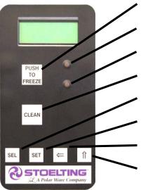
F. LEDS
The membrane switch (touchpad) features two lights: a green LED and an amber LED. The green LED is lit during "Serve Mode". During freeze down, it is not lit. When product consistency approaches 75% in the freezing cylinder, the green LED flashes. The amber LED is on during all other modes. Both LEDs alternatively flash if an error occurs or if the freezing cylinder is off.
G. CLEAN BUTTON
The CLEAN button is a membrane, or snap switch. When the button is pressed, the freezing cycle stops and the drive motor will start. A CLEAN message will display on the LCD screen along with a 5-minute countdown timer. To exit the CLEAN mode, turn the Freezing Cylinder OFF/ON switch to the OFF position or press the CLEAN button again. If the machine is left in CLEAN for more than 20 minutes, an error code (E4) will be displayed on the display panel. Place the Freezing Cylinder OFF/ON switch in the OFF position and back in the ON position to clear this error.
Push to Freeze
Green LED
Amber LED
Clean Button
SEL Button
SET Button
Left Arrow Button
Up Arrow Button
Figure 3-2 IntelliTec Control
H. DRIVE MOTOR OVERLOAD
The internal drive motor overload will trip if the drive motor is overloaded. It will reset after approximately 10-12 minutes. If the drive motor continues to trip, refer to Troubleshooting in Section 7.
I. MIX LOW LIGHT INDICATOR
A MIX LOW message will appear on the LCD display to alert the operator of a low mix condition. The message will display when there is approximately one gallon of mix left in the hopper. When the MIX LOW message is displayed, refill the hopper immediately.
L. MENU NAVIGATION BUTTONS
The Menu Navigation Buttons allow the user to display information regarding the machine’s status of operation as well as adjust product consistency (Fig. 3-2).
Selection Button (SEL) The SEL button is used in combination with the up arrow button to enter into the settings of the IntelliTec control. This button is also used to navigate through the control settings menu.
Set Button (SET) The SET button is used to save a change made to the product consistency setting. It is also used to save changes when modifying control settings.
Left Arrow Button ( ) If the left arrow button is pressed for 5 seconds, the display will remain lit. To turn the light off, press the left arrow button for 5 seconds. The left arrow button is used primarily to navigate through the control settings.
Up Arrow Button ( ) After pressing the SET button, the up arrow button will change the value of the product consistency setting. This button is also used to navigate through the control settings.
12
3.3IMPORTANTINFORMATIONREGARDINGCLEANING ANDSANITIZING
Soft serve machines require special consideration when it comes to food safety and proper cleaning and sanitizing.
The following information specifically covers issues for cleaning and sanitizing frozen dessert machines. This information is meant to supplement a comprehensive food safety program.
SOIL MATERIALS ASSOCIATED WITH FROZEN DESSERT MACHINES
MILKFAT/BUTTERFAT – As components of ice-cream/ frozen custard mix, these soils will accumulate on the interior surfaces of the machine and its parts. Fats are difficult to remove and help attribute to milkstone buildup.
MILKSTONE – Is a white/gray film that forms on equipment and utensils that are exposed to dairy products. These films will accumulate slowly on surfaces because of ineffective cleaning, use of hard water, or both. Milkstone is usually a porous deposit, which will harbor microbial contaminants and eventually defy sanitizing efforts.
Once milkstone has formed, it is very difficult to remove. Without using the correct product and procedure, it is nearly impossible to remove a thick layer of milkstone.
(NOTE: general-purpose cleaners DO NOT remove milkstone.) This can lead to high bacteria counts and a food safety dilemma.
IT IS BEST TO CONTROL MILKSTONE ON A DAILY BASISBEFOREITCANBECOMEASIGNIFICANTFOOD SAFETY PROBLEM.
In addition to food safety, milkstone can cause premature wear to machine parts, which can add to costs for replacement parts or possibly more expensive repairs if worn machine parts are not replaced once they have become excessively worn.
IMPORTANT DIFFERENCES BETWEEN CLEANING AND SANITIZING
CLEANING vs. SANITIZING
It is important to distinguish between cleaning and sanitizing. Although these terms may sound synonymous, they are not. BOTH are required for adequate food safety and proper machine maintenance.
CLEANING
·Is the removal of soil materials from a surface.
·Is a prerequisite for effective sanitizing.
NOTE
An UNCLEAN surface will harbor bacteria that can defy sanitizing efforts.
Bacteria can develop and resist sanitizing efforts within a layer of soil material (milkstone). Thorough cleaning procedures that involve milkstone removal are critical for operators of frozen dessert machines.
SANITIZING
·Kills bacteria.
·Can be effective on clean surfaces only.
NOTE
Using a SANITIZER on an unclean surface will not guarantee a clean and safe frozen dessert machine.
PROPER DAILY MAINTENANCE:
The Only Way to Assure Food Safety and Product Quality
Proper daily maintenance can involve a wide variety of products and procedures. Overall, the products and procedures fall into three separate categories. (Please note that this is a brief overview intended for informational purposes only.)
1.CLEANING – This involves draining mix from the freezing cylinder and rinsing the machine with water. Next, a cleaner is run through the machine. Then,themachineisdisassembledandremovable parts are taken to the sink for cleaning.
2.MILKSTONE REMOVAL – Since most cleaners do not have the ability to remove milkstone, the use of a delimer becomes necessary. Although this procedure may not be needed on a daily basis, it will usually follow the cleaning procedure. It requires letting a delimer solution soak in the machine for an extended period. Individual parts are also soaked in a deliming solution for an extended period of time (more about delimers in Additional Information).
3.SANITIZING–Afterthemachinehasbeencleaned and contains no milkstone, the machine is reassembled. Then a FDA-approved sanitizing solution is run through the machine to kill bacteria. The machine is then ready for food preparation.
As a recommended cleaner and sanitizer for your frozen dessert machine, STERA-SHEEN has proven to be one of the best daily maintenance products for:
·CLEANING – Thorough removal of all solids including butterfat and milk fat.
·MILKSTONE REMOVAL – Complete removal of milkstone.
·SANITIZING – FDA-approved no rinse sanitizer for food contact surfaces.
ADDITIONAL INFORMATION
THE USE OF DELIMERS
A delimer is a strong acid that has the ability to dissolve milkstone. This type of chemical may become necessary once high levels of milkstone have developed. While these products are very effective for removing HIGH levels of milkstone, they are not ideal for two reasons:
1.PRODUCTSAFETY–Strongacidsaredangerous chemicals. Carefully follow safety instructions provided with delimer products.
13
 Loading...