


Model E112 / F112
SERVICE MANUAL
Manual No. 513632 |
Rev.3 |

This manual provides basic information about the machine. Instructions and suggestions are given covering its operation and care.
The illustrations and specifications are not binding in detail. We reserve the right to make changes to the machine without notice, and without incurring any obligation to modify or provide new parts for machines built prior to date of change.
DO NOT ATTEMPT to operate the machine until instructions and safety precautions in this manual are read completely and are thoroughly understood. If problems develop or questions arise in connection with installation, operation, or servicing of the machine, contact Stoelting.
|
Stoelting Foodservice Equipment |
Customer Service: 888.429.5920 |
|
502 Highway 67 |
Fax: 800.545.0662 |
|
||
|
Kiel, WI 53042-1600 |
Email: foodservice@stoelting.com |
|
||
|
U.S.A. |
|
stoeltingfoodservice.com
Main Tel: 800.558.5807 |
© 2014 PW Stoelting, LLC |
Fax: 920.894.7029 |
|
|
|

A Few Words About Safety
Safety Information
Read and understand the entire manual before operating or maintaining Stoelting equipment.
This manual provides the operator with information for the safe operation and maintenance of Stoelting equipment. As with any machine, there are hazards associated with their operation. For this reason safety is emphasized throughout the manual. To highlight specific safety information, the following safety definitions are provided to assist the reader.
The purpose of safety symbols is to attract your attention to possible dangers. The safety symbols, and their explanations, deserve your careful attention and understanding. The safety warnings do not by themselves eliminate any danger. The instructions or warnings they give are not substitutes for proper accident prevention measures.
If you need to replace a part, use genuine Stoelting parts with the correct part number or an equivalent part. We strongly recommend that you do not use replacement parts of inferior quality.
Safety Alert Symbol:
This symbol Indicates danger, warning or caution. Attention is required in order to avoid serious personal injury. The message that follows the symbol contains important information about safety.
Signal Word:
Signal words are distinctive words used throughout this manual that alert the reader to the existence and relative degree of a hazard.
 WARNING
The signal word “WARNING” indicates a potentially hazardous situation, which, if not avoided, may result in death or serious injury and equipment/property damage.
 CAUTION
The signal word “CAUTION” indicates a potentially hazardous situation, which, if not avoided, may result in minor or moderate injury and equipment/property damage.
CAUTION
The signal word “CAUTION” not preceded by the safety alert symbol indicates a potentially hazardous situation, which, if not avoided, may result in equipment/property damage.
NOTE (or NOTICE)
The signal word “NOTICE” indicates information or procedures that relate directly or indirectly to the safety of personnel or equipment/property.

|
TABLE OF |
|
|
CONTENTS |
|
Section |
Description |
Page |
1 |
Description and Specifications |
|
1.1 |
Description.................................................................................................. |
1 |
1.2 |
Specifications ............................................................................................. |
2 |
1.3 |
Modes of Normal Operation ....................................................................... |
4 |
1.4 |
Operation During an Error Mode ................................................................ |
5 |
2 |
Installation Instructions |
|
2.1 |
Safety Precautions ..................................................................................... |
7 |
2.2 |
Shipment and Transit.................................................................................. |
7 |
2.3 |
Machine Installation.................................................................................... |
7 |
3 |
Initial Set-Up and Operation |
|
3.1 |
Operator’s Safety Precautions ................................................................... |
9 |
3.2 |
Operating Controls and Indicators ............................................................. |
9 |
3.3 |
Sanitizing .................................................................................................... |
10 |
3.4 |
Freeze Down and Operation ...................................................................... |
11 |
3.5 |
Mix Information ........................................................................................... |
11 |
3.6 |
Removing Mix From Machine..................................................................... |
12 |
3.7 |
Cleaning the Machine................................................................................. |
12 |
3.8 |
Disassembly of Machine Parts ................................................................... |
12 |
3.9 |
Cleaning and Sanitizing the Machine Parts................................................ |
13 |
3.10 |
Sanitize Machine ........................................................................................ |
13 |
3.11 |
Assembly of Machine ................................................................................. |
14 |
3.12 |
Routine Cleaning ........................................................................................ |
15 |
3.13 |
Preventive Maintenance ............................................................................. |
15 |
3.14 |
Extended Storage....................................................................................... |
17 |
4 |
Maintenance and Adjustments |
|
4.1 |
Machine Adjustment ................................................................................... |
19 |
4.2 |
Product Consistency Adjustment................................................................ |
19 |
4.3 |
Convert Slush to Shake.............................................................................. |
19 |
4.4 |
Drive Belt Tension Adjustment.................................................................... |
19 |
4.5 |
Condenser Cleaning................................................................................... |
19 |
4.6 |
Preventative Maintenance .......................................................................... |
20 |
4.7 |
Extended Storage....................................................................................... |
20 |

Section |
Description |
Page |
5 |
Refrigeration System |
|
5.1 |
Refrigeration System .................................................................................. |
21 |
5.2 |
Refrigerant Recovery and Evacuation........................................................ |
21 |
5.3 |
Refrigerant Charging .................................................................................. |
22 |
5.4 |
Compressor ................................................................................................ |
22 |
5.5 |
Condenser .................................................................................................. |
24 |
5.6 |
Valves ......................................................................................................... |
24 |
5.7 |
Capillary Tube............................................................................................. |
27 |
5.8 |
Filter Drier................................................................................................... |
28 |
6 |
Electrical and Mechanical Control Systems |
|
6.1 |
Control Board ............................................................................................. |
29 |
6.2 |
Contactor .................................................................................................... |
29 |
6.3 |
Drive Motor ................................................................................................. |
30 |
6.4 |
Capacitors .................................................................................................. |
31 |
6.5 |
Gearbox...................................................................................................... |
32 |
6.6 |
Condenser Fan Motor (Air-Cooled Only).................................................... |
32 |
6.7 |
Switches ..................................................................................................... |
32 |
7 |
Troubleshooting |
|
7.1 |
Light Indicators ........................................................................................... |
35 |
7.2 |
Troubleshooting.......................................................................................... |
35 |
8 |
Replacement Parts |
|
8.1 |
Decals, Lubrication, Panels & Legs............................................................ |
37 |
8.2 |
Auger Shaft and Faceplate Parts ............................................................... |
38 |
8.3 |
Hopper Parts .............................................................................................. |
40 |
8.4 |
Machine Front & Spigot Switch Assembly .................................................. |
41 |
8.5 |
E112 Parts .................................................................................................. |
42 |
8.6 |
F112 Parts .................................................................................................. |
44 |
8.7 |
Retrofit Kits ................................................................................................. |
46 |
8.8 |
Refrigeration Diagram ................................................................................ |
47 |
8.9 |
E112 Wiring Diagram.................................................................................. |
48 |
8.10 |
F112 Wiring Diagram.................................................................................. |
50 |
8.11 |
Autofill Options ........................................................................................... |
52 |

SECTION 1
DESCRIPTION AND SPECIFICATIONS
1.1DESCRIPTION
The Stoelting E112/F112 counter machines are gravity fed. The machines are equipped with fully automatic controls to provide a uniform product. They will operate with almost any type of shake or frozen beverage mix. This manual is designed to help qualified service personnel and operators with the installation, operation and maintenance of the Stoelting E112/F112 gravity machines.
Figure 1-1 Model E112
Figure 1-1 Model F112
Service Manual #513632 |
1 |
E112/F112 Model Machines |

1.2 SPECIFICATIONS
E112
F112
Figure 1-2 Specifications
Service Manual #513632 |
2 |
E112/F112 Model Machines |

1.2SPECIFICATIONS - CONTINUED
|
|
Model E112 |
Model F112 |
|||||
Dimensions |
Machine |
with crate |
Machine |
|
with crate |
|||
width |
15-1/4’’ (38,7 cm) |
17-1/2’’ (44,5 cm) |
17-1/4’’ (43,8 cm) |
|
29’’ (73,7 cm) |
|||
height |
30-1/2’’ (77,5 cm) |
35’’ (88,9 cm) |
33’’ (83,8 cm) |
|
44’’ (111,8 cm) |
|||
depth |
32’’ (81,3 cm) |
36-1/2’’ (92,7 cm) |
30-1/4’’ (76,8 cm) |
|
39’’ (99,1 cm) |
|||
Weight |
205 lbs (92,9 kg) |
215 lbs (97,5 kg) |
288 lbs (130,6 kg) |
315 lbs (142,8 kg) |
||||
Electrical |
1 Phase, 115 VAC, 60Hz |
1 Phase, 208-240 VAC, 60Hz |
||||||
running amps |
16A |
10A |
||||||
connection type |
NEMA5-20P power cord provided |
NEMA6-15P power cord provided |
||||||
International Option |
1 Phase, 220-240 VAC, 50Hz |
1 Phase, 220-240 VAC, 50Hz |
||||||
Compressor |
6,000 Btu/hr |
8,600 Btu/hr |
||||||
Drive Motor |
1/3 hp |
3/4 hp |
||||||
|
|
Air cooled units require 3” (7,6 cm) air |
|
|
|
|||
Air Flow |
space on both sides or 4” |
Air cooled units require 6” (15,24 cm) |
||||||
(10,2 cm) air space in back |
air space on both sides |
|||||||
|
|
|||||||
|
|
for side-by-side installation |
|
|
|
|||
Plumbing Fittings |
N/A |
Water cooled units require 3/8” N.P.T. |
||||||
water and drain fittings. |
||||||||
|
|
|
|
|
||||
Hopper Volume |
3.625 gallon (13,73 liters) |
5.375 gallon (20,35 liters) |
||||||
Freezing Cylinder |
1.25 gallon (4,73 liters) |
2.125 gallon (8,04 liters) |
||||||
Volume |
||||||||
|
|
|
|
|
|
|||
Production Capacity |
18 GPH (68,15 liters) |
24 GPH (90,87 liters) |
||||||
|
|
|
|
|
|
|
|
|
|
|
|
|
|
|
|
||
|
|
|
|
E112 |
|
|
||
|
|
Refrigerant |
|
R-404A |
|
|
||
|
|
Charge |
|
20 oz |
|
|
||
|
Suction Pressure |
|
Shake 22-24 psig |
|
|
|||
|
|
(at 72°F) |
|
Slush 30-32 psig |
|
|
||
|
Discharge Pressure |
|
Shake 205-215 psig |
|
|
|||
|
|
Slush 200-205 psig |
|
|
||||
|
|
|
|
|
|
|||
|
|
EPR Valve |
|
59-61 psig |
|
|
||
|
|
|
|
|
|
|
|
|
|
|
|
|
F112 |
|
|
||
|
|
Refrigerant |
|
R-404A |
|
|
||
|
|
Charge |
|
(W/C) 20 oz |
|
|
||
|
|
|
(A/C) 28 oz |
|
|
|||
|
|
|
|
|
|
|||
|
Suction Pressure |
|
Shake 30-32 psig |
|
|
|||
|
|
(at 72°F) |
|
Slush 40 psig |
|
|
||
|
Discharge Pressure |
|
Shake 245-250 psig |
|
|
|||
|
|
Slush 280 psig |
|
|
||||
|
|
|
|
|
|
|||
|
|
EPR Valve |
|
59-61 psig |
|
|
||
Service Manual #513632 |
3 |
E112/F112 Model Machines |

1.3MODES OF NORMAL OPERATION
Following is an explanation of the normal operation modes on the E112 and F112 (Refer to Figure 1-3).
NOTE
The following modes of operation are for the latest versions of the control boards (521696.3, 521696.2 and 521696.1 Rev72). The older version of the control has the following differences:
•The older control does not have slush mode with a continuous drive
•The older control does not have a consistency check during the pre stir in slush mode and the pre stir is 3 seconds (instead of 4)
•The older control runs strictly on timers during an error mode, and the cycle time during a drive motor error is 7 minutes off/55 seconds on.
NOTE
Slush mode has two options: normal and continuous drive. With the continuous drive option selected, the drive motor will run at all times, including standby. To change the control between the two options, refer to Section 4.3.
A. PRE STIR
When the CLEAN-OFF-ON is moved into the ON position or when the spigot is opened, the drive motor will start a 4-second pre stir. In slush mode, a consistency check will determine if a freezing cycle will begin.
B. FREEZING CYCLE
After the pre stir, a freezing cycle begins. The freezing cycle continues until the torque rod closes the torque switch and keeps the switch closed for 3 seconds. If
product consistency is not met within 22 minutes for slush or 20 minutes for shake, the machine will operate in the compressor time out mode (See Section 1.4).
NOTE
If the spigot is pulled during a freezing cycle, the 20-minute or 22-minute timer will restart.
C. POST STIR
After the freezing cycle ends, the drive motor will continue to run for an 18 second post stir. The post stir ensures the product does not freeze to the cylinder. If the spigot is opened during the post stir, the machine will check consistency. If the product is at consistency, the machine will move into standby. If the product is not at consistency, the machine will start a freezing cycle.
D. STANDBY
After the post stir, the machine will be in standby. It will remaininstandbyfor7 minutesoruntilthespigotisopened.
E. DEFROST MODE (SLUSH MODE ONLY)
If the spigot is not opened for 3 hours, defrost mode will begin. The drive motor will run for 90 seconds every 7 minutes and the diagnostic light will remain lit.
After 5.5 hours or if the spigot is opened, normal operation mode will begin.
F. CLEAN MODE
When the CLEAN-OFF-ON switch is in the CLEAN position, the drive motor starts and will run for 20 minutes. After the 20 minutes expire, the drive motor will stop and the diagnostic light will flash three times every 4 seconds. It will continue to flash until the CLEAN-OFF-ON switch is moved out of the CLEAN position.
Figure 1-3 Modes of Normal Operation
Service Manual #513632 |
4 |
E112/F112 Model Machines |
Figure 1-4 Compressor Time Out Mode
1.4 OPERATION DURING AN ERROR MODE
A. COMPRESSOR TIME OUT MODE
If the freezing cycle exceeds 20 minutes for shake or 22 minutes for slush, the machine will operate on timers. The diagnostic light will flash once every 4 seconds (Refer to Figure 1-4).
B. LOW MIX MODE
If the mix level falls below the sensor probe, the machine will operate on timers. The ADD MIX light will flash. The machine will continue to operate on timers until the mix level in the hopper is above the sensor probe (Refer to Figure 1-5).
Figure 1-5 Low Mix Mode
Service Manual #513632 |
5 |
E112/F112 Model Machines |
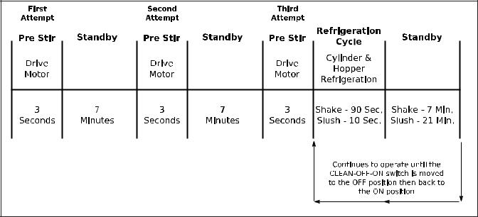
Figure 1-6 Drive Motor Error Mode
C. DRIVE MOTOR ERROR MODE
If the control does not sense current from the drive motor during a pre stir, the machine will go into standby mode for 7 minutes. After standby, the control will repeat the pre stir and attempt to sense drive motor current. After the third pre stir without sensing drive motor current, the machine will operate on timers and the diagnostic light will flash twice every four seconds (Refer to Figure 1-6). The attempts to sense the drive motor current can be substituted by pulling the spigot.
Service Manual #513632 |
6 |
E112/F112 Model Machines |

SECTION 2
INSTALLATION INSTRUCTIONS
2.1 SAFETY PRECAUTIONS
Do not attempt to operate the machine until the safety precautions and operating instructions in this manual are read completely and are thoroughly understood.
Take notice of all warning labels on the machine. The labels have been put there to help maintain a safe working environment. The labels have been designed to withstand washing and cleaning. All labels must remain legible for the life of the machine. Labels should be checked periodically to be sure they can be recognized as warning labels.
If danger, warning or caution labels are needed, indicate the part number, type of label, location of label, and quantity required along with your address and mail to:
STOELTING, INC.
ATTENTION: Customer Service
502 Hwy. 67
Kiel, Wisconsin 53042
2.2 SHIPMENT AND TRANSIT
Themachinehasbeenassembled,operatedandinspected at the factory. Upon arrival at the final destination, the entire machine must be checked for any damage which may have occurred during transit.
With the method of packaging used, the machine should arrive in excellent condition. THE CARRIER IS RESPONSIBLE FOR ALL DAMAGE IN TRANSIT, WHETHER VISIBLE OR CONCEALED. Do not pay the freight bill until the machine has been checked for damage. Have the carrier note any visible damage on the freight bill. If concealed damage and/or shortage is found later, advise the carrier within 10 days and request inspection. The customer must place claim for damages and/or shortages in shipment with the carrier. Stoelting, Inc. cannot make any claims against the carrier.
2.3 MACHINE INSTALLATION
Installation of the machine involves moving the machine close to its permanent location, removing all crating, setting in place, assembling parts, and cleaning.
A.Uncrate the machine.
B.Accuratelevelingisnecessaryforcorrectdrainage of machine barrel and to insure correct overrun. Place a bubble level on top of the machine at each corner to check for level condition. If adjustment is necessary, level the machine by turning the bottom part of each leg in or out.
C.The F112 has a base gasket that must be installed. Separate the gasket and install it with the seam to the back. Make sure the angled side of the gasket is facing up.
Figure 2-2 Space and Ventilation Requirements
D.Correct ventilation is required. The E112 requires 3” clearance on both sides. If the machine is placed side-by-side next to other equipment, there needs to be at lease 4” clearance at the back of the machine. The air-cooled F112 requires 6” clearance on both sides for proper air flow.
CAUTION
Failure to provide adequate ventilation will void warranty.
D.Connect the drip tray bracket by loosening the two screws at the front of the machine. Install the bracket so that it rests on the nylon washer between the two metal washers. Tighten the screws.
Figure 2-3 Drip Tray Bracket
E.Place the CLEAN-ON-OFF switch in the OFF position.
Service Manual #513632 |
7 |
E112/F112 Model Machines |

 WARNING
Do not alter or deform electrical plug in any way. Altering the plug to fit into an outlet of different configuration may cause fire, risk of electrical shock, product damage and will void warranty.
E.Connect the power cord to the proper power supply. The plug on the E112 is designed for 115VAC, 20 amp duty and the plug on the F112 is designed for 208-240VAC / 15 amp duty. Check the nameplate on your machine for proper supply. Theunitmustbeconnectedtoaproperlygrounded receptacle. The electrical cord furnished as part of the machine has a three prong grounding type plug. The use of an extension cord is not recommended, if necessary use one with a size 12 gauge or heavier with ground wire. Do not use an adapter to get around grounding requirement.
Service Manual #513632 |
8 |
E112/F112 Model Machines |

SECTION 3
INITIAL SET-UP AND OPERATION
3.1 OPERATOR’S SAFETY PRECAUTIONS
SAFE OPERATION IS NO ACCIDENT; observe these rules:
A.Know the machine. Read and understand the Operating Instructions.
B.Notice all warning labels on the machine.
C.Wear proper clothing.Avoid loose fitting garments, and remove watches, rings or jewelry that could cause a serious accident.
D.Maintain a clean work area. Avoid accidents by cleaning up the area and keeping it clean.
E.Stay alert at all times. Know which switch, push button or control you are about to use and what effect it is going to have.
F.Disconnect electrical cord for maintenance. Never attempt to repair or perform maintenance on the machine until the main electrical power has been disconnected.
G.Do not operate under unsafe operating conditions. Neveroperatethemachineifunusualorexcessive noise or vibration occurs.
3.2 OPERATING CONTROLS AND INDICATORS
Before operating the machine, it is required that the operator know the function of each operating control. Refer to Figure 3-1 for the location of the operating controls on the machine.
 WARNING
High voltage will shock, burn or cause death. The OFF-ON switch must be placed in the OFF position prior to disassembling for cleaning or servicing. Do not operate machine with cabinet panels removed.
A.Spigot Switch
The spigot switch will automatically start the auger drive and refrigeration systems when the spigot is opened to dispense product. When the spigot is closed, the drive motor and compressor will remain on until the product in the freezing cylinder reaches the proper consistency..
Diagnostic
Light
Consistency
Adjustment
Screw Add Mix
Indicator
Clean/Off/On
Switch
Figure 3-1 Controls
Service Manual #513632 |
9 |
E112/F112 Model Machines |

B.CLEAN-OFF-ON Switch
The CLEAN-OFF-ON switch is used to supply power to the control circuit. When the switch is in the OFF (middle) position, power will not be supplied to the control board or refrigeration system. When the switch is in the ON position, the machine will operate in the freezing mode. When the switch is in the CLEAN position, all refrigeration will stop and the auger will start rotating.
C.ADD MIX Light
The ADD MIX light will flash to alert the operator to a low mix condition. It does so by monitoring the mix level in the hopper. When the ADD MIX light is flashing, refill hopper immediately.
NOTE
Failure to refill hopper immediately may result in operational problems.
D.Diagnostic Light
The Diagnostic Light will flash if an error occurs. The light will flash once if there is a compressor error. There will be two quick flashes if there is an auger error. And there will be three quick flashes if the machine is left in clean mode for more than 20 minutes. Refer to the troubleshooting section for details.
E.Consistency Adjustment Screw
The Consistency Adjustment Screw increases or decreases product consistency.Atension spring is connected to the screw and changes the amount of torque needed to complete a refrigeration cycle. Turn the knob clockwise to increase consistency or counterclockwise to decrease consistency.
NOTE
An additional spring is included with the machine behind the header panel. The additional spring can be installed for use with shake mixes when a higher consistency is required. Do not use the optional spring with slush mixes.
F.Front Door Safety Switch
The front door safety switch prevents the auger from turning when the front door is removed. The switch is open when the door is not in place and closed when the door is properly installed.
G.Autofill Kit - Optional (E112 Part 2183807, F112 Part 2187101)
The autofill kit is used with a pump to keep the hopper filled. The autofill kit is for use with nonpotentially hazardous food substances; non-dairy. Refer to Section 5-4 for Autofill options.
H.Light Kit - Optional (E112 Part 2183800, F112 Part 2187102)
The light kit is installed behind the header panel and illuminates a translucent header panel.
I.Bottle Rack Kit - Optional (E112 Part 2187100, F112 Part 2187040 or 2187024)
The bottle rack kit is installed onto the header panel and holds 7 flavor bottles (13 bottles on the 2187024).
J.Spinner Kit - Optional (E112 Part 2187103, F112 Part 2187031)
The spinner kit is installed on the front of the machine and offers blended frozen beverages.
3.3 SANITIZING
Sanitizing must be done after the machine is cleaned and just before the hopper is filled with mix. Sanitizing the night before is not effective. However, you should always clean the machine and parts after each use.
The United States Department of Agriculture and the Food and Drug Administration require that all cleaning and sanitizing solutions used with food processing equipment be certified for this use.
When sanitizing the machine, refer to local sanitary regulations for applicable codes and recommended sanitizing products and procedures. The frequency of sanitizing must comply with local health regulations.
Mix sanitizer according to manufacturer’s instructions to provide a 100 parts per million (ppm) strength solution and check the solution with chlorine test strips. Mix sanitizer in quantities of no less than 2 gallons (7.5 liters) of 90° to 110°F (32° to 43°C) water. Allow sanitizer to contact the surfaces to be sanitized for 5 minutes. Any sanitizer must be used only in accordance with the manufacturer’s instructions.
CAUTION
Do not allow sanitizer to remain in contact with stainless steel parts for prolonged periods. Prolonged contact of sanitizer with machine may cause corrosion of stainless steel parts.
In general, sanitizing may be conducted as follows:
A.Prepare Stera-Sheen Green Label Sanitizer or equivalent according to manufacturer’s instructionstoprovidea100ppmstrengthsolution. Mix the sanitizer in quantities of no less than 2 gallons of 90° to 110°F (32° to 43°C) water. Check the strength of the sanitizing solution. Use a chlorine test strip and color chart to make sure the solution has 100 ppm. Any sanitizer must be used only in accordance with the manufacturer’s instructions.
Service Manual #513632 |
10 |
E112/F112 Model Machines |

Figure 3-2 Mix Inlet Regulator
B.If using a shake mix, place the mix inlet regulator into hopper (Refer to Figure 3-2). If using a slush mix, the mix inlet regulator is not required.
C.Pour the sanitizing solution into the hopper and place the switch in the CLEAN position. Check for leaks.
D.Clean sides of hopper, mix inlet regulator and underside of hopper cover using a soft bristle brush dipped in the sanitizing solution (Refer to Figure 3-3).
Figure 3-3 Sanitizing hopper
E.After five minutes, place a bucket under the spigot and open spigot to drain most sanitizing solution. Leave a small amount of the sanitizing solution in the freezing cylinder. Place the switch in the OFF (middle) position.
F.Collect the remaining sanitizing solution in a cup and test the chlorine contents with a new test strip. A reading of 100 ppm or more is acceptable.
If the reading is less than 100 ppm, sanitize the machine again.
If the reading is less than 100 ppm after sanitizing the second time, disassemble and wash the machine again.
3.4 FREEZE DOWN AND OPERATION
This section covers the recommended operating procedures for the safe operation of the machine.
A.Sanitize just prior to use.
B.Place the switch in the OFF (middle) position.
NOTE
Make sure the mix inlet regulator is in place before adding shake mixes. This is not necessary for slush mixes.
C.Pour approximately 1/2 gallon of fully thawed mix into the hopper. Open spigot and drain a small amount of mix to remove any remaining sanitizer.
D.Fill the hopper with pre-chilled (40°F or 4°C) mix.
NOTE
Do not overfill the hopper. Mix level must be below the air inlet tube on the mix inlet regulator.
E.Place the switch in the ON position.
NOTE
After the drive motor starts, there is a 3 or 4 second delay before the compressor starts.
F.After 8 to 12 minutes the product will be at consistency and will be ready to serve. Freeze down time may vary depending on mix type and ambient temperatures.
G.To dispense, pull the spigot handle down to open the spigot.
H.The machine is designed to dispense the product at a reasonable draw rate. If the machine is overdrawn, the result is a soft product or a product that will not dispense at all. If this should occur, allow the machine to run for approximately 30 seconds before dispensing additional product.
I.Do not operate the machine when the ADD MIX light is on. Refill the hopper immediately.
3.5 MIX INFORMATION
Mix can vary considerably from one manufacturer to another. Differences in the amount of butterfat content and quantity and quality of other ingredients have a direct bearing on the finished frozen product. A change in machine performance that cannot be explained by a technical problem may be related to the mix.
Proper product serving temperature varies from one manufacturer’s mix to another. Shake and stackable slush mixes provide satisfactory product from 24° to 28°F (-4° to -2°C).
When checking the temperature, stir the thermometer in the frozen product to obtain an accurate reading.
Service Manual #513632 |
11 |
E112/F112 Model Machines |
Old mix or mix that has been stored at elevated temperatures will produce poor-quality product with a bad taste and unacceptable appearance. To retard bacteria growth in dairy based mixes, the best storage temperature range is between 33° to 38°F (0.5° to 3.3°C).
Some shake mixes tend to foam more than others. If foam appears in the hopper, skim off with a sanitized utensil and discard. Periodically, stir the mix in the hopper with a sanitized utensil to help prevent excess foam.
3.6 REMOVING MIX FROM MACHINE
To remove the mix from the machine, refer to the following steps:
A.If removing shake mix, pull the mix inlet regulator straight up and remove it from the hopper.
B.Place the switch in the CLEAN position to rotate the auger. Allow the mix to agitate in freezing cylinder until the mix has become liquid, about 5 minutes.
C.Drain the liquid mix by opening the spigot. A container should be placed under the spigot to collect the liquid mix.
D.Place the switch in the OFF (middle) position.
3.7 CLEANING THE MACHINE
NOTE
The frequency of cleaning the machine and machine parts must comply with local health regulations.
After the mix has been removed from the machine, the machine must be cleaned. To clean the machine, refer to the following steps:
A.Close the spigot and fill the hopper with 2 gallons (8 liters) of tap water.
B.Place the switch in the CLEAN position.The auger will start to rotate.
C.Allow the water to agitate for approximately 30 seconds.
D.Open the spigot to drain the water. Remember to place a container under the spigot to catch the water. When the water has drained, place the switch in the OFF (middle) position. Allow the freezing cylinder to drain completely.
E.Prepare sanitizing solution according to manufacturer’s instructions to provide a 100 ppm strength solution. Mix the sanitizer in quantities of no less than 2 gallons of 90° to 110°F (32° to 43°C) water. Check the strength of the sanitizing solution. Use a chlorine test strip and color chart to make sure the solution has 100 ppm. Repeat steps A through D using the sanitizing solution.
3.8 DISASSEMBLY OF MACHINE PARTS
Inspection for worn or broken parts should be made each time the machine is disassembled. All worn or broken parts should be replaced to ensure safety to both the operator and the customer and to maintain good machine performance and a quality product. Frequency of cleaning must comply with the local health regulations.
To disassemble the machine, refer to the following steps:
 CAUTION
Hazardous Moving Parts.
Revolving auger shaft can grab and cause injury. Place the switch in the OFF (middle) position before disassembling for cleaning or servicing.
A.Remove hopper cover. Remove the mix inlet regulator from the hopper (if installed).
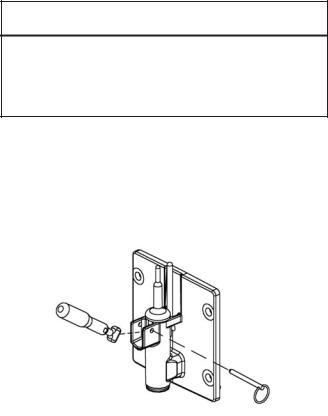
B.Pull out the spigot pin by its ring (Refer to Figure 3-4).
Figure 3-4 Remove Spigot Pin
C.Remove the spigot handle.
D.Remove front door by turning the circular knobs and then pulling door off the studs.
NOTE
When removing front door, entire door and stator assembly will come out as well.
E.Remove torque rod from stator assembly.
F.Remove quad ring from groove in front door.
G.Remove stator bar. Remove o-ring and white bushing from stator bar.
H.Remove auger support bushing.
I.Turn the spigot body until the ice breaker bar can be removed. Remove breaker bar (Refer to Figure 3-5).
Service Manual #513632 |
12 |
E112/F112 Model Machines |
 Loading...