


HARMONY LA300
Service Technical Section
W764332-307
REVISION RECORD
Rev. |
Revision |
PER/RA/ECA |
Changed |
Engr’g |
Manuf’g |
Num. |
Date |
Number |
By |
Approval |
Approval |
0 |
10/07/05 |
MFEF05-086 |
|
GJK |
|
|
|
|
|
|
|
CONTENTS PAGE
Theory of Operation ………………………………………2
LA300 Troubleshooting………………………………….. 6
LA300 Field Test Procedure………………………………8
STERIS LA 300 PM Schedule……………………………11
HARMONY LA300
Service Technical Section
W764332307
B/P Date: 10/07/05 Rev.0
Page 1 of 11

HARMONY LA300
Service Technical Section
Theory of Operation
The Harmony LA300 Exam Surgical Lighting System is offered to complement other existing Harmony systems such as Harmony EMS and Harmony LA/LL Lights. In order to avoid confusion between products, it will be necessary to utilize the full product name when communicating. The LA300 exam light is intended to be a high quality exam light, to complement the Exam 10 product line (not replace it).
The Harmony LA300 suspension system is available in several configurations;
1.Surgical/OR setting (LA08). The lighting system can be installed as part of a traditional Harmony LA suspension system. All that is required is an available, open suspension arm on the main LA spindle assembly. The LA300 light can be added at a later date, but first an existing light head and spring arm would need to be removed and the 300 spring arm and light head substituted in its place, or if the spindle has a spacer installed, then an Add on arm kit (1893219D) can be ordered to install ANY style of LA spring arm. (A sales kit is available that includes a LA300 spring arm and a light head.
2.Ceiling Mount (LA30) The ceiling mount option contains a suspension system unique to the LA300. It is manufactured by Ondal Corporation and contains all metric components. The system consists of a horizontal tube, vertical tube, spring arm, DC power supply and light head. The mounting bolt pattern is retro-fixable to Exam 10 locations. Maximum ceiling height is 10’ and minimum is 7’ 10”. The light weighs 100 pounds plus moment force ( see equipment drawing).The ceiling flange will be secured to the customer’s structure via four 1/4” bolts or all thread.
3.Wall Mount (LA31) The wall mount option contains a wall bracket and power supply cover, a horizontal arm, a spring arm, and a light head. The DC power supply is located on the wall, beneath a plastic cover. The light weighs 55 pounds plus moment force (see equipment drawing).
4.Mobile Stand (LA32) The mobile option contains a base with power supply, a vertical support tube, a spring arm and Light head. Power cord is 20 feet long, weight is approximately 76 pounds.
5.Controls: The control system characteristics are as follows;
5.1.Controls -There is no wall control for any of the suspension options, however this light head and spring arm can be added to a traditional LA suspension system, within an OR room. This option is very uncommon, but if present, would utilize the standard Harmony LA wall control family. There is a bezel/switch assembly located on the light head for
HARMONY LA300
Service Technical Section
W764332307
B/P Date: 10/07/05 Rev.0
Page 2 of 11
HARMONY LA300 Service Technical Section
the surgeon intensity control. This bezel switch sends a signal to the light head circuit board, which turns on DC power to the lamp.
5.2.Power Supply - All units are equipped with a 24VDC power supply located under the canopy for the ceiling and wall mount versions. It is located in the base of the Mobile Stand. The power supply is 24 VDC, maximum 200 Watt output. Black wire output is DC ground and White wire output is +24VDC. The power supply is designed to “fold back” its output to a low voltage level in the event that a short circuit exists across its output.
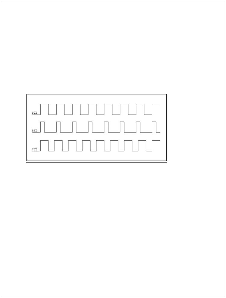
5.3.Light Head Control Board - The circuit board within the LA 300 Light head controls the power of the lamp output similar to the power control circuits on LA500/700. The intensity of the lamp is controlled by changing the duty cycle of the voltage going to the lamp as follows;
Figure 1-HARMONY LA LIGHT DUTY CYCLE
5.4.Lamp Power Explanation – The power being supplied to the lamp is not a straight DC voltage. The voltage is a 22-24 volt square wave signal. The frequency is a constant 20 Khz. The duty cycle is varied to change the intensity of the lamp. There are seven intensity settings in the control system. The control automatically updates the duty cycle to maintain a consistent current flow at the lamp. 24Vdc is supplied to the lighthead control board at all times, even when the lamp is off. This is allows the lighthead to start up when commanded ON from the membrane switch on the lighthead.
5.5.Lamp Startup Explanation - The lamp goes through a setup procedure as follows:
5.5.1.The control software starts out by applying a small 35% duty cycle voltage to the lamp.
5.5.2.The current detection hardware on the control board looks for a steady current (after the initial in rush current has level out) for at least 0.1 seconds. This total time is a lamp warm up time and is typically 1.14 seconds.
5.5.3.The duty cycle is increased until it reaches the target lamp intensity last requested by user.
HARMONY LA300
Service Technical Section
W764332307
B/P Date: 10/07/05 Rev.0
Page 3 of 11

HARMONY LA300
Service Technical Section
5.5.4.If the lamp current has not stabilized even after two seconds during the warm up period, the controller will shut down the lamp and report a “lamp start error” to the display.
5.6.Light Head - The light head is offered in one size, the Harmony LA 300. The reflector is approximately 9 ½” in diameter. There is no redundant lamp change system in this light head. The lamps are not interchangeable between other LA or LL or Exam 10 lights due to the size and wattage. The Lamp intensity is regulated by changing the duty cycle of the voltage from the light head board. This is similar to the Harmony LA System where the duty cycle is used to change lamp intensity. The light head is assembled with all English/USA standard fasteners and contains the following major components;
5.6.1.Lamp Change Base, 146667-059. This component holds the single 100 watt, 22 volt lamp in a fixed location for optimum focal pattern size and intensity.
5.6.2.Coated Reflector Assembly, 146667-010. This component is roughly 9.45 inches in diameter and four inches deep. Contains special coatings necessary to maintain a color temperature of 4400 K and a color rendering index (CRI) of 94.
5.6.3.Lamp, 093926-113. This lamp has general specifications of 24 volt, 100 watt, 250 hour life typical at 100 watt (maximum) intensity.
5.6.4.PC board Assembly, 136820-064. This lamp head controller board controls several functions within the light head. The main function is intensity control. Any number of seven intensities can be chosen by the doctor/surgeon via the push buttons located on the light head or the wall control (as outlined above in controls). A secondary function is communication with the wall control when used in conjunction with a Harmony LA wall control system.
Figure 2 -HAMONY LA300 LIGHTHEAD
HARMONY LA300
Service Technical Section
W764332307
B/P Date: 10/07/05 Rev.0
Page 4 of 11
 Loading...