


 Loading...
OPERATING INSTRUCTIONS
Amsco® Century®
Gravity and Prevacuum Sterilizers
(11/13/06) P129367-408
STERIS Mexico
Avenida Avante 790
Parque Industrial Guadalupe
Guadalupe, Nuevo Leon, Mexico C.P. 67190
www.steris.com
© 2006– STERIS Corporation. All rights reserved. |
Printed in U.S.A |
Table of Contents |
Operating Instructions |
129367-408 |

A WORD FROM STERIS CORPORATION
Advisory
Service
Information
Indications for Use
This manual contains important information on proper use of this sterilizer. All operators and department supervisors are urged to carefully review and become familiar with the warnings, cautions and instructions contained herein.
This sterilizer is specifically designed to process goods using only the cycles as specified in this manual. If there is any doubt about a specific material or product, contact the manufacturer of the product for the recommended sterilization technique.
STERIS carries a complete line of accessories for this unit to simplify, organize and assure sterility of the sterilization process. Instrument trays, pouches and biological/chemical monitoring systems are all available to fulfill your facility’s processing needs. A STERIS representative will gladly review these with you.
A summary of the Safety Precautions to be observed when operating and servicing this equipment can be found in Section 1 of this manual. Do not operate or service the equipment until you have become familiar with this information.
Any alteration of the sterilizer not authorized or performed by STERIS which could affect its operation will void the warranty, could adversely affect sterilization efficacy, could violate federal, state and local regulations and jeopardize your insurance coverage.
A thorough preventive maintenance program is essential to safe and proper sterilizer operation. You are encouraged to contact STERIS concerning our Preventive Maintenance Agreement. Under terms of this agreement, preventive maintenance, adjustments, and replacement of worn parts are done on a scheduled basis to assure equipment performance at peak capability and to help avoid untimely or costly interruptions. STERIS maintains a nationwide staff of well-equipped, factory-trained technicians to provide this service, as well as expert repair services. Contact STERIS for details.
The Amsco® Century® Steam Sterilizer is designed for efficient, sterilization of non-porous and porous, heat and moisture-stable materials used in healthcare facilities. The Century Steam Sterilizer is available in the following configurations:
16" x 16" x 26" Single Door Gravity |
16" x 16" x 26" Single Door Prevacuum |
16" x 16" x 26" Double Door Gravity |
16" x 16" x 26" Double Door Prevacuum |
20" x 20" x 38" Single Door Gravity |
20" x 20" x 38" Single Door Prevacuum |
20" x 20" x 38" Double Door Gravity |
20" x 20" x 38" Double Door Prevacuum |
i
Table of Contents |
Operating Instructions |
129367-408 |
The Amsco Century Steam Sterilizer is equipped with the following factoryprogrammed sterilization cycles and cycle values:
PREVACUUMCONFIGURATION
CYCLES |
RECOMMENDED |
STERILIZE |
STERILIZE |
DRY TIME |
|
LOADS |
TEMP. |
TIME |
|
|
|
|
|
|
FLASH |
Unwrapped |
270°F |
3.0 minutes |
1.0 minute |
|
Instrument tray with |
(132°C) |
|
|
|
a single instrument. |
|
|
|
|
|
|
|
|
FLASH |
Unwrapped instrument |
270°F |
10 minutes |
1.0 minute |
|
tray with non-porous |
(132°C) |
|
|
|
multiple instruments, |
|
|
|
|
maximum weight 17lbs. |
|
|
|
|
|
|
|
|
EXPRESS |
Single wrapped |
270°F |
4.0 minutes |
3.0 minutes |
|
instrument tray with |
(132°C) |
|
|
|
a single instrument. |
|
|
|
|
Non-porous goods only. |
|
|
|
|
|
|
|
|
PREVAC |
Up to two double |
270°F |
4.0 minutes |
20 minutes1 |
|
wrapped instrument |
(132°C) |
|
|
|
trays,maximum |
|
|
|
|
weight 17 lbs. Up |
|
|
|
|
to six fabric packs. |
|
|
|
PREVAC |
Up to two double |
275°F |
3.0 minutes |
16 minutes |
|
wrapped instrument |
(135°C) |
|
|
|
trays,maximum |
|
|
|
|
weight 17 lbs. |
|
|
|
1Five minute Dry Time can be used for processing a single fabric pack.
GRAVITY CONFIGURATION
CYCLES |
RECOMMENDED |
STERILIZE |
STERILIZE |
DRY TIME |
|
|
LOADS |
TEMP. |
TIME |
|
|
|
|
|
|
|
|
FLASH |
Unwrapped |
270°F |
3.0 minutes |
1.0 minute |
|
|
Instrument tray with |
(132°C) |
|
|
|
|
a single instrument. |
|
|
|
|
|
|
|
|
|
|
FLASH |
Unwrapped instrument |
270°F |
10 |
minutes |
1.0 minute |
|
tray with non-porous |
(132°C) |
|
|
|
|
multiple instruments, |
|
|
|
|
|
maximum weight 17lbs. |
|
|
|
|
|
|
|
|
|
|
GRAVITY |
Up to two double wrapped |
270°F |
15 |
minutes |
30 minutes |
|
trays, maximum |
(132°C) |
|
|
|
|
weight 17 lbs. |
|
|
|
|
GRAVITY |
Up to six Fabric Packs. |
250°F |
30 |
minutes2 |
15 minutes |
|
|
(121°C) |
|
|
|
|
|
|
|
|
|
2 A 270°F (132°C) cycle adjusted to 25 minute Sterilize Time can be used for processing fabric packs.
ii
129367-408 |
Operating Instructions |
Table of Contents |

TABLE OF CONTENTS
Section Title Page
A WORD FROM STERIS CORPORATION ...................................... |
i |
|
1 SUMMARY OF SAFETY PRECAUTIONS ............................ |
1-1 |
|
2 |
STERILIZATION TECHNIQUES ......................................... |
2-1 |
|
2.1 General .............................................................................................................. |
2-1 |
|
2.2 Special Information Regarding the Express Cycle .............................................. |
2-1 |
|
2.2.1 Preparing Instruments for Express Cycle Sterilization .................................. |
2-2 |
|
2.2.2 Unloading ..................................................................................................... |
2-2 |
|
2.3 Special Information Regarding The Flash Cycle ................................................. |
2-3 |
|
2.4 Control Measures For Verifying Sterilization Process ......................................... |
2-4 |
|
2.4.1 Biological Monitors ....................................................................................... |
2-4 |
|
2.4.2 Testing for Prevacuum Efficiency ................................................................ |
2-4 |
|
2.5 Dart (Bowie-Dick) Test ....................................................................................... |
2-5 |
|
2.6 Vacuum Leak Test ............................................................................................. |
2-5 |
|
2.7 Sterilization Process Recommendations .......................................................... |
2-5 |
3 |
COMPONENT IDENTIFICATION ........................................ |
3-1 |
|
3.1 General .............................................................................................................. |
3-2 |
|
3.2 Main Sterilizer and Cycle Controls ...................................................................... |
3-2 |
|
3.3 Control Displays ................................................................................................. |
3-3 |
|
3.4 Alarm Displays ................................................................................................... |
3-4 |
|
3.5 Operating End Control Panel .............................................................................. |
3-5 |
|
3.6 Cycle Selection Touch Screen Pads .................................................................. |
3-6 |
|
3.6.1 Values Touch Screen Pads .......................................................................... |
3-6 |
|
3.6.2 Abort Touch Screen Pad .............................................................................. |
3-7 |
|
3.7 Printer ................................................................................................................ |
3-7 |
|
3.8 Printouts ............................................................................................................. |
3-8 |
|
3.9 Power Door Operation ........................................................................................ |
3-9 |
|
3.10 Emergency Door Opening Procedure .............................................................. |
3-10 |
|
3.11 Optional Electric Steam Generator ................................................................. |
3-11 |
4 |
STERILIZER OPERATION................................................. |
4-1 |
|
4.1 Before Operating the Sterilizer ............................................................................ |
4-1 |
|
4.2 Preparing Loads for Sterilization Cycles ............................................................ |
4-2 |
|
4.3 Guidelines for Placement of Various Loads ........................................................ |
4-3 |
|
4.4 Unloading the Sterilizer ....................................................................................... |
4-4 |
|
4.5 Loading Car Instructions: Loading ...................................................................... |
4-5 |
|
4.6 Loading Car Instructions: Unloading ................................................................... |
4-6 |
|
4.7 Loading/Unloading Sterilizer Equipped With Rack and Shelves .......................... |
4-6 |
|
4.8 Sterilizer (Factory) Cycle Settings ...................................................................... |
4-7 |
|
4.9 270°F Flash Cycle .............................................................................................. |
4-8 |
|
4.10 Gravity Cycle ................................................................................................. |
4-11 |
|
4.11 270°F Express Cycle ...................................................................................... |
4-14 |
|
4.12 270°F Prevac Cycle ........................................................................................ |
4-17 |
|
4.13 275°F Prevac Cycle ........................................................................................ |
4-20 |
|
4.14 DART (Bowie-Dick) Test (Prevacuum Sterilizer only) .................................... |
4-23 |
|
4.15 Vacuum Leak Test (Prevacuum Sterilizer only) .............................................. |
4-25 |
Section 4 Contents Continued On Next Page
iii
Table of Contents |
Operating Instructions |
129367-408 |

TABLE OF CONTENTS (Cont'd)
Section |
Title |
Page |
|
|
|
|
4.16 Optional Liquid Cycle ...................................................................................... |
4-27 |
|
4.17 Sterilization Techniques for Optional Liquid Cycle .......................................... |
4-30 |
|
4.18 Recommendations for Sterilizing Liquids ........................................................ |
4-31 |
|
4.19 Aborting Cycles .............................................................................................. |
4-32 |
|
4.20 Cycle Graphs ................................................................................................. |
4-33 |
5 STERILIZER CYCLES AND CYCLE VALUES...................... |
5-1 |
|
|
5.1 Sterilizer (Factory) Cycle Settings ...................................................................... |
5-2 |
|
5.2 Change Values ................................................................................................... |
5-3 |
|
5.3 Change Cycle Values ......................................................................................... |
5-4 |
|
5.3.1 Overview ...................................................................................................... |
5-4 |
|
5.3.2 Step by Step ................................................................................................ |
5-4 |
|
5.4 Adjusting Sterilize Time And Dry Time ............................................................... |
5-7 |
|
5.5 Change Time and Date ....................................................................................... |
5-8 |
|
5.6 Change Machine Setup .................................................................................... |
5-10 |
|
5.7 Access Code .................................................................................................... |
5-11 |
|
5.8 Lockout ............................................................................................................ |
5-13 |
|
5.9 Utilities Control ................................................................................................. |
5-14 |
|
5.10Language ........................................................................................................ |
5-17 |
|
5.11 Machine Number ............................................................................................ |
5-18 |
|
5.12 Time Format ................................................................................................... |
5-19 |
|
5.13 Print Format ................................................................................................... |
5-20 |
|
5.14 Audible Signals .............................................................................................. |
5-21 |
|
5.15 Units ............................................................................................................... |
5-22 |
|
5.16 Date Format ................................................................................................... |
5-22 |
|
5.17 Duplicate Print ................................................................................................ |
5-23 |
|
5.18 Leaving Change Values .................................................................................. |
5-23 |
LIST OF TABLES
Table |
Title |
Page |
2-1 |
Cycle Availability ...................................................................................................................... |
2-1 |
2-2 |
Item Processing Guidelines For Express Cycle ........................................................................ |
2-2 |
3-1 |
Required Feed Water Quality for Carbon Steel Steam Generators .......................................... |
3-12 |
4-1 |
Factory-Set Cycles and Cycle Values ....................................................................................... |
4-7 |
4-2 |
Liquid Cycle Parameters ........................................................................................................ |
4-30 |
5-1 |
Cycle Availability ...................................................................................................................... |
5-1 |
5-2 |
Factory-Set Cycles and Cycle Values ....................................................................................... |
5-2 |
5-3 |
Change Machine Setup .......................................................................................................... |
5-10 |
iv
129367-408 |
Operating Instructions |
Table of Contents |

SUMMARY OF SAFETY PRECAUTIONS |
1 |
Following is a list of the Safety Precautions which must be observed when operating this equipment. WARNINGS indicate the potential for danger to personnel, and CAUTIONS indicate the potential for damage to equipment. These precautions are repeated (in whole or in part), where applicable, throughout the manual. This is a listing of all Safety Precautions appearing in the manual. Carefully read them before proceeding to use or service the unit.
WARNING - BURN HAZARD:
!When sterilizing liquids, to prevent personal injury or property damage resulting from bursting bottles and hot fluid, you must observe the following procedures:
•Use Liquid cycle only; no other cycle is safe for processing liquids.
•Use only vented closures; do not use screw caps or rubber stoppers with crimped seals.
•Use only Type I borosilicate glass bottles; do not use ordinary glass bottles or any container not designed for sterilization.
•Do not allow hot bottles to be jolted; this can cause hot-bottle explosions. Do not move bottles if any boiling or bubbling is present.
!It is inappropriate for a healthcare facility to sterilize liquids for direct patient contact.
!Sterilizer, rack/shelves, and loading car will be hot after cycle is run. Always wear protective gloves and apron when removing a processed load. Protective gloves and apron must be worn when reloading sterilizer following the previous operation.
!Before daily flushing of the generator, generator must be at zero psig and cooled to room temperature.
!Do not attempt to open the sterilizer door if a WATER IN CHAMBER ALARM condition exists. Call a qualified service technician before attempting to use sterilizer further.
!Sterilizer operator may be severely burned by scalding water if the water level control malfunctions. The steam generator level control may malfunction if the supply water exceeds 26,000 ohms/cm (38.5 conductivity min.). Do not connect to treated water (e.g., distilled, reverse osmosis, deionized) unless water resistivity is determined to be acceptable. If water exceeds 26,000 ohms/cm, contact STERIS Engineering Service for information concerning modifications required to the generator control system.
!After manual exhaust, steam may remain inside the chamber. Always wear protective gloves, apron and a face shield when following emergency procedure to unload sterilizer. Stay as far back from the chamber opening as possible when opening the door.
!Allow sterilizer to cool to room temperature before performing any cleaning or maintenance procedures.
!Failure to shut off the steam supply when cleaning or replacing strainers can result in serious injury. Jacket pressure must be 0 psig before beginning work on the steam trap.
!Proper testing of the safety valve requires the valve to be operated under pressure.Exhaust from the safety valve is hot and can cause burns. Proper safety attire (gloves, eye protection, insulated overall) as designated by OSHA, is required. Testing is to be performed by qualified service personnel only.
!Steam may be released from the chamber when door is opened. Step back from the sterilizer each time the door is opened to minimize contact with steam vapor.
1-1
Summary of Warnings and Cautions |
Operating Instructions |
129367-408 |

WARNING – ELECTRIC SHOCK AND BURN HAZARD:
!Disconnect all utilities to sterilizer before servicing. Do not service the sterilizer unless all utilities have been properly locked out. Always follow OSHA Lockout-Tagout and electrical safety-related work practice standards. (See CFR 1910.147 and .331 through .335.)
WARNING – PERSONAL INJURY HAZARD:
!Avoid personal injury from bursting bottles. Liquid sterilization cycle must only be used for liquids in borosilicate (Pyrex) flasks with vented closures.
!Doormustbelockedandthekeyretainedpriortoenteringchamberforservicing. Always follow appropriate Lockout-Tagout and electrical safety-related work practice standards. Emergency stop switch can be depressed and key retained on sliding door units.
WARNING - EXPLOSION HAZARD:
!This sterilizer is not designed to process flammable compounds.
WARNING - SLIPPING HAZARD:
!To prevent falls keep floors dry by immediately wiping up any spilled liquids or condensation in sterilizer loading or unloading area.
WARNING – PERSONAL INJURY AND/OR EQUIPMENT DAMAGE HAZARD:
!Regularly scheduled preventive maintenance is required for safe and reliable operation of this equipment. Contact your STERIS service representative to schedule preventive maintenance.
!When closing the chamber door, keep hands and arms out of the door opening and ensure opening is clear of obstructions.
!Repairs and adjustments to this equipment must be made only by fully qualified service personnel. Maintenance performed by inexperienced, unqualified persons or installation of unauthorized parts could cause personal injury or result in costly equipment damage.
WARNING - STERILITY ASSURANCE HAZARD:
!Loadsterilitymaybecompromisedifthebiologicalindicatororairleaktestindicatesapotentialproblem. If these indicators show a potential problem, refer the situation to a qualified service technician before using the sterilizer further.
!According to AAMI standards, a measured leak rate greater than 1.0 mm Hg/minute indicates a problem with the sterilizer. Refer the situation to a qualified service technician before using the sterilizer further.
!TheExpresscycleisonlyintendedforusewithasingleinstrumentinasinglewrappedinstrumenttray.
!The Express cycle is not intended for processing porous items (except the tray wrapper).
!The Flash cycle is not intended for processing porous items.
1-2
129367-408 |
Operating Instructions |
Summary of Warnings and Cautions |

CAUTION - POSSIBLE EQUIPMENT DAMAGE:
!Gasket must be fully retracted prior to operating sterilizer door.
!Failure to flush generator daily could result in malfunction of the generator. Warranty on the generator will be voided unless flushed daily.
!Before flushing generator, ensure generator drain valve is fully open to prevent generator heaters from turning on during flush phase.
!If zero dry time is selected, sterilizer automatically initiates a vapor removal phase in place of drying. This phase can still draw a vacuum to 5.0 inHg. Consult device manufacturer's recommendations to ensure devices being processed can withstand this depth of vacuum.
!Lifting the chamber float switch when cleaning the chamber may cause the sterilizer control to initiate a “Chamber Flooded” alarm. If this alarm condition occurs, the operator must turn the control power OFF then ON to clear the alarm. The control power switch is located in the mechanical area at the side of the sterilizer. Placing the sterilizer in standby does not clear this alarm.
!Never use a wire brush, abrasives, or steel wool on door and chamber assembly. Do not use cleaners containing chloride on stainless-steel surfaces. Chloride-based cleaners will deteriorate stainless steel, eventually leading to failure of the vessel.
!Do not use cleaners containing chlorides on loading cars. Chloride-based cleaners will deteriorate the loading car metal.
!Sterilization of chloride-containing solutions (e.g., saline) can cause chamber corrosion and is not recommended by the manufacturer. If, however, chloride-containing solutions must be processed, clean the chamber after each use.
!Allow thermostatic traps to cool down to room temperature before removing cover. Since there is nothing to limit expansion, the bellows may rupture or fatigue if trap is opened while hot.
!Actuation at less than 75% of rated pressure can allow debris to contaminate the seat and cause the safety valve to leak. A leaking safety valve must be replaced.
!Insufficient service clearance will make repairs more difficult and time-consuming.
!Piping sized too small may cause water hammer, resulting in damage to the sterilizer.
!After installation, it is mandatory to brace piping at the drain funnel so that it will not move vertically.
!Make sure door opening is clear of any obstruction before closing the door(s).
!Do not attempt to open sterilizer door during manual operation unless chamber is at 0 psig.
!During manual operation, gasket must be fully retracted prior to operating sterilizer door.
!Immediately wipe up saline solution spills on loading car, to prevent damage to stainless steel.
1-3
Summary of Warnings and Cautions |
Operating Instructions |
129367-408 |

STERILIZATION TECHNIQUES |
2 |
The information in this section is intended as a general guide to steam 2.1 General sterilization techniques. Also recommended is reference to the standards of the Association for the Advancement of Medical Instrumentation (AAMI ST-46,
Steam Sterilization and Sterility Assurance, 3rd Edition).
 WARNING – BURN HAZARD:Itisinappropriatefor ahealthcarefacilitytosterilize liquids for direct patient contact.
•Prior to sterilization, all materials and articles must be thoroughly cleaned.
•After sterilization, goods should be stored in conditions that will not compromise the barrier quality of their wrapping materials.
•Always carefully segregate items which have been sterilized using conventional cycles from those sterilized using Flash or Express cycles.
IMPORTANT:The sterilization cycles listed in Table 2-1 have been validated using techniques documented in AAMI ST-8 and AAMI ST-37. If different cycle parameters (sterilize time and dry time only) other than those in Table 2-1 are required, it is the responsibility of the health care facility to validate the cycle. Reference AAMI guidelines/standards for a guide to validating sterilization cycles and to ensure that proper sterility assurance level (SAL) as well as moisture retention acceptance criteria are met.
NOTE: Contact your customer service representative for information on a wide range of education/training programs designed to meet the educational needs of health care industries.
TheExpresscycle is anabbreviatedprevacuumcycle that is intended for use only on prevacuum sterilizers, and is not provided on gravity sterilizers.
Table 2-1. Cycle Availability
|
|
|
|
|
|
|
|
|
|
|
|
|
|
|
Cycle |
|
Sterilize |
Sterilize |
Dry |
Prevac |
Gravity |
|
|
||
|
|
Type |
Load |
Temperature |
Time |
Time |
Default |
Optional |
Default |
Optional |
|
|
|
|
Gravity* |
Full Load Fabric Packs |
270°F |
25 min |
15 min |
|
X |
|
X |
|
|
|
|
Gravity* |
Full Load Fabric Packs |
250°F |
30 min |
15 min |
|
X |
X |
|
|
|
|
|
Gravity* |
Full Load Instrument Trays |
270°F |
15 min |
30 min |
|
X |
X |
|
|
|
|
|
Gravity* |
Full Load Instrument Trays |
250°F |
30 min |
30 min |
|
X |
|
X |
|
|
|
|
Liquid* |
Three 1000ml Bottles |
250°F |
45 min |
N/A |
|
X |
|
X |
|
|
|
|
Prevac* |
Single Fabric Pack |
270°F |
4 min |
5 min |
|
X |
N/A |
N/A |
|
|
|
|
Prevac* |
Full Load Instrument Trays |
270°F |
4 min |
20 min |
X |
|
N/A |
N/A |
|
|
|
|
Prevac* |
Full Load Instrument Trays |
275°F |
3 min |
16 min |
X |
|
N/A |
N/A |
|
|
|
|
Flash** |
Unwrapped, Non-porous |
|
|
|
|
|
|
|
|
|
|
|
|
Instrument Tray |
270°F |
3 min |
1 min |
X |
|
X |
|
|
|
|
|
Express** |
Single-wrapped |
|
|
|
|
|
|
|
|
|
|
|
|
Instrument Tray |
270°F |
4 min |
3 min |
X |
|
N/A |
N/A |
|
|
|
|
Flash |
Unwrapped, Non-porous |
|
|
|
|
|
|
|
|
|
|
|
|
Instrument Tray |
270°F |
10 min |
1 min |
X |
|
X |
|
|
|
|
|
DART* |
Bowie-Dick Test Pack |
270°F |
31/2 min |
1 min |
X |
|
N/A |
N/A |
|
|
|
|
Leak* |
|
|
|
|
|
|
|
|
|
|
|
|
Test |
None |
N/A |
N/A |
N/A |
X |
|
N/A |
N/A |
|
|
|
|
|
|
|
|
|
|
|
|
|
|
|
|
|
|
|
|
|
|
|
|
|
|
|
|
*Cycles qualified to AAMI ST-8
**Cycles qualified to AAMI ST-37
2-1
Sterilization Techniques |
Operating Instructions |
129367-408 |

2.2 Special
Information
Regarding the
Express Cycle
 WARNING – STERILITY ASSURANCE HAZARD: The Express cycle is only intended for use with a single instrument in a single wrapped instrument tray.
2.2.1 Preparing
Instruments for
Express Cycle
Sterilization
 WARNING – STERILITY ASSURANCE HAZARD: The Express cycle is not intended for processing porous items (except the traywrapper).
2-2
Appropriate parameters for sterilization are preset by STERIS. It is designed to permit sterilization using a single instrument in asingle wrapper (non-woven or textile, but not a peel pouch) on the instrument tray.
Rationale: The single wrapper serves to confine and contain the sterilized item from environmental contaminants that may be encountered enroute from the sterilizer to the point of use. A single wrapped item sterilized with the Express cycle does not have a shelf life.
The Express cycle is useful in providing quick turnaround of an instrument using the wrapped technique for transport from the sterilizer to the point of use.
Instrument trays processed using the Express cycle are intended for immediate use.
Decontaminate and then prepare a surgical instrument (open and/or disassembled), and place in a perforated or mesh bottom instrument tray. Only nonporous items (except for the wrapper) should be processed using this cycle.
Items with lumens (e.g., needles for injection and diagnostics or metal suction cannulae) are considered porous items, and must not be processed using this cycle.
The Express cycle has fewer prevacuum pulses so air removal and subsequent steam contact within lumens may be difficult to achieve.
Table 2-2. Item Processing Guidelines for Express Cycle
Examples of non-porous items that can be processed using the Express cycle:
•Forceps,
•Needle Holders,
•Scissors and other routine metal instruments.
Examples of porous items that CANNOT be processed using the Express cycle:
•Towels,
•Rubber or Plastic Items,
•Items with Lumens,
•Items with sliding parts that prevent sterilant contact with surfaces.
129367-408 |
Operating Instructions |
Sterilization Techniques |
2.2.2 Unloading
2.3 Special
Information
Regarding The
Flash Cycle
 WARNING – STERILITY ASSURANCE HAZARD: The Flash cycle is not intended for processing porous items.
Use instrument processed in an Express cycle immediately. Do not store for later use.
When opening and unloading the sterilizer at the conclusion of the Express cycle always use aseptic techniques. Sterile towels and sterile gloves are used to remove the tray from the sterilizer. The still-wrapped tray is transported to the point of use, being careful not to contact any unsterile surfaces. The tray is placed on a previously draped sterile surface field and the wrapper opened by the circulating nurse. The draping material used must be impervious to liquids and able to withstand contact with hot surfaces.
To shorten the sterilization process, drying time has been reduced in the Express cycle. Thus, the single wrapper will appear dry at the conclusion of the cycle, but the content of the package will, in all probability, still be wet with condensation formed during sterilization. Water will penetrate the wrapper, especially on the under side of the tray because of gravity. The wrapper only serves the function of protecting the tray and its content from particulate matter encountered on the way from the sterilizer to the point of use.
Any moisture present can strike through the wrapper, so procedures should be developed to avoid contamination by contact with unsterile surfaces. For example:
•Wear sterile gloves and use sterile towels as “pot holders” when removing the goods from the sterilizer.
•Never place the wrapped tray on an unsterile surface.
The Flash Cycle is an abbreviated gravity cycle and is provided on both the Amsco® Century® prevacuum and gravity configurations. The Flash cycle has been designed to sterilize an unwrapped item at sterilization parameters preset by STERIS. There is no storage or shelf life of flash sterilized items.
Rationale: The Flash Cycle is intended for sterilizing an unwrapped item intended for immediate use (e.g. a dropped instrument). In any method of sterilization, it is important to adhere to good processing practices. This is particularly important in flash sterilization.
Preparing Instruments For Flash Cycle Sterilization
As prescribed in AAMI ST-37, prior to flash sterilization of a dropped instrument, ensure the item is free of soil by the appropriate decontamination procedure. The flash sterilized item then must be transferred immediately, using aseptic technique, from the sterilizer to the actual point of use, usually the sterile field in an ongoing sterile procedure.
Use items processed in a Flash Cycle immediately. Do not store the processed items for later use.
2-3
Sterilization Techniques |
Operating Instructions |
129367-408 |

2.4 Control
Measures For
Verifying
Sterilization
Process
2.4.1 Biological
Monitors
As part of the operator's verification of the sterilization process, biological indicators may be used to demonstrate that sterilization conditions have been met.
NOTE: Contact STERIS for information on specific biological indicators recommended for use with this sterilizer.
A live spore test utilizing G. stearothermophilus is the most reliable form of biological monitoring. This type of product utilizes controlled populations of a controlled resistance, so that survival time and kill time can be demonstrated.
To verify the process, insert the biological indicator in a test pack and place pack on the bottom shelf. Run test pack through a typical cycle. On completion, forward test pack and monitor to appropriate personnel for evaluation. Refer to AAMI guidelines to conduct routine biological monitoring.
2.4.2 Testing for Prevacuum Efficiency
 WARNING – STERILITY ASSURANCE HAZARD: Load sterility may be compromised if the biological indicator or air leak test indicates a potential problem. If these indicators show a potential problem, refer the situation to a qualified service technician before using the sterilizer further.
Run a Dart® (Bowie-Dick test) cycle daily before processing any loads. The first prevacuum cycle of each day should be used to test the adequacy of air removal from the chamber and load, so that steam can penetrate the load. It is not a test for adequate exposure to heat in terms of time-at- temperature.
Tests such as the Bowie-Dick or the Dart® (Daily Air Removal Test)* are designed to document the removal of residual air from a sample challenge load.
In the case of these tests, following exposure in a prevacuum sterilizing cycle, the pack is opened, the indicator examined and conclusions are drawn as to the pattern of residual air, if any, that remained in the pack during the sterilizing cycle. Any indication of a malfunction must be reported to the supervisor. Sterilizer should not be used during this time.
*Available from STERIS.
.
2-4
129367-408 |
Operating Instructions |
Sterilization Techniques |

2.5 Dart (Bowie-
Dick) Test
Conduct a residual air test (e.g., Bowie-Dick test) at the beginning of each day according to the AAMI standard ST-46. STERIS can provide a product called Dart® (Daily Air Removal Test), designed to be as sensitive as the standard AAMI Bowie-Dick test pack in detecting air leaks. Refer to instructions for running Dart test given in Section 4 of this manual. If a Dart is not available, construct Bowie-Dick test package in accordance with instructions given in AAMI standard ST-8.
2.6 Vacuum Leak
Test
 WARNING – STERILITY ASSURANCE HAZARD: According to AAMI standards, a measured leak rate greater than 1.0 mm Hg/minute indicates a problemwiththesterilizer. Refer the situation to a qualified service technician before using the sterilizer further.
Run the Vacuum Leak test cycle daily or weekly. This test measures the integrity of the sealed pressure vessel and associated piping to assure air is not being admitted to the sterilizer during the vacuum draw downs. Refer to appropriate cycle description in Section 4 of this manual.
After running a vacuum leak test, a value or leak rate will be printed on the printer tape. This value will help define a trend over a period of time if the integrity of the system begins to deteriorate (i.e., allowing air to enter the system). By running a vacuum leak test cycle daily or weekly, the operator or maintenance personnel can always monitor the air tightness of the system and make repairs or adjustments when necessary.
NOTE: A leak rate of greater than 1.0 mmHg per minute indicates a problem with the sterilizer that must be addressed.
2.7 Sterilization
Process
Recommendations
Saturated steam is a well controlled, reliable method for processing items which can withstand the temperatures and pressures associated with steam sterilization. The requirements for achieving reproducible results are well known by many users, but are not always understood by all users.
The condition most likely to result in sterilization problems is a failure to remove all of the air from the items being processed. For example, placing an empty beaker or bowl in an upright position in a gravity displacement sterilizer may result in the object not being sterilized, or may require exceptionally long sterilization times. This problem is because air has almost twice the density as does saturated steam under the same conditions. Thus, the air sits in the bottom of the container, and the steam forms a stable layer over the air. This effect is similar to oil forming a stable layer over water. As long as there is no mechanism for actively mixing the two, the bottom of the container will only see dry heat, which is not an effective sterilization method at the temperatures typically used in steam processes.
There are two traditional methods for enhancing the sterilization of solid bottom containers in gravity displacement cycles. These are:
•Place 1.0 mL of water for each liter of volume in the bottom of each container. The expansion of the water into steam as the product is heated will force most of the air out of the object, thus allowing steam to reach all surfaces and effect sterilization.
•The better, more reliable method is to orient all objects in a manner which would allow water to flow out. When the steam enters the chamber, it will tend to layer over the air. However, the object is now oriented so the air can flow out. As the air flows out of the container, it will be replaced by the steam. The steam can now reach all surfaces and effect sterilization.
2-5
Sterilization Techniques |
Operating Instructions |
129367-408 |

COMPONENT IDENTIFICATION |
3 |
Steam
Supply
Valve
Touch Screen
Century Control Panel |
Control Access |
|
Door |
Access Panel |
|
(Front panel of |
|
unit is hinged |
Printer |
for service |
|
access) |
|
|
Foot Pedal |
Century Sterilizer |
Touch Screen |
Generator Water |
|
Supply Valve |
Century Control Panel w/Door Open |
|
Sight |
Glass |
Generator Drain Valve
JACKET
CHAMBER
Optional Electric |
Steam Generator
Main Power Disconnect Switch. This should be left on at all times.
Figure 3-1. Amsco® Century® Sterilizer Components
3-1
Component Identification |
Operating Instructions |
129367-408 |

3.1 General
3.2 Main Sterilizer
and Cycle
Controls
Open
Closed
JACKET
CHAMBER
Steam Supply Valve
Open
Closed
Use this manual to become familiar with control locations and functions before operating the sterilizer (refer to Fig. 3-1). The controls for this sterilizer are contained within the control touch screen. Control touch pads appear on the screen as needed during each operation. Available controls change as the sterilizer steps through different operations.
•Main Power Disconnect Switch (refer to Fig. 3-1) – Located behind the access door, on the main control box, this switch disconnects power to the control. Under normal operation, this switch is left in the open position at all times.
•Steam Supply Valve – This is located behind the front access door, above the chamber door. Refer to Figure 3-2. Ensure this is in the open position before trying to operate the sterilizer.
•Water Supply Valve – This is located behind the front access door, below the chamber door. Refer to Figure 3-2. Ensure this is in the open position before trying to operate the sterilizer.
•SteamGeneratorControl – The optional integral electric steam generator (if present) is located in the space below the sterilizer chamber. The generator is automatically turned on by the sterilizer’s control when the sterilizer is turned on. Refer to the instructions later in this section before operating a sterilizer equipped with an integral steam generator.
Sterilizer Status
Current
Time & Date
Touch Screen Pad—Press to Turn the Sterilizer ON
STATUS ............ |
STANDBY |
0 |
TIME .................. |
00:00 AM |
|
DATE ................. |
00-00-00 |
|
ON
Standby Screen
STATUS ............ |
DOOR OPEN |
|
1 |
TEMP ................. |
000F |
|
|
PRESS ............... |
00 PSIG |
|
|
1 |
2 |
3 |
4 |
FLASH |
FLASH |
EXPRESS |
PREVAC |
270F |
270F |
270F |
270F |
S=03M |
S=10M |
S=04M |
S=04M |
D=01M |
D=01M |
D=03M |
D=20M |
Water Supply Valve
00:00 AM |
|
00-00-00 |
|
|
PAPER |
MENU |
MORE |
STANDBY |
|
FEED |
CYCLES |
|||
|
|
ON Screen
Figure 3-2. Main Sterilizer and Cycle Controls
3-2
129367-408 |
Operating Instructions |
Component Identification |

3.3 Control
Displays
»Generator Water Supply Valve (refer to Fig. 3-1) – This valve should always be open. Ensure it is open before attempting to operate the sterilizer.
»GeneratorDrainValve (refertoFig.3-1) – Thisshouldbeopenedonce a day, while generator is at room temperature, to flush the generator of residual solids (present in most water) that may have accumulated in the generator’s boiler. After the boiler has been flushed ensure the drain valve is then closed. Refer to instructions later in this section.
•Sterilizer Control Touch Pad – This is visible on the control touch screen whenever the sterilizer is in Standby mode. Refer to Figure 3-2.
NOTE: Screen touch pads respond to very slight pressure, and only need to be pressed lightly.
The sterilizer enters operating mode when the ON touch pad is pressed. This touch pad switches the sterilizer control between Standby and Ready conditions (Standby mode is usually used at night when the sterilizer is not being operated—steam is turned off and machine cools, saving energy).
A screen reference number appears in the upper right corner of each display. Numbers are used for reference only, and do not relate to the operating sequence of the screen.
Control displays can be divided into two categories, those occurring when the sterilizer is “out-of-cycle” and those occurring when the sterilizer is "in-cycle".
Typical out-of-cycle and in-cycle displays are shown in Figure 3-3.
•Out-of-cycle displays are used to start cycles, or set up and adjust sterilizer operation. With the exception of the cycle starting displays, most out-of-cycle displays will only be used occasionally. Detailed instructions for adjusting the sterilizer operating parameters are in Section 5 of this manual.
•Generally, when the sterilizer is in-cycle, displays appear automatically and, unless an abnormal conditions occurs, require no special attention or instructions. In-cycle displays tell the operator at what temperature and pressure the sterilizer chamber is operating, show the current cycle phase and indicate when the processing cycle is complete. For more details about operating cycles, refer to Section 4 of this manual.
STATUS ............ |
DOOR OPEN |
|
1 |
|
TEMP ................. |
000F |
|
|
|
PRESS ............... |
00 PSIG |
|
|
|
1 |
2 |
3 |
4 |
|
FLASH |
FLASH |
EXPRESS |
PREVAC |
|
270F |
270F |
270F |
270F |
|
S=03M |
S=10M |
S=04M |
S=04M |
|
D=01M |
D=01M |
D=03M |
D=20M |
|
00:00 AM |
|
00-00-00 |
|
|
PAPER |
MENU |
MORE |
STANDBY |
|
FEED |
CYCLES |
|||
|
|
Out-of-Cycle
STATUS ............ |
STERILIZE 00:00 |
4 |
TEMP ................ |
000 F |
|
PRESS ............. |
00 PSIG |
|
CYCLE .............. |
1, FLASH, 270F, S=03M, D=01M |
|
|
PROJECTED CYCLE COMPLETION TIME: |
|
|
0:00 |
|
|
MINUTES |
SECONDS |
PAPER |
STATUS |
|
|
|
ABORT |
FEED |
|
|
In-Cycle
Figure 3-3. Typical In and Out-Of-Cycle Display
3-3
Component Identification |
Operating Instructions |
129367-408 |

Alarm displays tell operators and technicians when the sterilizer is experienc- 3.4 Alarm Displays ing an abnormal condition. Alarm conditions can be caused by failure of utility supplies or sterilizer components. Section 5 of ROUTINE MAINTENANCE MANUAL (P129367-410), details the steps an operator can take to solve most
alarm conditions. Typical alarm displays are shown in Figure 3-4.
When an alarm occurs during cycle operation, a display appears on the screen, accompanied by an audible tone. This display indicates the problem as determined by control sensors, and lists a brief troubleshooting list. The operator should follow the instructions on the screen, if possible. If these instructions fail to clear the alarm, consult your departmental supervisor or a trained service technician before using the sterilizer further.
STATUS ............ |
ALARM! |
205 |
|
TOO LONG IN CHARGE |
|
→ CHAMBER: |
70.0 F 00.0 psig |
|
STERILIZER WILL:
→ AUTOMATICALLY TRY TO COMPLETE CYCLE
OPERATOR INSTRUCTIONS:
1.SILENCE ALARM
2.CHECK STEAM SUPPLY VALVE → IF CLOSED, OPEN VALVE
3.IF ALARM RECURS, CALL SERVICE
SILENCE |
|
ABORT |
SERVICE |
|
STATUS |
PAPER |
|
ALARM |
FEED |
HELP |
STATUS ............ |
SERVICE INFORMATION: |
|
TOO LONG IN CHARGE |
→CHAMBER DID NOT REACH STERILIZE TEMPERATURE WITHIN ALLOTTED TIME
CAUSES AND CORRECTION:
1.STEAM PRESSURE LESS THAN 50 PSIG
→CHECK STEAM SUPPLY PIPING
2.STEAM REGULATOR MALFUNCTION
→REPAIR
2.SOLENOID VALVE MALFUNCTION
→REPAIR S09
→REPAIR S02
3.CONTROL OUT OF CALIBRATION
→RECALIBRATE (CONTACT QUALIFIED SERVICE PERSON)
ABORT |
PAPER |
|
FEED |
||
|
206
EXIT
Figure 3-4. Typical Alarm Displays
3-4
129367-408 |
Operating Instructions |
Component Identification |

3.5Operating End Control Panel
A sterilizer equipped with two doors, will also be equipped with two control panels. The control panel at the loading door of the sterilizer is referred to as the "operating end control," the control panel located at the unloading door is referred to as the "non-operating end control."
A single-door sterilizer is equipped with an "operating end control," only.
NOTE: Except for the presence of the printer (which is only present at the operating end of the unit), control panels at both ends of the unit are similar and each can be used to start or abort the sterilizer.
The operating end control panel (see Fig. 3-5) is used to:
•Select and start cycles.
•Abort cycles.
•Set cycles and cycle values.
•Obtain status printouts (see “Printer” paragraph later in this section).
The operating end control includes a printer for cycle documentation.
Cycle status and control messages are shown on a 30 column x 40 line graphics display. Cycles can be started or aborted using the touch screen pads. Cycles and cycle values can be set using the Change Values procedure (accessible from the sterilizer MENU screen). If changing cycle values becomes necessary, refer to Section 5 of this manual.
STATUS ............ |
STERILIZE 00:00 |
4 |
TEMP ................ |
000 F |
|
PRESS ............. |
00 PSIG |
|
CYCLE .............. |
1, FLASH, 270F, S=03M, D=01M |
|
|
PROJECTED CYCLE COMPLETION TIME: |
|
|
0:00 |
|
|
MINUTES |
SECONDS |
PAPER |
STATUS |
|
|
|
ABORT |
FEED |
|
|
When in-cycle, the display shows a status of the sterilizer, status of the cycle, and large numbers indicate the approximate time remaining in the current cycle.
STATUS ............ |
MENU |
|
2 |
Typical Menu Screen |
|
TEMP ................. |
128F |
|
|
|
|
PRESS ............... |
0 PSIG |
|
|
|
|
CHANGE |
CHANGE |
CHANGE |
DUPLICATE |
|
|
TIME |
|
|
|||
CYCLE |
MACHINE |
|
|
||
& |
|
|
|||
VALUES |
SETUP |
|
|
|
|
DATE |
|
|
|
||
|
|
|
|
|
|
|
|
|
|
|
|
|
|
|
|
|
|
PAPER |
EXIT |
|
FEED |
||
|
Menu Screen
Figure 3-5. Operating End Control Panel
AMSCO Time 00:00:00
AMSCO Time 00:00:00 AMSCO Time 00:00:00
AMSCO Time 00:00:00 AMSCO Time 00:00:00
AMSCO Time 00:00:00
Cycle
Cycle
Printout
Touch
Touch
Screen
3-5
Component Identification |
Operating Instructions |
129367-408 |

3.6 Cycle
Selection Touch
Screen Pads
Four cycle selection touch pads are shown on the screen in Figure 3-6. These pads display the basic parameters of the cycle (cycle name, sterilization exposure temperature, sterilization exposure time and dry time), additional cycles may be selected by pressing MORE CYCLES. Details on individual cycles are in Section 4.8.
Up to seven additional cycles can be programmed and displayed. It is the responsibility of the healthcare facility to validate the cycle. Reference AAMI for guidelines and standards for a guide to validating sterilization cycles and to ensure that proper sterility assurance level (SAL) as well as moisture retention acceptance criteria are met.
Press to Start (Select) Cycles
............STATUS |
DOOR OPEN |
|
1 |
|
TEMP ................. |
000F |
|
|
|
PRESS ............... |
00 PSIG |
|
|
|
1 |
2 |
3 |
4 |
|
FLASH |
FLASH |
EXPRESS |
PREVAC |
|
270F |
270F |
270F |
270F |
|
S=03M |
S=10M |
S=04M |
S=04M |
|
D=01M |
D=01M |
D=03M |
D=20M |
|
00:00 AM |
|
00-00-00 |
|
|
PAPER |
MENU |
MORE |
STANDBY |
|
FEED |
CYCLES |
|||
|
|
|||
|
|
|
|
Press to Start (Select) Cycles
Press for More Cycles
Figure 3-6. Cycle Selection Touch Pads
3.6.1 Values Touch These touch screen pads are accessed through the MENU screen by pressing Screen Pads CHANGE CYCLE VALUES.The values touch pads are used for changing the operating values used in cycles, changing the cycles displayed on the cycle selection menus, and for changing the operating settings of the sterilizer.
Instructions for changing sterilizer cycle parameters are in Section 5 of this manual.
Sterilization Exposure
Temperature
Cycle Name
11
SELECT ITEM TO CHANGE
1 |
TEMP |
STER |
DRY |
FLASH |
270 F |
03 M |
01 M |
Sterilization Exposure
Time
Dry Time
EXIT
Figure 3-7. Values Touch Screen Pads
3-6
129367-408 |
Operating Instructions |
Component Identification |

3.6.2 Abort Touch |
TheABORT touch screen pad is used to end a cycle before it finishes normally. |
Screen Pad |
A cycle only needs to be aborted if an abnormal condition or a control problem |
|
develops during the cycle. Pressing ABORT causes the sterilizer chamber to |
|
depressurize (if pressurized), or Air Break (if in vacuum), the door seal |
|
deactivates, the control prompts the operator to open the door, and the |
|
sterilizer returns to its normal out-of-cycle state. If an abnormal condition |
|
persists after fully aborting the cycle, contact your supervisor or a qualified |
|
service technician before trying to operate the sterilizer further. |
STATUS ............ |
STERILIZE 00:00 |
4 |
TEMP ................ |
000 F |
|
PRESS ............. |
00 PSIG |
|
CYCLE .............. |
1, FLASH, 270F, S=03M, D=01M |
|
PROJECTED CYCLE COMPLETION TIME:
|
0:00 |
Abort Touch |
|
|
MINUTES |
SECONDS |
Screen Pad |
PAPER |
ABORT |
|
|
FEED |
STATUS |
|
|
Figure 3-8. Cycle AbortTouch Screen Pad
Refer to Figure 3-1.
3.7 Printer Printerrecordsallcycledataon2-1/4inchwidesingle-plypaper.SeeROUTINE MAINTENANCE MANUAL (P129367-410) for paper changing procedure. Printer functions controlled by touch screen pads are as follows:
•Paper Feed — Press to feed out paper from the roll stored inside the control. Accessible during all phases of operation, including alarm conditions. Press and hold for continuous feed.
•Duplicate Print — Press to obtain a complete duplicate printout of the last previously run cycle (when unit is not in cycle). This touch pad is only visible on the screen during Complete and Change Values menu. The Duplicate Print touch screen pad is not visible upon first power-up of the day.
•Status Print — Press to obtain a printout of current cycle phase and conditions (when unit is in cycle). This touch pad is only visible during cycle operation.
•Print Values — Press to obtain a printout of all currently set cycles and cycle values. Only accessible when the unit is not in cycle. This touch screen pad appears on Change Values menu only.
3-7
Component Identification |
Operating Instructions |
129367-408 |
Refer to Figure 3-9.
3.8 Printouts The printout reports useful information about each cycle the sterilizer runs. This includes the load number, which is a unique identifying code. Each load
number is printed in the following format: a two digit month (e.g., January = 01), a two digit day (e.g., second day of any given month = 02) and a two digit daily cycle count (e.g., third cycle of the day = 03). In our examples the complete load number would then be 010203.
During the cycle, status lines on the printouts show the time the line was printed, chambertemperatureandthelevelofvacuumorpressureinthechamber.Each status line also begins with a letter code. This code indicates during which cycle phase the print line occurred, or what kind of event caused the print line to occur.
Refer below to see other features of the printout.
Cycle Type
Cycle Start Time & Date
Total Cycle Count
Operator I.D.
Machine Number
Sterilize Temp.
Control Overdrive Temp.
Sterilize Time
Dry Time
Conditioning
•Charge
•Vacuum Pulses
Additional Status Print Codes:
F = Alarm (Failure) |
|
L = Leak Test (Vacuum or Hold) |
|
D = Demand Print (Print Status) |
Sterilize |
Exhaust & Dry
Complete
Load Number
Sterilize Temp. Min./Max.
Time in Phase
Total Cycle Time
Review and verify critical cycle parameters were achieved during processing, then sign printout to indicate verification.
Figure 3-9. Typical Printout
3-8
129367-408 |
Operating Instructions |
Component Identification |
3.9 Power Door
Operation
Figure 3-10. Foot Pedal
The sterilizer door is operated at the foot pedal (refer to Fig. 3-10).
•Pressing the foot pedal while the door is in the closed (up) position causes the door to open (lower).
•Pressing the foot pedal while the door is in the open (lowered) position, causes the door to close (by raising).
NOTE: The foot pedal only provides control of the visible door. For double-door units, the foot pedal cannot be used to control the door at the opposite end of the sterilizer.
Important: Keep the door closed when the unit is not in use.
WARNING-PERSONALIN- JURYHAZARD:Whenclosingthechamberdoorkeep hands and arms out of the door opening and ensure opening is clear of any obstructions.
Operation of Power Door if Motor Fails
If the power door cannot be operated using the foot pedal (such as during a power failure or if the drive mechanism is damaged), it is still possible to operate the door manually.
Using hand pressure, pull up or push down on the handle to operate the door. Increased effort is required on the part of the operator to slide the door. Do not try to raise or lower door rapidly as fast operation may damage the door drive mechanism.
NOTE: If the power fails, and pressure remains in the sterilizer chamber, refer to Section 3.10, Emergency Door Opening Procedure.
3-9
Component Identification |
Operating Instructions |
129367-408 |
3.10 Emergency
Door Opening
Procedure
WARNING – BURN HAZARD: Do not attempt to open sterilizer door if a water in chamber alarm condition exists.
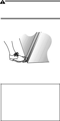
This procedure should only be used when pressure remains in the sterilizer chamber, and the door cannot be opened normally because the sterilizer has lost either electrical or water utilities. This emergency door opening procedure can be used to retrieve a load in the chamber. This procedure requires pushing on the door cover to retract the door seal into the groove, then pushing the door downward manually.
Procedure:
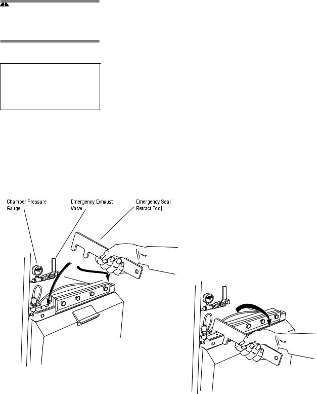
1.Swing open the access panel of the sterilizer. Open the emergency exhaust hand valve until chamber exhausts to 0.0 psig. See Figure 3-11.
2.Using the door release tool provided, press on the upper left hand and right hand corners of the chamber door (see Fig. 3-11). The door should give inward slightly, indicating that the seal has been pushed into the groove. The door must “bottom out” against the metal end-frame of the sterilizer chamber.
3.Close the access panel of the sterilizer.
4.Press down on the door handle to lower the door. The door will slide stiffly, so be prepared to press down hard.
5.Once the door is open, do not use the sterilizer until the unit has been examined by a qualified service technician. Further use without attention may damage the sterilizer.
6.Close the emergency exhaust valve.
Figure 3-11. Emergency Door Opening Procedure
3-10
129367-408 |
Operating Instructions |
Component Identification |

3.11 Optional
Electric Steam
Generator
CAUTION – POSSIBLE EQUIPMENT DAMAGE: Failure to flush generator on a daily basis could result in generator malfunction.
Pressing STOP TIMER stops flush phase and resets timer to three minutes.
Pressing CANCEL bypasses flush phase and advances display to screen #1. Do not press CANCEL unless generator has already been flushed that day.
 WARNING – BURN HAZARD:Beforedailyflushing of the generator, generator must be at zero psig and cooled to room temperature.
 CAUTION – POSSIBLE EQUIPMENT DAMAGE: Beforeflushinggenerator, ensure generator drain valve is fully open.
If a building steam source is not available, the sterilizer may be equipped with an electric steam generator. The generator automatically converts water to steam using electric heat. The steam created is then used to power the sterilizer.
Steam generators are highly susceptible to mineral scaling if the supplied water has any level of hardness. Refer to Table 3-1 for water quality requirements.
IMPORTANT: Regardless of the hardness level of supplied water, the generator must be flushed every day before use to prevent mineral scaling or carryover of debris into the chamber.
ATTENTION: Warranty on this steam generator will be voided unless daily flushing procedures are performed.
Daily Generator Start Up Procedure
1.Press the ON button on the sterilizer touch screen (screen #0). Display advances to screen #72. Instructions on how to flush the generator are listed on screen #72.
72
FLUSH GENERATOR
THE GENERATOR SHOULD BE FLUSHED
EVERY DAY.
TO FLUSH GENERATOR:
1.VERIFY GENERATOR PRESSURE IS 0 psig.
2.OPEN GENERATOR MANUAL DRAIN VALVE.
3.PRESS START TIMER TO BEGIN FLUSH PHASE.
4.ALLOW GENERATOR TO FLUSH FOR 5 MINUTES.
FLUSH TIMER: 5:00
START |
STOP |
CANCEL |
|
TIMER |
TIMER |
||
|
2.Check generator pressure gauge (see Fig. 3-12). Generator must be at 0.0 psig and room temperature before flushing.
Water Supply Valve to |
|
the Generator |
Generator Pressure Gauge |
Water-level |
Sight Glass |
Generator Electric Box
Generator Drain Valve
Figure 3-12. Optional Steam Generator
3-11
Component Identification |
Operating Instructions |
129367-408 |

 WARNING – BURNHAZARD: Sterilizeroperatormaybeseverelyburnedbyscaldingwater if the water level control malfunctions.Thesteamgenerator level control may malfunction if the supply water exceeds 26,00 ohms/cm (38.5 micromhos conductivity min.). Do not connect to treated water (e.g., distilled, reverse osmosis, deionized) unless water resistivity is determined to be acceptable. If water exceeds 26,000 ohms/ cm,contactSTERISforinformationconcerningmodifications required to the generator control system.
3-12
NOTE: If generator is not at 0.0 psi, the Flush can be bypassed by pressing CANCEL, however the flush should not be bypassed on a continuous basis or else damage to the generator may occur. Failure to flush the generator on a daily basis will void the generator warranty.
To ensure generator is at 0.0 psig the sterilizer can be shut off at end of the day and by next morning the unit will be able to be flushed. Approximately seven hours are required for generator to cool down to less than 140°F.
3.Open drain valve on the side of the generator electric box (see Fig. 3-12).
4.Verify that the water supply valve to the sterilizer is open.
5.Ensure the water supply valve to the generator is open (see Fig. 3-12).
6.Press START TIMER on screen #72. Water automatically flushes through the generator and out the drain for 3.0 minutes. Flush timer on screen #72 counts down time remaining in the flush phase.
7.After 5.0 minutes, alarm buzzer sounds and display advances to screen #73. Instructions on how to restart the generator are listed on screen #73.
73
FLUSHING OF GENERATOR COMPLETE
TO RESTART GENERATOR:
1.CLOSE GENERATOR MANUAL DRAIN VALVE.
2.PRESS CONTINUE TO START THE GENERATOR AND ADVANCE TO THE MAIN MENU.
CONTINUE
8.Close the generator drain valve.
9.PressCONTINUE onscreen#73.Generatorautomaticallyfillstotheproper level and starts to heat. Display screen advances to the Main Menu screen (#1). Allow ten minutes warm-up time once generator starts to fill.
10. Close front cabinet panel.
NOTE: The generator must be flushed every day before use.
Table 3-1. Required Feed Water Quality for
Carbon Steel Steam Generators
|
Nominal |
Maximum |
|
Condition |
Conditions |
Conditions |
|
|
|
|
|
Temperature |
as supplied |
140° F (60° C) |
|
|
|
|
|
Total Hardness as CaCO3* |
0-17 mg/L |
130 mg/L |
|
Total Dissolved Solids |
50-150 |
mg/L |
250 mg/L |
|
|
|
|
Total Alkalinity as CaCO3 |
50-100 |
mg/L |
180 mg/L |
pH |
6.8-7.5 |
6.5-8.5 |
|
|
|
|
|
Total Silica |
0.1-1.0 |
mg/L |
2.5 mg/L |
|
|
|
|
Resistivity - ohms/cm |
2000-6000 |
26000 |
|
|
|
|
|
*17.1 mg/L = 1 grain hardness
129367-408 |
Operating Instructions |
Component Identification |

STERILIZER OPERATION |
4 |
4.1 Before
Operating the
Sterilizer
 WARNING – BURN HAZARD: Sterilizer, rack/ shelves, and loading car will be hot after cycle is run. Always wear protective gloves and apron when removing a processed load. Protective gloves and apron must be worn when reloading sterilizer following the previous operation.
 WARNING – SLIPPING HAZARD: To prevent falls keep floors dry by immediately wiping up any spilled liquids or condensation in sterilizer loading or unloading area.
Sterilizer Operation
Operate sterilizer by referring to the appropriate cycle description in this section. The steps described on the next three pages are general instructions that apply to all cycle operations.
1.Press ON touch screen pad on the sterilizer control display.
• The printer records the time and date that the power is turned ON.
2.Open chamber door
a.Check that drain strainer is clean and in place and that chamber interior is clean. See ROUTINE MAINTENANCE MANUAL
(P129367-410) if cleaning is necessary.
b.Close chamber door.
3.Open access door on the operating end of the sterilizer — refer to Figure 4-1. Turn on steam (Fig. 4-1a) and water (Fig. 4-1b) supplies. Close access door.
• Steam enters jacket and begins to warm chamber.
4.Open control access door.
|
|
Control |
|
Access |
Access |
Open |
Panel |
Door |
|
Steam |
|
Closed |
Supply |
|
Valve |
|
|
|
(4-1a) |
|
|
JACKET |
|
CHAMBER |
|
|
4-1a Steam Supply Valve
Open
Closed
4-1b Water Supply Valve
Figure 4-1. Steam Valves
Operating Instructions
Water Supply Valve (4-1b)
4-1
129367-408
Loading...