


 Loading...
MAINTENANCE MANUAL
Harmony LA™ Surgical Lighting and Visualization
System
(06/22/05) |
P764330-226 |

A Word From STERIS Corporation
ADVISORY
The operation and maintenance procedures recommended by STERIS→ are described in this manual. Only these recommended maintenance procedures should be followed.
A listing of the safety precautions to be observed when operating and servicing this equipment can be found in Section 1 of this manual. Do not operate or service this equipment until you have become familiar with this information.
Any alteration of this equipment not authorized or performed by STERIS Engineering Service which could affect its operation will void the warranty, could adversely affect sterilization efficacy, could violate federal, state, and local regulations, and could jeopardize your insurance coverage.
© 2005, STERIS Corporation All rights reserved.
INDICATIONS FOR USE
The HarmonyTM LA Surgical Lighting and Visualization System is a variable pattern, variable intensity surgical lighting fixture designed to provide visible illumination of the surgical field or the patient for the operating room staff.
Printed in U.S.A.
i
764330-226

Table of Contents
Section Title Page
Section 1: Listing of Safety Precautions.......................................................................... |
1-1 |
|
1.1 |
Definition of Symbols .................................................................................................................................. |
1-4 |
Section 2: General Information .......................................................................................... |
2-1 |
|
2.1 |
General Description ..................................................................................................................................... |
2-1 |
2.2 |
Harmony LA 300/500/700 Lighthead Optical Performance ........................................................................... |
2-1 |
2.3 |
Special Consumables ................................................................................................................................. |
2-2 |
Section 3: Operating Instructions..................................................................................... |
3-1 |
|
3.1 |
General Instructions .................................................................................................................................... |
3-1 |
|
3.1.1 To Adjust Lighthead Intensity Levels: ................................................................................................ |
3-1 |
|
3.1.2 Control Center ................................................................................................................................... |
3-1 |
|
3.1.3 Surgeon’s Control Buttons ................................................................................................................. |
3-2 |
3.2 |
Harmony LA 500 Lighthead Lamp Failure Indications .................................................................................. |
3-2 |
3.3 |
Harmony LA 500 Lighthead Positioning ....................................................................................................... |
3-3 |
3.4 |
Harmony LA 500 Lighthead Pattern Adjustment .......................................................................................... |
3-4 |
3.5 |
Lighthandle and Lighthandle Cover .............................................................................................................. |
3-4 |
|
3.5.1 Installing and Using Lighthandle and Lighthandle Cover ................................................................... |
3-4 |
|
3.5.2 Metal Sterilizable Handle ................................................................................................................. |
3-6 |
3.6 |
Harmony LA Monitor Arms .......................................................................................................................... |
3-7 |
3.7 |
Install Flat Panel Monitor Yoke Handle Disposable Sterile Covers ............................................................... |
3-8 |
3.8 |
Video Camera Installation or Removal ......................................................................................................... |
3-9 |
|
3.8.1 Installation ....................................................................................................................................... |
3-9 |
|
3.8.2 Removal .......................................................................................................................................... |
3-9 |
3.9 |
Lighthead Positioning with Video Camera .................................................................................................... |
3-9 |
3.10 Video Camera Operation .......................................................................................................................... |
3-10 |
|
|
3.10.1 HERMES-Ready Control Center .................................................................................................. |
3-10 |
|
3.10.2 Optional Foot Control ................................................................................................................... |
3-10 |
3.11 Guidelines for Maximizing Video Image ................................................................................................... |
3-11 |
|
|
3.11.1 Engage Manual Focus ................................................................................................................. |
3-11 |
3.12 DeepSite control center status indicators ................................................................................................ |
3-12 |
|
|
3.12.1 Intensity Level Status ................................................................................................................... |
3-12 |
|
3.12.2 Lamp Life Status .......................................................................................................................... |
3-12 |
Section 4: Service Mode .................................................................................................... |
4-1 |
|
4.1 |
Service mode procedure ............................................................................................................................. |
4-1 |
4.2 |
Service Menu 1 Screen ............................................................................................................................... |
4-1 |
4.3 |
Service Menu 2 Screen ............................................................................................................................... |
4-2 |
4.4 |
Service Menu 3 Screen ............................................................................................................................... |
4-3 |
Section 5: Theory of Operation ......................................................................................... |
5-1 |
|
5.1 |
Suspension System .................................................................................................................................... |
5-1 |
5.2 |
Major System Components ......................................................................................................................... |
5-1 |
|
5.2.1 Harmony LA 500 LightHead ............................................................................................................. |
5-1 |
|
5.2.2 Harmony LA 300 Lighthead .............................................................................................................. |
5-1 |
|
5.2.3 Harmony LA 700 Lighthead .............................................................................................................. |
5-1 |
|
5.2.4 Flat Panel Monitor Arm .................................................................................................................... |
5-1 |
|
5.2.5 CRT Monitor Arm ............................................................................................................................. |
5-1 |
|
5.2.6 DeepSite Arm .................................................................................................................................. |
5-2 |
|
5.2.7 Ambient Light .................................................................................................................................. |
5-2 |
iii
764330-226

Section Title Page
Section 5: Theory of Operation (continued)
5.3 |
Control System ........................................................................................................................................... |
5-2 |
5.4 |
Lamp Power Explanation ............................................................................................................................. |
5-2 |
5.5 |
Lamp Startup Explanation ........................................................................................................................... |
5-2 |
5.6 |
Lighthead BTU Output ................................................................................................................................. |
5-3 |
5.7 |
Serial Number Explanation .......................................................................................................................... |
5-3 |
5.8 |
Harmony LA Worldwide Release Control System Theory of Operation ......................................................... |
5-3 |
Section 6: Inspection and Maintenance............................................................................ |
6-1 |
|
6.1 |
General ....................................................................................................................................................... |
6-1 |
6.2 |
Cleaning the Equipment .............................................................................................................................. |
6-1 |
|
6.2.1 Cleaning Implements ........................................................................................................................ |
6-3 |
|
6.2.2 Areas To Be Cleaned ......................................................................................................................... |
6-3 |
|
6.2.3 General Cleaning/Disinfecting Procedure .......................................................................................... |
6-3 |
|
6.2.4 Cleaning the Lens ............................................................................................................................. |
6-3 |
|
6.2.5 Recommended Sterilization Techniques for the Metal Sterile Handle ................................................. |
6-3 |
|
6.2.6 Cleaning Hand-held Control ............................................................................................................... |
6-4 |
6.3 |
Lamp Replacement ..................................................................................................................................... |
6-4 |
|
6.3.1 Replace Harmony LA 500 and LA 700 Lamps .................................................................................. |
6-4 |
|
6.3.2 Reset Harmony LA 700 Lampholder ................................................................................................ |
6-7 |
|
6.6.1 Reset Harmony LA 700 Lampholder ................................................................................................ |
6-7 |
6.4 |
Routine Inspection ...................................................................................................................................... |
6-8 |
6.5 |
Preventive Maintenance Guide ................................................................................................................... |
6-8 |
6.6 |
Troubleshooting ........................................................................................................................................... |
6-8 |
Section 7: Field Test Procedure ......................................................................................... |
7-1 |
|
7.1 |
General ....................................................................................................................................................... |
7-1 |
|
7.1.1 Special Tools Required ...................................................................................................................... |
7-1 |
7.2 |
Scope ......................................................................................................................................................... |
7-2 |
7.3 |
General Test ................................................................................................................................................ |
7-2 |
7.4 |
Mechanical Test .......................................................................................................................................... |
7-2 |
7.5 |
Optical Test (Harmony LA 500 & 700) .......................................................................................................... |
7-2 |
7.6 |
Suspension System Field Test Procedure ................................................................................................... |
7-3 |
7.7 |
Wall Control Field Test Procedure ................................................................................................................ |
7-4 |
Section 8: Component Repair and Replacement............................................................. |
8-1 |
|
8.1 |
Brake Adjustment (all locations) .................................................................................................................. |
8-1 |
8.2 |
Light or monitor Spring Arm Spring Tension Adjustment .............................................................................. |
8-2 |
|
8.2.1 Light Spring Arm .............................................................................................................................. |
8-2 |
|
8.2.2 Monitor Spring Arm .......................................................................................................................... |
8-2 |
8.3 |
Commutator Troubleshooting ....................................................................................................................... |
8-2 |
8.4 |
Knuckle Cover Removal (Any) and Assembly ............................................................................................. |
8-3 |
8.5 |
De-install harmony LA 500 Lighthead from the Suspension Arm ................................................................. |
8-3 |
|
8.5.1 Before Installing Monitor Spring Arm ................................................................................................ |
8-4 |
8.6 |
Removal of the Control Center Front Panel .................................................................................................. |
8-5 |
8.7 |
Control Center Precautions ......................................................................................................................... |
8-6 |
8.8 |
Commutator Replacement (Main Suspension, not spring arm) .................................................................... |
8-7 |
8.9 |
Voltage Adjustment on Power Supply ......................................................................................................... |
8-8 |
8.10 Electrical Connector Repair (Suspension System) .................................................................................... |
8-8 |
|
8.11 Using Test Harness to Isolate Wiring Faults ............................................................................................... |
8-8 |
|
iv
764330-226

Section Title Page
Section 8: Component Repair and Replacement (continued)
8.12 |
Lens Clip Replacement Procedures ........................................................................................................... |
8-9 |
8.13 |
Use of Brake Ring Centering Tool for Harmony LA Lights ........................................................................ |
8-12 |
8.14 |
Installation Instructions for Harmony LA Wedge Lock Shim Kit ............................................................... |
8-13 |
|
8.14.1 Choosing Appropriate Shim ......................................................................................................... |
8-13 |
8.15 |
Discoloration of Lightheads ..................................................................................................................... |
8-14 |
8.16 |
Using Jumper Wires ................................................................................................................................ |
8-14 |
|
8.16.1 Using Jumper Wires 755717-334 .................................................................................................. |
8-14 |
|
8.16.2 Using Jumper Wires 755717-352 and 755717-353 ........................................................................ |
8-14 |
|
8.16.3 Using Jumper Wire 755717-302 For Troubleshooting Harmony LA Camera System ...................... |
8-15 |
Section 9: Illsutrated Parts Breakdown ............................................................................ |
9-1 |
|
v
764330-226

List of Illustrations
Description Page Number
Section 3: Operating Instructions
Figure 3-1. Harmony Control Center Main Menu ................................................................................................ |
3-1 |
|
Figure 3-2. Lighthead Surgeon’s Control Buttons (Harmony LA 500 Lighthead with Standard Handle Shown) .... |
3-2 |
|
Figure 3-3. Lamp Status LED ............................................................................................................................ |
3-2 |
|
Figure 3-4. Suspension Positioning ................................................................................................................... |
3-3 |
|
Figure 3-5. |
Light Pattern Adjustment ................................................................................................................. |
3-4 |
Figure 3-6. Standard Lighthandle ....................................................................................................................... |
3-5 |
|
Figure 3-7. Harmony Monitor Configurations ...................................................................................................... |
3-7 |
|
Figure 3-8. |
Installing Disposable Sterile Monitor Handle Covers ........................................................................ |
3-8 |
Figure 3-9. |
Optional Camera Installation ........................................................................................................... |
3-9 |
Figure 3-10. Install Camera Disposable Sterile Cover ........................................................................................ |
3-9 |
|
Figure 3-11. Optional Camera Controllers ........................................................................................................ |
3-11 |
|
Figure 3-12. DeepSite Control Center Indicators .............................................................................................. |
3-12 |
|
Section 4: Service Mode
Figure 4-1. Service Menu 1 Screen .................................................................................................................... |
4-1 |
Figure 4-2. Service Menu 2 Screen .................................................................................................................... |
4-2 |
Figure 4-3. Service Menu 3 Screen .................................................................................................................... |
4-3 |
Section 5: Theory of Operation
Figure 5-1. View of Global Control Power Status Boards ................................................................................... |
5-4 |
Figure 5-2. Wedge Lock and Vertical Tube ......................................................................................................... |
5-6 |
Figure 5-3. Typical Harmony LA System ........................................................................................................... |
5-7 |
Figure 5-4. Domestic Medium/Large Lighthead Board Controller ........................................................................ |
5-7 |
Figure 5-5. Domestic Harmony System Block Diagram ..................................................................................... |
5-8 |
Figure 5-6. Domestic Deepsite Illuminator Box .................................................................................................. |
5-8 |
Figure 5-7. Domestic Master Control Board w/DeepSite Interface Board & Analog Video Interface Board ......... |
5-9 |
Figure 5-8. Domestic LCD Interface Board w/Membrane Switch Panel, Service Port AUX Port, |
|
IR Receiver, & Foot Control Assembly ........................................................................................... |
5-10 |
Figure 5-9. Domestic Power Supply & Power Status Module ........................................................................... |
5-11 |
Figure 5-10. Domestic Remote Power Module ................................................................................................. |
5-12 |
Figure 5-11. Domestic Hub Interface Board ..................................................................................................... |
5-13 |
Figure 5-12. Domestic Hub Power Circuit ........................................................................................................ |
5-13 |
Figure 5-13. Domestic Schematic ................................................................................................................... |
5-14 |
Figure 5-14. Domestic Small Lighthead Controller Board ................................................................................. |
5-15 |
Figure 5-15. Domestic Lighthead Camera Module ............................................................................................ |
5-15 |
Figure 5-16. Domestic Video & Power Kits ...................................................................................................... |
5-16 |
Figure 5-17. Global Medium/Large Lighthead Board Controller ......................................................................... |
5-17 |
Figure 5-18. Global Harmony System Block Diagram ...................................................................................... |
5-17 |
Figure 5-19. Global Deepsite Illuminator Box ................................................................................................... |
5-18 |
Figure 5-20. Global Master Control Board w/DeepSite Interface Board & Analog Video Interface Board .......... |
5-18 |
Figure 5-21. Global LCD Interface Board w/Membrane Switch Panel, Service Port AUX Port, |
|
IR Receiver, & Foot Control Assembly ........................................................................................... |
5-19 |
Figure 5-22. Global Power Supply & Power Status Module .............................................................................. |
5-20 |
Figure 5-23. Global Remote Power Module ...................................................................................................... |
5-21 |
vi
764330-226

List of Illustrations (Continued)
Description Page Number
Section 5: Theory of Operation (Continued)
Figure 5-24. Global Hub Interface Board .......................................................................................................... |
5-21 |
|
Figure 5-25. |
Global Hub Power Circuit ............................................................................................................. |
5-22 |
Figure 5-26. |
Global Schematic ........................................................................................................................ |
5-23 |
Figure 5-26. |
Global Small Lighthead Controller Board ...................................................................................... |
5-23 |
Figure 5-27. Global Lighthead Camera Module ................................................................................................ |
5-23 |
|
Figure 5-28. Global Power & Video Kits ........................................................................................................... |
5-24 |
|
Section 6: Inspection and Maintenance
Figure 6-1. |
Areas To Be Cleaned ....................................................................................................................... |
6-2 |
Figure 6-2. |
Lamp Status LED ............................................................................................................................ |
6-4 |
Figure 6-3. |
Lamp Replacement Procedure (Harmony LA 500 Lighthead Shown) ................................................ |
6-6 |
Figure 6-4. |
Reset Harmony LA 700 Lampholder Lamp Position ......................................................................... |
6-7 |
Section 7: Field Test Procedure
Figure 7-1. |
Inspect Wire Routing........................................................................................................................ |
7-2 |
Figure 7-2. |
Place Light Meter on Table ............................................................................................................... |
7-2 |
Figure 7-3. |
Check Secondary Spindle Stops ..................................................................................................... |
7-3 |
Figure 7-4. Check Safety Ring and Safety Ring Pins ........................................................................................ |
7-4 |
|
Figure 7-5. |
Check Hub Insterface Board Mounting and Connections ................................................................. |
7-4 |
Section 8: Component Repair and Replacement
Figure 8-1. |
Adjust Lighthead/Yoke Brake Tension .............................................................................................. |
8-1 |
Figure 8-2. Adjust Support Arm/Spring Arm Brake Tension ................................................................................ |
8-1 |
|
Figure 8-3. Adjust Spring Arm/Yoke Brake Tension ............................................................................................ |
8-1 |
|
Figure 8-4. Adjust Upper Support Arm Brake Tension ........................................................................................ |
8-1 |
|
Figure 8-5. Remove Cover to Access Spring Arm Tension Adjustment .............................................................. |
8-2 |
|
Figure 8-6. |
Adjust Spring Arm Tension ............................................................................................................... |
8-2 |
Figure 8-7. Monitor Spring Arm Tension Adjustment Access ............................................................................. |
8-2 |
|
Figure 8-8. |
Harmony Wall Control ON/OFF Switch ............................................................................................. |
8-3 |
Figure 8-9. |
Push Spring Arm and Lighthead Toward Floor .................................................................................. |
8-3 |
Figure 8-10. Safety Screw Locations ................................................................................................................. |
8-4 |
|
Figure 8-11. Remove Lighthead ......................................................................................................................... |
8-4 |
|
Figure 8-12. Gently Pull Wires from Lighthead. .................................................................................................. |
8-5 |
|
Figure 8-13. Ensure Connections Are Secure .................................................................................................... |
8-5 |
|
Figure 8-14. Fold Wiring into Loop ..................................................................................................................... |
8-5 |
|
Figure 8-15. Tuck Looped Wires intoYoke Tube .................................................................................................. |
8-5 |
|
Figure 8-16. Ensure Looped Wires are Dressed Away from any Moving Parts. ................................................ 8-5
Figure 8-17. Monitor Spring Arm Safety Pin Location ........................................................................................ |
8-5 |
|
Figure 8-18. Loosen Screws at Top of Control Center Cover .............................................................................. |
8-5 |
|
Figure 8-18. Remove Control Center Bottom Screws ......................................................................................... |
8-6 |
|
Figure 8-19. Commutator Componenets Arragned for Assembly ........................................................................ |
8-7 |
|
Figure 8-20. Commutator ................................................................................................................................... |
8-8 |
|
Figure 8-21. Voltage Adjustment Screw ............................................................................................................. |
8-8 |
|
Figure 8-22. |
Wiring Fault Test Harness .............................................................................................................. |
8-8 |
Figure 8-23. |
Check Clips ................................................................................................................................... |
8-9 |
Figure 8-24. |
Check Lens Clips For Clearance .................................................................................................... |
8-9 |
Figure 8-25. |
Lens Clip Clearance Detail View .................................................................................................... |
8-9 |
vii
764330-226

List of Illustrations (Continued)
Description Page Number
Section 8: Component Repair and Replacement (Continued)
Figure 8-26. Recenter Reflector ....................................................................................................................... |
8-10 |
|
Figure 8-27. Reposition Lens Assembly Using Lighthandle .............................................................................. |
8-10 |
|
Figure 8-28. Rotate Lighthandle to Check for Binding ...................................................................................... |
8-10 |
|
Figure 8-29. Lens Clips to Be Removed ......................................................................................................... |
8-10 |
|
Figure 8-30. Check Lens Clip Alignment .......................................................................................................... |
8-11 |
|
Figure 8-31. Insert Allen Wrenches into Lens Clips ......................................................................................... |
8-11 |
|
Figure 8-32. Lift Lens Using Spare Lens Clip ................................................................................................... |
8-11 |
|
Figure 8-33. Insert Spare Lens Clip ................................................................................................................. |
8-11 |
|
Figure 8-34. |
Remove Lens Clip ....................................................................................................................... |
8-11 |
Figure 8-35. |
Remove Allen Wrench ................................................................................................................. |
8-12 |
Figure 8-36. |
Lide in New Lens Clip .................................................................................................................. |
8-12 |
Figure 8-37. |
Wedge Lock Details ..................................................................................................................... |
8-13 |
Section 9: Illustrated Parts Breakdown
Figure 9-1A. Harmony LA Surgical Light And Visualization Assembly, Complete ............................................... |
9-4 |
Figure 9-1B. Harmony LA Surgical Light And Visualization System Covers ....................................................... |
9-6 |
Figure 9-2. Harmony LA Ceiling Plate Assembly ............................................................................................... |
9-8 |
Figure 9-3A. Harmony LA Extension Arms - Dual Spindle ............................................................................... |
9-11 |
Figure 9-3B. Harmony LA Extension Arms - Triple Spindle .............................................................................. |
9-12 |
Figure 9-3C. Harmony LA Extension Arms - Triple Spindle With Spacer ........................................................... |
9-13 |
Figure 9-3D. Harmony LA Extension Arms - Dual Spindle With Spacer ............................................................ |
9-14 |
Figure 9-4. Harmony LA Extension Arm For Flat Panel Or CRT Monitor .......................................................... |
9-16 |
Figure 9-5A. Harmony LA Yoke - For Flat Panel Monitor .................................................................................. |
9-18 |
Figure 9-5B. Harmony LA Yoke - For CRT Monitor ........................................................................................... |
9-20 |
Figure 9-6. Harmony LA Spring Arms For FPM And CRT ................................................................................ |
9-22 |
Figure 9-7. Harmony LA Spring Arm/Yoke - For Medium Lighthead.................................................................. |
9-24 |
Figure 9-8A. Harmony LA 500 Lighthead ......................................................................................................... |
9-26 |
Figure 9-8B. Harmony LA 700 Lighthead ......................................................................................................... |
9-28 |
Figure 9-8C. Harmony LA Optical Hub ............................................................................................................. |
9-30 |
Figure 9-9A. Harmony LA Wall Control Assembly ............................................................................................ |
9-33 |
Figure 9-9B. Harmony LA Wall Control Assembly - Cables (Table) ................................................................... |
9-34 |
Figure 9-9C. Harmony LA Wall Control Panel Assembly .................................................................................. |
9-36 |
Figure 9-9D. Harmony LA Wall Control Panel Assembly (Global) ...................................................................... |
9-38 |
Figure 9-9E. Harmony LA Master Controller Assembly .................................................................................... |
9-40 |
Figure 9-9F. Harmony LA LCD Display Assembly ............................................................................................ |
9-42 |
Figure 9-10. Remote Power Module Assembly ................................................................................................ |
9-44 |
Figure 9-11. Remote Power Module - Panel Assembly ..................................................................................... |
9-46 |
Figure 9-12. Remote Power Module Assembly with Auto Change Over (Global) .............................................. |
9-48 |
Figure 9-13. Remote Power Module Back-Up Power Status Assembly Panel (Global) ..................................... |
9-50 |
Figure 9-14. Low Profile Control Assembly ...................................................................................................... |
9-52 |
Figure 9-15. Panel & Component Assembly (Low Profile) ................................................................................ |
9-54 |
Figure 9-16. Harmony LA 500 Mobile Stand Assembly .................................................................................... |
9-56 |
Figure 9-17. Mobile Stand Base Assembly ...................................................................................................... |
9-58 |
Figure 9-18A. Custom Cable Kits (Table) ......................................................................................................... |
9-60 |
Figure 9-18B. Custom Cable Kits (Table) ......................................................................................................... |
9-60 |
Figure 9-18C. Custom Cable Kits (Table) ......................................................................................................... |
9-61 |
viii
764330-226
List of Tables |
|
|
|
|
|
Description |
Page Number |
Section 2: General Information |
|
Table 2-1. Lighthead Performance Data ............................................................................................................. |
2-1 |
Table 2-1. Special Consumables ........................................................................................................................ |
2-2 |
Section 4: Service Mode |
|
Table 4-1. Default Control Center Settings ......................................................................................................... |
4-3 |
Section 5:Theory Of Operation |
|
Table 5-1. Lighthead: Large Socket: Primary and Secondary ........................................................................... |
5-2 |
Table 5-2. Lighthead: Medium Socket: Primary ................................................................................................ |
5-2 |
Table 5-3. Lighthead: Medium Socket: Secondary ........................................................................................... |
5-3 |
Table 5-4. Lighthead: Small Socket: Primary ................................................................................................... |
5-3 |
Section 6: Inspection and Mainenance |
|
Table 6-1. Troubleshooting Guide ....................................................................................................................... |
6-9 |
Table 6-2. Harmony Lighting and Visualization System Preventive Maintenance Guide ................................... |
6-18 |
ix
764330-226

Section 1: Listing of Safety Precautions
The following Safety Precautions must be observed when operating or servicing this surgical lighting system. WARNING indicates the potential for personal injury and CAUTION indicates the potential for damage to equipment. For emphasis, certain Safety Precautions are repeated throughout the manual. It is important to review ALL Safety Precautions before operating or servicing the unit.
Strictly following these Safety Precautions enhances your ability to safely and effectively utilize the unit and helps the customer avoid improper maintenance methods which may damage the unit or render it unsafe. It is important to understand that these Safety Precautions are not exhaustive; customers are encouraged to develop their own safety policies and procedures to enhance and compliment these Safety Precautions.
WARNING – ELECTRIC SHOCK AND BURN HAZARD:
Disconnect all utilities to lighting fixture before servicing. Do not install the lighting fixture unless all utilities have been properly locked out. Always follow OSHA Lockout-Tagout and electrical safety-related work practice standards. (See 29 CFR 1910.147 and .331 through .335.)
Do not remove covers or perform service other than as described in this equipment manual. Refer servicing to qualified service personnel. (Maintenance Manual P764330-226.)
WARNING – EXPLOSION HAZARD:
Do not use lighting fixture in the presence of flammable anesthetics.
WARNING – PINCH AND CRUSH HAZARD:
Do not pinch fingers between the structural plate and the vertical tube as the assembly is lifted.
The safety ring must be installed.
Pinch points are created during extreme articulation of the suspension system. Do not place hands on or near the suspension knuckle during lighthead articulations.
WARNING – IMPACT HAZARD:
Do not remove tension screw from the spring arm joint until the lighthead has been securely installed onto the spring arm. Note: This warning applies at both installation and de-installation procedures.
WARNING – PERSONAL INJURY HAZARD:
Do not attempt to replace the lamp unless power is turned off and the lighthead has cooled sufficiently.
Do not attempt to clean lighthead unless power is turned off and the lighthead has cooled sufficiently.
Do not remove monitor-arm safety pin until monitor is installed.
Monitor extension arm must have monitor (or equivalent counterweight) installed to keep arm in required positions while installing sliding guards.
Avoid looking directly at high-intensity light, whether at the lamp or directly at the lighthead. Eye injury may result.
1-1
764330-226
WARNING – POSSIBLE PATIENT INJURY HAZARD:
Failure to engage the lighthandle cover completely may result in cover falling from lighthead during the procedure.
WARNING – BIOHAZARD:
Sterile disposables are intended for single use only.
Universal precautions must be observed when disposing of any single use disposable item.
WARNING – DISPOSAL HAZARD:
This product contains materials which may require disposal through appropriately licensed and permitted hazardous waste management firms.
CAUTION – POSSIBLE EQUIPMENT DAMAGE:
Use of any disinfectant solution OTHER than those listed below may cause discoloration or deformation on the polycarbonate lens surface: Coverage® Spray HBV, Coverage® HBV Concentrate, T.B.Q.®, or Coverage Plus®, CoverageTM Spray Disinfectant Cleaner, or Germicidal Cloth. Cleaning solutions other than those listed have NOT been tested for compatibility or effectiveness. Always follow manufacturer instructions for concentrations and use of cleaning products.
Use only recommended cleaning/disinfecting and/or anti-static agents on this light. Some degree of staining, pitting, and/or discoloration could occur if a phenolic-, iodophor-, or glutaraldehyde-based disinfectant is used on the surfaces of this light. Also, use of alcohol or aerosol spray cleaner/disinfectants (e.g., Lysol®) containing a substantial amount of alcohol in the formula can damage the polycarbonate lens.
Prevent leakage of fluids into interior of lighthead.
Avoid discoloration of control center keypad and display. Do not clean control center with Betadine® solutions or allow such solutions to contact keypad and display surfaces.
Do not scratch optical coating on accessible portions of optic assembly when cleaning; always wear rubber gloves and use only a clean, white, lint-free cloth when wiping internal surfaces.
Appropriate components of this lighting system have been tested and found in compliance with IEC 60601- 1-2 (1st Edition 1993-04), Medical Electrical Equipment – Part 1: General Requirements for Safety; Electromagnetic Compatibility (EMC). There is, however, a potential for electromagnetic or other interference between this equipment and other devices. Should you experience interference, relocate this device or minimize the use of the affected equipment while this device is in operation.
Do not touch the glass portion of the lamp with bare fingers. Skin oils can cause deterioration of material leading to possible failure of the lamp.
Accurate measurement and calculation in finding the point where the first hole is drilled for the safety ring is of critical importance in correctly installing the vertical tube. Check all measurements and calculations twice before drilling the first hole.
Do not pinch wires that exit the vertical tube as the assembly is lifted. Gently route wires from the vertical tube out of the way as the suspension system is lifted into place.
1-2
764330-226

CAUTION – POSSIBLE EQUIPMENT DAMAGE (Continued):
Do not pinch wire on the ceiling structure or vertical tube.
During all mounting steps, ensure wires are not pinched between mechanical components of suspension, spring arms, or lightheads.
Harness connectors must be slipped into expandable sheathe before routing through monitor yoke.
•Failure to use sheath may cause connector damage during routing.
•Slip sheathe only far enough onto the harness to protect connector bundle. If sheathe is slipped too far onto the harness, removing it after routing may be difficult.
Do not touch glass portion of lamp with bare fingers. Skin oils can cause deterioration of material leading to possible failure of the lamp.
Sliding guards may be damaged if not installed properly into internal grooves.
On early light systems, the wire clamp must be loosened to allow the wiring within the vertical tube to be free.
1-3
764330-226

1.1 DEFINITION OF |
Symbol |
Definition |
||||||||||
SYMBOLS |
||||||||||||
|
|
|
|
|
|
|
|
|
|
|
|
|
|
|
|
|
|
|
|
|
|
|
|
|
ON |
|
|
|
|
|
|
|
|
|
|
|
|
|
|
|
|
|
|
|
|
|
|
|
|
|
STANDBY |
|
|
|
|
|
|
|
|
|
|
|
|
|
|
|
|
|
|
|
|
|
|
|
|
|
Lamp Out |
|
|
|
|
|
|
|
|
|
|
|
|
|
|
|
|
|
|
|
|
|
|
|
|
|
Protective Earth (Ground) |
|
|
|
|
|
|
|
|
|
|
|
|
|
|
|
|
|
|
|
|
|
|
|
|
|
|
|
|
|
|
|
|
|
|
|
|
|
|
|
|
|
|
|
|
|
|
|
|
|
|
|
|
|
|
|
|
|
|
|
|
|
|
|
|
Attention, consult manual for further instructions |
|
|
|
|
|
|
|
|
|
|
|
|
|
|
|
|
|
|
|
|
|
|
|
|
|
|
|
|
|
|
|
|
|
|
|
|
|
|
|
|
|
|
|
|
|
|
|
|
|
|
|
Hot |
|
|
|
|
|
|
|
|
|
|
|
||
|
SER. NO. |
Serial Number of Unit |
||||||||||
|
|
|
|
|
|
|
|
|
|
|
|
|
|
|
|
V~ |
Voltage Rating of Unit, Alternating Current |
||||||||
|
|
|
|
|
|
|
|
|
|
|
|
|
|
|
|
|
A |
Amperage Rating of Unit |
|||||||
|
|
|
|
|
|
|
|
|
|
|
|
|
|
|
|
Hz |
Frequency Rating of Unit |
||||||||
|
|
|
|
|
|
|
|
|
|
|
|
|
|
+ |
|
|
|
|
|
Increase Intensity (Surgeon's Control Buttons) |
|||||
|
|
|
|
|
|
|
|
|
|
|
|
|
|
- |
|
|
|
|
|
Decrease Intensity (Surgeon's Control Buttons) |
|||||
|
|
|
|
|
|
|
|
|
|
|
|
|
|
|
|
|
|
|
|
|
|
|
|
|
Zoom |
|
|
|
|
|
|
|
|
|
|
|
|
|
|
|
|
|
|
|
|
|
|
|
|
|
|
|
|
|
|
|
|
|
|
|
|
|
|
|
|
|
|
|
|
|
|
|
|
|
|
|
Rotate |
|
|
|
|
|
|
|
|
|
|
|
|
|
|
|
|
|
|
|
|
|
|
|
|
|
Manual Focus |
|
|
|
|
|
|
|
|
|
|
|
|
|
|
|
|
|
|
|
|
|
|
|
|
|
Auto Focus |
|
|
|
|
|
|
|
|
|
|
|
|
|
1-4
764330-226

Section 2: General Information
The product literature included in this section contains factual data relating to the principal characteristics of the Harmony™ LA Surgical Lighting and Visualization System.
The literature is informative rather than instructional. It provides and conveys, through text and illustrations, a general concept of the equipment, its purpose, limitations, and technical applications.
2.2HARMONY LA 300/500/700 LIGHTHEAD OPTICAL PERFORMANCE
Important: Values are typical for the small pattern size at highest intensity setting (unless otherwise noted) at 39-3/8" (1m) from the lighthead. Definitions and measurements are in accordance with IEC 60601-2-41.
2.1 GENERAL DESCRIPTION
The Harmony LA Surgical Lighting and Visualization System is a variable pattern, variable intensity surgical lighting fixture designed to provide visible illumination of the surgical field or the patient for the operating room staff.
Table 2-1. Lighthead Performance Data
|
Harmony LA 300 |
Harmony LA 500 |
Harmony LA 700 |
Central |
|
|
|
Illuminance |
2,180 – 5,500 fc |
5,480 – 13,470 fc |
5,480 – 14,860 fc |
(range for intensity |
(23,500 – 59,000 lux) |
(59,000 – 145,000 lux) |
(59,000 – 160,000 lux) |
settings 1-7) |
|
|
|
|
|
|
|
Pattern Size |
|
|
|
D10 |
8" (200 mm) |
6 –11" (150 – 280 mm) |
6 –13" (150 – 330 mm) |
D50 |
4" (100 mm) |
3 – 6" (80 – 150 mm) |
3 – 6.5" (80 – 165 mm) |
Depth of |
|
|
|
Illumination |
> 60" (> 1520 mm) |
43" (1090 mm) |
36" (910 mm) |
|
|
|
|
Peak total |
|
|
|
Irradiance |
< 250 W/m2 |
< 700 W/m2 |
< 650 W/m2 |
|
|
|
|
Color |
|
|
|
Temperature |
4,400 K |
4,400 K |
4,400 K |
|
|
|
|
Color Rendering |
|
|
|
Index (CRI) |
94 |
94 |
94 |
|
|
|
|
Shadow Control |
|
|
|
Single Mask: |
0% |
31% |
56% |
Double Mask: |
66% |
43% |
47% |
Cavity: |
100% |
100% |
96% |
Single mask w/ cavity: |
0% |
32% |
51% |
Double mask w/ cavity: |
68% |
44% |
44% |
|
|
|
|
Average |
|
|
|
Lamp Life |
1,000 hr. |
1,200 hrs |
1,200 hrs |
at mid-range intensity |
|
|
|
|
|
2-1 |
|
764330-226
2.3 SPECIAL CONSUMABLES
Table 2-1. Special Consumables
Part Description |
Part Number |
|
|
Touch-up Paint – 2 Fl.oz |
R001801-141 |
|
|
Installation Instructions, |
|
Standard Mounting |
P129382-396 |
|
|
Installation Instructions, |
|
Harmony LA 500 Mobile |
|
Floor Stand |
P129382-280 |
|
|
M.M. DeepSite |
P764330-210 |
|
|
Installation Instructions |
|
Harmony DeepSite Mobile |
|
Floor Stand |
P129382-281 |
|
|
Operator Manual, |
|
Harmony LA 500 |
P129382-106 |
|
|
Pre-In-Service Check List, |
|
Harmony LA 500 |
P764330-529 |
|
|
Uncrating Instructions, |
|
Harmony LA 500 |
P129382-395 |
|
|
Sterile Cover, |
|
Harmony LA Light Handle |
|
Camera, Single Pack, 8/Box |
LB60-00 |
Plastic Lighthandle |
LB20 |
|
|
Lighthandle Cover (Sterile, |
|
Single Pack; 10 to a pack) |
LB41 |
Monitor Handle Cover |
|
(Sterile, Single Pack; |
|
20 per case) |
LB70 |
|
|
Flat Panel Monitor Handle |
|
Cover (Sterile, Dual Pack; |
|
20 per case) |
LB71 |
Harmony LA 500/700 Lamp |
LB11 |
|
|
Replacement Lamp for |
|
Mobile Stand DeepSite |
|
Illuminator |
LB12 |
|
|
2-2
764330-226

Section 3: Operating Instructions
3.1 GENERAL INSTRUCTIONS
The wall-mounted Harmony™ LA Control Center allows the user to adjust the lighthead intensity level (brightness) by pressing a membrane switch (or “button”). An identifying number on the control display corresponds to the same number on the lighthead suspension arm. Additionally, each lighthead has its own “onboard” intensity controls, located on the above the lighthandle adjacent to the lens. These controls are usually referred to as the surgeon’s control buttons or as the surgeon’s control. (See Figure 3-2.)
3.1.1 To Adjust Lighthead Intensity Levels:
WARNING-EXPLOSION HAZARD: Do not use in the presence of flammable anesthetics.
1.Press ON touch pad.
2.Intensity levels for one or two lightheads can be controlled from one control center. A lighthead’s surgeon’s control buttons adjust the intensity level for that lighthead.
Important: Avoid control center faults. Do not continuously press and hold any control center buttons for more than 15 seconds.
3.1.2 Control Center
WARNING-EXPLOSION HAZARD: Do not use in the presence of flammable anesthetics.
See Figure 3-1.
1.Use the “Select Light” touch pads to move the display indicator up or down until it aligns with the appropriate lighthead.
2.Once the lighthead is selected, press either the button to increase light intensity level, or the button to decrease light intensity level.
3.If “All Lights” is selected, intensity for all lightheads in the system is increased or decreased simultaneously.
NOTE: For longer lamp life, use lowest intensity level suitable for surgical procedure.
Lamp Status
Lighthead Intensity Indicators
Status
Indicates Selected
Lighthead
Figure 3-1. Harmony Control Center Main Menu
3-1
764330-226

Surgeon's
Control
Buttons
Figure 3-2. Lighthead Surgeon’s Control Buttons (Harmony LA 500 Lighthead with Standard Handle Shown)
3.1.3Surgeon’s Control Buttons (See Figure 3-2)
1.Grasp the handle of the appropriate lighthead. A ring of membrane buttons (bumps) are located on the control bezel adjacent to the lighthead lens.
2.Press any of the surgeon’s control buttons molded with “+” symbols to increase the lighthead intensity. Press any of the surgeon’s control buttons molded with “-” symbols to decrease lighthead intensity.
NOTE: For longer lamp life, use lowest intensity level suitable for surgical procedure.
3.To turn lighthead OFF.
a.At the control center: press the “Select Light” button until indicator points to the appropriate lighthead on the display. Press the “Decrease Intensity” button until the light goes out.
b.At the lighthead, press and hold any of the “-” membrane buttons untilthe light goes out.
NOTE: Press the decrease intensity button (-) on the lighthead surgeon’scontrol for an additional 5 seconds, to turn off all lightheads in the system.
3.2HARMONY LA 500 LIGHTHEAD LAMP FAILURE INDICATIONS
The main display screen on the control center indicates lamp status for the system lightheads. The display indicates the status of both the primary and secondary lamps for each lighthead. A failed lamp should always be changed at the earliest opportu-
nity.
A Lamp Status LED is located on the lighthead (see Figure 3-3). If this LED is flashing, it indicates that the lighthead is using the backup lamp and the primary lamp should be replaced.
Check the lamp status LED each time the surgical light is used.
A secondary lamp inside Harmony LA 500 lightheads automatically turns on when the primary lamp fails.
If the lamp status LED is blinking, replace the failed lamp(s). (See Lamp Replacement, Section 6.) After the lamp is replaced and power restored to the lighthead, the primary lamp lights, the LED stops blinking and the graphic display changes to “lamp ready.”
Check Lamp Status
LED on Lighthead
Figure 3-3. Lamp Status LED
3-2
764330-226
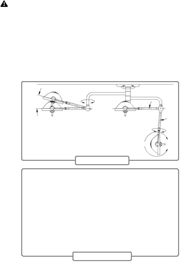
3.3HARMONY LA 300/500/700 LIGHTHEAD POSITIONING
CAUTION: Do not bump lightheads into walls or other equipment.
Lightheads can be positioned by using either the sterile handle, or by grasping the non-sterile handle around the lighthead housing. The following two paragraphs describe the positioning characteristics of the lighthead from outside or within the sterile field. To optimize shadow control, position the lighthead as appropriate before starting the intended surgical procedure.
Lighthead may (1) rotate continuously around vertical suspension tube; (2)rotate continuously around central hub; (3) rotate continuously about suspen-
sion arm; (4) tilt forward or backward in yoke approximately 310°; and (5) move up or down by pivoting at suspension elbow 15° up, and 85° down until vertical tube and suspension arm describe a straight line.
Monitor arms are capable of the following articulations: (1) rotate 300° at the central or secondary spindle; (2) rotate 330° at the horizontal extension arm; (3) rotate 320° a the yoke transition; (4) move up or down by pivoting at spring arm knuckle 20° up, and 40° down. Flat panel yoke also allows (5) tilt forward 15° or backward 75° in yoke. Additionally, the flat panel yoke can be rotated for either portrait or landscape display. See Figure 3-4.
15° Typical
Unlimited
85° Typical
Unlimited
310°
Lighthead Positioning
20°
300°
330°
40°
320° |
320° |
|
75° Up |
180° |
|
|
15° Down |
|
||
Portrait to |
13° |
||
|
Landscape
Monitor Arm Positioning
Figure 3-4. Suspension Positioning
3-3
764330-226

Rotate Handle
to Decrease
Rotate Handle
to Increase
Figure 3-5. Light Pattern Adjustment
3.4HARMONY LA 500 LIGHTHEAD PATTERN ADJUSTMENT
The illumination pattern for each lighthead can be adjusted to any diameter between the minimum and the maximum.
Adjust the light pattern by rotating the lighthandle clockwise to decrease pattern size.
Rotate the handle counterclockwise to increase pattern size.
NOTE: Typical lighthead positioning is above and slightly behind the surgeon’s right or left shoulder.
3.5LIGHTHANDLE AND LIGHTHANDLE COVER
3.5.1Installing and Using Lighthandle and Lighthandle Cover
WARNING – POSSIBLE PATIENT INJURY HAZARD: Failure to engage the lighthandle cover completely may result in cover falling from lighthead during the procedure.
Lighthandles are used to position Harmony LA 500 lightheads, allow access to intensity control on each lighthead, and to adjust lighthead pattern size. To
3-4
764330-226
avoid accidental contact with the non-sterile surgeon’s control buttons, the lighthandle should always be used with a disposable, sterile lighthandle cover (available separately from STERIS→).
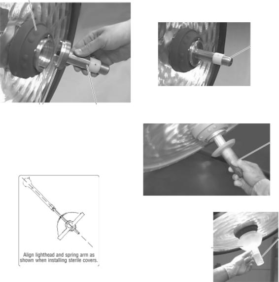
•If the lighthandle adapter is not already in place, align the tab on the adapter with the channel in the mounting ring and thread the adapter in until fully engaged. (See Figures 3-6a and 3-6b.)
•Prior to starting a procedure, ensure that the lighthandle is in place. Install the lighthandle by threading onto the adapter and firmly tightening. (See Figure 3-6c.)
•Remove the sterile lighthandle cover from its packaging and install onto the lighthandle. (See Figure 3-6d.)
•To ensure the lighthandle cover remains in place during the procedure, the groove in the cover must be fully engaged with the groove in the lighthandle.
•The lighthandle can be removed for cleaning or sterilization by unscrewing it from the handle adapter. The lighthandle can be sterilized using standard hospital cycles. Do not use the lighthead during a sterile procedure unless a disposable cover is installed on the lighthandle.
Surgeon's Control Buttons
Lighthandle
Adapter
Figure 3-6b.
Align Tab on Handle |
Lighthandle |
Adapter with Channel in |
Adapter |
Mounting Ring |
|
Figure 3-6a.
Figure 3-6c.
Lighthandle
Push Cover
Completely onto
Lighthandle
Disposable
Lighthandle
Cover
Figure 3-6d.
Figure 3-6. Standard Lighthhandle
3-5
764330-226
3.5.2METAL STERILIZABLE HANDLE
 WARNING-STERILITY ASSURANCE HAZARD: Do not use the surgeon’s control buttons unless a disposable sterile cover is installed. If the sterilizable lighthandle (metal) is used without a disposable cover, the surgeon’s control buttons are not protected by a sterile covering.
The metal sterilizable handle is used to position the Harmony LA lighthead and to adjust the light pattern size. The sterilizable handle may be used in place of a disposable sterile lighthandle cover.
The plastic lighthandle should be removed prior to installing the metal sterilizable handle. To do so,
simply unscrew it from the threaded handle adapter.
Prior to starting a procedure, install a clean, sterilized metal handle by screwing it onto the threaded handle adapter. Ensure handle is firmly tightened prior to use. The gap between the flange on the metal steriliizable handle and the surgeon’s control buttons prevent accidental contact with the non-sterile surface of the buttons.
The metal sterilizable handle can be removed for sterilization by unscrewing it from the adapter.
The metal sterilizable handle can be sterilized using standard hospital cycles steam cycles intended for lumens. Always sterilize handle between surgical procedures.
3-6
764330-226

Flat Panel Montior Support Arm with |
Flat Panel Montior Support Arm with |
Monitor in Landscape Position |
Monitor in Portrait Position |
Adjust CRT Monitor
Shelf by Loosening/
Tightening Knob
CRT Monitor Support Arm
Figure 3-7. Harmony Monitor Configurations
3.6 HARMONY LA MONITOR ARMS
The Harmony LA Surgical Lighting and Visualization System can be equipped with one or two monitor supportarms. Monitor arms can be included in the Harmony system either as the uppermostarm on the central spindle, or as the secondary spindle arm.
Refer to 3.3 Harmony LA Lighthead Positioning for positioning range details. See Figure 3-4.
Refer to separate Operating Instructions supplied with the monitor.
Signal and monitor power wiring is provided at the installation with each monitor support arm.
Input signals to monitors can be routed through the suspension wiring froman external video source (not by STERIS).
3-7
764330-226

|
|
|
Guide Disposable Cover |
|
|
|
Over Handle Until Handle Is |
Disposable Sterile Cover |
Closure Tie |
Monitor Yoke Handle |
Fully Covered |
|
|||
|
|
|
Cut Off and Discard Excess |
|
|
|
Closure Tie, If Desired. |
Figure 3-8. Installing Disposable Sterile Monitor Handle Covers
3.7INSTALL FLAT PANEL MONITOR YOKE HANDLE DISPOSABLE STERILE COVERS
WARNING – BIOHAZARD: Sterile disposables are intended for single use only. Universal precautions must be observed when disposing of any single use disposable item.
Important: Use new covers for each handle for each procedure where the monitor will be used. Covers are sterile and shipped in a protective wrapper. Wear sterile gloves when removing covers from packaging. When installing covers, follow sterilityassurance procedures as outlined by facility protocols.
Refer to Figure 3-8.
1.Remove cover from packaging.
2.Pull the cover until it fully covers the handle.
3.Pull closure tie until tight enough to prevent cover from slipping down the handle.
4.Repeat procedure for second handle.
3-8
764330-226

3.8VIDEO CAMERA INSTALLATION OR REMOVAL
3.8.1 Installation
1.Rotate lighthead until lens faces the room ceiling.
2.Remove the standard handle by unthreading it from the support mounting ring.
3.The camera is secured to the lighthead by threading it into the same support used by the standard handle.
a.Align the post with recess. This should align system connector properly. Install camera assembly to lighthead.
b.Select Camera Menu 1 on the control center.
c.Verify that all functions of the camera operate correctly using the control center. Verify functions using the optional wireless hand-held control or optional foot control, if applicable.
4.Once camera functions are verified, press the OFF touch pad on the face of the control center.
3.8.2 Removal
1.Rotate lighthead until perpendicular to floor.
2.Unthread camera housing from mounting ring and remove.
3.Install standard handle.
3.9LIGHTHEAD POSITIONING WITH VIDEO CAMERA
When the lighthead is used with a camera, a disposable sterile cover is placed over the camera housing. (Sterile cover is available from STERIS.)
Figure 3-10. Insta ll Camera Disposable Sterile Cover
Alignment Recess |
Alignment Post |
|
Threaded
Mounting Ring
Optional Video
Camera
Figure 3-9. Optional Camera Installation
3-9
764330-226
3.10VIDEO CAMERA OPERATION NOTE: At extreme wide angle, the image field pos-
The optional video camera is integrated into a removable handle that can be fitted to any Harmony LA 500 or 700 lighthead. Whenever the video option is used, a separated sterile disposable cover must be fitted over the camera before each procedure. This cover allows the camera to be grasped and used in the same way as a standard handle, including positioning the lighthead for optimal illumination, adjusting lighthead intensity and pattern size, as well as positioning the video image field for the best view of the procedure. The sterile cover must be removed from the camera and discarded after each procedure.
Video and control signals are turned on or off at the control center; any of the optional remote control units (see below) provide similar control functions. The control center also provides additional control for video brightness and contrast, color gain, stillimage capture and time and date display.
Three optional remote devices can control camera functions: a hand-held wireless control, Hermes voice-activated control (verbal commands and handheld pendant), or a foot control.
The control center functions by transmitting signals via a control cable to the camera located in the lighthead.
The optional wireless control functions by transmitting infrared signals to the control center. To initiate camera functions with either control, press the appropriate touch pad on the control face panel. The hand-held control’s IR (infrared) transmitter must be within approximately 15 feet maximum and 50° of the control center receiver. The control touch pads are used to control the following camera functions:
Zoom–for determining the level of detail visible in the image field. The Zoom function adjusts the image field continuously between two extremes:
+(Telephoto). At extreme telephoto, the camera captures an image showing great detail in a small area.
NOTE: At extreme telephoto, any motion of the lighthead/camera will be exaggerated (jerky). The field of focus has little depth at this extreme, forcing the Auto Focus function (if enabled) to refocus the camera when any object (such as a hand) enters the image field, or if camera position is adjusted. The camera is also sensitive to light level changes at extreme telephoto.
–(Wide Angle). At extreme wide angle, the camera captures a large, image with less detail than telephoto.
sesses a greater depth of focus and less sensitivity to light level changes.
Rotate–Use this function to change orientation of the video field. Image field can be rotated in either clockwise or counterclockwise directions.
Bright–Use this function to affect the overall brightness (or darkness ) of the video image. The Bright control can be set to adjust itself automatically.
Manual Focus–Use this function to manually set the focus for close-up shots or other special applications. The Auto Focus function must be toggled off to enable manual focusing. Adjust the clarity of focus by pressing the + or – touch pads.
NOTE: + touch pad moves the lens slightly closer to subject; – touch pad moves the lens slightly away from subject.
Auto Focus – Use this function to toggle Auto Focus on or off. When Auto Focus is ON, the camera automatically focuses on the object in the image field closest to the camera lens. When Auto Focus is turned OFF, the camera maintains focus on the last object upon which it was focused, until Auto Focus is turned back on.
NOTE: It may be necessary to toggle Auto Focus OFF when using the camera at extreme telephoto (close up), to prevent the camera from refocusing on hands and other objects introduced into the image field while videoing procedures.
Red Gain/Blue Gain – These controls are used to adjust image color settings, and are intended to allow the user to compensate for changes in color temperature provided by differing light sources. The gain control can be set to adjust automatically.
3.10.1HERMES-Ready Control Center
The Hermes Control Center functions by transmitting signals through an interface cable connected to the wall control. When used, the interface cable should be routed to avoid surgical personnel foot traffic. The control center is intended to allow personnel within the sterile field to operate all camera functions using verbal commands or a hand-held pendant. Refer to the Hermes operating manual for more information.
3.10.2Optional Foot Control
The foot control functions by transmitting signals through a cable connected to the control center. When the foot control is used, the cable should be routed to avoid surgical personnel foot traffic. The foot control is intended to allow personnel within
3-10
764330-226

the sterile field to operate the zoom and rotation functions of the camera.
Foot control is used to control zoom and rotation functions. Press on appropriate sides of foot pedals to activate foot control functions. Functions controlled through the foot control unit are identical to those controlled through the optional hand-held wireless control or control center.
3.11GUIDELINES FOR MAXIMIZING VIDEO IMAGE
The following steps will aid in maximizing video imaging effectiveness.
1.Energize the light at medium setting on the control center, and position the lighthead approximately 39" (1000 mm) from the surgical site.
2.Using the hand-held remote, or the control center, zoom in or out (+ or -) until the desired image fills the viewing screen of the monitor.
NOTE: Zooming completely out causes image distortion within the illuminated area.
3.If the light pattern (white circle) does not fill the monitor’s screen (shaded square), the image inside the pattern will be distorted.
4.Reposition the camera to orient the focal point (center of the desired image) at the center of the viewing screen.
Adjust zoom and rotation as needed:
5.The camera may be zoomed to the full 10x zoom and rotation orientation adjusted as needed.
6.Clockwise and/or counterclockwise orientation is adjusted by using the curved arrow(s) on the hand-held control, the control center or the optional foot control.
3.11.1Engage Manual Focus
As instruments are introduced to and removed from the surgical field, the auto focus will attempt to focus on the nearest object, possibly causing the image to blur intermittently. To prevent this effect, once the camera has been positioned and focused onto the surgical site, the manual focus mode may be engaged to maintain image clarity during the procedure.
For deep cavity illumination, it may be necessary to engage the manual focus to focus beyond the nearest object (i.e., the surface area surrounding the incision) so that the desired image can be viewed clearly.
Amsco® SQ240 SurgiVisionTM
Surgical Lighting and Video System
ZOOM |
ROTATE |
|
|
|
|
|
|
|
|
|
|
|
|
|
|
|
|
|
|
|
|
|
|
|
|
|
Optional Hand-held Wireless |
|
|
|
|
|
|
Optional Foot Control |
|||
|
Remote Control |
|
|
|
|
Figure 3-11. Optional Camera Controllers
3-11
764330-226
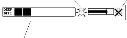
3.12DeepSite CONTROL CENTER STATUS INDICATORS
NOTE: See DeepSite Maintenance Manual P764330210 for more information on the DeepSite Light.
3.12.1Intensity Level Status
This shows the current intensity level of the DeepSite light.
3.12.2Lamp Life Status
The DeepSite lighthead uses a high-intensity Xenonlamp module as a light source. The Harmony
LA Surgical Lighting and Visualization System can track the approximate life remaining for this lamp module and display it at the Control Center.
NOTE: Refer to Lamp Replacement procedure in Section 6 of this manual when it becomes necessary to replace the lamp.
|
|
|
Approximate Lamp Life |
|||||
|
|
|
|
Used/Remaining |
||||
New Lamp |
|
|
|
|
Spent Lamp |
|||
|
|
|
|
|
|
|
|
|
|
|
|
|
|
|
|
|
|
|
|
|
|
|
|
|
|
|
|
|
|
|
|
|
|
|
|
|
|
|
|
|
|
|
|
|
|
|
|
|
|
|
|
|
|
DeepSite Lamp Life
Status Indicator
DeepSite Intensity Status
Indicator
Figure 3-12. DeepSite Control Center Indicators
3-12
764330-226

Section 4: Service Mode
4.1 SERVICE MODE PROCEDURE
1.The context-sensitive switch under the "Lights" description field shall change the LCD display to the Light Control screen.
4.2 SERVICE MENU 1 SCREEN
Service screens shall be available to service personnel for diagnostics and firmware updates of the wall control and lighthead units. The service screens shall be accessible by performing the following sequence:
1.Turn power ON by pressing systems button.
2.Bring up the System Menu by pressing systems button.
3.Push and hold the ON button used to place the Wall Control Unit into the Active Mode.
4.Depress the Select Function Up button.
After performing the sequence described above, the first of a series of Service Menus shall be displayed. Service Menu 1, shown in Figure 4-1, is used to read the firmware part number and revision for the wall control unit and all installed lightheads.
Figure 4-1. Service Menu 1 Screen
2.The context-sensitive switch under the "Menu 2" description field shall change the LCD display to the Service Menu 2 screen.
3.The pointer (triangle on left side of lighthead) shall not be affected by the depression of the Up/Down button.
4.The Left/Right buttons under the lighthead field shall select the lighthead whose firmware part numbers are to be displayed. If a lighthead is not installed, the message "Not Installed" shall be displayed in the area where the firmware part numbers are displayed.
5.The lighthead numbers shall correspond to the serial communication port/head numbers at the Hub Interface PWB.
6.The three TYPES of lightheads shall be Small, Medium, or Large.
4-1
764330-226

4.3 SERVICE MENU 2 SCREEN
Service Menu 2, shown in Figure 4-2, shall be used to display the programmed power and operating performance for all of the lighthead units installed.
1.The context-sensitive switch under the "Lights" description field shall change the LCD display to the Light Control screen.
2.The context-sensitive switch under the "Menu 3" description field shall change the LCD display to the Service Menu 3 screen.
3.The context switch Reset Temp shall send a command to all lightheads to clear the stored maximum temperature reading.
4.The Lamp numbers shall correspond to the serial communication port/Head numbers at the Hub Interface PWB.
5.The Left/Right buttons under Lamp shall be used to select the lighthead lamp whose intensity is to be selected with the Up/Down buttons.
6.The Up/Down buttons under Power shall be used to adjust the intensity (from off to a maximum intensity of 7) of the selected lighthead lamp. Depressing and holding the Down button for more that two seconds shall turn the lamp off. If a lamp is off, depressing the Up button shall turn the lamp on at its last intensity setting.
7.The duty cycle listed is in units of percent and is rounded off to the nearest integer (less than 0.5% is rounded down, 0.5% or greater is rounded up).
Intensity Setting of Lighthead 1-7
Power in Watts
Lamp Voltage in 22-24 V
Current to Lamp
Duty Cycle of Lamp Control Board
Temperature on Control Board, °C
Maximum Temperature seen on Control Board, °C
Figure 4-2. Service Menu 2 Screen
4-2
764330-226
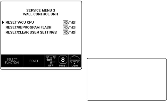
4.4 SERVICE MENU 3 SCREEN
Service Menu 3, shown in Figure 4-3, shall be used to force the Wall Control Unit to undergo a soft reset, place the unit into a mode for reprogramming Flash memory with updated firmware, or reinitialize user settings, such as lamp intensities, in non-volatile RAM.
5.Depressing the Right buttons under Reset shall cause the Wall Control Unit to reset and perform the selected function.
RESET WCU CPU – The WCU performs the same startup, testing, and display of messages as if the power was applied to the system.
RESET/REPROGRAM FLASH – After changing screen choice to "Yes," the WCU will startup and wait for a new application to be downloaded from a PC running STERIS AppLoad. As an alternative, the power can be turned off (at the incoming ac voltage rocker switch in the rough-in box) to the wall control, the AppLoad program started, then upon turning the wall control back on, the software will automatically download.
RESET/CLEAR USER SETTING – The WCU performs the same startup, testing, and display of messages as if the power was applied to the system. The only difference is that the user settings for the following will be set to default values.
Figure 4-3. Service Menu 3 Screen
1.The context-sensitive switch under the "Lights" description field shall change the LCD display to the Light Control screen described in SECTION 4.2.
2.The context-sensitive switch under the "Menu 1" description field shall change the LCD display to the Service Menu 1 screen described in SECTION 4.2.
3.Control of the Ambient Light is described in SECTION
5.2.7.
4.The Up/Down buttons under the Select Function shall select the type of Wall Control Reset.
4-3
Table 4-1. Control Center Default Values
LANGUAGE: |
ENGLISH |
AMBIENT LIGHT |
NOT INSTALLED |
|
|
AMBIENT LIGHT MODE |
MANUAL |
|
|
AMBIENT LIGHT |
OFF |
|
|
CAMERA ZOOM SPEED |
3 |
CAMERA FOCUS SPEED |
1 |
|
|
LCD CONTRAST |
Nominal |
|
|
764330-226
Loading...