

Page 1
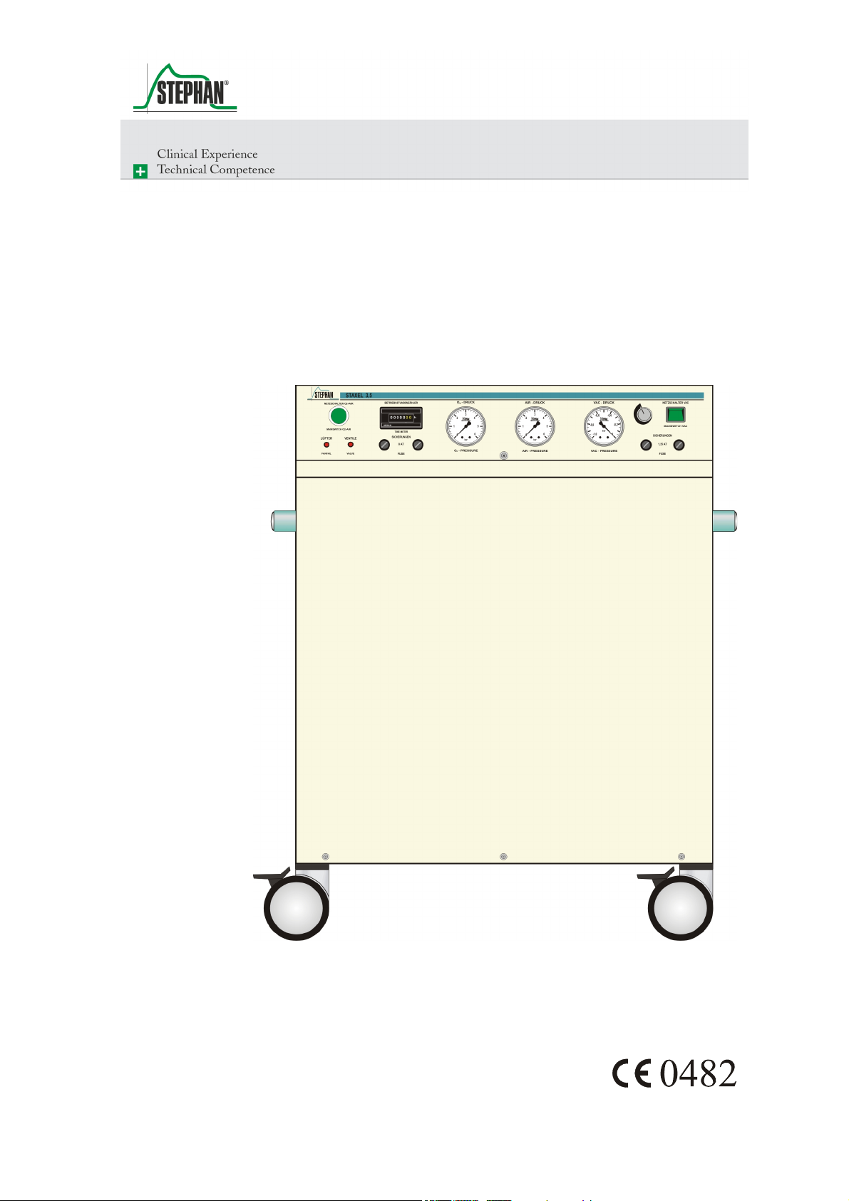
Staxel 3.5
O2AIR Energy Supply Module
Operating Manual
Page 2

Preface
Operating manual
This operating manual intends to provide clear answers to any questions
about how to use and care for S
TAXEL 3.5.
This operating manual does not contain any instructions for repairs and
installation.
In the event of any faults during operation, please contact the authorized
customer service of F. S
TEPHAN GMBH or the authorized dealer who
delivered the device to you and provided you with the initial instructions
on how the device functions and how to operate it.
The manufacturer only warrants the safety and reliability of S
TAXEL 3.5,
if it is operated in conformity with the operating manual.
F. Stephan GmbH
- Medizintechnik Kirchstrasse 19
56412 Gackenbach
Subject to technical alterations.
as of: Januar 2006
version: V1.0
2 GA-602-0106V1.0-PAE-GB © F. Stephan GmbH
Page 3

®
Contents
Contents .....................................................................................................3
1 General information ...........................................................................5
1.1 Product combination................................................................5
1.2 Device name and manufacturer ...............................................5
1.3 Proper use ................................................................................6
1.4 Packaging and waste disposal..................................................6
1.5 Introduction .............................................................................7
1.6 Abbreviations and definitions..................................................8
1.7 Technical data..........................................................................9
2 Safety instructions............................................................................11
2.1 Danger warnings....................................................................11
Contents
2.2 Warnings................................................................................12
3 Structure and description of functions .............................................13
3.1 Front view..............................................................................13
3.2 Controls and display elements...............................................14
3.3 Rear view...............................................................................15
3.4 Right-hand side view .............................................................16
3.5 Left-hand side view ...............................................................17
4 Preparing for operation ....................................................................19
4.1 Erecting the device ................................................................19
4.2 Connecting to the gas and power supply ...............................20
4.2.1 Gas supply .................................................................20
4.2.2 Power supply .............................................................20
5 Test list.............................................................................................23
5.1 Test before starting the device every time .............................23
5.2 Test before every patient .......................................................23
6 Operation .........................................................................................25
6.1 Switching on..........................................................................25
6.2 Switching off .........................................................................25
6.3 Stopping the device ...............................................................25
7 Troubleshooting ...............................................................................27
8 Care and maintenance ......................................................................29
© F. Stephan GmbH GA-602-0106V1.0-PAE-GB 3
Page 4

ContentsContents
8.1 Disinfection and sterilisation .................................................29
8.1.1 Device housing, gas connections, mains lead ...........30
8.2 Safety checks .........................................................................30
8.3 Maintenance...........................................................................30
8.3.1 Filter unit ...................................................................31
9 List of accessories............................................................................33
10 Guarantee .........................................................................................35
11 List of illustrations ...........................................................................37
12 List of tables.....................................................................................39
13 Notes ...............................................................................................41
4 GA-602-0106V1.0-PAE-GB © F. Stephan GmbH
Page 5

®
1 General information
1.1 Product combination
Combinations with other products can impair the performance and safety
of S
TAXEL 3.5.
TEPHAN GMBH rules out any warranty for unacceptable device
F. S
combinations operating with products not approved by the manufacturer
or products without certified compatibility.
Only use the accessories stated in chapter 9 on page 35.
1 General information
1.2 Device name and manufacturer
TAXEL 3.5
Device name
Manufacturer
S
F. Stephan GmbH
- Medizintechnik Kirchstrasse 19
56412 Gackenbach
(+)49 (6439) 9125 – 0
(+)49 (6439) 9125 – 111
info@stephan-gmbh.com
www.stephan-gmbh.com
© F. Stephan GmbH GA-602-0106V1.0-PAE-GB 5
Page 6

1 General information
1.3 Proper use
Oxygen concentrators provide a safe source of oxygenated air for patients
needing it. These devices increase the level of oxygen by filtering out the
nitrogen from the ambient air.
S
TAXEL 3.5 constantly generates oxygen from the ambient air and offers
an economic alternative to bottled or liquid oxygen.
S
TAXEL 3.5 is used to generate oxygen and to produce compressed air
and vacuum; it is designed primarily for operating ventilation and
anesthesia systems.
Other combinations are also available on request or order.
1.4 Packaging and waste disposal
Packaging
Return/disposal
The device packaging consists essentially of recyclable or reusable
materials.
The carton packaging can be reused or disposed of as used paper.
The wrapping consists of CFC-free padding which can be disposed of
together with the foil as recyclable plastic waste (in Germany: yellow
trash can).
F. S
TEPHAN GMBH guarantees that used devices from our company can
be returned free of charge and disposed of correctly, thus making a
contribution to the environment.
6 GA-602-0106V1.0-PAE-GB © F. Stephan GmbH
Page 7

®
1.5 Introduction
German legislation
The Medical Devices Law (MPG), the Medical Devices Operator
Ordinance (MPBetreibV) and the Law on Technical Working Equipment
stipulate that the operator's attention must be drawn to the following:
The device must only be operated by skilled staff who must have
an exact knowledge of the operating manual.
Only use the device for the intended purpose described in the
operating manual.
Read the operating manual through carefully and comply with its
instructions, because lasting safety for patient and user is only
warranted when the device is operated perfectly.
The operating manual must be kept constantly available at the
place of use.
Faulty care and operation can cause work stoppages and
accidents.
1 General information
Warranty
The manufacturer does not accept any warranty claims resulting from
incorrect operation or inadequate care and maintenance.
The manufacturer only guarantees the safety and reliability of the device
if it is operated in compliance with the operating manual.
© F. Stephan GmbH GA-602-0106V1.0-PAE-GB 7
Page 8

1 General information
1.6 Abbreviations and definitions
Abbrevations Definition Meaning
AIR Medical compresed air
bar Unit of measurement for compressed
air
DIN German standardization institute
EN European standard
Flow Volume flow
LED Light Emitting Diode
min minutes Unit of time
O2 Oxygen
OG Upper limit
s seconds Unit of time
UG Lower limit
VAC Vacuum
Tab. 1: Abreviations and definitions
8 GA-602-0106V1.0-PAE-GB © F. Stephan GmbH
Page 9

®
1.7 Technical data
Ambient conditions
General
Operation Temperature 15 – 40 °C
Storage Temperature 5 – 60 °C
MPG class
1 General information
Rel. humidity 30 – 85 %
Air pressure 900 – 1060 hPa
Bring to room temperature before starting to
operate the device.
Rel. humidity 10 – 100 %
Air pressure 700 – 1060 hPa
Store in a protected, dust-free place protected
from moisture and frost
II b
Power supply
Specifications
Protection class
Inspection/maintenance
cycle
Dimensions (WxHxD)
Weight
I type B as per DIN EN 60601-1 :March 1996
annual
610 x 820 x 680 mm
122 kg
Mains Connection 230 V AC
50 – 60 Hz
Input power 6 A
Device fuses 2 x 8 AT
2 x 1.25 AT
Absorber unit Pressure 2.2 bar
Changeover cycle 11 s
Flushing time 2 s
O2 AIR
System pressure 5.2 bar 5.2 bar
Output pressure 3.8 bar 3.8 bar
Consumption 6 l/min 8 l/min
Max. consumption 7 l/min 13 l/min
© F. Stephan GmbH GA-602-0106V1.0-PAE-GB 9
Page 10

1 General information
Compressed air
compressor
Compressor for post-
compression
Flat fan
Parameters
Voltage
Motor speed/output
Capacitor
Voltage
Motor speed/output
Capacitor
Voltage
Motor speed
Input power
Noise level
Dimensions
Pressure gauge O
230 V / 50 Hz
1350 rpm / 435 Watt
15 μF
230 V / 50 Hz
1390 rpm / 435 Watt
15 μF
230 V / 50 Hz
2800 rpm
45 VA
48 dB
150 ∅ x 55 mm
0 – 6 bar
2
AIR 0 – 6 bar
VAC -1 – 0 bar
O
concentration
2
Monitoring
Flow [l/min] O2 concentration [%]
1 – 2 95
3 – 6 94
7 90
8 88
9 80
Tab. 2: Available O2 concentration at corresponding flow
Parameter Unit UG OG
Pressure sensor bar 2.5 5.5
Temperature sensor °C 45
Pressure relief valve bar 5,5
Tab. 3: Alarm limits
Alarm visual, acoustic
10 GA-602-0106V1.0-PAE-GB © F. Stephan GmbH
Page 11
®
2 Safety instructions
Refers to instructions drawing attention to important facts.
The following safety instructions are repeated at relevant points in the
operating manual and must always be heeded.
Refers to dangers which, if not heeded, can result in life-threatening
injuries to the patient and/or operator.
Danger
2 Safety instructions
Refers to warnings which, if not heeded, can result in malfunctions,
damage or defects in the device, which can possibly also put the patient at
Warning
Caution
danger.
Refers to precautions which, if not heeded, can result in damage to the
device and its accessories.
2.1 Danger warnings
The device must be operated according to the instructions in this
operating manual.
Danger
S
TAXEL 3.5 is not certified for use in explosion-risk areas.
Danger
© F. Stephan GmbH GA-602-0106V1.0-PAE-GB 11
Page 12
2 Safety instructions
Danger
S
TAXEL 3.5 must not be operated in the vicinity of naked flames or
glowing objects, given the increased explosion risk from the
concentration of pure oxygen in the device.
The device must not be used when damaged. Disconnect from the mains.
Danger
Always disconnect the device from the mains immediately in any
dangerous situations or when technical faults occur.
Danger
2.2 Warnings
When moving the device, ensure that the wheel brakes have been
released and are applied again when set upright.
Warning
DIN EN 60601-1 resp. VDEO 0751-1 must be heeded in particular for
medical technical devices with electrical connection. Accordingly, these
Warning
devices must only be repaired by the manufacturer or an entity explicitly
authorized for this purpose by the manufacturer.
The provisions of DIN EN 60601-1 must be heeded when connecting
external electrical devices.
Warning
Only the authorized customer service of F. S
TEPHAN GMBH is allowed to
alter, modify, repair or open the device. This also includes replacing the
Warning
bacteria filter, intake filter and intake filter mat in accordance with the
operating manual. Use only spare parts from F. S
TEPHAN GMBH for
maintenance.
12 GA-602-0106V1.0-PAE-GB © F. Stephan GmbH
Page 13
®
3 Structure and description of functions
3 Structure and description of functions
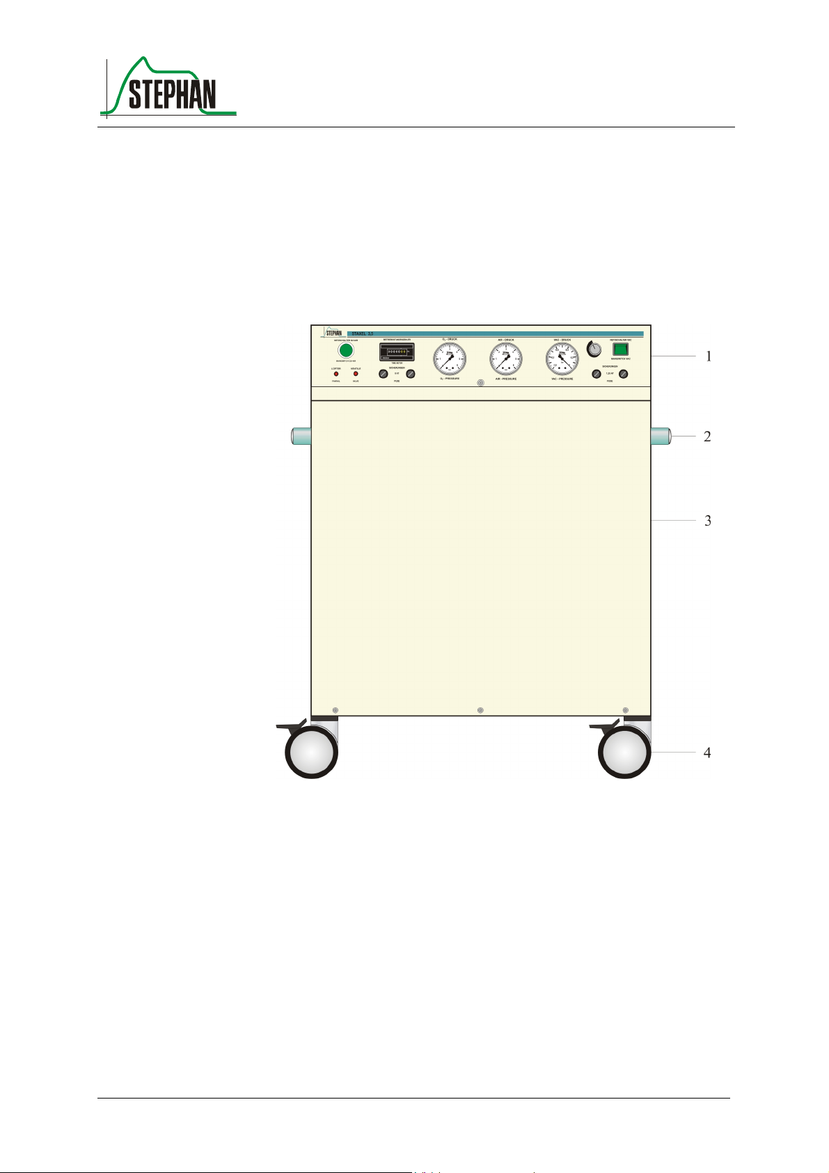
3.1 Front view
Fig. 1: Front view
1 Controls and display elements 3 Housing jacket
2 Handles 4 Rollers (4, 2 can be fixed)
© F. Stephan GmbH GA-602-0106V1.0-PAE-GB 13
Page 14

3 Structure and description of functions
3.2 Controls and display elements
Fig. 2: Controls and display elements
1 Mains switch "On/Off" for O
2 Operating hours counter for O
3 Pressure gauge for O
pressure display
2
and AIR
2
and AIR generation
2
4 Pressure gauge for AIR pressure display
5 Pressure gauge for VAC pressure display
6 Knob for regulating the vacuum
7 Mains switch "On/Off" for VAC
8 Fuse for VAC generation
9 Fuse for O
and AIR generation
2
10 Visual alarm for failure of electronic components or switching valves
11 Visual alarm for overheating
14 GA-602-0106V1.0-PAE-GB © F. Stephan GmbH
Page 15

®
3.3 Rear view
3 Structure and description of functions
Fig. 3: Rear view
1 Intake filter mat 5 Membrane dryer
2 Power sockets (230 V AC) 6 Acoustic alarm
3 Connection lead 7 Water separator
4 Filter 8 Filter unit
© F. Stephan GmbH GA-602-0106V1.0-PAE-GB 15
Page 16

3 Structure and description of functions
3.4 Right-hand side view
Fig. 4: Right-hand side view
1 O
outlet 2 AIR outlet
2
16 GA-602-0106V1.0-PAE-GB © F. Stephan GmbH
Page 17

®
3.5 Left-hand side view
3 Structure and description of functions
Fig. 5: Left-hand side view
1 O
outlet 3 VAC outlet
2
2 AIR outlet
© F. Stephan GmbH GA-602-0106V1.0-PAE-GB 17
Page 18

Page 19

®
4 Preparing for operation
4.1 Erecting the device
S
TAXEL 3.5 with rollers
S
Caution
TAXEL 3.5 is supplied on rollers.
The front rollers of the device are equipped with parking brakes to
prevent any unintended movement of S
Press lightly on the brake lever to activate the parking brake by blocking
the rollers. Lift the brake lever with the tip of your foot to release the
parking brake again.
When moving the device, ensure that the wheel brakes have been
released and are applied again when set upright.
TAXEL 3.5.
4 Preparing for operation
Information
S
TAXEL 3.5 must only be erected and operated in dry, well-ventilated
rooms with low dust levels. Moist or wet environments can drastically
impair the functioning of the device. Ensure in particular that there are no
containers filled with water or similar in the immediate vicinity.
When choosing the site for erecting the device, make sure there is easy
access for operation, cleaning and maintenance.
The ambient temperature should never exceed +40° C. For relative
humidity levels exceeding 70%, it is advisable to operate the device only
in air-conditioned rooms.
The air intake grids on the back of the device must not be covered or any
objects placed on them.
There should be spacing of at least 10 cm to the wall at the rear of the
device.
© F. Stephan GmbH GA-602-0106V1.0-PAE-GB 19
Page 20

4 Preparing for operation
R
4.2 Connecting to the gas and power supply
4.2.1 Gas supply
Check the pressure gauge on the front to see whether there is sufficient
pressure. The needle must show more than 3 bar.
Connections for O
and
2
AI
The outlets for O
connections are quick-release couplings which lock automatically when
connected.
To pull the tube out of the connection, at the same time press the
unlocking pin on top of the connection.
Connection for VAC
The outlet for vacuum is on the right of the device. The connection is a
1/8" tube nozzle. Simply insert the tube to the intake unit.
4.2.2 Power supply
S
TAXEL 3.5 runs on 230 V AC.
1. Connect the mains lead at the rear of the device to the power socket
on the wall.
2. Switch on the power switch "On/Off" for O
the device. The switch lights up green.
3. Switch the power switch "On/Off" for VAC on the front of the device.
The switch lights up green.
and AIR are on the two sides of STAXEL 3.5. The
2
and AIR on the front of
2
Electrical accessories
Electrical accessories can be connected to the 4 auxiliary power sockets.
The auxiliary power sockets are switched on with the mains switch
"On/Off" for O
and AIR on the front of the device.
2
When in use, S
TAXEL 3.5 can only have max. 4 user-accessible auxiliary
power sockets.
Warning
20 GA-602-0106V1.0-PAE-GB © F. Stephan GmbH
Page 21

®
Warning
Warning
4 Preparing for operation
No not connect any further multiple power sockets, e.g. socketa dapters,
to the auxiliary power sockets.
Mains failure also means failure of the auxiliary power sockets,
© F. Stephan GmbH GA-602-0106V1.0-PAE-GB 21
Page 22

Page 23

®
f
5 Test list
5 Test list
All relevant tests must be carried out before using the device. The staff
carrying out the test must have exact knowledge of the operating manual.
Prerequisites for the
test
5.1 Test before starting the device every time
Check pressure
The device is completely assembled and connected up.
Remove all tubes from the connections
Visually check the pressure gauge for O
All pressure must be in the correct range ( > 3 bar ).
and AIR
2
Check condition o
device
Check the device for any signs of damage
Check the mains lead and electrical devices for any external signs of
damage
Visually check the LEDs
5.2 Test before every patient
concentration
2
Danger
Check O
Visually check the pressure gauge for O
All pressure must be in the correct range ( > 3 bar )
The device must not be used if it fails any of the tests!
and AIR
2
© F. Stephan GmbH GA-602-0106V1.0-PAE-GB 23
Page 24

Page 25

®
6 Operation
6.1 Switching on
Only switch the device on if it is not pressurized!
1. Switch on the mains switch "On/Off" for O2 and AIR on the front of
the device.
2. S
TAXEL 3.5 starts to generate oxygen and compressed air
3. The pressure in the corresponding pressure gauges for oxygen and
compressed air on the front panel increases to 3.5 bar.
6 Operation
4. Switch on the mains switch "On/Off" for VAC on the front of the
device.
5. S
TAXEL 3.5 starts to generate vacuum.
6.2 Switching off
1. Switch off the mains switch "On/Off" for O
the device.
2. Pressure is released from the tanks.
3. Switch off the mains switch "On/Off" for VAC on the front of the
device.
6.3 Stopping the device
1. Switch off the mains switch "On/Off" for O
the device.
and AIR on the front of
2
and AIR on the front of
2
2. Pressure is released from the tanks.
3. Switch off the mains switch "On/Off" for VAC on the front of the
device.
4. Remove all tubes from the connections.
5. Disconnect the device from the mains.
© F. Stephan GmbH GA-602-0106V1.0-PAE-GB 25
Page 26

Page 27

®
7 Troubleshooting
Fault Cause Remedy
No pressure for O2 and
compressed air, acoustic alarm
Initial pressure of O2 or
compressed air falls below 2.5
bar, acoustic alarm
Red LED "Visual overheating
alarm" (Fig. 2) on, the device
stops working
No power supply
Fuse defect
Fine filter clogged
Gas consumption too high
Compressor defect
Tube leaks
STAX EL 3.5 overheated
Insufficient air flow to cool
the capacitor
Check power supply
Replace fuse
Replace fine filter
Reduce gas consumption
Inform F. S
customer service
Replace filter mat
Check that fan works
properly, replace if necessary
7 Troubleshooting
TEPHAN GMBH
Red LED "Visual alarm for
failure of electronic component
or switching valves« (Fig. 2) is
on
O2 concentration falls below
minimum value
Tab. 4: Troubleshooting
Valves not switching correctly
Electronic component defect
Compressor defect
Supply tube torn off
Balance of pressure between
the two absorber tanks no
longer balanced
Outdated absorber tanks
Inform F. S
TEPHAN GMBH
customer service
Readjust absorber
Flow too high
Replace absorber tanks
© F. Stephan GmbH GA-602-0106V1.0-PAE-GB 27
Page 28

Page 29

®
8 Care and maintenance
8.1 Disinfection and sterilisation
As with operation of the device, it must only be cleaned and disinfected
by instructed members of staff.
Caution
Proceed with routine cleaning at regular intervals according to the local
hospital routine.
All disposable parts must be disposed of in an environment-friendly
manner according to the local hospital routine.
8 Care and maintenance
Caution
Caution
Caution
All instrument and surface disinfectants based on alcohol and aldehyde
may be used.
Do not use deoxygenating or dechlorinating disinfectants or disinfectants
containing phenol or its derivatives.
Amino derivatives can damage soft plastics (tubes).
All used disinfectants must be certified in accordance with relevant
environmental legislation.
Always comply with the regulations for handling cleaning agents and
disinfectants issued by the Professional Association.
When using cleaning agents and disinfectants, pay attention to correct
concentrations and reaction times as otherwise damage to the materials
cannot be ruled out.
When using effective substances other than those stated, please contact
the manufacturer of the disinfectant to obtain compatibility confirmation.
Caution
© F. Stephan GmbH GA-602-0106V1.0-PAE-GB 29
Page 30

8 Care and maintenance
8.1.1 Device housing, gas connections, mains lead
Cleaning
Procedure
Wiping disinfection
1. Wipe down the surfaces with ready made-up disinfectant solution
(surface disinfectant).
2. The cloth should be no more than damp.
3. No moisture must be allowed to penetrate in the device.
8.2 Safety checks
Safety checks are to be carried out every twelve months by the
manufacturer or the authorized customer service for F. S
8.3 Maintenance
For reasons of device safety, it is advisable to proceed with maintenance
of S
TAXEL 3.5 after every approx. 1000 operating hours but at least every
twelve months together with the safety checks.
TEPHAN GMBH.
Maintenance is to be carried out by the authorized customer service for F.
S
TEPHAN GMBH.
After 10,000 operating hours, arrange for a general overhaul to be carried
out by the authorized customer service for F. S
Only use spare parts from F. S
TEPHAN GMBH for maintenance.
TEPHAN GMBH.
30 GA-602-0106V1.0-PAE-GB © F. Stephan GmbH
Page 31

®
8.3.1 Filter unit
Fig. 6: Exploded drawing intake filter
8 Care and maintenance
Changing the bacteria
filter
1 Holder 4 Intake filter
2 3-ply bacteria filter 5 Housing flange
3 Stainless steel fine sieve 6 Tube for housing flange
The bacteria filter for room air must be replaced and the intake filter mat
cleaned every 10 days or after every 250 operating hours. Please note that
these intervals can be drastically reduced depending on the contamination
levels in the ambient air.
At the beginning, please check the condition of the bacteria filter every 23 days to reduce the changing intervals if necessary. The bacteria filter
must be changed when it goes gray.
1. Pull the holder out of the housing flange.
2. Remove the 3-ply bacteria filter and replace with a new bacteria filter
(in S
TAXEL 3.5 spare parts set).
3. Replace the holder again.
Check the intake filter integrated in the intake filter housing every time
after changing the 3-ply bacteria filter. If the bacteria filter is changed too
late, the intake filter can become clogged with dust particles so that the
air supply to the compressors is drastically reduced. This can result in a
rapid fall in the O
concentration of STAXEL 3.5.
2
© F. Stephan GmbH GA-602-0106V1.0-PAE-GB 31
Page 32

8 Care and maintenance
Changing the intake
filter
1. Pull the holder out of the housing flange.
2. Remove the 3-ply bacteria filter.
3. Remove the stainless steel fine sieve.
4. Unscrew the intake filter and screw in a new one (in S
spare parts set).
5. Put the stainless steel fine sieve in again.
6. Insert the 3-ply bacteria filter.
7. Put the holder back in again.
The intake filter cannot be cleaned!
TAXEL 3.5
32 GA-602-0106V1.0-PAE-GB © F. Stephan GmbH
Page 33

®
9 List of accessories
Pos. Designation Art. No. Quantity (ea)
1 Fuses 8 A ( T ) 1 804 60 026 2
2 Fuses 1.25 A ( T ) 1 804 60 004 2
3 3-ply bacteria ultra-fine filter 1 600 60 115 6
4 Intake filter mat 1 600 61 123 6
5 Intake silencer & bacteria
filter
6 O ring 4.47 x 1.78 EPDM 1 950 60 031 10
7 Filter insert for moisture
filter
9 List of accessories
1 600 40 046 6
1 925 60 362 3
Tab. 5: List of accessories
© F. Stephan GmbH GA-602-0106V1.0-PAE-GB 33
Page 34

Page 35

®
10 Guarantee
The manufacturer F. S
the date of purchase.
Any intervention in the device or repairs must only be carried out by F.
S
TEPHAN GMBH or an authorized expert. Otherwise the guarantee
becomes null and void.
The guarantee also becomes null and void if the device is handled
incorrectly.
10 Guarantee
TEPHAN GMBH grants a 24 month guarantee from
© F. Stephan GmbH GA-602-0106V1.0-PAE-GB 35
Page 36

Page 37

®
11 List of illustrations
Fig. 1: Front view.................................................................................... 13
Fig. 2: Controls and display elements ..................................................... 14
Fig. 3: Rear view..................................................................................... 15
Fig. 4: Right-hand side view ................................................................... 16
Fig. 5: Left-hand side view ..................................................................... 17
Fig. 6: Exploded drawing intake filter .................................................... 31
11 List of illustrations
© F. Stephan GmbH GA-602-0106V1.0-PAE-GB 37
Page 38

Page 39

®
12 List of tables
Tab. 1: Abreviations and definitions......................................................... 8
Tab. 2: Available O2 concentration at corresponding flow ..................... 10
Tab. 3: Alarm limits ................................................................................ 10
Tab. 4: Troubleshooting .......................................................................... 27
Tab. 5: List of accessories....................................................................... 33
12 List of tables
© F. Stephan GmbH GA-602-0106V1.0-PAE-GB 39
Page 40

Page 41

®
13 Notes
13 Notes
© F. Stephan GmbH GA-602-0106V1.0-PAE-GB 41
Page 42

F. Stephan GmbH
- Medizintechnik Kirchstrasse 19
56412 Gackenbach
(+)49 (6439) 9125 – 0
(+)49 (6439) 9125 – 111
info@stephan-gmbh.com
www.stephan-gmbh.com
 Loading...