

Page 1
STEPHAN
O2-AIR-ENERGY SUPPLY MODULE
STAXEL 1,5 3,5
°
Modul für Intensiv-Therapie
BETIEBSTUNDENZÄHLER
LÜFTER
SERVICE MANUAL
RÜCKWAND
F. STEPHAN GmbH · Medizintechnik · D-56412 Gackenbach · Kirchstr. 19 · Tel. (06439) 9125-0 · Fax (06439) 9125-111 · info@stephan-gmbh.com ·
www.stephan-gmbh.com
Page 2

STAXEL O2 and AIR Service Manual
Table of contents
2. TECHNICAL DIMENSIONS
4
3.1 Production of oxygen 5
3.2 Production of compressed air 5
3.3 Generation of vacuum 6
3.4 Construction 6
4. INSTALLATION AND STARTUP 7
4.1 Environmental conditions 7
4.2 Startup 8
5. CONTROL – AND DISPLAY ELEMENTS 9
6. CONNECTIONS FOR OXYGEN, COMPRESSED AIR AND VACUUM10
7. TECHNICAL DESCRIPTION 11
7.1 Description of system 11
7.2 Schematic representation 12
7.3 Switching attitude of the valve unit 13
8. TECHNICAL DETAILS 15
9. PERFORMANCE DATA OF STAXEL 16
10. ERROR DETECTION SYSTEM 17
11. MAINTENANCE 18
12. GUARANTEE 18
13. SERVICE 19
1
Page 3

STAXEL O2 and AIR Service Manual
13.1 Power supply 19
13.2 Wiring diagram, STAXEL bottom part 20
13.3 Wiring diagram V2A – cover of STAXEL 21
13.4 Adjustment of the adsorber containers 22
13.5 Technical details 25
13.5.1 Exchanging the bacteria filter and the intake filter mat (ambient air filter) 25
13.5.2. Removing the top part, the rear panel and the side covers 26
13.5.3 Removing the adsorber containers 27
13.5.4. Removing the compressed-air-reservoir 29
13.5.5. Removing the compressors 30
13.5.6. Exchanging the outlet filter 30
14. STAXEL SET OF SPARE PARTS FOR AN OPERATING PERIOD OF
2 YEARS
31
15. MODULES WITH PRODUCT NUMBERS 32
15.1 Pressure reservoir complete 32
15.1 O2 – reservoir, complete 33
15.3. O2 pressure reducer STAXEL, complete 34
15.4 Terminal block STAXEL, bottom part 35
15.5 Cover STAXEL, bottom part 36
15.6 Housing lid STAXEL 37
15.7. Adsorber unit, complete 38
15.8. Adsorber manifold, complete 39
15.9 Compressor unit, pre-assembled 40
2
Page 4

STAXEL O2 and AIR Service Manual
1. General notice
The STEPHAN – S T A X E L - unit serves for the production of oxygen and compressed air as
well as for the production of vacuum and is primarily designed for the operation of appliances for
pediatrics and anaesthesia.
It continuously produces oxygen from the ambient atmosphere and thus offers an economocal
alternative to the supply of oxygen from cylinders or the supply with liquid oxygen.
The STAXEL – basic unit is available for diverse applications:
STEPHAN STAXEL „PEDIATRICS“ ( for 2 respirators)
STEPHAN STAXEL „ANAESTHESIA“ WITH RESPIRATOR
Note: Upon request or order also other combinations are available
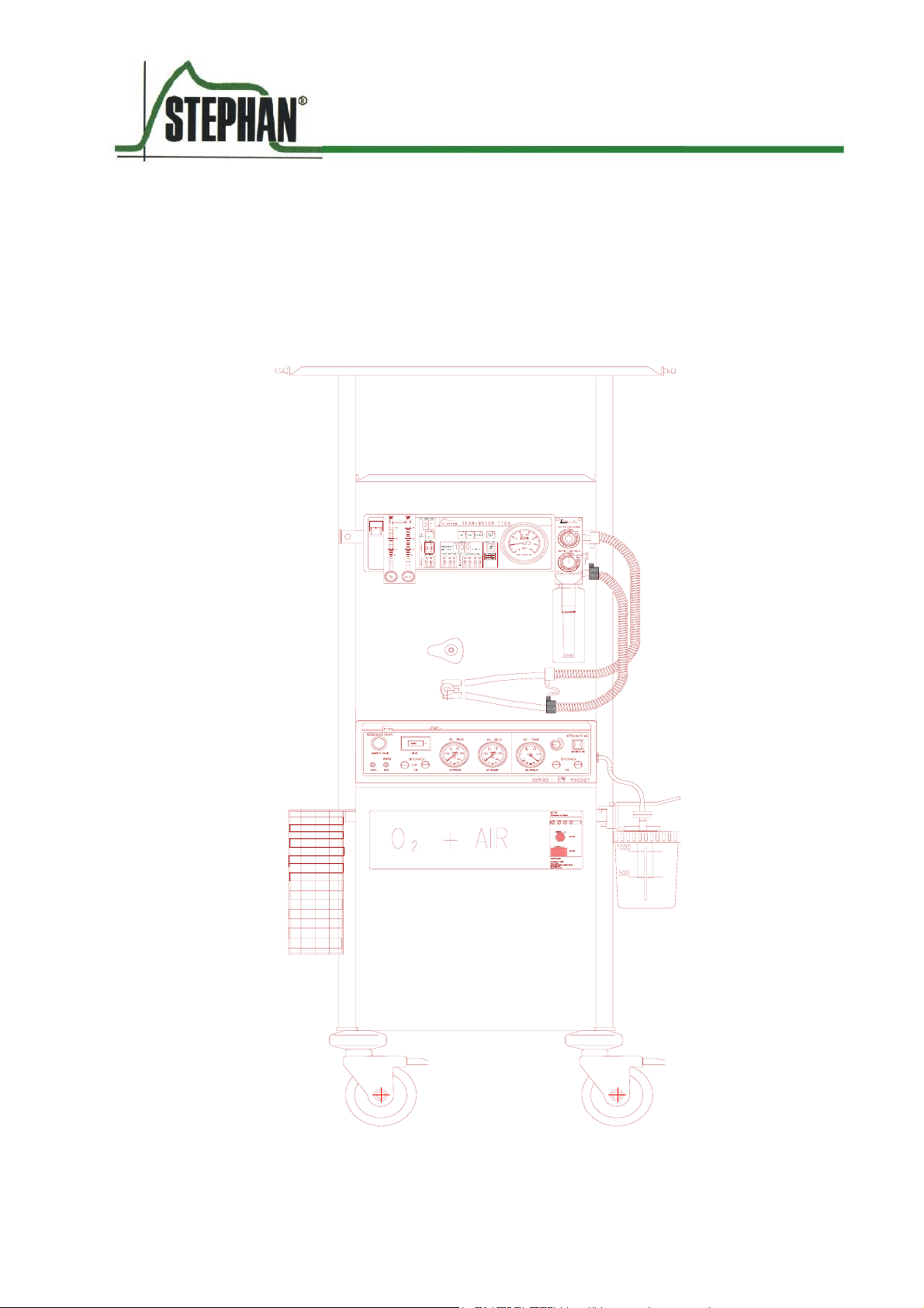
The STAXEL can be mounted on a service carriage and thus offers the greatest possible mobility
and flexibility.
It is made from stainless steel and therefore extremely resistant against weathering and easy to
keep in hygienic condition.
The STAXEL is available with a number of different shelves, brackets for appliances and
appliances rails for attaching instruments, holding devices or vessels.
Furthermore, four earthed sockets (Schuko) (230 V) are provided on the rear panel, where diverse
other appliances can be connected.
3
Page 5
STAXEL O2 and AIR Service Manual
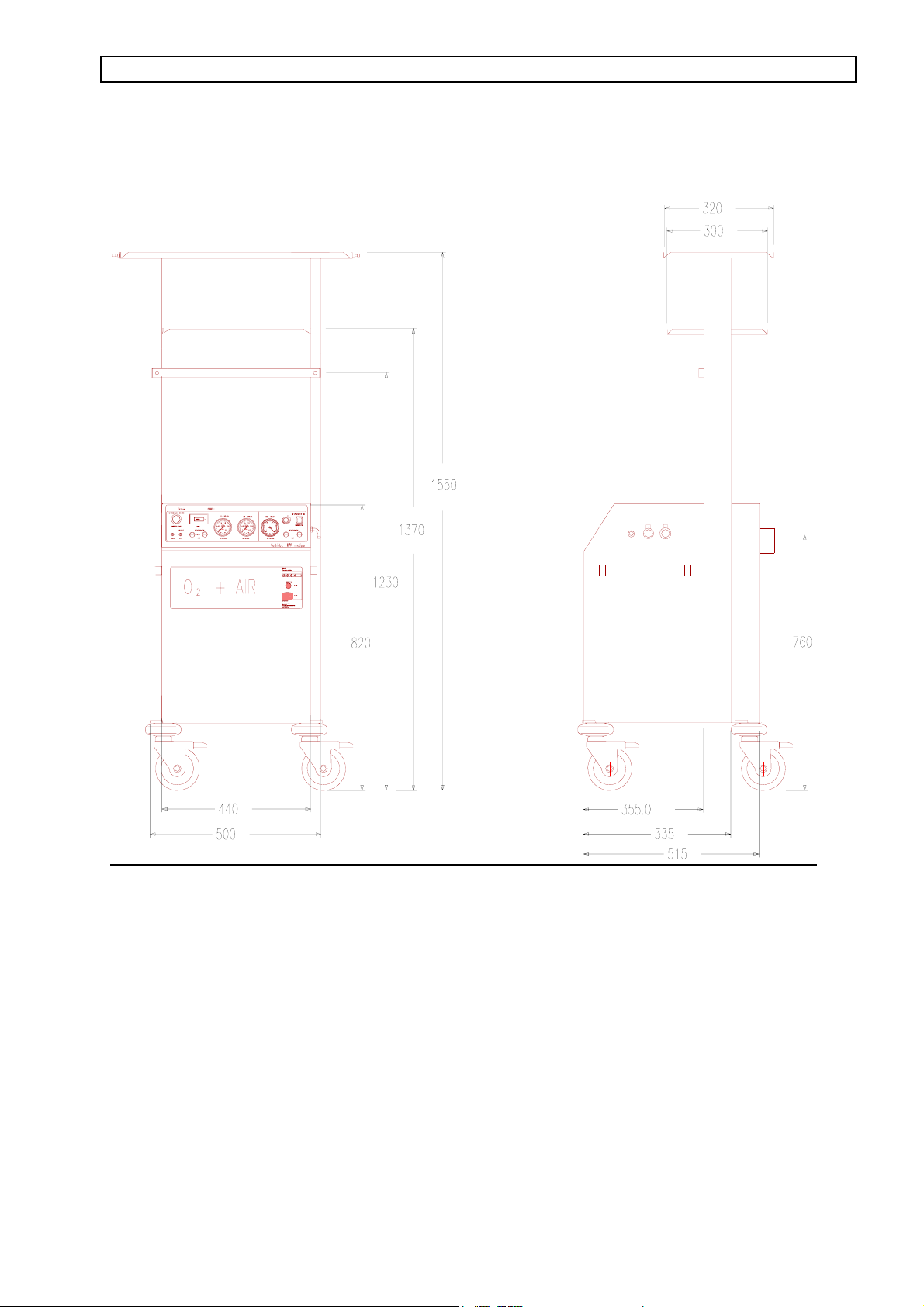
2. Technical dimensions
Modul für Intensiv-Therapie
BETIEBSTUNDENZÄHLER
LÜFTER
VAC O2 AIR
RÜCKWAND
4
Page 6

STAXEL O2 and AIR Service Manual
3. Construction and description of performance
3.1 Production of oxygen
The production of oxygen is based upon the adsorption effect of molecular sieves. For this
purpose, air which has been compressed by compressors is blown through two containers, which
are filled with molecular sieves.
Since the molecules of oxygen are smaller than these of nitrogen, the oxygen can pass the sieve
unimpeded, whereas the nitrogen is aborbed completely by the molecular sieve. Thus, air enriched
with oxygen is obtained at the outlet of the container.
Concentration of oxygen is approximately 95 % ( with an extraction of 5 litres / min). The
remaining 5 % are inert gases contained in the normal ambient atmosphere like argon, neon,
xenon etc.
Of the two containers filled with molecular sieves, only one at a time takes part in the production
of oxygen.
Prior to the first container being completely saturated with nitrogen, changeover to the second
container, which now performs the enrichment of air with oxygen, takes place.
While the second container is in operation, the first one is cleaned, using a portion of the produced
oxygen and can continue with the enrichment with oxygen, when the second container is saturated
with nitrogen. This process is cyclic and continuous.
3.2 Production of compressed air
Compressed air is produced by means of the two compressors, which also compress the ambient
air required for the production of oxygen. The compressed air is collected in a compressed air
reservoir and is now available for the production of oxygen as well as for use as medicinal
compressed air. The ambient air is hereby conducted through an intake filter and a bacteria filter
and then compressed in the compressors, which both operate free of oil. Thus the production of
compressed air always runs in parallel with the production of oxygen. The moment the STAXEL
is switched on , it produces compressed air as well as oxygen.
5
Page 7

STAXEL O2 and AIR Service Manual
3.3 Generation of vacuum
Vacuum is generated by means of a vacuum pump, which is additionally installed in the
STAXEL.
In parallel to the production of O2 and AIR, this vacuum pump can be switched on and off
separately. Vacuum pressure is infinitely adjustable from – 0,1 to – 0,6 bar by means of a rotary
knob.
3.4 Construction
The entire supply module is mounted in a sound-insulated twofold-steel housing, all rotating
components, like compressor or fans are mounted oscillation-attenuated. The escaping exhaust air
is evacuated via a noise-reducing filter.
The front panel of the appliance contains the displays of operating pressure for O2, AIR and VAC
as well as a hours-run-meter to indicate the scheduled intervals for maintenance and servicing
(exchange of filters etc).
The entire module is mounted onto a sturdy undercarriage with an appropriate holding rail, so that
all STEPHAN respirators as well as reanimators (pediatrics respirator F 150 and HF 300 SIMV)
can be used. The respirators can easily be detached from the unit and attached to a wall rail system
or to the incubator.
Attention:
The unit must not be operated without micro filter !!
6
Page 8

STAXEL O2 and AIR Service Manual
4. Installation and startup
4.1 Environmental conditions
The STEPHAN S T A X E L is intended for installation in dry rooms without risk of splash
water or water drops. Humid or wet environment can seriously impair the reliability of the unit.
Special care has to be taken to avoid placing containers filled with water or similar objects in the
near vicinity.
The ambient temperature should in no case exceed+ 40° C.
With a prevailing relative air humidity it is recommended to operate the unit only in air-
conditioned rooms.
The air – intake grids at the rear of the unit must not be covered or obstructed with any objects.
Distance from the rear of the unit to the wall should be at least 10 cm.
The STAXEL must not be operated in rooms, where an explosion hazard exists !!
The STAXEL must not be operated in the vicinity of open fire or red hot objects because of the
increased explosion hazard, which exists on account of the ambient air being enriched with
oxygen of high purity.
7
Page 9

STAXEL O2 and AIR Service Manual
4.2 Startup
First the STAXEL is connected to the mains supply (socket).
The STAXEL has two mains switches, one mains switch for the production of O2 and AIR and a
second one for the generation of vacuum.
By means of the mains switch ′O2 and AIR′ the unit is switched ON and OFF for the production
of oxygen and compressed air.
Immediately after switching it on, the „STAXEL“ starts to produce oxygen and compressed air.
The respective pressure gauges on the front panel, blue for oxygen and yellow for compressed air,
indicate the pressure at the respective outlets.
The typical values for oxygen and compressed air are 1 bar.
By means of the mains switch ′VAC′ the unit is switched ON and OFF for the generation of
vacuum.
Immediately after switching it on, the „Staxel“ starts to generate vacuum.
The pressure gauge at the front panel, white for vacuum, indicates the pressure at the respective
outlet.
The typical value for vacuum is – 0,5 bar.
On both sides of the unit one connection each for oxygen and compressed air is provided.
An additional connection for vacuum is provided on the right side of the unit.
During normal operation always one pair of connections ( O2 and AIR ) is used. If necessary, the
„spare pair of connections“ can be used in parallel for connecting a second respirator or incubator.
8
Page 10
STAXEL O2 and AIR Service Manual
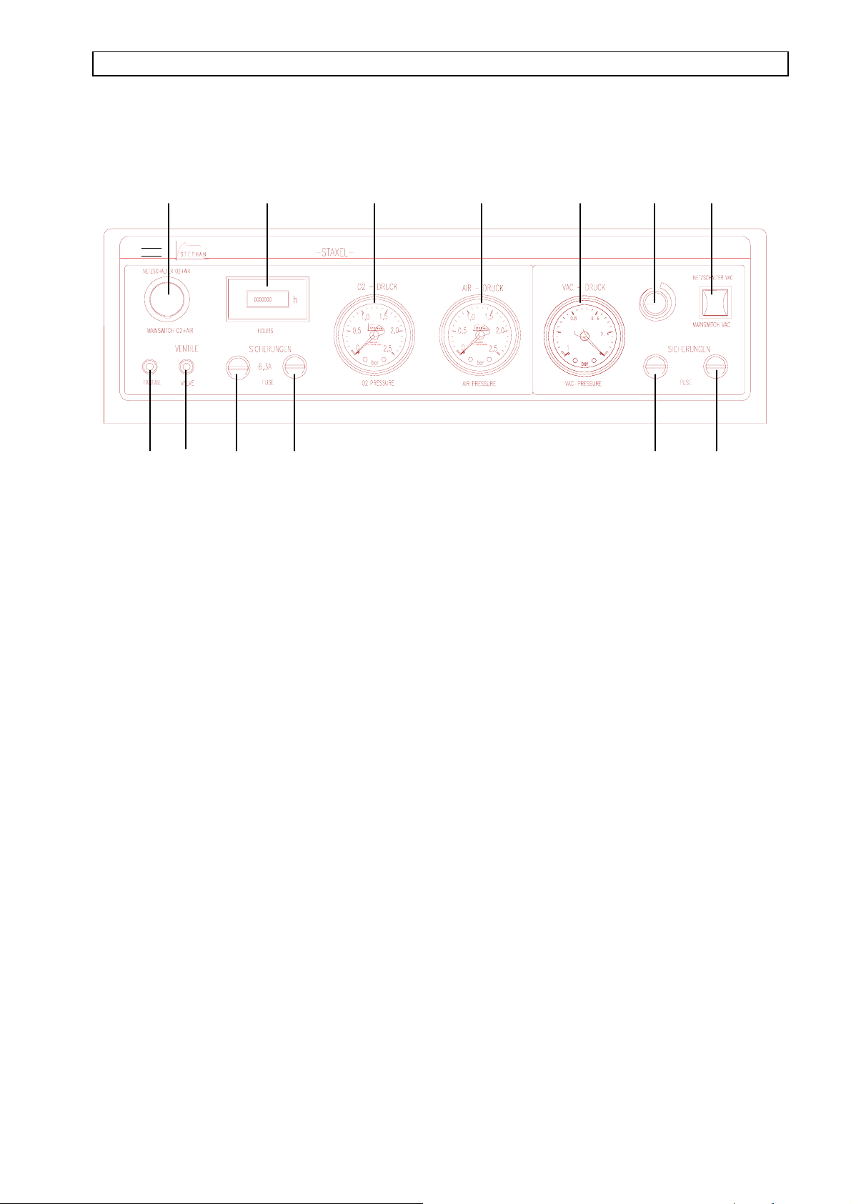
5. Control – and display elements
MWZ
L▄FTER
1
Modul f³r Intensiv-Therapie
1.1 1.2 1.3
BETIEBSTUNDENZ─HLER
1.4 1.5 1.6 1.7
1 Mains switch ON / OFF for O2 and AIR
1.1 Hours – run – meter for the production of O2 and AIR
1.2 Pressure gauge for indication of O2 – pressure
22.12.2
2.3 2.4
1.3 Pressure gauge for indication of AIR – pressure
1.4 Visual alarm for over – heating
1.5 Visual alarm for failure of electronics or switching valves
1.6 Fuse for O2 - and AIR – production
1.7 Fuse for O2 – and AIR – production
2 Mains switch ON / OFF for VAC
2.1 Rotary knob for regulating the vacuum pressure
2.2 Pressure gauge for indication of vacuum pressure
2.3 Fuse for generation of VAC
2.4 Fuse for generation of VAC
9
Page 11
STAXEL O2 and AIR Service Manual
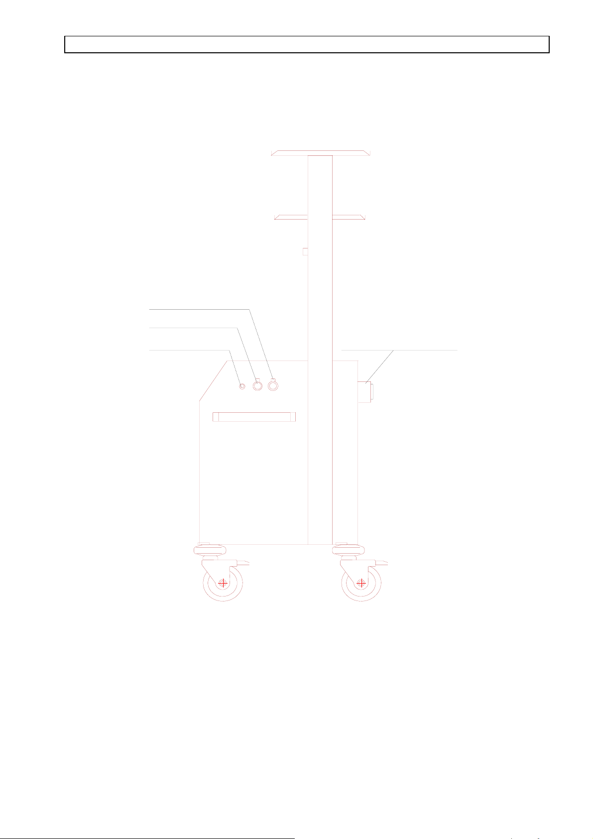
6. Connections for oxygen, compressed air and vacuum
Outlet compressed air
Outlet oxygen
Outlet vacuum
VAC O2 AIR
Strip of sockets with connecting cable
Outlets for O2 and AIR are located on both sides of the STAXEL. The connections are quick-
coupling and are are interlocked automatically after plugging in. To unplug them, the unlocking
pin on the top of the connection must be depressed.
The outlet for vacuum is located at the right side. The connection consists of a 1/8“ female hose
connector. The hose leading to the suction unit is slipped on.
10
Page 12

STAXEL O2 and AIR Service Manual
7. Technical description
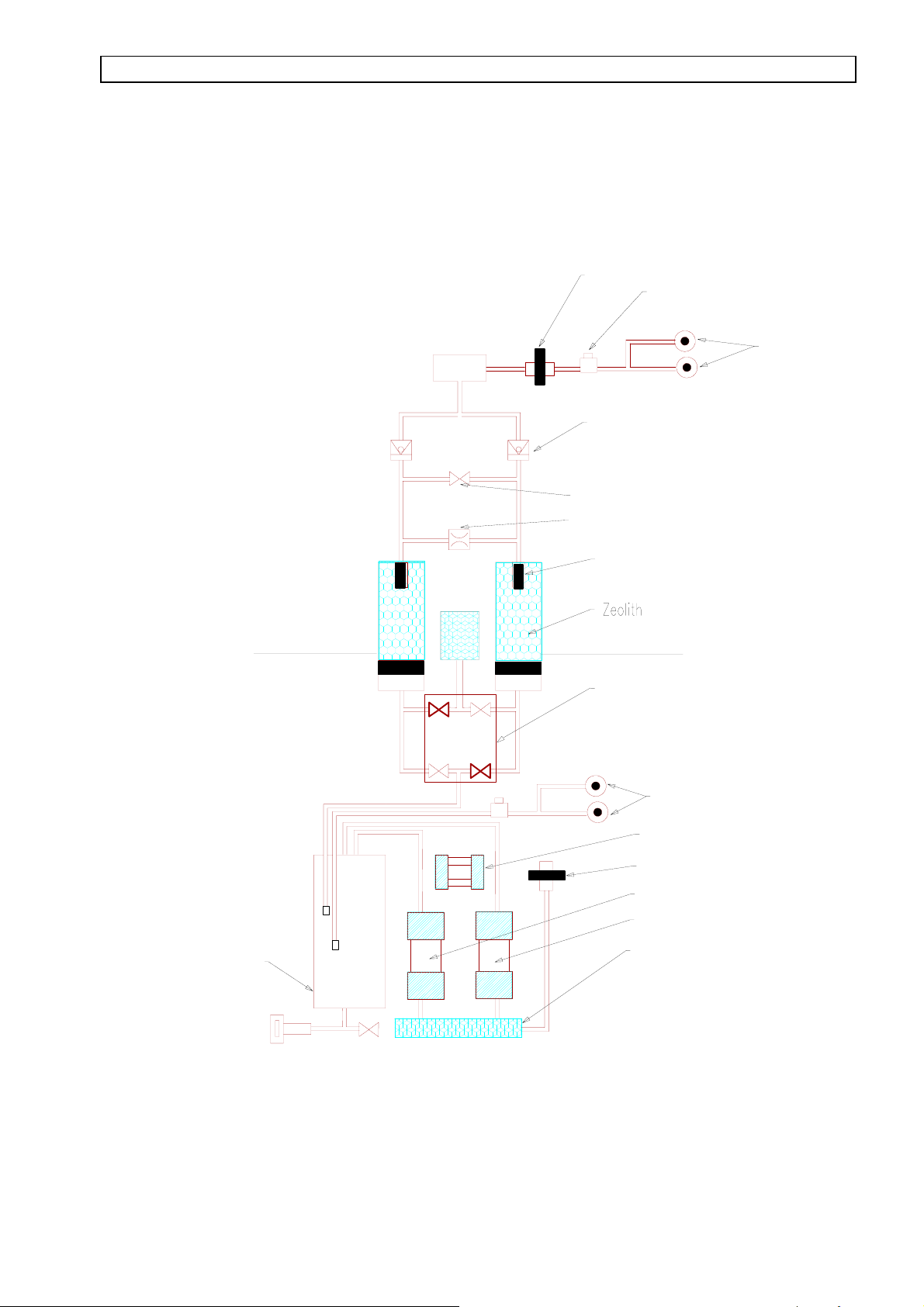
7.1 Description of system
Ambient air is taken in via a microfilter, led through a silencer inlet and finally compressed in the
compressors 1 + 2. The compressed air is then conducted over a condenser and cooled, before it
is collected in a pressure compensation reservoir. This reservoir is provided with an exhaust valve
for condensate water, which briefly opens every 45 minutes and blows the condensate water out.
The compressed air reservoir is continuously filled with compressed air from the compressors.
The AIR - outlets are supplied with compressed air from this reservoir. The output pressure is
limited to 1 bar by means of a pressure reducing valve. The compressors operate free of oil, thus
the provided air is medicinal compressed air.
The compressed air from the pressure compensation reservoir also supplies the two adsorber
containers A + B via a valve unit. The valve unit consists of a 5 / 2 – way valve, which is
electronically controlled. The valve is constructed in such a way, that only one adsorber at a time
takes part in the production of oxygen, while the other one is being scavenged and cleaned.
The compressed air is conducted through the adsorber containers.
The adsorber containers are filled with a special granulate, which works like a molecular sieve.
On account of the different sizes of molecules, the nitrogen contained in the air is physically
adsorbed, while oxygen and portions of inert gases are not adsorbed and form the residual gas
atmosphere, which is led into an O2 – resrevoir.
Through a nozzle and a scavenging valve, which are located at the outlet of the adsorber
containers, the adsorber not participating in the production of oxygen at this moment is blown
through with a portion of the produced oxygen and the nitrogen is flushed into the atmosphere.
This procedure is periodically repeated, whereby two adsorber containers are used alternatingly to
increase efficiency. The two adsorber containers are interlocked against one another via two back
pressure valves so that in the course of changing over to the adsorber container, which participates
in the production of oxygen the produced oxygen is not completely blown through the adsorber
container that has to be cleaned, but flows into the O2 – resrevoir.
The O2-outlets are supplied with oxygen from the reservoir via an additional microfilter. Pressure
at the outlet is limited to 1 bar by means of a pressure reducer.
11
Page 13
STAXEL O2 and AIR Service Manual
7.2 Schematic representation
Microfilter
Pressure reducer
Absorber A
O2 reservoir
GerõuschDõmpfer
Ausla▀
O2 outlet
Back pressure valve
Scavenging valve
Nozzle
Sintered filter
Absorber B
Valve unit
Pressure compensating
reservoir
Exhaust valve for
condensate water
AIR outlet
Fan
Microfilter
compressor 1
compressor 2
Silencer intake
12
Page 14

STAXEL O2 and AIR Service Manual
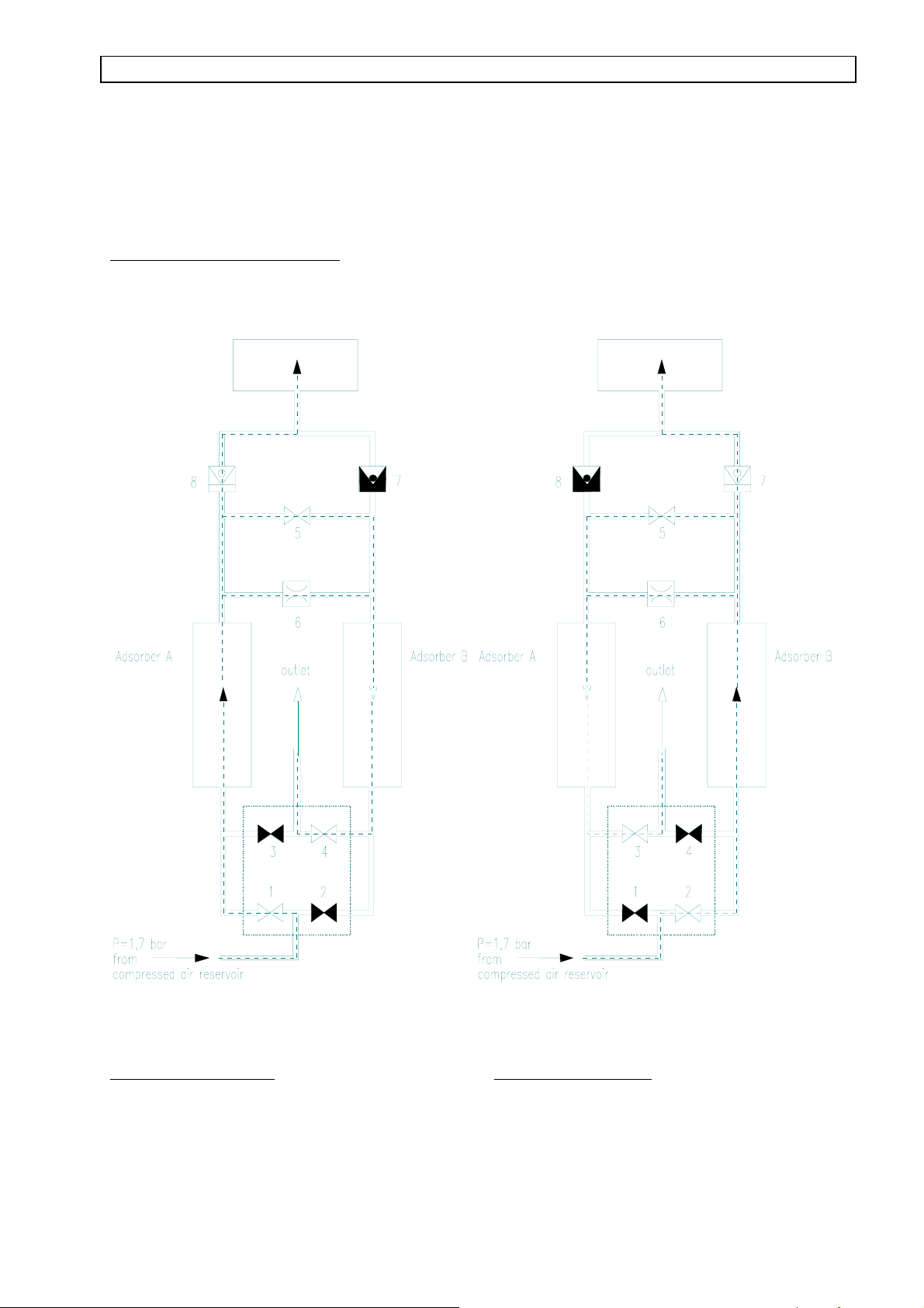
7.3 Switching attitude of the valve unit
Switching position A:
Medicinal compressed air of 1,7 bar from the pressure compensation reservoir is available at the
valve unit.
In switching position A the valves 1 + 4 are open. Through valve 1 flows compressed air through
the adsorber container A. The molecular sieve adsorbs the nitrogen part of the compressed air. The
residual gas atmosphere, consisting of oxgen and portions of inert gases is conducted into the O2-
reservoir via the back pressure valve 8.
A small part of the produced oxygen is conducted through a nozzle 6 to the adsorber B. The
oxygen, whose speed of flow is accelerated by the nozzle, now flows through the adsorber B,
scavenges the adsorbed nitrogen and flows to the outlet via the open valve 4.
One second ahead of the changeover from adsorber A to adsorber B, the savenging valve 5 opens
for the duration of two seconds and provides for the adsorber B to be scavenged once again with a
large portion of oxygen. After a cycle of 13 seconds the changeover from adsorber A to adsorber
B takes place.
Switching position B
Medicinal compressed air of 1,7 bar from the pressure compensation reservoir is available at the
valve unit
In switching position B the valves 2 + 3 are open. Through valve 2 flows compressed air through
the adsorber container B. The molecular sieve adsorbs the nitrogen part of the compressed air. The
residual gas atmosphere, consisting of oxygen and portions of inert gases is conducted into the
O2-reservoir via the back pressure valve 7.
A small part of the produced oxygen is conducted through a nozzle 6 to the adsorber A. The
oxygen, whose speed of flow is accelerated by the nozzle, now flows through the adsorber A ,
scavenges the adsorbed nitrogen and flows to the outlet via the open valve 3.
One second ahead of the changeover from adsorber B to adsorber A the scavenging valve 5 opens
for the duration of two seconds and provides for adsorber A to be scavenged once again with a
large portion of oxygen. After a cycle of 13 seconds the changeover from adsorber B to adsorber
A takes place.
13
Page 15
STAXEL O2 and AIR Service Manual
The changeover between adsorber A and B takes place cyclic and continuously.
All the switching times are a fixed program in the control electronics of the STAXEL and can not
be altered. Switching cycles can be checked by means of the LEDs on the control board.
Valve control O2 – separation:
O2 reservoir
O2 reservoir
Switching position A Switching position B
14
Page 16

STAXEL O2 and AIR Service Manual
8. Technical details
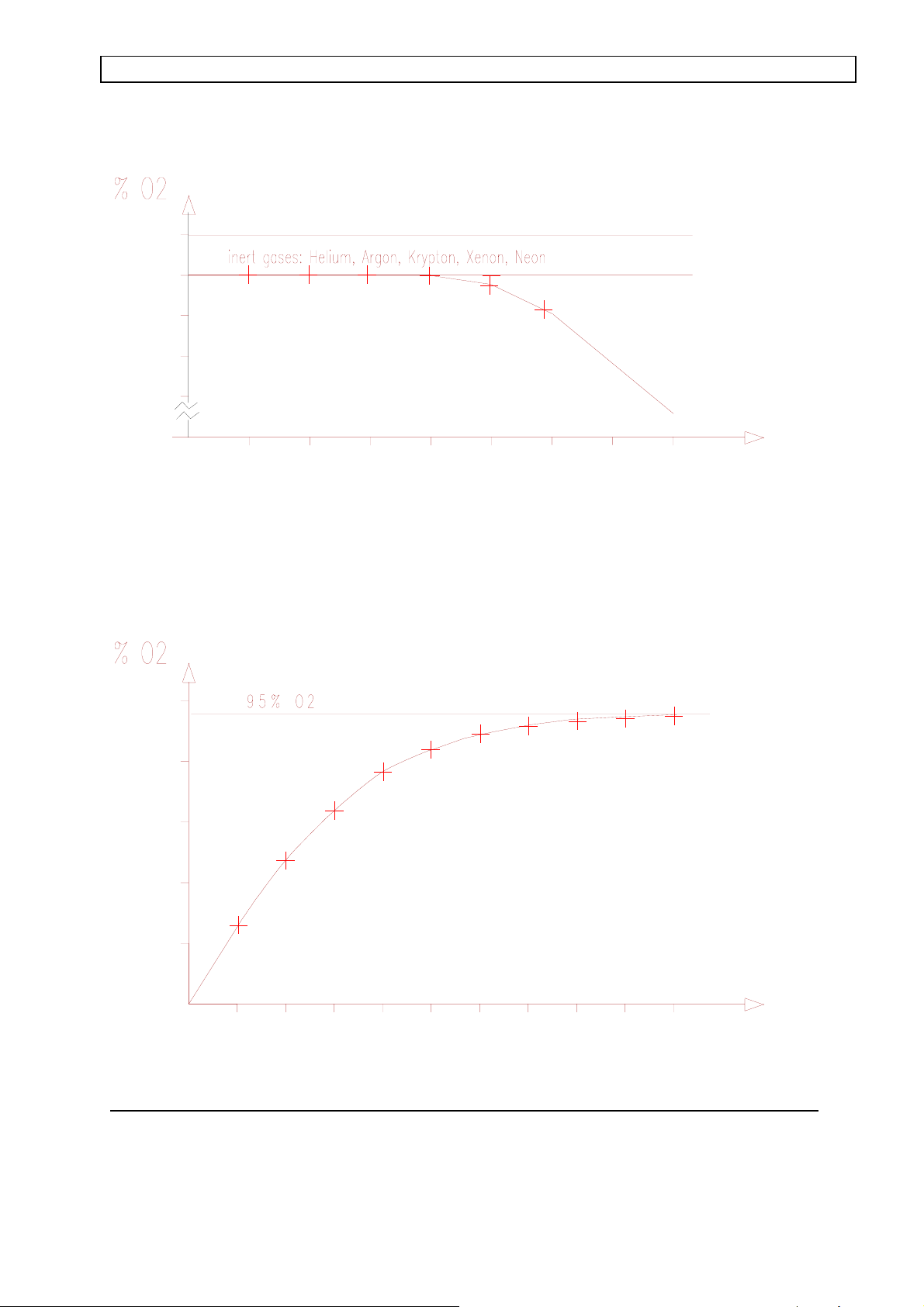
Available concentrations of oxygen with respective flow
Flow ( l / min ) O2 – concentration ( in % )
1 95
2 95
3 95
4 95
5 94
6 91
The values apply with a temperature of 25° C and a relative air humidity of 60 %.
Furthermore, concentration of O2 fluctuates for + / - 2 %
Specifications
Supply voltage 230V / 50Hz
Current consumption 5 A
Changeover cycle 13 sec
Duration of one scavenging 2 sec
Noise level 48 dB ( A )
Dimensions ( L x W x H ) 500 x 510 1550
Weight ca. 65 kg
Compressor
Number of revolutions 1380 R/min
Power consumption 2 x 250 watt
Capacitor 2 x 8 µF / 400 V
Fan::
Number of revolutions: 930 R/min
Power consumption 1 x 80 watt
Capacitor 2 µF / 400 V
15
Page 17
STAXEL O2 and AIR Service Manual
n
9. Performance data of STAXEL
100
95
90
85
80
100
80
60
40
12345678
Production of oxygen dependent on consumed quantity
l / min
20
12345678910
t [ min ]
Produktion of oxygen dependent on time, with consumption of ca 6 litres/mi
16
Page 18

STAXEL O2 and AIR Service Manual
10. Error detection system
Error Cause Elimination
No pressure at O2 and
compressed air,
audible alarm
Initial pressure of O2 or
compressed air falls below 0,7
bar
audible alarm
Red LED (1.4 ) illuminates ,
Staxel is overheated
unit ceases to operate
Red LED (1.5) illuminates valves do not switch properly
Failure of supply voltage
fuse defective
Microfilter is obstructed
Consumption of gas is too high
Compressor defective
Leak in line
Airflow is too weak Exchange filter mat
Electronics defective
Compressors defective
Check supply voltage
Exchange fuse
Exchange microfilter
Reduce consumption of gas
notify service agency
check fan for sufficient
performance
(exchange if necessary
Notify service agency
Concentration of O2 falls
below minimum value
Supply hose torn off
Pressure between the two
adsorber containers is no longer
balanced, obsolete adsorber
containers
Adsorbers must be adjusted
anew
adsorber containers must be
exchanged
17
Page 19

STAXEL O2 and AIR Service Manual
11. Maintenance
Maintenance
The Stephan STAXEL requires only little maintenance.
For hygienic reasons the unit should be cleaned periodically by wiping it, using customary
household cleansing agents or disinfectants ( e.g Sagrotan, diluted ).
The microfilter and the filter mat must be exchanged every 10 days or after each 240 hours run.
12. Guarantee
If used according to instructions, the product is guaranteed for 12 months from the date of sale.
The guarantee applies to replacement and repair of parts, for which a fault in material and
manufacturing can be acknowledged.
18
Page 20

STAXEL O2 and AIR Service Manual
13. Service
To warrant faultless performance, the units must be checked after each approximate 1000 hours
run, at least, however, once a year, by an authorized specialist firm. Eventually occurring
disorders or failures must only be eliminated by the service department. After 10.000 hours run, a
general overhaul has to be carried out by the service department.
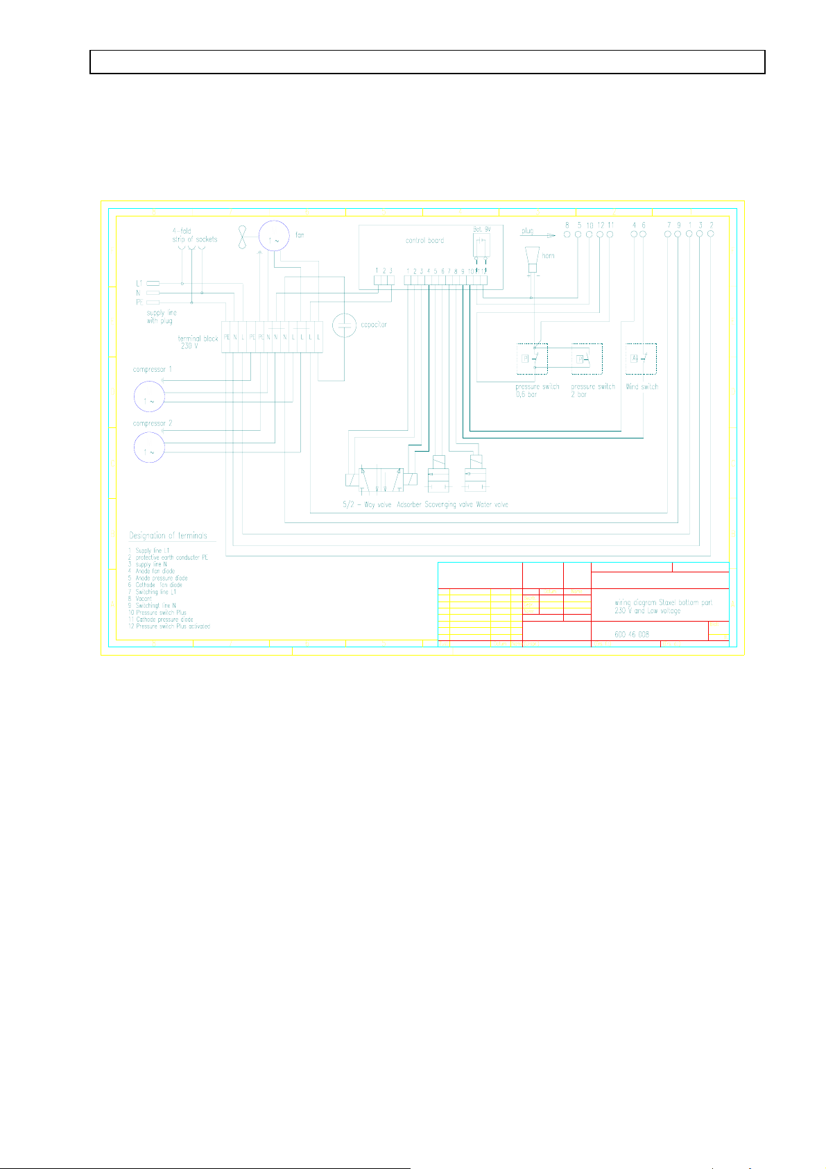
13.1 Power supply
The mains supply takes place by means of a connection cable, which is led into the strip of sockets
on the rear of the STAXEL. The terminal block (230 V) is connected with the strip of sockets by
means of an interconnecting cable. The mains supply L 1, N and PE is led from the terminal strip
to the mains switch ′O2 + AIR′ in the STAXEL – housing lid. ( Designation of terminals: 1,2,3).
The mains switch switches the mains supply bipolar on, resp.off. From the mains switch
′O2 + AIR′ the switched mains supply is led back to the terminal block (Designation of terminals:
7,9,). The terminal block (230 V) supplies the two compressors 1 + 2 , the fan, as well as the
control board with the switched mains supply.
On the control board the 230 V mains supply is transformed and converted to 5 V (DC) and 24 V
(DC).
The valves are activated with 24 V (DC). The pressure switches and the wind switch are supplied
with 5 V (DC). A 9 V – battery is connected in parallel to the 5 V – supply. This battery takes
over the voltage supply of the monitoring components ( pressure switch and horn) in case of
failure of mains supply.
The 5 V – supply is switched on and off by means of the mains switch O2 + AIR, (designation of
terminals10, 12) and then supplies the pressure switch. In case of failure, the pressure – LED in
the lid of the STAXEL is activated (designation of terminals 11, 5). In addition, the horn sounds.
The wind switch is supplied with a second 5 V – voltage, which is tapped directly from the control
board. In case of failure, the fan LED in the Staxel – lid is activated. (designation of terminal 4, 6).
Voltage supply (230 V) for the vacuum pump is tapped in parallel from the terminals 1 + 3 in the
STAXEL – lid. The vacuum pump is switched on, respectively off, directly by means of the mains
switch ′VAC′.
19
Page 21
STAXEL O2 and AIR Service Manual
13.2 Wiring diagram, STAXEL bottom part
M
M
M
Maßstab
Änderung
20
Page 22

STAXEL O2 and AIR Service Manual
g
b
13.3 Wiring diagram V2A – cover of STAXEL
Maßsta
Änderun
21
Page 23

STAXEL O2 and AIR Service Manual
13.4 Adjustment of the adsorber containers
To guarantee a faultless performance of the STAXEL, a check and in case a renewed calibration
of the pressure controllers on the O2-reservoir should be carried out with each servicing. In
addition, the adsorber containers must be checked.
Checks:
Pressure controller of O2 reservoir
The two pressure controllers for minimum and maximum pressure on the O2-reservoir must
release an alarm with the following values:
limit for minimum pressure: 0,6 bar
limit for maximum pressure 2 bar
- all tubes and copper tubes must be checked for leaks
- coarse filters and microfilters must be exchanged if necessary
-
-
faultless performance of the solenoid valves must be checked
the filter mat at the intake grid of the blower must be exchanged if necessary.
22
Page 24

STAXEL O2 and AIR Service Manual
Adsorber container
To guarantee maximum concentration of O2, calibration must be carried out as follows:
- pressure gauges must be installed as shown in figure 1
- hereafter, the STAXEL must run for 10 minutes under operating conditions
- a flow of 6 l/min is set on tbe O2-connection, a flow of 5 l/min is set on the
compressed-air-connection
- pressure displayed by the pressure gauges should be 0,1 bar on the exhausted adsorber
and must rise to approximately 1,5 bar, when the adsorber is filled again.
Attention: If pressure with exhausted adsorber does not fall below 0,2 bar, the outlet
filter must be exchanged ( see 13.5.6 ) !
- deflections of the pressure gauges on both adsorber containers must take place
simultaneously and in contrary direction.
- concentration of O2 should now have a value of not below 90 %
23
Page 25

STAXEL O2 and AIR Service Manual
Supplement for the adjustment of the adsorber containers
Figure 1
24
Page 26
STAXEL O2 and AIR Service Manual
13.5 Technical details
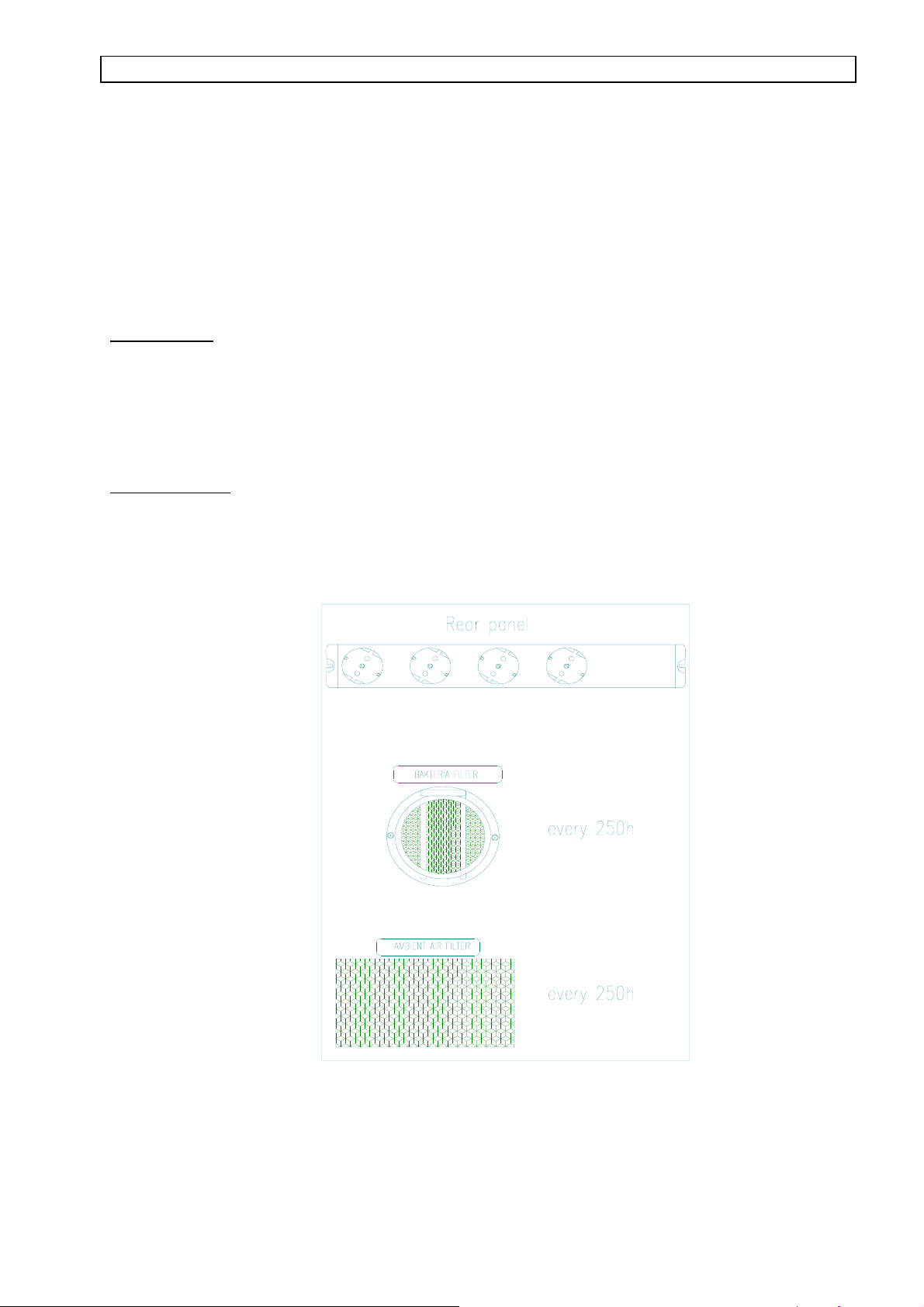
13.5.1 Exchanging the bacteria filter and the intake filter mat (ambient air filter)
Bacteria filter
The bacteria filter is located at the rear of the STAXEL. The retaining clip is pulled
upward and out, the old filter set is removed and the new set is inserted. Hereafter the
retainig clip is replaced.
Intake filter mat
The intake filter mat (ambient air filter) is located at the rear of the STAXEL. The old filter
mat is pulled out of the fixture and the new filter mat is inserted.
25
Page 27

STAXEL O2 and AIR Service Manual
13.5.2. Removing the top part, the rear panel and the side covers
Top part
-unscrew the holding screws
-lift the top part
-disconnect the electrical connections on the plug
-pull off tubes from the pressure gauges
Rear panel
-unscrew the holding screw
-detach rear panel until the intake tube slides out of its mounting
-disconnect the electrical connection at the terminal block
Side cover
-remove top part and rear panel
-unscrew and remove the square tubes of the assembly elements
-unscrew the remaining screws at the lower rim
-detach side covers so far, that the connections with the outlets for O2 and AIR
can be disconnected
-pull the complete side cover forward and out and remove it.
26
Page 28

STAXEL O2 and AIR Service Manual
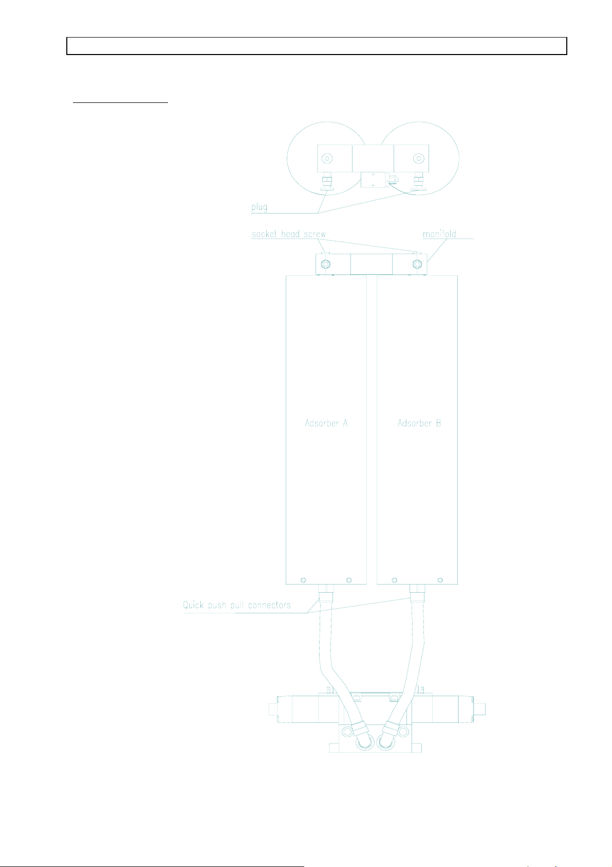
13.5.3 Removing the adsorber containers
-remove top part and rear panel
-unscrew the two socket head screws on the adsorber manifold and remove the -
manifold
-undo the two holding straps on the adsorber containers
-last disconnect the quick push-pull connectors at the bottom of the adsorber
containers
-remove the adsorber containers
Important:
Always close the removed adsorber containers airtight, because otherwise the
granulate (molecular sieve) will be destroyed.
ATTENTION !!
Do not attempt to disassemble the adsorber containers. The filling material of the adsorbers
is compressed by means of a spring with a spring rate of 450 N !
Adsorber containers must always be exchanged completely.
27
Page 29
STAXEL O2 and AIR Service Manual
Adsorber container
28
Page 30

STAXEL O2 and AIR Service Manual
13.5.4. Removing the compressed-air-reservoir
• remove STAXEL top part and rear panel
• unscrew brass screw coupling on the copper tube
• pull PVC tubes on top out of the quick push-pull connector
• undo holding straps
• pull exhaust valve for condensate water and excess pressure valve on the bottom out of the
quick push-pull connectors
• remove air reservoir
•
29
Page 31

STAXEL O2 and AIR Service Manual
13.5.5. Removing the compressors
-remove top part, rear panel and side covers
-unscrew the screws of the front panel on the compressor housing, remove front panel
-unscrew the screws of the cover on compressor housing
-disconnect the copper tube from compressed air reservoir
-undo and remove hose clamp of fabric tube on the cooler
-remove socket strip from the control board
-disconnect all electrical connections on the terminal block (note allocation of terminals)
-lift off cover of compressor housing complete with fan
-loosen fabric tubes on the compressors and remove them.
-unscrew mounting rails of compressor ( 4 X nut M5 )
-take compressors out
13.5.6. Exchanging the outlet filter
-remove top part, rear panel and side covers
-unscrew screws of the cover on compressor housing
-disconnect the copper tube from compressed air reservoir
-undo and remove hose clamp of fabric tube on the cooler
-remove socket strip from the control board
-disconnect all electrical connections on the terminal block (note allocation of terminals)
-lift off cover of compressor housing complete with fan
-unscrew and remove the old outlet filter from rear panel of compressor housing
-screw in new outlet filter
30
Page 32
STAXEL O2 and AIR Service Manual
14. STAXEL set of spare parts for an operating period of 2 years
Item Product number Designation No. of pieces
1 804 60 008 Fuses 6,3 A (slow-blow) 2
2 804 60 003 Fuses o,5 A (slow-blow 2
3 600 61 115 Bacteria filter set 15
4 600 61 123 Intake filter mat 10
5 811 60 010 Batteries S1 3
6 600 40 046 Sound absorber 3
Spare parts
Microfilter (bacteria filter), article no: 701 60 250 exchange after maximum 500 h
Intake filter mat article no: 701 60 205 clean weekly, respectively exchange
31
Page 33
STAXEL O2 and AIR Service Manual
15. Modules with product numbers
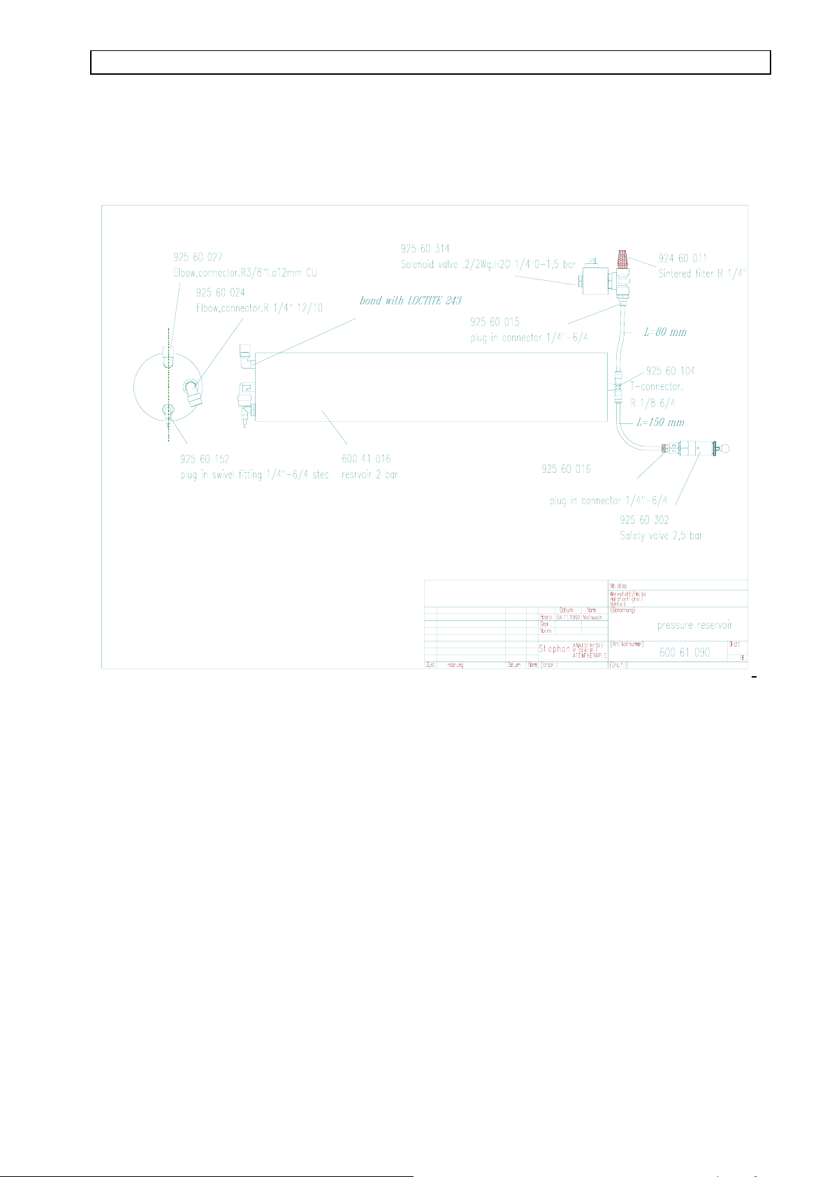
15.1 Pressure reservoir complete
ß
Ä
Ä
32
Page 34

STAXEL O2 and AIR Service Manual
15.1 O2 – reservoir, complete
ß
Ä
Ä
33
Page 35
STAXEL O2 and AIR Service Manual
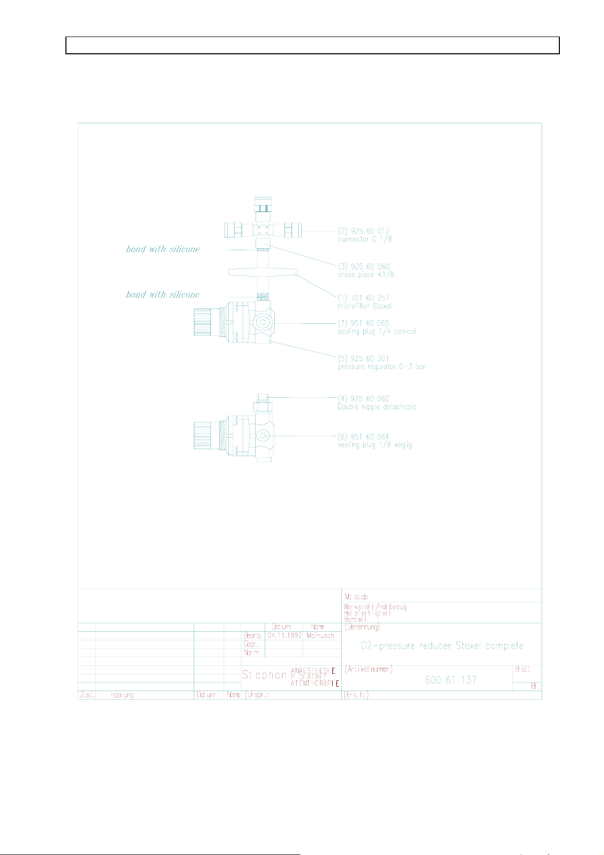
15.3. O2 pressure reducer STAXEL, complete
ß
Ä
Ä
34
Page 36

STAXEL O2 and AIR Service Manual
15.4 Terminal block STAXEL, bottom part
ß
Ä
Ä
35
Page 37

STAXEL O2 and AIR Service Manual
15.5 Cover STAXEL, bottom part
Kabeldurchf³hrung 15/6
L÷tnippel d=12,6 mm innen d=10 mm
Luftk³hler Staxel
Geblõse doppelflutig
Dõmm-Matte-Kompr.raum-Vent.
ß
Ä
Ä
36
Page 38

STAXEL O2 and AIR Service Manual
15.6 Housing lid STAXEL
Modul für Intensiv-Therapie
BETIEBSTUNDENZÄHLER
LÜFTER
ß
Ä
Ä
37
Page 39
STAXEL O2 and AIR Service Manual
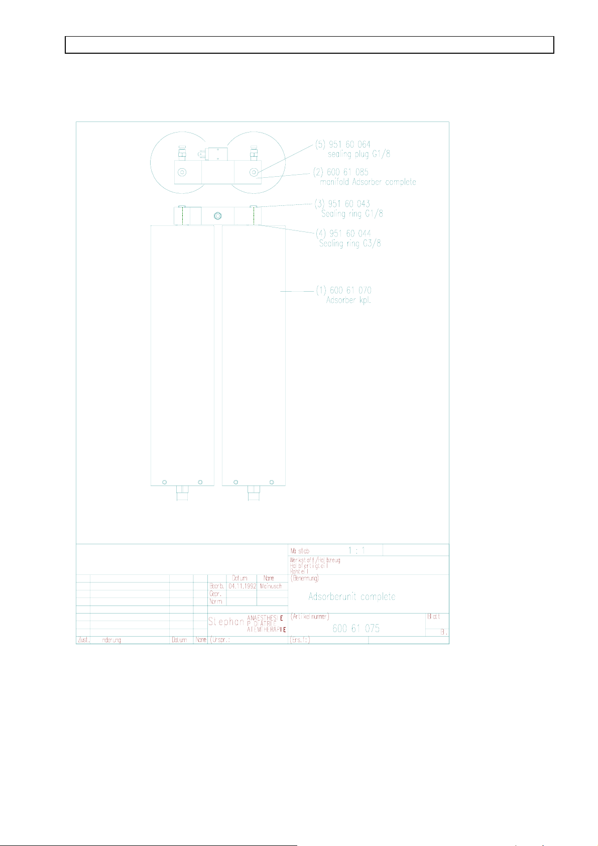
15.7. Adsorber unit, complete
ß
Ä
Ä
38
Page 40
STAXEL O2 and AIR Service Manual
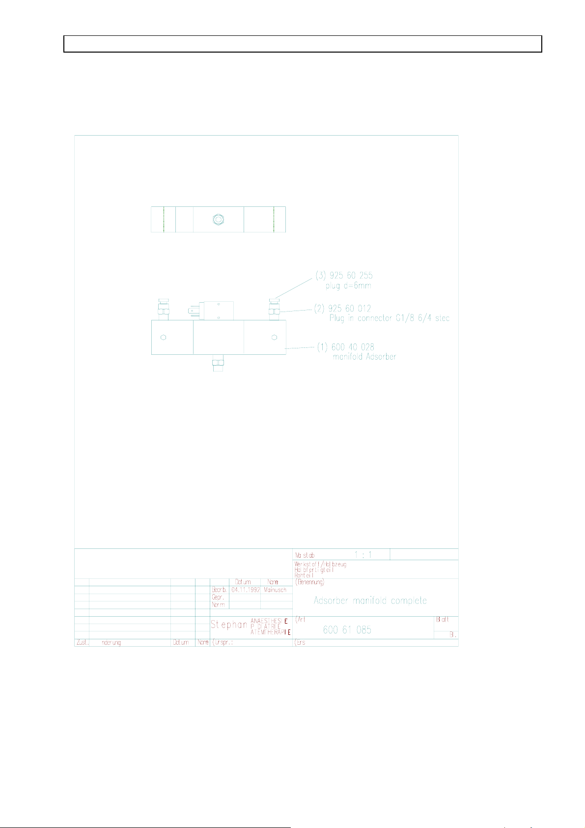
15.8. Adsorber manifold, complete
ß
Ä
Ä
39
Page 41
STAXEL O2 and AIR Service Manual
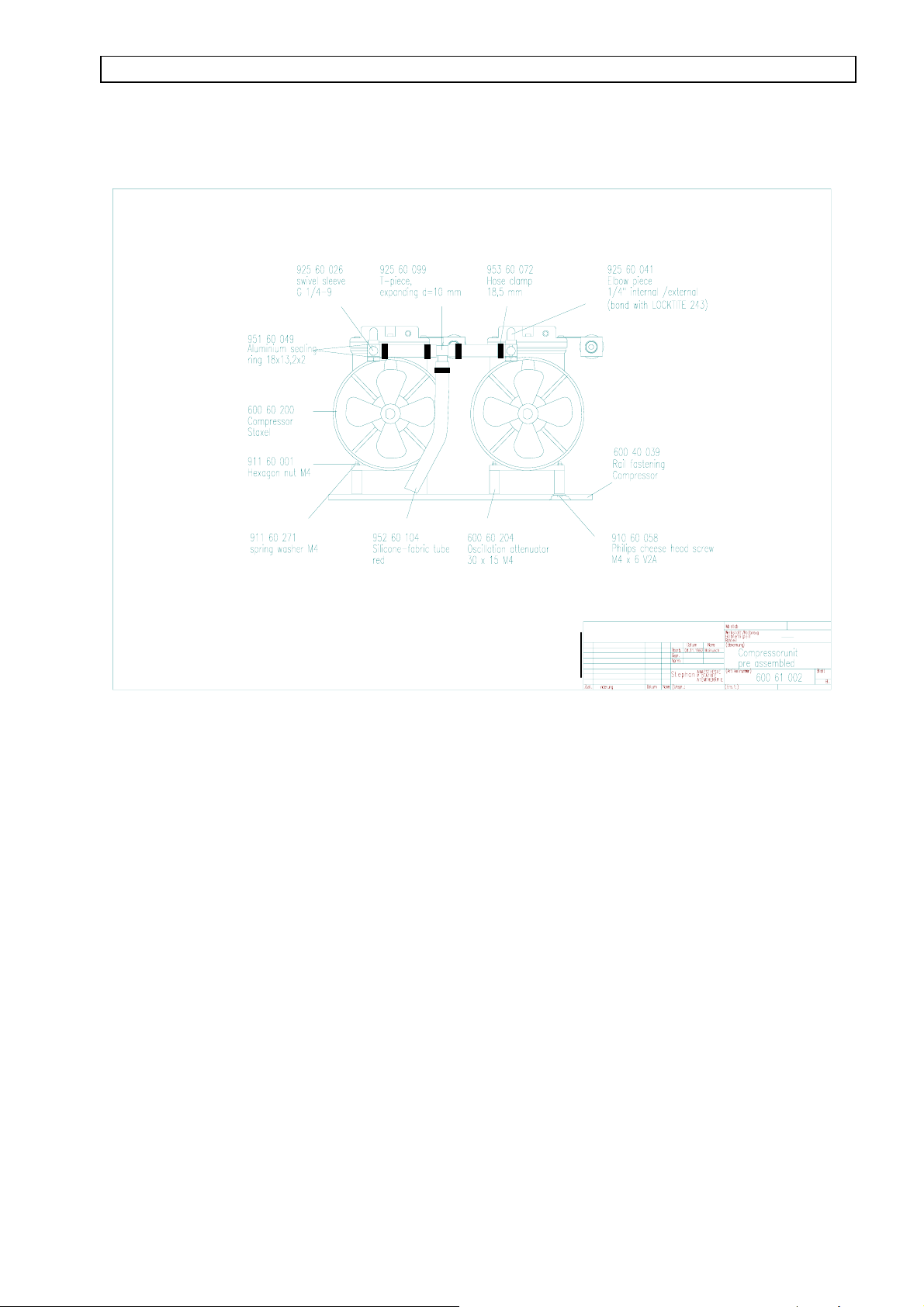
15.9 Compressor unit, pre-assembled
ß
Ä
Ä
40
 Loading...