

Page 1
EVE
Quick Guide
Page 2

Please read the detailed operating manual carefully.
The Quick Guide does not replace the operating manual.
Equipment is subject to technical modification
Valid as of: 04/2020
Version: V1.0
From Software version: 2.3
Artikel-Nr.: 107090078
Fritz Stephan GmbH Medizintechnik · Kirchstraße 19 · 56412 Gackenbach · Germany
Tel. +49 6439-91 25-0 · Fax +49 6439-91 25-111 · [email protected] · www.stephan-gmbh.com
Page 3
Design and functional description
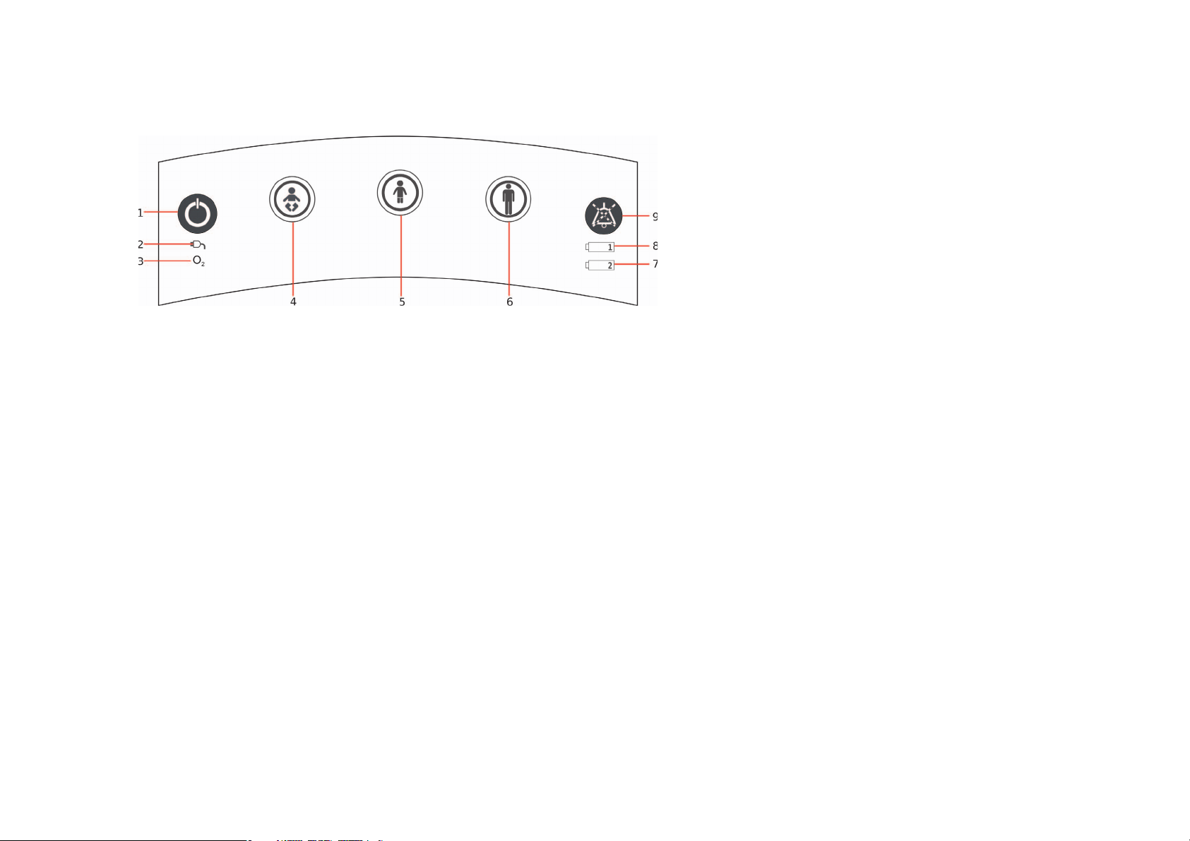
Control panel
1 On/O -Button
2 Mains power indicator
3 O
4 Fast tracking key „Preterm infants and
newborns“
5 Fast tracking key „Child“
6 Fast tracking key „Adult“
7 Charge indicator „Battery 2“
8 Charge indicator „Battery 1“
9 Acoustic alarm suppression
supply indicator
2
Page 4
Design and functional description
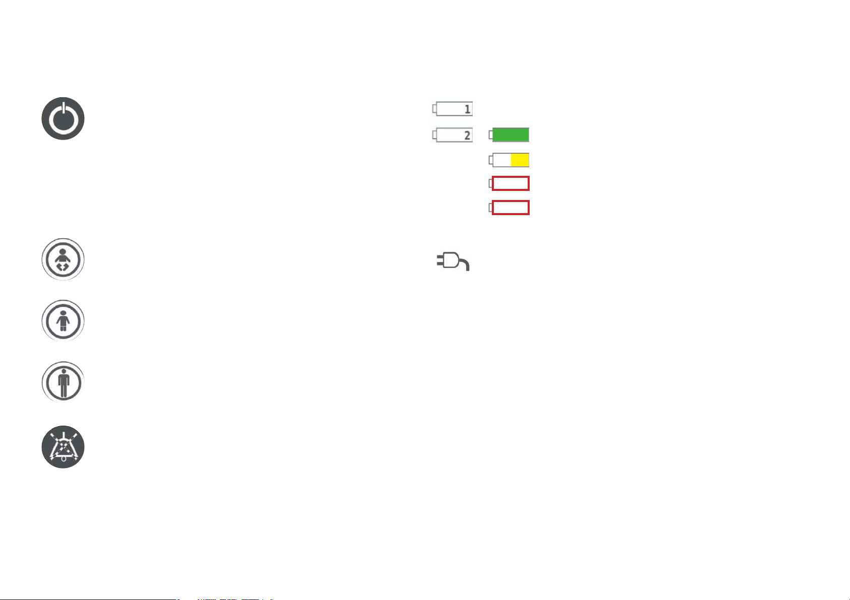
On/O /Standby-Button
Press this button to switch the EVE
on/o or, in the case of ongoing
ventilation, to switch it to Standby
mode.
Fast tracking keys
To prevent operator errors, the desired fast
tracking key must be pressed for 0.5 s,
a er which it starts to flash green.
Pressing the key again for 0.5 s will then
start or switch to the selected ventilation
mode.
Battery charge indicator
: Capacity: 75 - 100%
: Capacity: 40 - 75%
: Capacity: 1 - 39%
, flashing: 0% or Error
Mains power indicator
When connected to the energy
supply, the mains power indicator is
green. The internal batteries are
charged automatically as needed.
The battery charge indicators tell
you the current battery level.
Acoustic alarm suppression
If the key is pressed again within 5 s,
the alarm suppression is canceled.
Pressing the key again a er 5 s has
passed will start an new 2 minute
countdown.
O
Oxygen supply indicator
2
The indicator is green when an
oxygen source with su icient fill
pressure is connected.
Page 5
Design and functional description
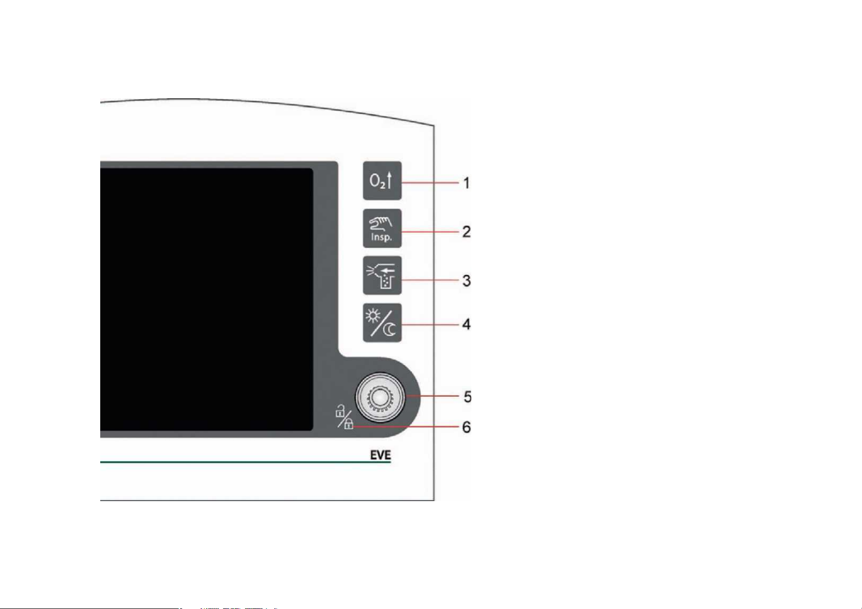
Function buttons
1 Button „Preoxy“
2 Button „Inspiration Hold“
3 Button „Aerosol“
4 Toggle button „Day/Night“
5 Control knob „IGR“
6 Lock/Unlock touchscreen
Page 6

Functional description
Button „Preoxy“
Press the „Preoxy“ button to administer
a pre-adjustable inspiratory oxygen
concentration for a certain preset
interval. These settings can be configured in the „System Settings/Function“
menu. At the same time, the display of
the set oxygen concentration changes
to the pre-set „preoxy“ value. The alarm
limits for oxygen concentration are
adjusted automatically. The button
is green while pre-oxygenation is in
progress.
Button „Inspiration Hold“
Pressing this button during inspiration
will hold inspiration at the end
of the normal inspiration phase for
the duration for which the button is
pressed (maximum 15 s). Pressing
the button during expiration will
trigger a mandatory inspiration using
the set ventilation parameters.
Button „Day/Night“ Toggle
This button lets you toggle the
display, alarm indicator and
patient/function buttons
between day and night mode.
Page 7

Functional description
Button „Aerosol“
Press the „Aerosol“ button to switch on
aerosol nebulization. The medication
nebulization duration can be set to
between 5 and 30 min in the „System
Settings/Function“ menu. The nebulization ends automatically at the end
of the set time or when the button is
pressed again. The button is green
while nebulization is in progress.
Aerosol nebulization is only possible if
O
is connected to the ventilator.
2
Lock/Unlock Touchscreen
Pressing the control knob for three
seconds will lock the touchscreen.
Press the control knob again for three
seconds to unlock the touchscreen.
When you tap the locked touchscreen,
a lock icon appears in the „System
Settings“ field.
Control knob „IGR“
Use the control knob to select and
activate all indirect functions.
The control knob has the following
functions:
• Switching within the menus
• Selecting and executing menu
functions
• Selecting and confirming parameter
settings
Page 8
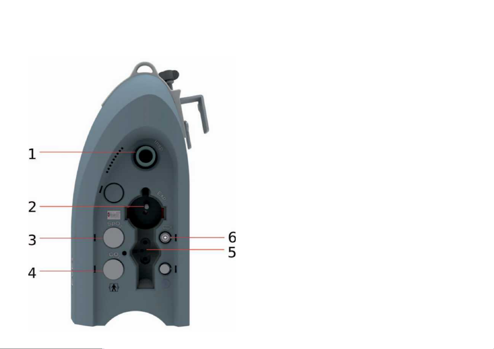
Design and functional description
Right side view
1 Connection Inspiration tube
2 Connection Exspiration tube
3 Connection SpO
4 Connection CO
Sensor
2
Sensor
2
5 Connection Flow Sensor
6 Connection Aerosol nebulizer
Page 9
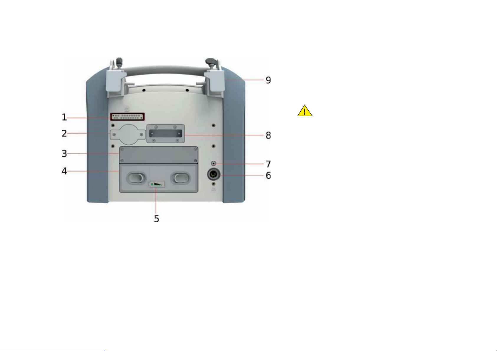
Design and functional description
Rear view
1 Docking station interface
2 O
Use only original Stephan O
Sensor cover
2
sensors
2
3 Internal battery 1
4 External battery 2 (optional)
5 External battery charge level indicator
Lets you check the battery even when the
device is switched o (LEDs).
6 Power supply input
7 Reset button
(no reset to factory settings)
8 Docking station bracket
9 Adjustable bracket
Page 10

Preparation for use
To connect the oxygen cylinder:
• Fit the oxygen cylinder to the bracket on the
mobile stand and secure.
• Connect the pressure regulator
• Connect the O
hose to the O2 input on the left
2
side of the EVE.
• Slowly open the valve and then slowly
release it completely.
Changing the oxygen cylinder
• Hand-tighten the valve on the gas cylinder
• Drain any residual gas from the pressure
regulator via the output until the pressure
gauge on the pressure regulator shows „0“.
• Loosen the O
the O
input
2
nist screw connector from
2
• Loosen the fastening buckles on the
support frame and carefully remove the
oxygen cylinder
• Remove the pressure regulator from the
valve by turning the screw connector
counter-clockwise and connect to the
Note safety instructions
new cylinder
• Place the new cylinder in the support
frame and close the fastening buckles
• Fit the O
O
input
2
nist screw connector to the
2
• Open the pressurized gas cylinder‘s valve
Page 11
Preparation for use
Connection to the central gas supply
If the device is not operated with an oxygen
source, it must be connected to the CGS.
Connect the O
hose to the O2 connector on the
2
left side of the EVE and to the CGS wall outlet.
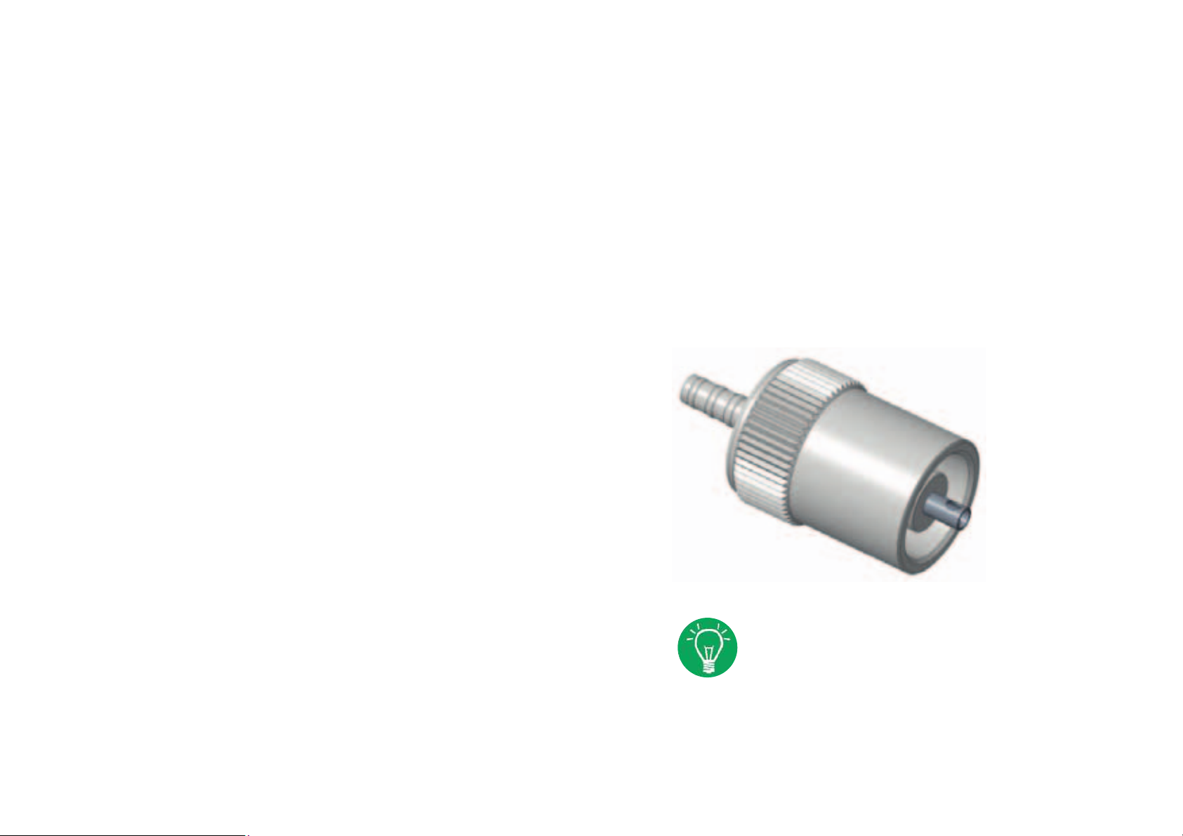
Connection to a low pressure
oxygen concentrator
When using oxygen with a concentration of
93% an adapter must be screwed on to EVE‘s
oxygen inlet and the „LPO“ option must be
activated.
„LPO“ adapter,
Art.-No. 107061187
The input flow must be at least
3 l/min. The Fio
setting on the
2
device is deactivated.
The oxygen concentration must be
set on the concentrator.
Page 12
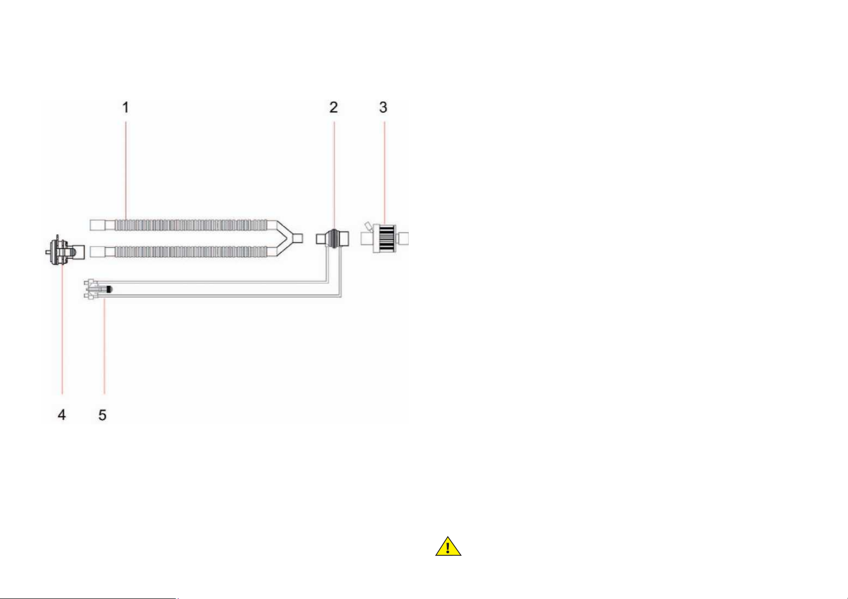
Connecting the patient tube system
ICU disposable tube system
1 Dual tube system
2 Flow sensor for adults
3 Patient filter (optional)
4 Distal expiration valve
5 Flow sensor adapter
Note safety instructions
Page 13
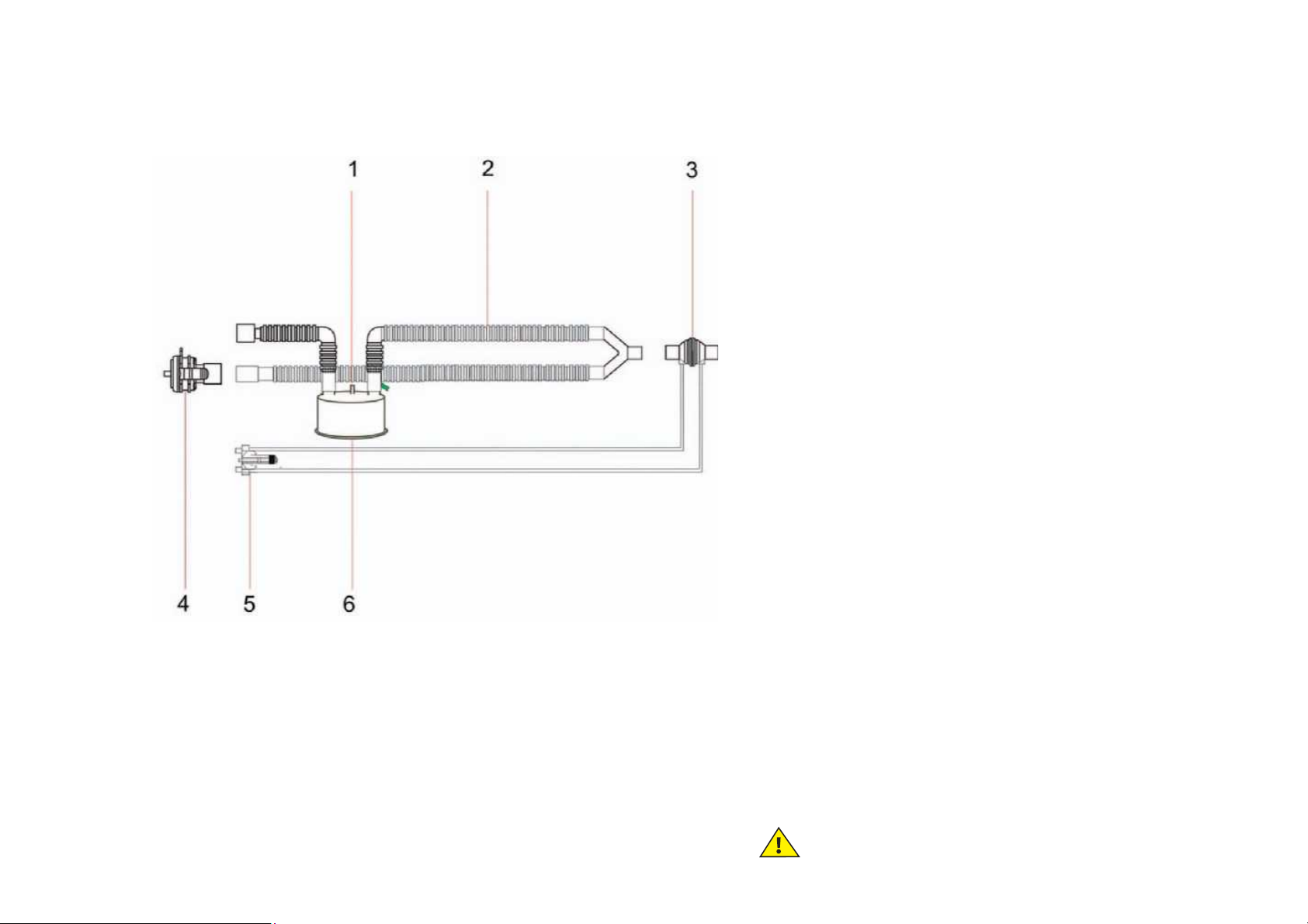
Connecting the patient tube system
Disposable tube system with humidifier
chamber
1 Humidifier chamber filling connection
2 Tube system
3 Flow sensor
4 Distal expiration valve
5 Flow sensor adapter
6 Humidifier chamber
Note safety instructions
Page 14
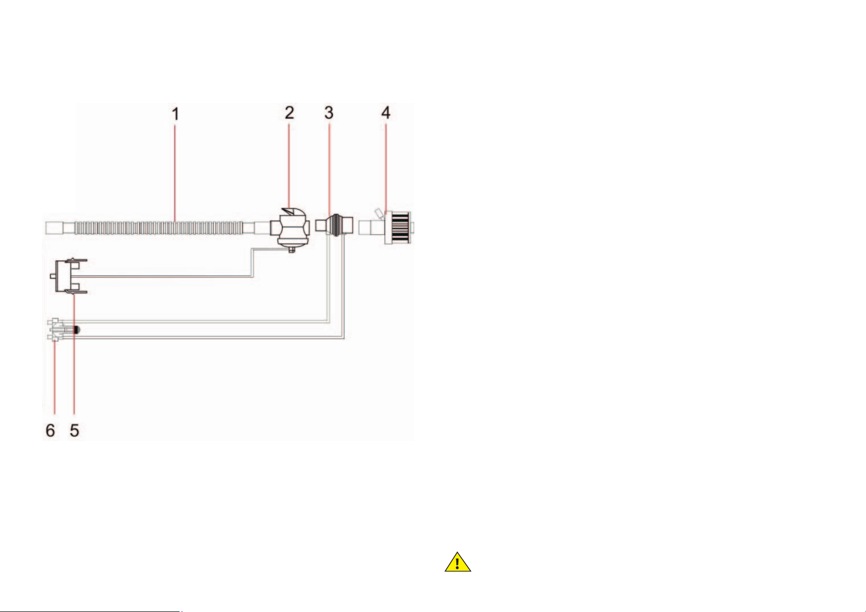
Connecting the patient tube system
Disposable tube system adults emergency
1 Tube system
2 Proximal expiration valve
3 Flow sensor for adults
4 Patient filter (optional)
5 Expiration valve adapter
6 Flow sensor
Note safety instructions
Page 15
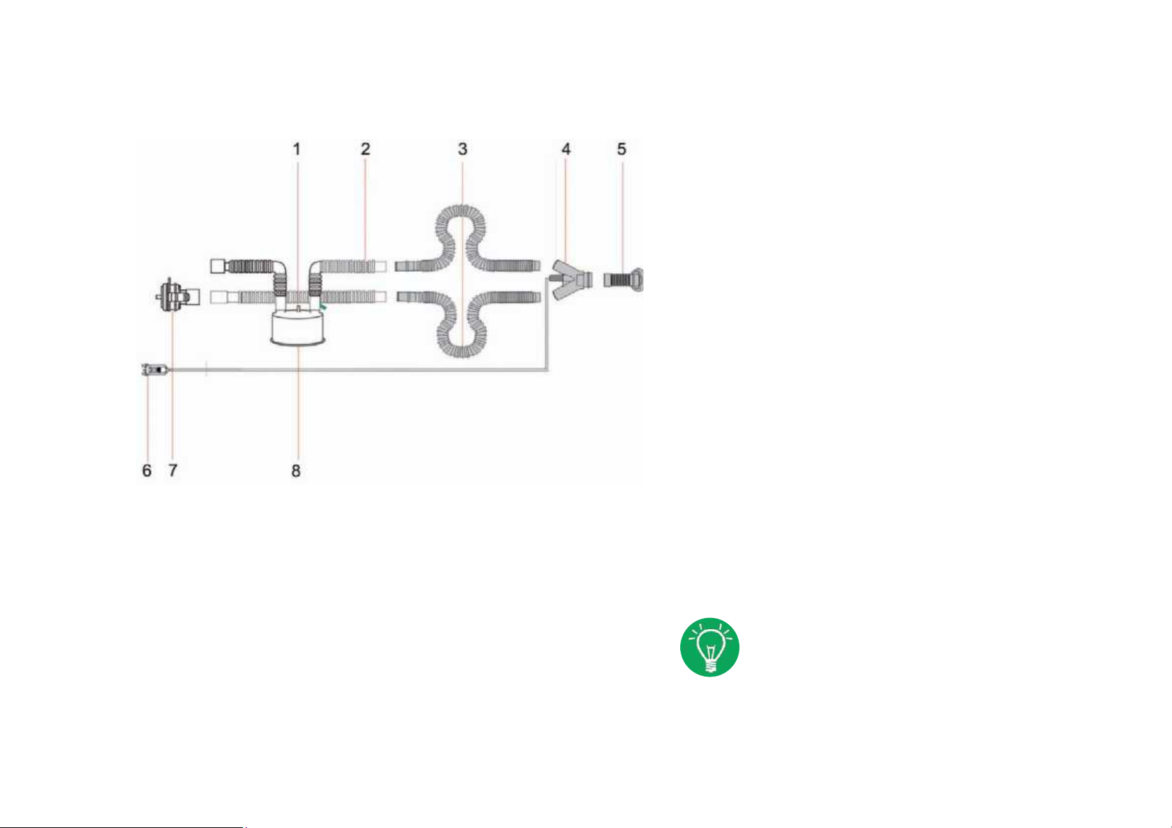
Connecting the patient tube system
EasyFlow nCPAP-System
1 Humidifier chamber filling connection
2 Tube system
3 Decoupling tube
4 Applicator
5 Prong/mask
6 Flow sensor adapter
7 Distal expiration valve
8 Humidifier chamber
The pressure measuring adapter
is not needed if an expiration
valve with pressure measurement
nozzle is used.
Page 16
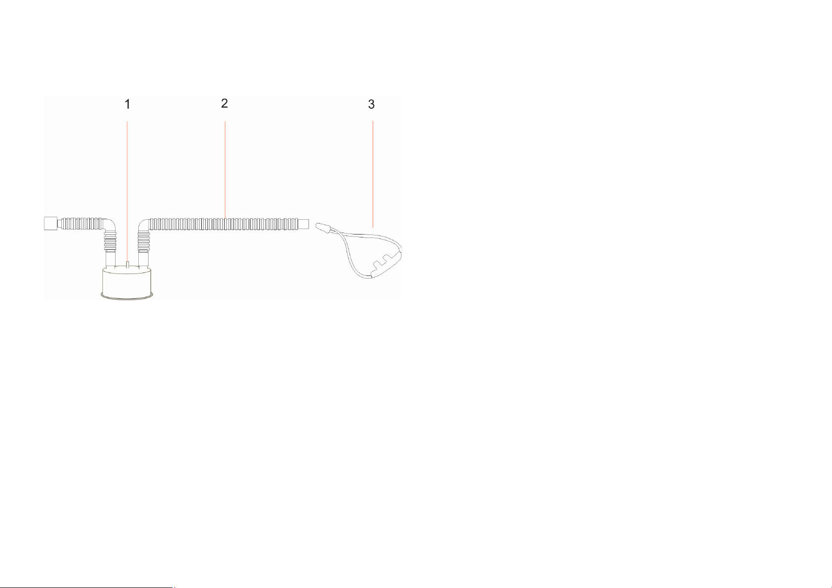
Connecting the patient tube system
HighFlow-System
1 Humidifier chamber filling connection
2 Tube system
3 HighFlow system
Page 17
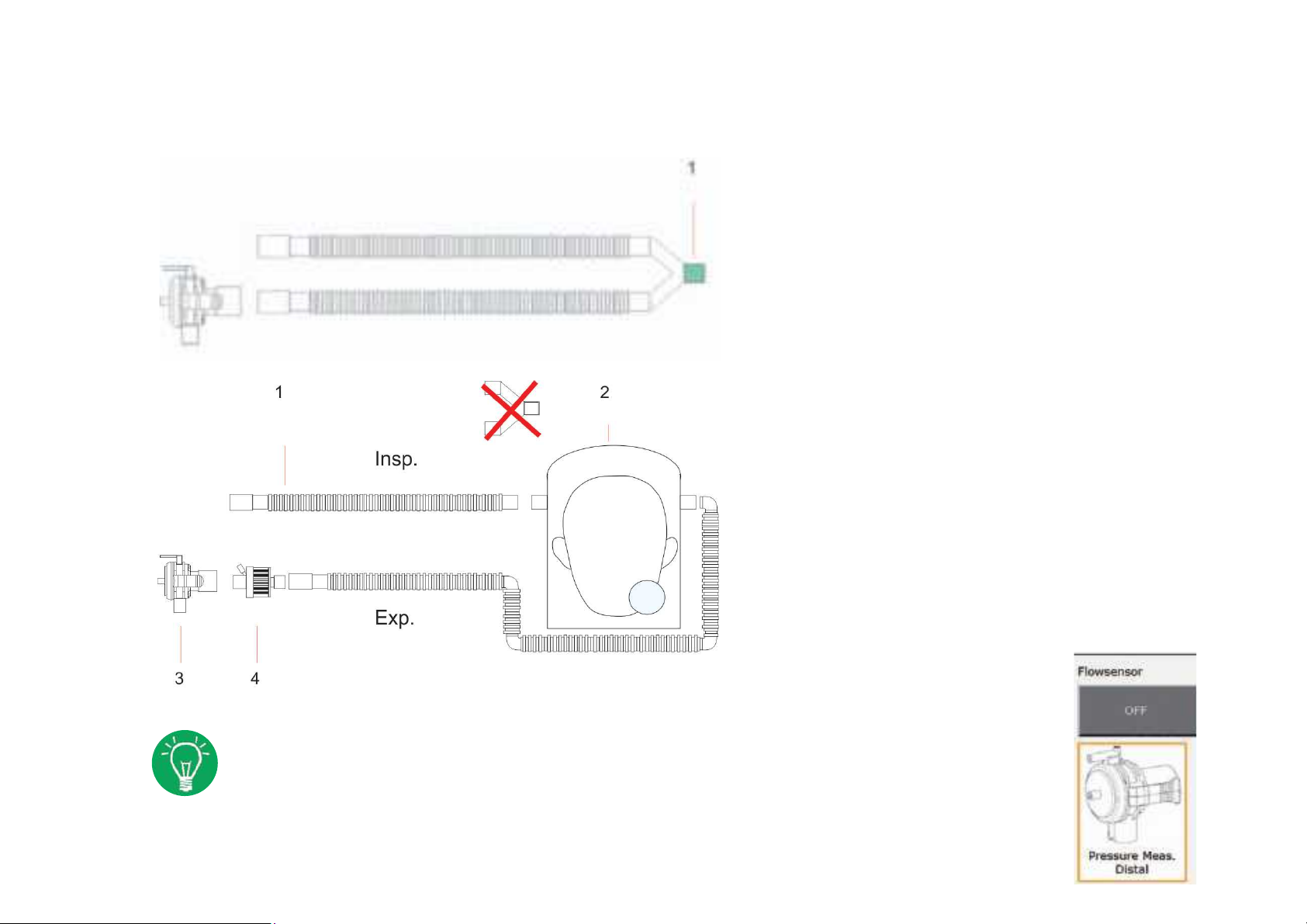
Connecting with ventilation helmet
1 Start/Test EVE with double limb tube
system (Art.-No. 107061203) and Y-piece
1 Double limb tube system
2 Ventilation helmet
3 Expiration valve with pressure
measurement (Art.-No. 107061081)
4 Bacteriafilter
Connect patient and start ventilation
Settings:
Noninvasive ventilation (PC-CMV, PC-CPAP, PC-CPAP+ PSV)
Flow sensor off • Select Expiration valve with pressure measurement port
Page 18

Installing the expiration valve
The EVE lets you use both distal (away from the
patient) and proximal (close to the patient)
expiration valves.
A proximal expiration valve is used only with the
emergency hose system for adults.
The distal expiration valve is used for all other
hose systems.
The distal expiration valve is connected directly
to the expiration port and linked to the tube
Carefully insert the expiration valve in
the corresponding connection on the right
side panel and allow to engage.
Do not tilt the expiration valve or press it in
with force. Danger of breakage!
system.
Page 19
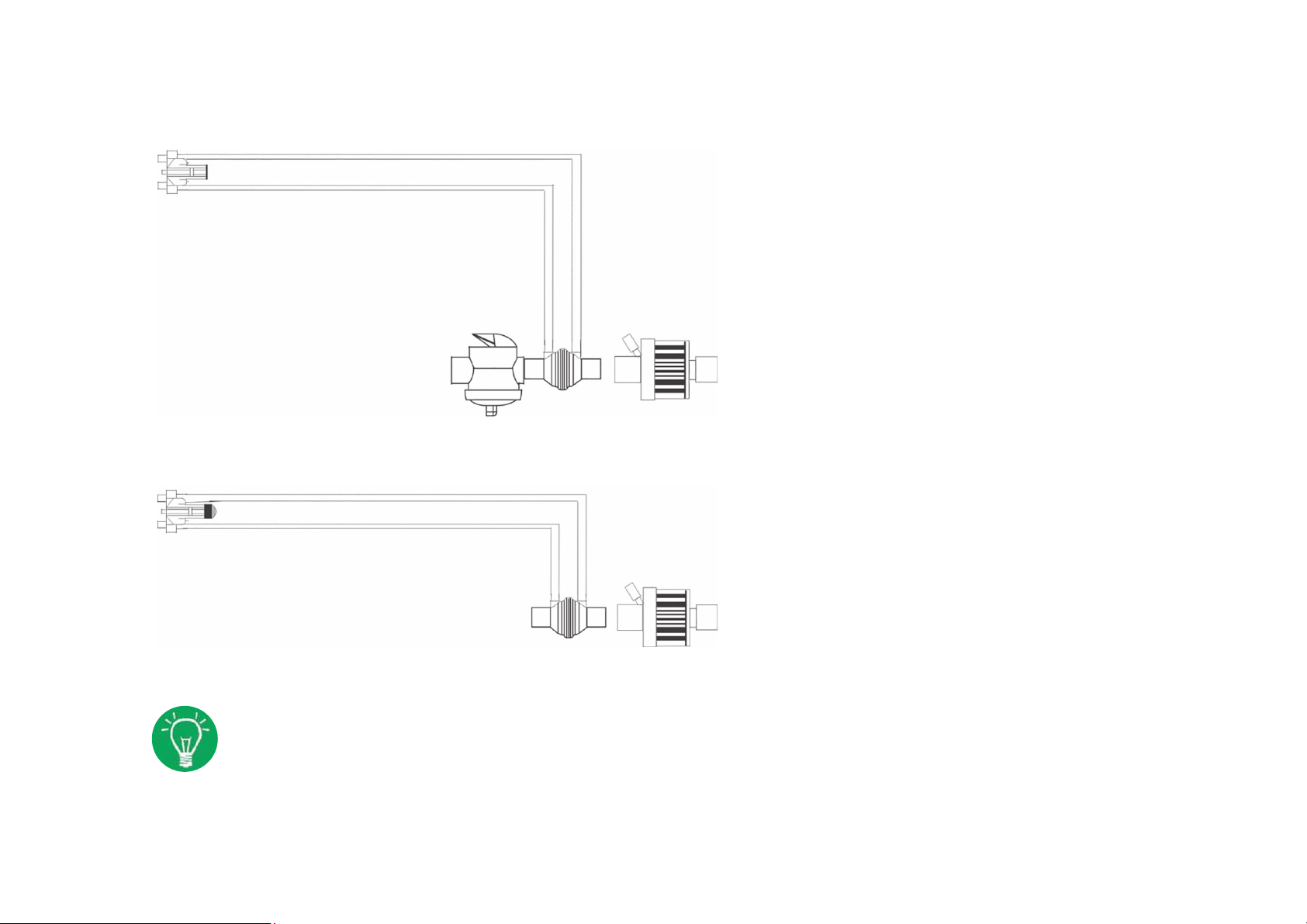
Installing the flow sensor
Flow sensor connection with proximal expiration valve
EVE measures pressure and flow via the flow
sensor (PNT). The measurement is taken
proximally between the Y-piece and the tube
connector. For this purpose, a flow sensor
head is fitted between the two parts.
The di erential pressure resulting from the
flow sensor head‘s resistor is a measure of
the volume flow. Separate flow sensors are
available for adults and children.
Flow sensor connection with distal expiration valve
Turn the flow sensor measurement line
connectors upward to prevent conden-
sate from entering the
measurement lines.
The flow sensor is connected between the
expiration valve and the endotracheal tube
(ETT). The images show the additional
connection of a bacterial
filter.
Page 20
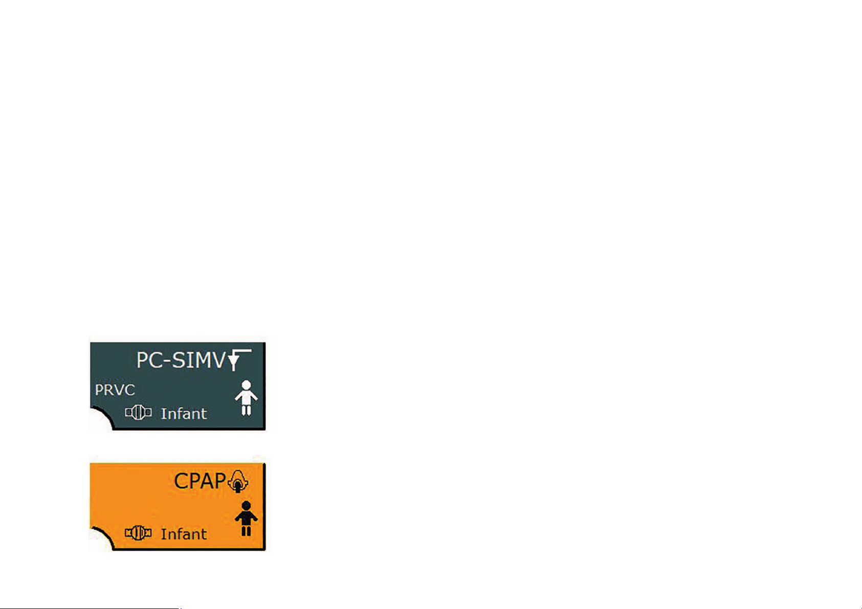
Ventilation mode display
This display indicates the current ventilation
mode, the active additional functions, the patient
type and the flow sensor type.
Selecting a non-invasive ventilation mode causes
the display to turn orange. In addition, the icon
for non-invasive ventilation appears.
1 Flow sensor type
2 Icon for invasive ventilation
3 Additional function for ventilation mode
4 Ventilation mode
5 Patient type
6 Icon for non-invasive ventilation
Selecting this field opens a ventilation
menu where you can adjust the settings
to the current ventilation scenario.
Invasive ventilation mode
Non-invasive ventilation mode
Page 21
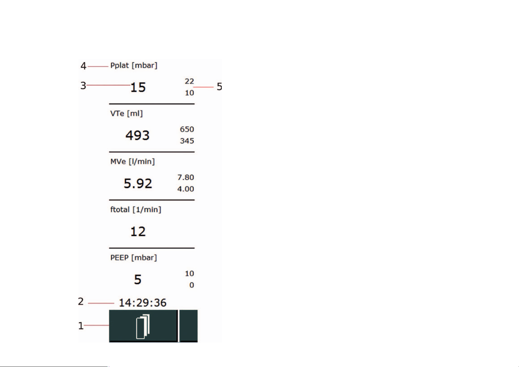
Measured value display
This display gives a quick view of the relevant
measured values together with the alarm
limits shown after the measured value.
1 Function field for toggling between the
measured value display and the display
of the active measured block
2 Time display
3 Measured value
4 Name of measured value including unit
5 Alarm limits display
Five measured values are displayed.
Three sets of 5 measured values each are
available. Only one set can be displayed
at a time. Use the function field to switch
between the sets.
Page 22
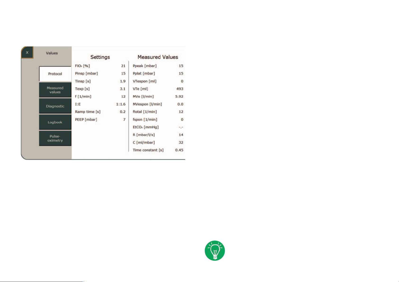
Function fields
Values
Pressing this function field opens the
„Values“ sub-menu.
This provides an overview of the
measured values currently determined
by the ventilator.
The logbook data can be saved on
the internal SD card.
Page 23

Function fields
Limits
Pressing the „Limits 1-3“ fields lets you view
all the alarm limits and adjust them to the
patient‘s needs. If limits are breached during
the current ventilation, the corresponding
parameter field turns yellow or red,
depending on the alarm priority.
1 Name and unit
Alarms
The „Alarms“ sub-menu shows the „Alarm History“
and all measured values that are monitored by
alarm limits. Pressing the „Alarm History“ field or
the alarm indicator opens a list of the seven most
recent alarms.
2 Upper limit
3 Current measured value
4 Lower limit
Page 24
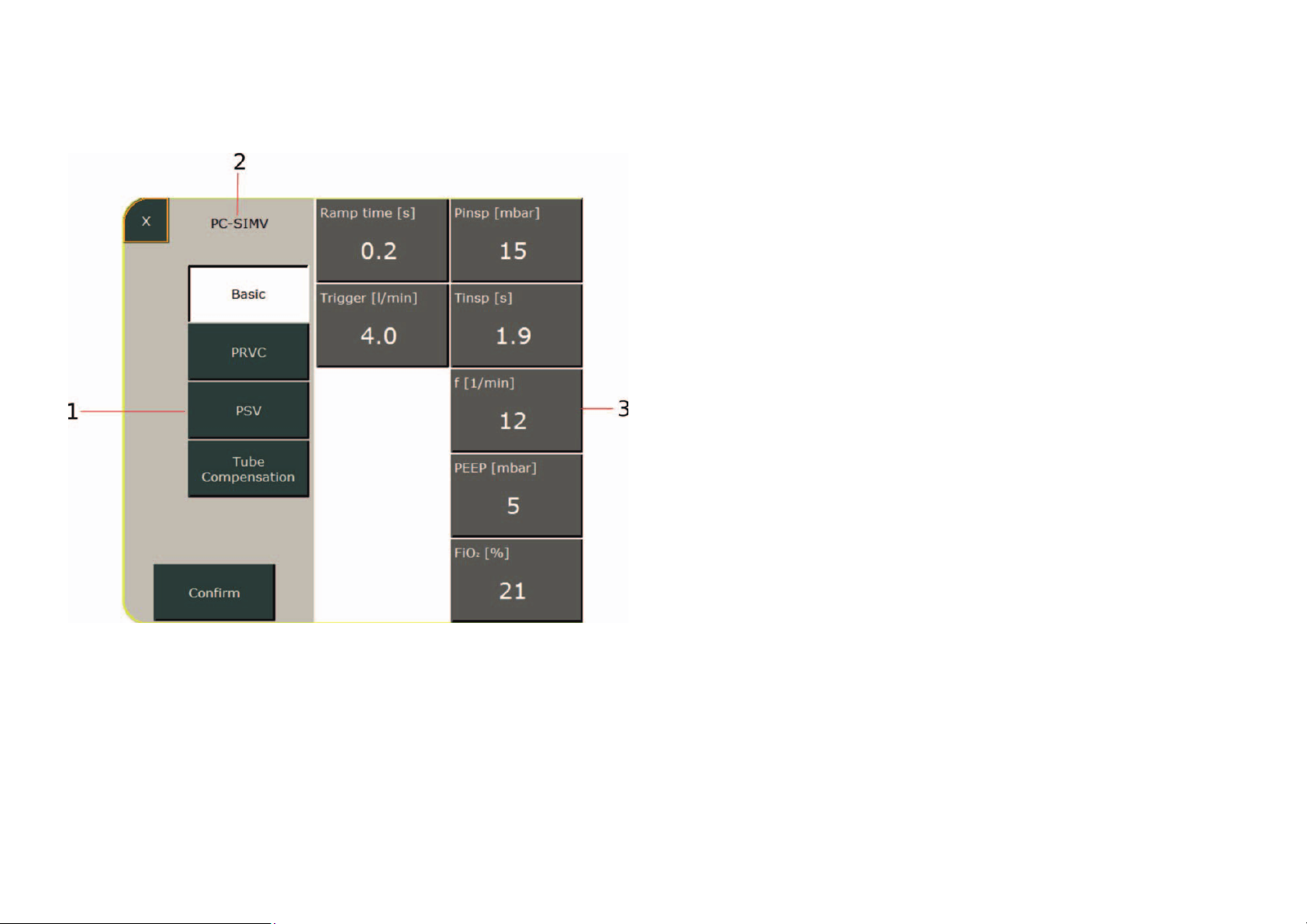
Parameters
Pressing this function field opens a sub-
menu with all configurable parameters and
additional functions for the currently active
ventilation mode.
1 Optionally selectable additional functions
2 Current ventilation mode indicator
3 Ventilation parameters
To change a parameter, select the corres-
ponding field. The field then turns orange.
You can now change the value using the
control knob. If additional functions exist for
the currently active ventilation mode, these
can also be activated from this menu. Press
the „Confirm“ field to save the new settings
and close the sub-menu.
Page 25
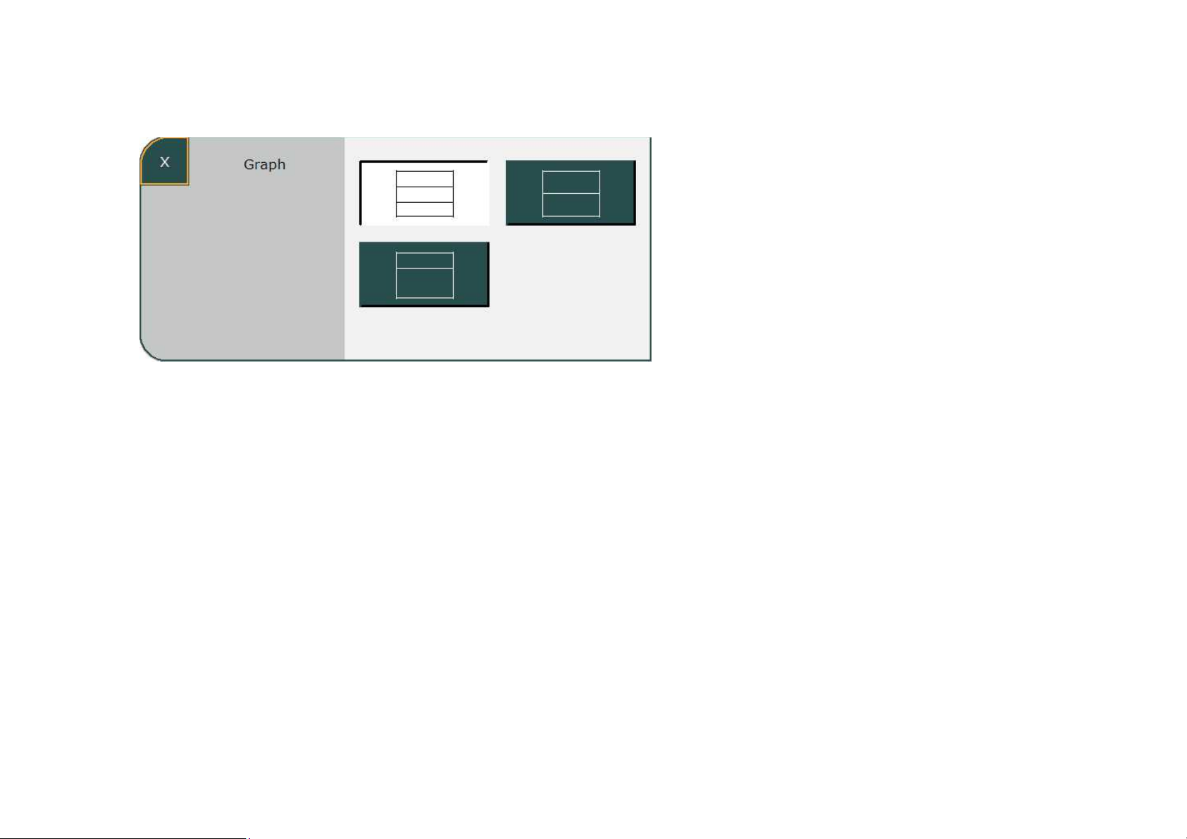
Graphic display
Pressing the „Graph“ button opens the
graphic display, which can be customized.
The initial layout can be pre-configured in
the system settings. Three different layout
versions are available.
1 Display of three curves
2 Display of two curves
3 Display of one curve, loop or trend
The top field of the graphic display always
shows the pressure curve. The remaining
fields can be freely configured by selecting
them.
Page 26
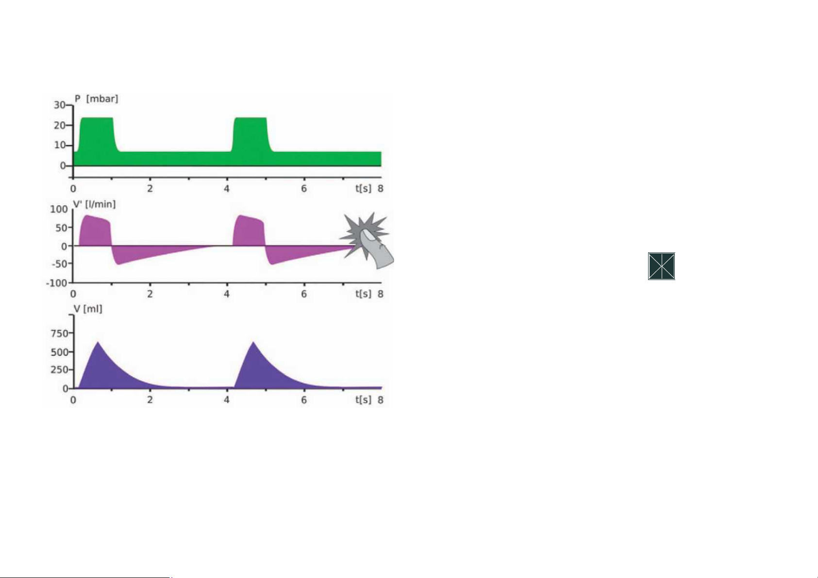
Configuring the measurement curves
Select a measurement curve on the display
to change it. A window with all available
measurement curves (volume, flow, CO
and plethysmogram) opens. You can now
select the desired option. For a better view,
the measurement curves can be frozen on
the display. To do this, press the „Stop“
field in the selection window.
A er activation, the measurement curves
run until the end of the scale and are then
frozen. This mode is ended by pressing the
„Stop“ field or automatically a er 20 s
have passed.
2
Page 27
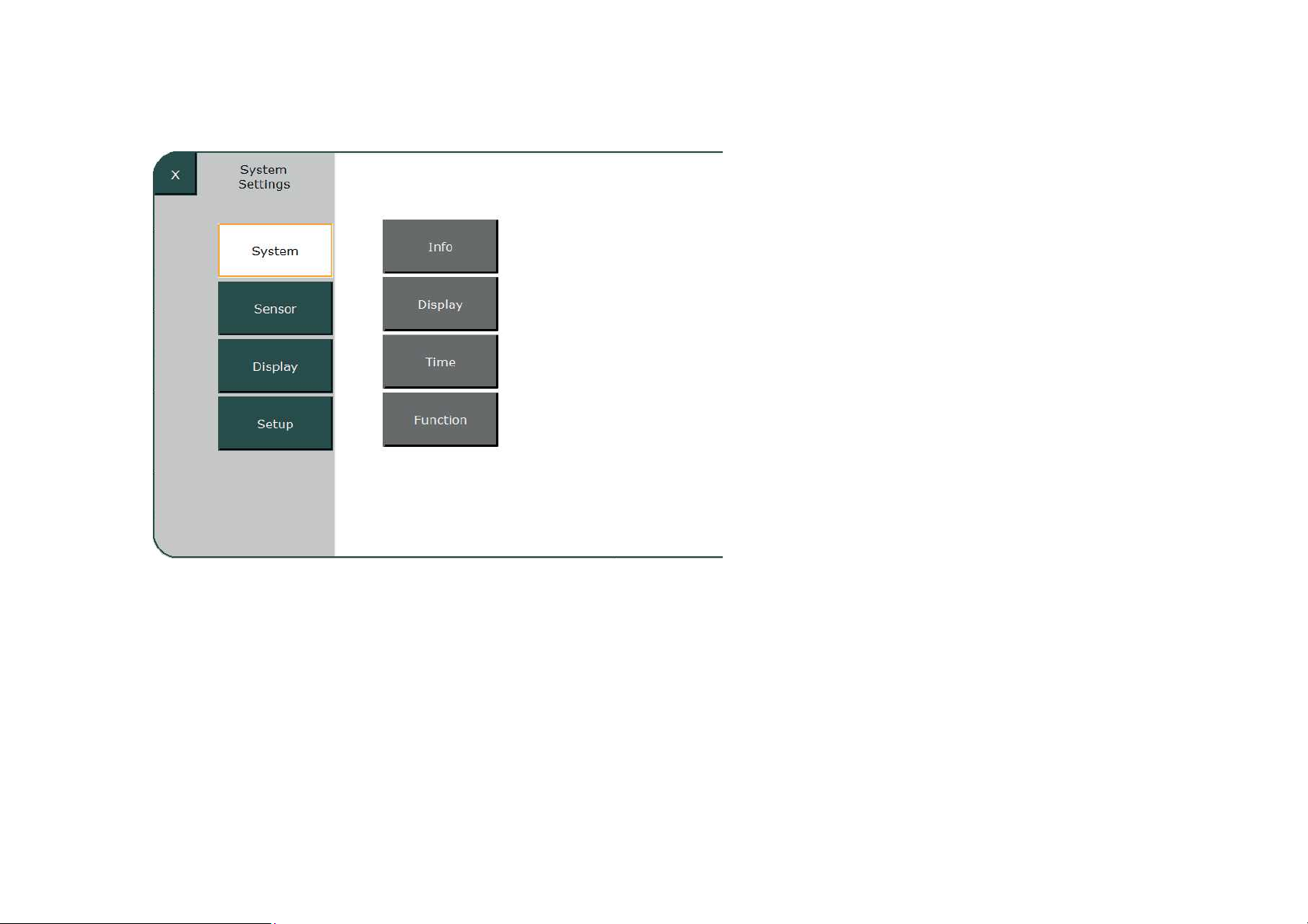
System settings
This lets you access the following sub-menus:
● Info
● Display
● Time
● Function
Page 28
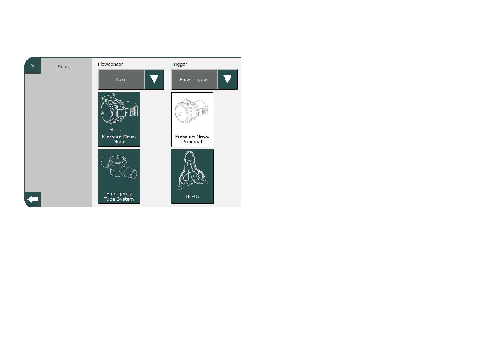
Flow
This sub-menu consists of functions to
check and configure (as needed) the
flow sensor and trigger. In addition, the
following can be selected here: use of an
expiration valve with either distal or
proximal pressure measurement and use
of either an emergency hose system or
high flow nasal cannula for ventilation.
Page 29
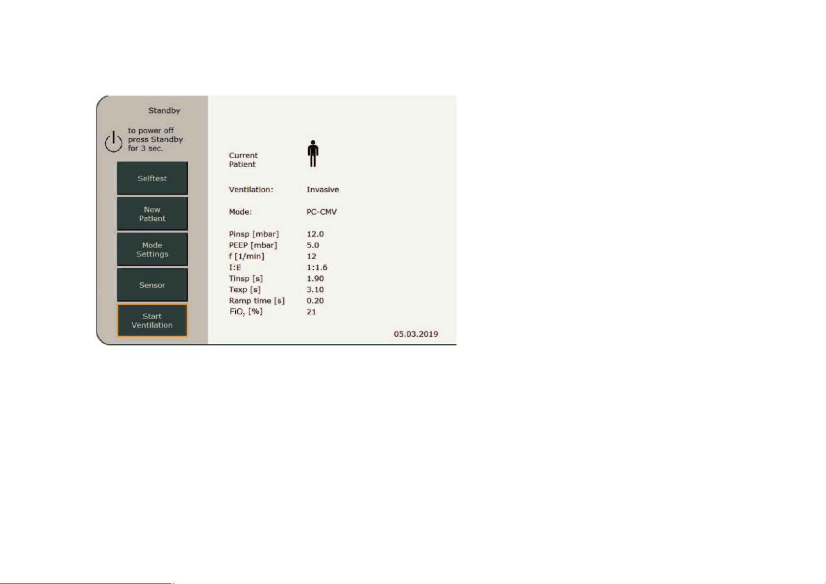
Standby mode
If the selftest is passed, the standby screen
appears. Initially, it always shows the
ventilation mode and settings for the most
recent ventilated patient. To keep these
settings, press the „Continue Ventilation“
field to activate ventilation.
Press the „New Patient“ field to create a new
patient. To switch to Standby mode from
a current ventilation process, press and hold
the „On/Off/Standby“ button for 3 s.
Page 30

Using fast tracking keys
The easiest way to start a new ventilation
process is by using the fast tracking keys on
the front panel of the ventilator.
These provide a quick and easy way to select
the default ventilation parameters for preterm
infants and newborns, children and adults.
To prevent operator errors, the desired fast
tracking key must initially be pressed for 0.5 s,
after which it starts to flash green.
Pressing the key again for 0.5 s will then start
or switch to the selected ventilation mode.
Fast tracking key assignment can be
customized in the Setup menu.
Page 31
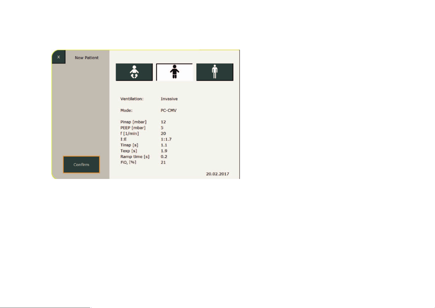
New patient
This menu lets the user switch between
settings for preterm infants and newborns,
children and adults. This selection corres-
ponds to the function of the fast tracking keys.
After selecting the patient type, the system
suggests pre-configured ventilation with
ventilation parameters adapted to the corres-
ponding patient type. Press the „Confirm“
button to save the settings and return the
ventilator to the Standby screen.
You can now select the „Start Ventilation“ field.
Press the „Mode Settings“ field to change the
ventilation mode.
Page 32
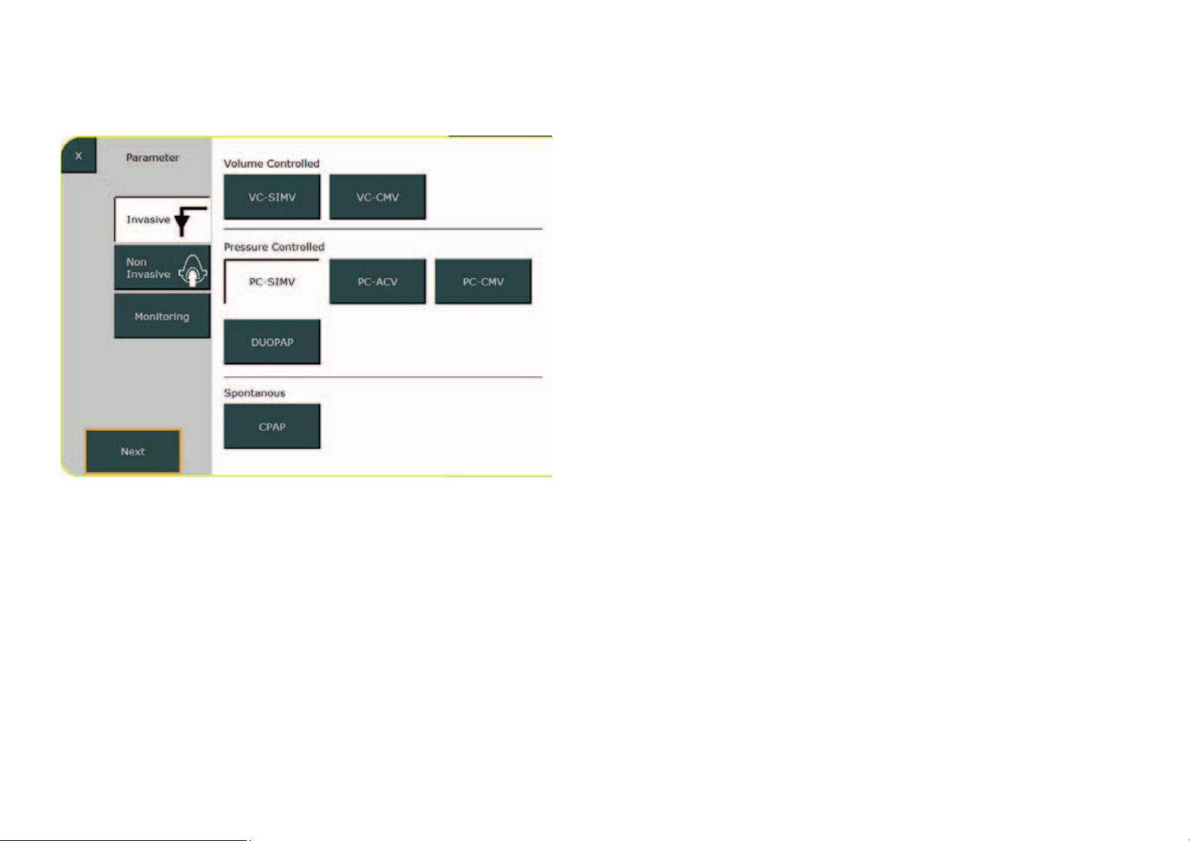
Ventilation settings
Selecting the ventilation mode
This example uses invasive PC-SIMV to
describe the selection of the ventilation
mode.
Proceed as follows: Press the „Invasive“
field in the menu. All available ventilation
modes are displayed.
Select „PC-SIMV“ and press the „Next“ field.
Page 33
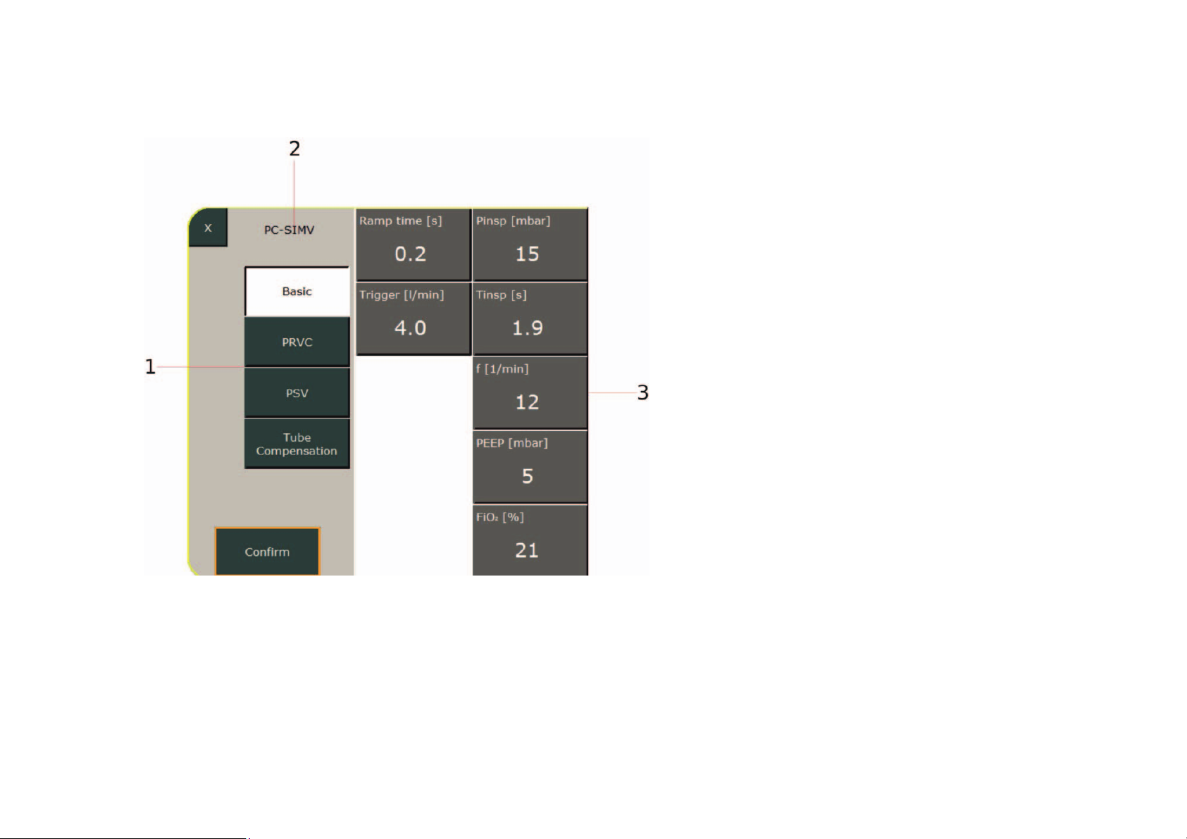
Ventilation settings
Parameters
The configuration menu for PC-SIMV opens.
1 Additional functions for the selected mode
2 Current ventilation mode
3 Configurable ventilation parameters
Possible additional options for PC-SIMV
(here PRVC and PSV) and tube compensation
are listed on the left side. The relevant confi-
gurable ventilation parameters are listed on
the right side. After the user selects the desired
PC-SIMV option, the corresponding ventilation
parameters are displayed and can be adapted
to the patient‘s needs.
Page 34
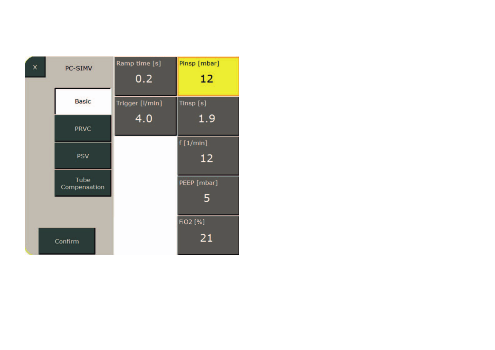
Ventilation settings
Setting parameter
The selected parameter turns yellow.
The value can now be changed using the
control knob. Press the control knob or
the „Confirm“ field to complete your entry.
Proceed analogously to configure the other
ventilation parameters.
Press the „Confirm“ button to save the
settings and return the ventilator to the
„Standby“ menu.
Select „Continue Ventilation“ to activate
the ventilation.
Page 35
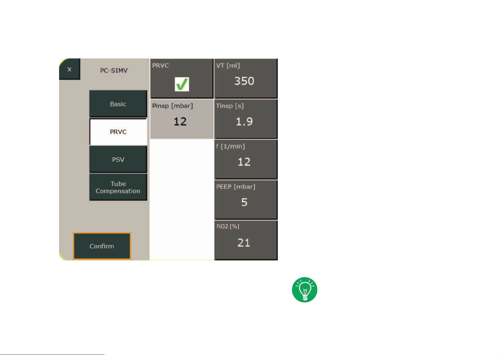
Ventilation settings
Setting parameter PRVC
This option lets the user select a target
volume that guarantees a tidal volume with
minimum required pressure during breaths.
Depending on the patient‘s spontaneous
breathing efforts and lung compliance,
the inspiration pressure varies with the
intention to apply the selected tidal volume
with the minimum required pressure.
Increase the upper pressure alarm
limit to e.g. 40 mbar to avoid pressure
limitation.
Page 36
Ventilation settings
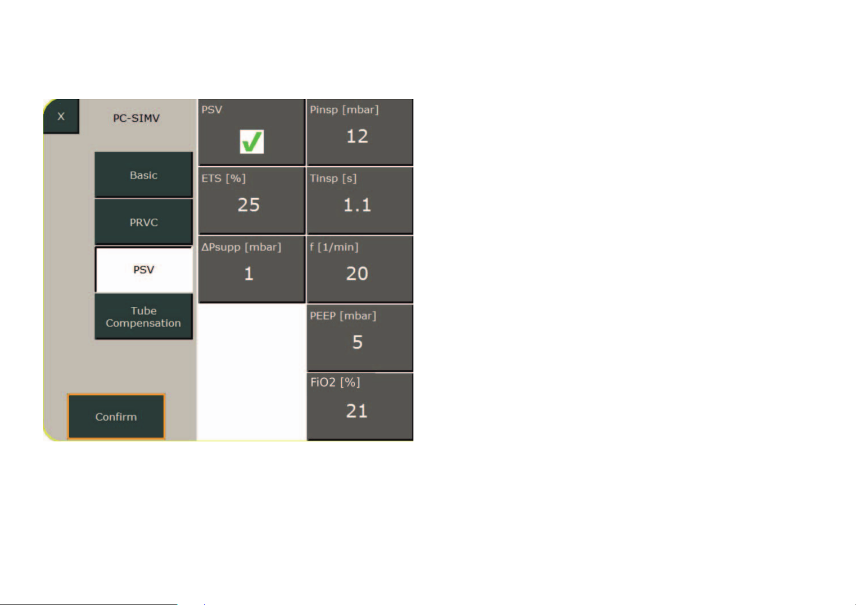
Setting parameter CPAP PSV
PSV is designed to support insufficient spon-
taneous breathing. It combines the benefits
of pressure-controlled ventilation with the
patient‘s spontaneous breathing activity.
The ventilator uses the selected trigger
threshold to detect the patient‘s inhalation
efforts and then triggers a mandatory breath
using the selected pressure support (Psupp).
With PSV enabled, the ventilator stores the
inspiratory peak flow during inhalation.
Expiration is initiated as soon as the flow has
dropped to the previously set percentage for
the inspiratory peak flow. The Expiration
Trigger Sensitivity (ETS %) is used for this
setting. In pure CPAP ventilation, the Pinsp
setting acts as an parameter for Insp.-Hold.
Page 37
Ventilation settings
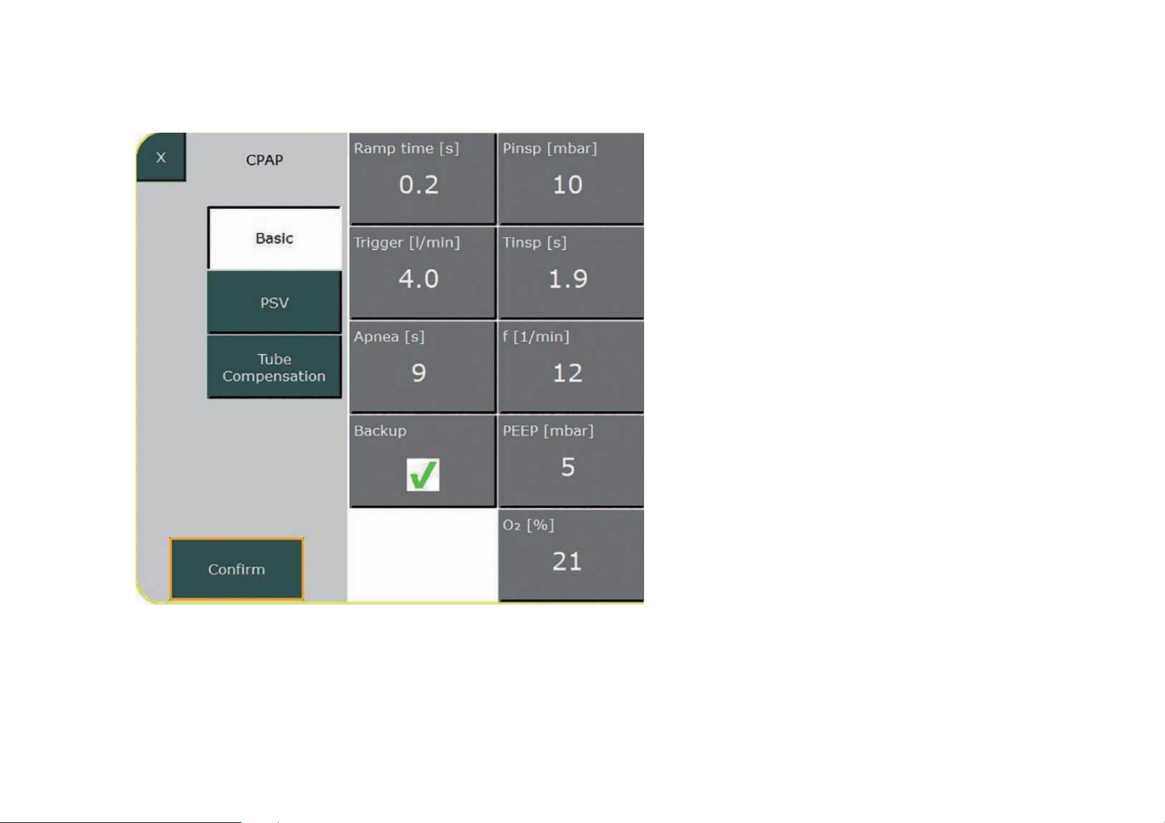
Parameter setting CPAP backup ventilation
CPAP can be combined with backup
ventilation. The user can set the maximum
desired apnea duration in the „Apnea“ field.
If there is no spontaneous breathing during
this time, the ventilator begins mandatory
ventilation using the preset parameters.
The parameter settings for backup ventilation
are comparable to PC-SIMV ventilation.
Page 38
Ventilation settings
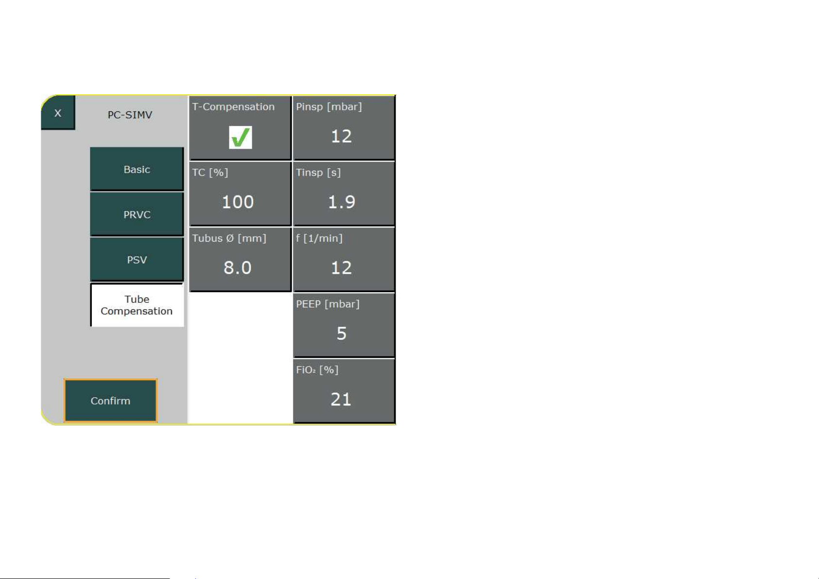
Tube compensation
All invasive ventilation modes can be
combined with tube compensation.
This function lets you adjust the ventilation
pressure to the resistance of the tracheal
or endotracheal tube.
Adjustable parameters:
• Compensation (%)
• Tube diameter (mm)
Page 39

Stop ventilation
To end the ongoing ventilation and
switch to Standby mode, press and
hold the „On/Off/Standby“ button
for 3 s.
Pressing the button for another 3 s
turns the ventilator off.
Page 40
Fritz Stephan GmbH Medizintechnik · Kirchstraße 19 · 56412 Gackenbach · Germany
Tel. +49 6439-91 25-0 · Fax +49 6439-91 25-111 · [email protected] · www.stephan-gmbh.com
 Loading...