

Page 1
Operation Manual
Page 2

Operation Manual by Ludvig Carlson, Anders Nordmark, Roger Wiklander
The information in this document is subject to change without notice and does not represent a commitment on the part of Steinberg Media Technologies GmbH. The software described by this document is subject to a License Agreement and may not be
copied to other media except as specifically allowed in the License Agreement. No part
of this publication may be copied, reproduced or otherwise transmitted or recorded,
for any purpose, without prior written permission by Steinberg Media Technologies
GmbH.
All product and company names are ™ or ® trademarks of their respective owners.
Windows 2000 and Windows XP are trademarks of Microsoft Corporation.
© Steinberg Media Technologies GmbH, 2004.
All rights reserved
.
Page 3

Table of contents
Page 4

Introduction
7
Guided tour
49
8 Welcome!
9 About the program and the
manual
Installation and
11
requirements for
Windows
12 About this chapter
12 Requirements
16 Hardware installation
18 Installing V-ST
21
Installation and
ACK
requirements for
Mac OS X
22 About this chapter
22 Requirements
25 Hardware installation
26 Installing V-ST
27
Setting up your
ACK
system
28 About this chapter
29 Setting up audio
(stand-alone)
33 Setting up MIDI
(stand-alone)
35 Setting up VST System Link
41 Activating VST System Link
43 Setting up MIDI for
VST System Link
45 Optimizing audio
performance
50 The main windows in
V-ST
ACK
VST Instruments
57
58 Introduction
58 Installing VST Instruments
60 Activating and using
VST Instruments
The Mixer
67
68 About this chapter
68 About the signal flow
69 A word about window
handling
70 Mixer overview
76 Mixer View options
82 Basic mixing procedures
85 Making EQ settings
89 Routing
93 Utility functions
Audio effects
101
102 Background
103 Installing effect plug-ins
105 Using effects
118 The Plug-in Information
window
Remote controlling
123
the Mixer
124 Background
124 Operations
127 Remote control device
specifics
V-ST
ACK
4 Table of Contents
Page 5

File handling
141
142 File Operations
Menu reference
145
146 About this chapter
146 V-ST
146 File menu
147 Edit menu
148 Devices menu
149 Help menu
151
ACK
menu
(Mac OS X only)
Index
Table of Contents 5
V-ST
ACK
Page 6

V-ST
ACK
6 Table of Contents
Page 7

1
Introduction
Page 8

Welcome!
Thank you for purchasing V-ST
Since Steinberg introduced the VST 2.0 plug-in format a few years back,
there’s been a rapid development of VST Instruments – software synthesizers and other sound sources played and controlled from within a host
application. There is now a huge number of VST Instruments available,
ranging from simple synthesizers and drum machines to exact software
replicas of vintage synths and extremely advanced sound modules with
no equivalent in hardware.
VST Instruments can often be more flexible than hardware synthesizers, allowing for total recall and full automation of all parameters, patching and mixing in the digital domain, graphic interfaces and solutions
that wouldn’t be possible in hardware, etc. However, any computer can
only play so many VST Instruments at a time – and typically, the more
advanced a VST Instrument is, the more processing power it requires.
Enter Steinberg’s VST System Link! This revolutionary system makes
it possible to have several computers working together as one large
system, with no other requirements than ASIO compatible audio interfaces with digital audio connections. Computers connected via VST
System Link will freely exchange audio and MIDI data, all in perfect
sync, creating a digital audio network system.
This provides an excellent solution to the problem of CPU-hungry VST
Instruments: let one computer play audio and MIDI tracks and dedicate another computer to running VST Instruments only, taking full advantage of all available processor power!
ACK
!
V-ST
ACK
is the perfect application for this: a stand-alone VST Instrument host, supporting up to 16 VST Instruments with full mixing capabilities and VST effect support. The VST Instruments are controlled via
MIDI over VST System Link or from a regular MIDI interface (e.g. for
live use) and the audio can be freely routed to any outputs on your audio interface. Since there is no editing, event handling, etc. all processing power can be focused on VST Instruments and effects!
We hope you will enjoy working with V-ST
Your Steinberg team.
V-ST
ACK
1 – 8 Introduction
ACK
!
Page 9

About the program and the manual
V-ST
ACK
comes for two different operating systems or “platforms”;
Windows and Mac OS X. This manual describes all features in the
program, for both platforms. While all features are available for both
platforms, items and naming may differ slightly – whenever this is the
case it is clearly mentioned in the manual text. In other words:
• If nothing else is said, all descriptions and procedures in the documentation are valid both under Windows and Mac OS X.
The screenshots are taken from the Windows version.
Key command conventions
Some key commands in V-ST
ACK
use modifier keys, some of which
are different depending on the operating system. For example, the default key command for Copy is [Ctrl]-[C] under Windows and [Command]-[C] under Mac OS X.
When key commands with modifier keys are described in this manual,
they are shown with the Windows modifier key first, in the following
form:
[Win modifier key]/[Mac modifier key]-[key]
For example,
[Ctrl]/[Command]-[C]
means “press [Ctrl] under Win-
dows or [Command] under Mac OS X, then press [C]”.
V-ST
Introduction 1 – 9
ACK
Page 10

V-ST
ACK
1 – 10 Introduction
Page 11

2
Installation and requirements
for Windows
Page 12

About this chapter
This chapter describes the system requirements and installation procedures for V-ST
ACK
for Windows. Installing V-ST
ACK
is described on page 21.
Requirements
for Mac OS X
To use V-ST
•
A PC with either Windows XP or Windows 2000 installed.
A USB Port is also required.
ACK
, you need the following:
For more details about the computer requirements, see below.
•
A compatible audio hardware.
By audio hardware we mean an audio interface capable of recording and playing back
digital audio using your hard disk as a storage medium. For use with VST System Link,
the audio interface must have an appropriate ASIO driver (see page 14) and digital inputs and outputs. For using V-ST
Windows Multimedia or DirectX drivers can be used, although we strongly recommend
ASIO drivers for best performance.
•
To be able to play VST Instruments in V-ST
ACK
without VST System Link, audio interfaces with
ACK
without using VST
System Link, you will also need at least one MIDI interface.
V-ST
ACK
2 – 12 Installation and requirements for Windows
Page 13

Computer requirements
Hardware
The absolute minimum requirements for running V-ST
ACK
on a PC
are as follows:
•
A 233 MHz Pentium computer with 128 MB of free RAM or an equivalent AMD processor.
Recommended configuration for optimum performance: Dual PIII or Athlon procesor,
1 GHz or faster with 512 MB RAM.
RAM
VST Instruments don’t necessarily require a lot of RAM. However, if
you are using a software sampler or drum machine, these typically play
the samples from RAM memory. This means the amount of RAM in the
computer limits the number (and size) of samples you can play. So, as
a general rule, “the more RAM the better” applies.
Wheel mouse
Although a regular mouse will work perfectly fine with V-ST
ACK
, we
recommend that you use a wheel mouse, as this will speed up parameter editing considerably (allowing you to change parameter values
by scrolling).
V-ST
ACK
Installation and requirements for Windows 2 – 13
Page 14
Audio hardware
V-ST
ACK
will run with audio hardware that meets the following basic
specifications:
• Stereo.
• 16 bit.
• Support of at least the 44.1kHz sampling rate.
• Is supplied with a special ASIO driver, or a DirectX or Windows Multimedia
compatible driver as described below.
❐
To be able to use V-ST
dio interface with ASIO drivers and digital inputs and outputs!
About drivers
A driver is a piece of software that allows a program to communicate
with a certain piece of hardware. In this case, the driver allows
V-ST
ACK
to use the audio hardware. For audio hardware, there are
three different cases, each requiring different driver configurations:
If the audio hardware has a specific ASIO driver
Professional audio cards often come with an ASIO driver written especially for the card. This allows for communication directly between
V-ST
ACK
and the audio card. As a result, audio cards with specific
ASIO drivers can provide lower latency (input-output delay), which is
crucial when using VST Instruments. Furthermore, the ASIO driver
provides the means to communicate with another computer via VST
System Link.
ACK
with VST System Link you must have an au-
Audio card-specific ASIO drivers are provided by the card manufacturers. Make sure to check the manufacturer’s web site for the latest
driver versions.
❐
We strongly recommend that you use ASIO compatible audio hardware
(even if you don’t plan to use VST System Link).
V-ST
ACK
2 – 14 Installation and requirements for Windows
Page 15

If the audio card communicates via DirectX
DirectX is a Microsoft “package” for handling various types of Multimedia under Windows. V-ST
ACK
supports DirectX, or to be more
precise, DirectSound, which is a part of DirectX used for audio input
and output. This requires two types of drivers:
• A DirectX driver for the audio card, allowing it to communicate with DirectX. If
the audio card supports DirectX, this driver should be supplied by the audio
card manufacturer. If it isn’t installed with the audio card, please check the
manufacturer’s web site for more information.
• The ASIO DirectX Full Duplex driver, allowing V-ST
DirectX. This driver is included with V-ST
ACK
ACK
to communicate with
, and does not require any spe-
cial installation.
• DirectX drivers allow you to use V-ST
ACK
as a stand-alone VST Instrument host, played via a regular MIDI interface. VST System Link functionality is not supported.
If the audio card communicates via Windows Multimedia system
If the card is Windows compatible, it can be used in V-ST
ACK
. The
card then communicates with Windows Multimedia system, which in
turn communicates with V-ST
ACK
. This requires two types of drivers:
• A Windows Multimedia driver for the audio card, allowing it to communicate
with the Windows Multimedia system. This driver should be supplied by the
audio card manufacturer, and is normally installed when you install the audio
card.
• The ASIO Multimedia driver, allowing V-ST
dows Multimedia system. This driver is included with V-ST
ACK
to communicate with the Win-
ACK
, and does not
require any special installation.
• Windows Multimedia drivers allow you to use V-ST
ACK
as a stand-alone
VST Instrument host, played via a regular MIDI interface. VST System
Link functionality is not supported.
Note also that with Windows Multimedia drivers, the latency is often too high to allow
comfortable real-time VST Instrument playing.
V-ST
ACK
Installation and requirements for Windows 2 – 15
Page 16

Hardware installation
Installing the audio hardware and its driver
1.
Install the audio card and related equipment in the computer, as described in the card’s documentation.
2.
Install the driver for the card.
There are three types of drivers that could apply: card-specific ASIO drivers, DirectX
drivers and Windows Multimedia drivers:
Specific ASIO driver
If your audio card has a specific ASIO driver it may be included with
the audio card, but you should always make sure to check the audio
card manufacturer’s web site for the most recent drivers. For details
on how to install the driver, refer to the manufacturers instructions.
DirectX driver
If your audio card is DirectX compatible, its DirectX drivers will most
likely be installed when you install the card (as with the Windows Multimedia driver). If you have downloaded special DirectX drivers for the audio card, you should follow the manufacturer’s installation instructions.
Windows Multimedia driver
These drivers are normally included with all types of regular PC audio
cards. Some are even included with Windows itself. Depending on
whether the audio card is “Plug’n’Play compatible” or not, the installation of the card is done differently:
• If the card is “Plug’n’Play compatible”, Windows will detect the
card once it is plugged in, and ask for the necessary driver disks.
• If not, you need to use the “Add New Hardware” feature in the Control
Panel to install the card and its drivers.
Refer to the documentation that comes with the card.
❐
Should you have an audio card but no driver, please check the manufacturers web site, or ask your music or computer dealer for help.
V-ST
ACK
2 – 16 Installation and requirements for Windows
Page 17

Testing the Card
To make sure the audio card will work as expected, perform the following two tests:
• Use any software included with the audio card to make sure you can
play back audio without problems.
• If the card is accessed via a standard Windows driver, use the Media
Player application (included with Windows) to play back audio.
Installing a MIDI interface
Installation instructions for a MIDI interface should be included with
the product. However, here’s an outline of the necessary steps:
1. Install the interface inside your computer or connect it to a “port” (con-
nector) on the computer.
Which is right for you depends on which type of interface you have.
2. If the interface has a power supply and/or a power switch, turn it on.
3. Install the driver for the interface, as described in the documentation
that comes with the interface.
It is likely that you will need a CD ROM or floppy disk supplied by the manufacturer of
the MIDI interface. Also please make sure to check the manufacturer’s web site for updated drivers.
V-STACK
Installation and requirements for Windows 2 – 17
Page 18

Installing V-STACK
Defragment the hard disk
If you plan to record audio on a hard disk where you have already
stored other files, now is the time to defragment it. Defragmentation
reorganizes the physical allocation of space on the hard disk in order
to optimize its performance using a special defragmentation program.
❐
It is crucial to the audio recording performance that your hard disk is optimized (defragmented). You should make sure to defragment regularly.
Installation
To install V-STACK, simpy run the V-STACK installer application and
follow the directions in the dialogs that appear.
• At one point during the installation, you will be asked to fill in your
serial number.
You should have received this serial number when purchasing and downloading the
program over the internet. If you purchased the CD version of the program, you will find
the serial number on the registration card in your package.
This completes the installation of your V-STACK program!
Register your software!
Registering your software will make sure you are entitled to technical
support and kept aware of updates and news regarding V-STACK.
If your computer has a working Internet connection, you can register online. From the Steinberg V-STACK program group on the Windows
Start menu, select the Registration item and follow the instructions. You
can also select this option from the Help menu of the program.
If your computer does not have a working Internet connection, you can
also register from another computer.
The items on the start menu
If you open the Windows Start menu, you will find a V-STACK group
on the “Programs” submenu. This contains the following items:
V-STACK
2 – 18 Installation and requirements for Windows
Page 19

• V-STACK Operation Manual.
Opens the manual you are reading right now.
• ASIO DirectX Full Duplex Setup.
This is where you make settings if your audio hardware uses DirectX for audio playback and recording.
• ASIO Multimedia Setup.
This opens a dialog with settings for the ASIO (Audio Stream Input Output) system,
which handles audio playback in V-STACK if you are using the ASIO MME driver. This
dialog can also be opened from within V-STACK. See the chapter “Setting up your
system” in this manual.
• V-STACK.
This launches the actual program.
There may also be additional items (such as Readme files) available on
the Start menu. Please read all such files before launching V-STACK,
since they may contain late information not included in the manual.
V-STACK
Installation and requirements for Windows 2 – 19
Page 20

V-STACK
2 – 20 Installation and requirements for Windows
Page 21

3
Installation and requirements
for Mac OS X
Page 22

About this chapter
This chapter describes the system requirements and installation procedures for V-STACK for Mac OS X. Installing V-STACK for Windows
is described on page 11.
Requirements
To use V-STACK, you need the following:
• A Macintosh computer running Mac OS X (version 10.2 or later).
For more details about the computer requirements, see below.
• Mac OS X compatible audio hardware.
While the built-in audio hardware of the Macintosh may be adequate for basic audio
playback, we strongly recommend audio hardware that is specifically designed for audio recording and music applications.
For MIDI
• At least one MIDI interface.
• At least one MIDI instrument.
• Any audio equipment necessary to listen to the sound from your MIDI
devices.
V-STACK
3 – 22 Installation and requirements for Mac OS X
Page 23

Computer requirements
Hardware – Mac
The absolute minimum requirements for running V-STACK on a
Macintosh are as follows:
• Macintosh with a G4 processor, 256 MB RAM and OS X 10.2.
We recommend 512 MB RAM or more.
RAM
Audio work requires a lot of RAM! In fact, there is a direct relation between the amount of available RAM and the number of audio channels
that you can have running. As specified earlier, 256 MB is the minimum
requirement, but as a general rule “the more the better” applies.
Hard disk size
• The size of the hard disk determines how many minutes of audio you
will be able to record.
Recording one minute of stereo CD quality audio, requires 10 MB of hard disk space.
That is, eight stereo tracks in V-STACK use up at least 80 MB of disk space per recording minute.
Hard disk speed
The speed of the hard drive also determines the number of audio
tracks you can run. That is the quantity of information that the disk can
read, usually expressed as “sustained transfer rate”. Again, “the more
the better” applies.
Mouse
Although a regular mouse will work perfectly fine with V-STACK, we
recommend that you use a wheel mouse with two mouse buttons.
• Having a wheel mouse will speed up value editing and scrolling considerably.
• If your mouse has two mouse buttons you should program the right mouse
button to generate a [Ctrl]-click (this is typically the default behaviour of the
right mouse button).
This will allow you to bring up context menus by right clicking.
V-STACK
Installation and requirements for Mac OS X 3 – 23
Page 24

Audio hardware
V-STACK will run with audio hardware that meets the following basic
specifications:
• Stereo.
• 16 bit.
• Support of at least the 44.1kHz sampling rate.
• Is supplied with proper Mac OS X (Core Audio) drivers.
A basic rule of thumb is: if the hardware works under Mac OS X, you
can use it in V-STACK.
• V-STACK also supports audio hardware with Mac OS X compliant ASIO
drivers.
ASIO drivers may provide special support for routing, monitoring, synchronization, etc.
Note that the ASIO drivers must be written specifically for Mac OS X – Mac OS 9.X
ASIO drivers cannot be used.
Using the built-in audio hardware of the Macintosh
As of this writing, all current Macintosh models have built-in 16 bit stereo audio hardware. Depending on your preferences and requirements,
this may be sufficient for use with V-STACK (although we recommend
using multi-output audio hardware). The built-in audio hardware is always available for selection in V-STACK – you don’t need to install any
additional drivers.
❐
Some Macintosh models have audio outputs but no inputs. This means
that you can only play back audio – recording is not possible without additional audio hardware.
V-STACK
3 – 24 Installation and requirements for Mac OS X
Page 25

Hardware installation
Installing the audio hardware and its driver
1. Make sure you have the latest Mac OS X drivers for the audio hardware!
Please check the manufacturer’s web site for the latest versions.
2. Install the driver(s) for the audio hardware.
This is usually done by running an installer application.
3. Install or connect the audio interface, as described in the card’s
documentation.
Installing a MIDI interface
1. Make sure you have the latest Mac OS X drivers for the MIDI interface!
Please check the manufacturer’s web site for the latest versions.
2. Install the driver(s) for the interface.
This is usually done by running an installer application.
3. Connect the MIDI interface to the computer, as described in the inter-
face documentation.
V-STACK
Installation and requirements for Mac OS X 3 – 25
Page 26

Installing V-STACK
Defragment the hard disk
If you plan to record audio on a hard disk where you have already
stored other files, now is the time to defragment it. Defragmentation
reorganizes the physical allocation of space on the hard disk in order
to optimize its performance using a special defragmentation program.
❐
It is crucial to the audio recording performance that your hard disk is optimized (defragmented). You should make sure to defragment regularly.
Installing V-STACK
To install V-STACK, simpy run the V-STACK installer application and
follow the directions in the dialogs that appear.
• At one point during the installation, you will be asked to fill in your
serial number.
You should have received this serial number when purchasing and downloading the
program over the internet. If you purchased the CD version of the program, you will find
the serial number on the registration card in your package.
This completes the installation of your V-STACK program! The installation procedure puts all files in the right places, automatically.
You can now start the program from your Applications folder. When
you launch V-STACK for the first time, you will be asked whether you
want to add a V-STACK icon to the Dock.
Register your software!
Registering your software will make sure you are entitled to technical
support and kept aware of updates and news regarding V-STACK.
If your computer has a working Internet connection, you can register
online. Launch V-STACK and select “Register Online…” from the
V-STACK menu.
If your computer does not have a working Internet connection, you can
also register from another computer.
V-STACK
3 – 26 Installation and requirements for Mac OS X
Page 27

4
Setting up your system
Page 28

About this chapter
This chapter describes how to make the necessary connections and
set up audio and MIDI in V-STACK. As already mentioned, there are
two different ways to use the program:
• As a stand-alone VST Instrument host, played via MIDI from a regular MIDI
interface.
• With VST System Link, where the VST Instruments are played by MIDI signals
from another computer in the VST System Link network.
Connections and settings are different for these two methods, and
they are described separately on the following pages.
• If you just want to get started and try out V-STACK, we recommend that
you start with setting up the program for stand-alone (non-VSL) use (see
page 29) and then move on to the chapters about VST Instruments and
mixing.
After you’ve got to know the program, go back to the section about setting up VST
System Link (see page 35).
This chapter also contains a section about optimizing your performance – see page 45.
V-STACK
4 – 28 Setting up your system
Page 29

Setting up audio (stand-alone)
This section describes how to set up your system for basic VST Instrument playback – setting up VST System Link is described on page 35.
❐
Always make all connections with all equipment turned off!
Connecting audio
Making audio connections is a relatively simply matter in V-STACK:
you just need to connect the outputs on your audio interface to your
listening equipment, recording devices, etc.
• If you are using an audio interface with a single stereo output, you would typically connect the outputs to an amplifier, powered monitors, headphones, etc.
• If your audio interface has more than a single stereo output, you would typically connect the outputs to a hardware mixer.
Driver and helper application setup
The audio hardware setup application
Most audio cards come with one or more small applications that allow
you to configure the inputs of the hardware to your liking.
This includes:
• Selecting which outputs are active.
• Setting levels for the outputs, so that they match the equipment you use for
monitoring.
For more details about your audio hardware setup application please
refer to the documentation that came with the hardware.
V-STACK
Setting up your system 4 – 29
Page 30
VST Multitrack setup – Basic Settings
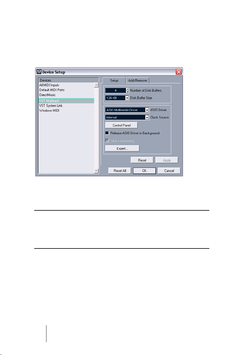
1. In V-STACK, select Device Setup from the Devices menu and click on
VST Multitrack in the list.
Make sure the “Setup” tab is selected.
The VST Multitrack panel in the Device Setup dialog.
2. Select your audio hardware from the ASIO Driver menu.
There may be several options here that all refer to the same audio hardware:
❐
We strongly recommend that you access your hardware via an ASIO
driver written specifically for the hardware, if available. If no ASIO driver is
installed we recommend that you check with your audio hardware manufacturer if they have an ASIO driver available, for example for download
via the Internet.
3. Bring up the control panel for the audio hardware and adjust the set-
tings as recommended by the audio hardware manufacturer.
V-STACK
4 – 30 Setting up your system
Page 31

• Normally, you can open the control panel by clicking the Control Panel
button in the VST Multitrack panel.
The control panel that appears when you click this button is provided by the audio
hardware manufacturer and not V-STACK (unless you use DirectX or MME, see below). Hence it will be different for each audio card brand and model. The settings may
include options for buffering, synchronization, digital input and output formats etc.
The Control panels for the ASIO Multimedia and ASIO DirectX drivers are an exception, as they are provided by Steinberg. They provide their own help information,
opened by clicking the Help button in the respective dialog. See also the notes below.
• If you are using non-ASIO audio hardware under Mac OS X, you will
find the control panel for your audio hardware in the System Preferences (“Other” section), opened from the Apple menu or from the Dock.
If you are using the built-in audio hardware of the Macintosh, you use the “Sound” control panel in the System Preferences to set levels, balance, etc.
4. If you plan to use several audio applications simultaneously, you may
want to activate the option “Release ASIO Driver in Background”.
This will allow another application to play back via your audio hardware even though V-STACK is running.
The application that is currently active (i.e. the “top window” on the desktop), will get
access to the audio hardware. Make sure that any other audio application accessing
the audio hardware is also set to release the ASIO (or Mac OS X) driver so V-STACK
can use it when becoming the active application again.
5. Click Apply and then OK to close the dialog.
V-STACK
Setting up your system 4 – 31
Page 32

If you are using audio hardware with a DirectX driver (Windows only)
If your Windows audio hardware doesn’t have a specific ASIO driver,
a DirectX driver is the next best option for stand-alone use. An ASIO
DirectX driver is available with V-STACK, “ASIO DirectX Full Duplex”.
❐
Windows 2000 users should use DirectX version 8.1.
When the ASIO DirectX Full Duplex driver is selected in the Device
Setup you can open the ASIO Control Panel and adjust the following
settings (for more details, click the Help button in the control panel):
• Direct Sound Ports
In the list to the left in the window, all available Direct Sound output ports are listed. In
many cases, there will only be one port in each list. To activate or deactivate a port in the
list, click the check box in the left column.If the check box is ticked, the port is activated.
• You can edit the Buffer Size and Offset settings in this list if necessary, by
double clicking on the value and typing in a new value.
In most cases the default settings will work fine. The audio buffer is used when audio
data is transferred between V-STACK and the audio card. Having a large buffer ensures that playback will occur without glitches. However, the time between the moment V-STACK sends out the data and when it actually reaches on the output the
"latency" will be longer.
If you are using audio hardware with a Windows Multimedia (MME)
driver (Windows only)
When you select the ASIO Multimedia Driver for the first time, the system will ask you whether you want to test the configuration. We strongly
recommend that you perform this test. If it fails, or if you for other reasons need to make adjustments to your ASIO Multimedia configuration,
click the Control Panel button to open the ASIO Multimedia Setup control panel included with V-STACK. This control panel comes with an
HTML Help describing the features and procedures.
V-STACK
4 – 32 Setting up your system
Page 33

Setting up MIDI (stand-alone)
This section describes how to connect and set up MIDI for basic VST
Instrument playback – setting up MIDI with VST System Link is described on page 43.
❐
Always make all connections with all equipment turned off!
Making connections
Since V-STACK doesn’t control external instruments and sound modules via MIDI, we don’t have to worry about any MIDI devices other
than the MIDI interface and the keyboard (or similar) you will use to
play the VST Instruments:
1. Connect a MIDI cable from the MIDI output of your MIDI keyboard to a
MIDI input on your MIDI interface.
2. If your MIDI interface has more than one input, you may want to con-
nect another keyboard or MIDI controller to that, in the same way.
For each VST Instrument in V-STACK you can specify which MIDI input should be used
– this allows you to play several different VST Instruments at the same time if you like.
• There is one case when you need to use two-way MIDI connections: if
you are using a remote control device to control the Mixer in V-STACK.
Some of these devices feature “MIDI feedback” in the form of indicators, displays or
motorized controls on the device. For these to work properly you need to connect a
MIDI cable from the MIDI Out on your MIDI interface to the MIDI In on the remote device. See page 124 for details.
V-STACK
Setting up your system 4 – 33
Page 34

Setting up MIDI ports in V-STACK
The Device Setup dialog lets you set up your MIDI system in the following ways:
• Note: After changing a setting in the Device Setup dialog, you should
click Apply and then click OK to close the dialog.
Showing or hiding MIDI Ports
Under Windows, the MIDI ports are listed in the Device Setup dialog
on the DirectMusic page and/or the Windows MIDI page (depending
on your system). By clicking in the “Show” column for a MIDI input or
output, you can specify whether or not it should be listed on the MIDI
pop-up menus in the program.
Under Mac OS X, you can hide or show MIDI ports on the MIDI System page in the Device Setup dialog.
• Hiding a MIDI port from view does not turn it off if it’s already selected as
input for a VST Instrument.
Setting up the “All MIDI Inputs” option
When you play VST Instruments in V-STACK, you can specify which
MIDI input each instrument should use. However, you can also select
the “All MIDI Inputs” option, which causes any MIDI data from any
MIDI input to be sent to the instrument.
The All MIDI Inputs page in the Device Setup dialog allows you to
specify which inputs should be included when you select All MIDI Inputs for a VST Instrument. This can be especially useful if your system
provides several instances of the same physical MIDI input – by deactivating the duplicates you make sure only the desired MIDI data is
sent to the instrument.
All done!
Now you are ready to play VST Instruments in V-STACK from your
MIDI controller keyboard. If you want to set up the program for VST
System Link, read on. If you want to get to know the program, go to
page 49.
V-STACK
4 – 34 Setting up your system
Page 35

Setting up VST System Link
Introduction
VST System Link is a network system for digital audio that allows you
to have several computers working together in one large system. Unlike conventional networks it does not require Ethernet cards, hubs, or
CAT-5 cables; instead it uses the kind of digital audio hardware and
cables you probably already possess in your studio.
VST System Link has been designed to be simple to set up and operate, yet give enormous flexibility and performance gains in use. It is capable of linking computers in a “ring” network (the System Link signal
is passed from one machine to the next, and eventually returns to the
first machine). VST System Link can send its networking signal over
any type of digital audio cable, including S/PDIF, ADAT, TDIF, or AES,
as long as each computer in the system is equipped with a suitable
ASIO compatible audio interface.
In the case of V-STACK, VST System Link allows you to use the program as a dedicated VST Instrument device, played and controlled
from another computer in the VST System Link network. You may listen to the audio signals from the VST Instruments in V-STACK directly
from the V-STACK computer, or you can route them to the application
on the other computer.
V-STACK
Setting up your system 4 – 35
Page 36

Requirements
The following equipment is required for VST System Link operation
with V-STACK:
• One computer running V-STACK.
• At least one other computer running a VST System Link compatible
application (e.g. Cubase SX, Cubase 5.2s or Nuendo 1.6 or later).
The computers can be of the same type or use different operating systems. For example, you can link an Intel-based PC to an Apple Macintosh without problems.
• Each computer must have audio hardware with specific ASIO drivers,
installed and working.
• The audio hardware must have digital inputs and outputs.
Of course, to be able to connect the computers the digital connections must be compatible (i.e. the same digital formats and connection types must be available).
• At least one digital audio cable for each computer in the network.
• To be able to hear the audio, one of the computers needs to have
more than one physical set of audio outputs.
When using V-STACK with e.g. Cubase SX, you would typically want the Cubase SX
computer to have one set of outputs (digital) connected to the V-STACK computer via
VSL and another set of outputs (analog or digital) connected to your listening equipment.
V-STACK
4 – 36 Setting up your system
Page 37

Making connections
Below, we will assume that you are connecting two computers.
Should you have more than two computers, it’s still best to start with
two and add the others one by one once the system is working – this
makes troubleshooting easier if you run into problems. For two computers, you will need two digital audio cables, one in each direction:
1. Connect a digital audio cable from the digital output of the V-STACK
computer to the digital input of the other VST System Link computer.
2. Connect the other cable from the digital output of another VST Sys-
tem Link computer to the digital input of the V-STACK computer.
• If a card has more than one set of inputs and outputs, choose which-
ever one that suits you – for simplicity usually the first set is best.
3. Connect the other VST System Link computer to your listening equip-
ment, using an additional set of outputs (analog or digital).
With this connection, signals will be sent in the following way:
Computer running
V-STACK.
This setup allows you to mix all sound sources in the other application (VST
Instruments from V-STACK and audio tracks from the other application), with
common mixer automation.
MIDI
Audio
Computer running
Cubase SX etc.
Audio
Mixer, monitors,
etc.
• If there are additional outputs available for both computers, you could
also consider connecting both computers to an external mixer.
This would give you the following signal paths:
Computer running
V-STACK.
Audio
With this setup, a mixer is required (if you want to listen to the audio from both
computers). All mixing is done separately for the two applications and you cannot
automate the mixing of the VST Instrument channels.
MIDI
Mixer
Computer running
Cubase SX etc.
Audio
Monitors, etc.
V-STACK
Setting up your system 4 – 37
Page 38

Setting up clock sync
Before you proceed you need to make sure that the clock signals on
your ASIO cards are synchronized correctly. This is essential when
cabling any kind of digital audio system, not just VST System Link.
❐
All digital audio cables by definition always carry a clock signal as well as
audio signals, so you don't need to use a special Word Clock input and
output for this (although you may find that you get a slightly more stable
audio system if you do, especially when using multiple computers).
The Clock Mode or Sync Mode is set up in the audio hardware’s
ASIO Control Panel. In V-STACK, you proceed as follows:
1. Pull down the Devices menu and open the Device Setup dialog.
2. Select the VST Multitrack device and make sure the Setup tab is se-
lected to the right.
3. Click the Control Panel button.
The ASIO Control Panel appears.
4. Open the ASIO Control Panel on the other computer as well.
Please check the documentation for the other VST System Link application for details
on how to open the ASIO Control Panel (hint: in Steinberg’s Nuendo and Cubase SX,
the procedure is the same as in V-STACK).
5. Now, you need to make sure that one audio card (and only one!) is set
to be the Clock Master, and all the other cards must be set to listen
for the clock signal coming from the Clock Master i.e. they must be
Clock Slaves.
The naming and procedure for this differs depending on the audio hardware – consult
its documentation if required.
• Typically, the ASIO Control Panel for an audio card contains some in-
dication of whether the card receives a proper sync signal or not, and
the sample rate of that signal.
This is a good indication that you have connected the cards and set up clock sync
properly. Check your audio hardware’s documentation for details.
V-STACK
4 – 38 Setting up your system
Page 39

❐
It’s very important that one and only one card is the clock master, otherwise the network cannot function correctly. Once you have set this up, all
the other cards in the network will take their clock signal from this card
automatically.
The only exception to this procedure is if you are using an external
clock – which could be from a digital mixing desk or special Word
Clock synchronizer for example. If so, you must then leave all your
ASIO cards in Clock Slave or AutoSync mode, and make sure that
each of them is listening for the signal coming from the synchronizer,
usually passed through your ADAT cables or Word Clock connectors
in a daisy chain fashion.
Minimizing the latency
The general definition of latency is the amount of time it takes any system to respond to whatever messages are sent to it. For example, if
your system’s latency is high and you play VST instruments in real
time, you will get a noticeable delay between when you press a key
and when you hear the sound of the VST instrument. Nowadays, most
ASIO-compatible audio cards are capable of operating with very low
latencies. Also, all VST applications are designed to compensate for
latency during playback, making the playback timing tight.
However, the latency time of a VST System Link network is the total
latency of all the ASIO cards in the system added together. Therefore
it’s extra important to minimize the latency times for each computer in
the network.
• The latency does not affect the synchronization – it's always perfectly in
time. But, it can affect the time it takes to send and receive MIDI and audio signals, or make the system seem sluggish.
To adjust the latency of a system, you typically adjust the size of the
buffers in the ASIO Control Panel – the lower the buffer size, the lower
the latency. Generally speaking it's best to keep to fairly low latencies
(buffer sizes) if your system can handle it – about 12 ms or less is usually a good idea.
V-STACK
Setting up your system 4 – 39
Page 40

Setting up your software
Now it’s time to set up your programs. For details on how to perform
the steps below in the other VST System Link application, see its documentation.
Setting up inputs and outputs
1. In the other VSL application, enable the desired number of outputs.
You need one output bus (digital output) for VST System Link connected to the V-STACK
computer, and one or more output buses (analog or digital outputs) connected to your listening equipment, mixer, etc.
2. Enable the desired number of audio inputs in the other application.
To make it simple you will probably want to enable all inputs available in the cable you
are using. For example, if you are using an ADAT connection this would mean activating the first four stereo input pairs. See the documentation for the program for details
on how to do this.
3. In V-STACK, open the VST Outputs window from the Devices menu.
This shows all available output buses – the number of stereo buses corresponds to the
number of outputs on your audio interface.
4. Enable the output buses you need.
Usually these should match up to the input buses you enabled in the other application.
In our ADAT example, this would mean the first four stereo outputs.
Now, the audio output of the VST Instruments in V-STACK will be sent
via the digital connection into the other computer. However, there’s
still no MIDI connection – first you have to activate VST System Link.
V-STACK
4 – 40 Setting up your system
Page 41

Activating VST System Link
After setting up the inputs and outputs, you now need to define which
input/output should carry the actual VST System Link information.
The System Link networking signal is carried on only one bit of one
channel. This means that if you have an ADAT based system which
normally carries eight channels of 24-bit audio, once you activate VST
System Link you will have seven channels of 24-bit audio and one
channel of 23-bit audio (the least significant bit of this last channel is
what we will use for networking). In practice this makes no discernible
difference to the audio quality, since you will still have around 138dB
headroom on this channel.
To set things up we need to open the VST System Link panel:
1. Open the Device Setup dialog on the Devices menu.
2. Select the VST System Link device and make sure the Setup tab is
selected to the right.
V-STACK
Setting up your system 4 – 41
Page 42

3. Use the ASIO Input and ASIO Output pop-up menus to define which
channel should be the networking channel (and thus become a 23-bit
audio channel, in our example).
Quite often you will be able to just leave these pop-ups the way they are.
4. Click the Active checkbox at the top of the panel.
5. Repeat the steps above for every computer on the network.
As the computers are made active, you should see the small T (Transmit) and R (Receive) lights flashing on each active computer, and the
name of each computer should appear in the list at the bottom of the
pane. Each computer is assigned a random number – don't worry
about this, it's just so the network knows internally which one is which.
• You can double click on the name in bold (which is the name of the
computer you’re currently working on) and set it to whatever other
name you wish.
This name will appear in the System Link window of every computer on the network.
• If you don't see the name of each computer appearing once you have
made it active, you may have to check your settings.
Go through the procedure above again and make sure that all ASIO cards are listening
to the digital clock signals correctly, and that each computer has the correct inputs
and outputs assigned to the System Link network.
V-STACK
4 – 42 Setting up your system
Page 43

Setting up MIDI for VST System Link
VST System Link supplies up to 16 MIDI ports, each with 16 channels. You set this up as follows:
1. In the VST System Link Setup tab in V-STACK, use the MIDI Ins and
Outs value boxes to specify the number of MIDI input ports you need.
For V-STACK you don’t need any MIDI output ports.
2. In the other application, specify the same number of MIDI output ports.
3. If you now check the MIDI input pop-up menu for a VST Instrument in
V-STACK, you will find the specified System Link ports added to the
list of MIDI inputs.
Similarly, MIDI tracks in the other application will have a number of System Link MIDI
output ports.
To route a MIDI track from the other application to a VST Instrument in
V-STACK, proceed as follows:
4. Select a System Link port as output for the MIDI track.
5. Select the same System Link port on the MIDI input pop-up menu for
the VST Instrument in V-STACK.
Now, any MIDI data played back on the MIDI track is routed to the
VST Instrument. To play the VST Instrument live, you would need to
activate MIDI thru/monitoring for the track or record enable it (depending on the application), so that incoming MIDI is routed to the
track’s output (i.e. to the VST Instrument in V-STACK).
V-STACK
Setting up your system 4 – 43
Page 44

The “Active ASIO Ports for Data only” setting
If you are sending huge amounts of MIDI data at once, there is a small
possibility that you might run out of bandwidth on your VST System
Link network. This will manifest itself by notes “choking” or timing becoming erratic.
If this happens, you can devote more bandwidth to MIDI by selecting
Active ASIO Ports for Data only in the VST System Link Setup panel.
When this is active, the VST System Link information will be sent on
the entire channel instead of just one bit, more than enough for all the
MIDI you could ever hope to use. The downside is that you can no
longer use this ASIO channel for audio transfer (do not connect it to a
speaker!), thus leaving you only 7 channels of audio in our ADAT cable example. Depending on how you work this might be a reasonable
compromise.
V-STACK
4 – 44 Setting up your system
Page 45

Optimizing audio performance
This section of the chapter gives you some hints and tips on how to get
the most out of your V-STACK system, performance-wise. Some of this
text refers to hardware properties and can be used as a guide when
upgrading your system. This text is very brief. Look for details and current information at www.steinberg.net!
Two aspects of performance
There are two distinct aspects of performance in respect to V-STACK:
Tracks and effects
Simply put: the faster your computer, the more tracks, effects and EQ
you will be able to play. Exactly what constitutes a “fast computer” is a
science almost in itself, but some hints are given below.
Short response times (latency)
Another aspect of performance is response times. Latency is a phenomenon based on the fact that in a computer, audio has to be “buffered” (stored) in small chunks during various steps of the recording
and playback process. The more and larger those chunks, the higher
the latency.
High latency is most troublesome when playing VST Instruments and
when monitoring through the computer, that is when listening to a live
audio source via the V-STACK Mixer and effects. However, very long
latency times (several hundred milliseconds) can hamper other processes like mixing, since e.g. a fader movement will affect the audio
noticeably late.
While Direct Monitoring and other techniques reduce the problems
associated with very long latency times, a system that responds fast
will always be more convenient to work with.
• Depending on your audio hardware, it may be possible to “trim” your
latency times, usually by lowering the size and number of buffers.
For details, refer to the audio hardware documentation, or, if you are using a DirectX or
MME driver under Windows, the HTML Help.
V-STACK
Setting up your system 4 – 45
Page 46

System factors that affect performance
CPU and processor cache
It goes without saying that the faster the computer processor, the better. But there are a number of factors that affect the apparent speed of
a computer: the bus speed and type (PCI is strongly recommended),
the processor cache size and of course, the processor type and brand.
V-STACK relies heavily on floating point calculations. When shopping
for a processor, please make sure you get one that is powerful in calculating floating point arithmetics.
Audio hardware and driver
The hardware and its driver can have some effect on regular performance. A badly written driver can reduce the performance of your computer. But where the hardware driver design makes the most difference
is with latency.
❐
Again, we strongly recommend that you use audio hardware for which
there is a specific ASIO driver, even if you don’t plan to use VST System
Link! ASIO drivers written specifically for the hardware are more efficient
than MME or DirectX and normally produce shorter latency times.
This is especially true when using V-STACK for Windows:
• Under Windows, ASIO drivers written specifically for the hardware are more
efficient than MME or DirectX and normally produce shorter latency times.
• Under Mac OS X however, audio hardware with properly written Mac OS X
(Core Audio) drivers can be very efficient and produce very low latency times.
V-STACK
4 – 46 Setting up your system
Page 47

Making settings that affect performance
Choosing a driver for your audio hardware
As described on page 30, it is recommended to install and use a standard ASIO driver if available for your specific hardware. Check the
manufacturers web site for the latest drivers etc.
Making audio buffer settings
Audio buffers affect how audio is sent to and from the audio hardware.
The size of the audio buffers affect both the latency and the audio performance. Generally, the smaller the buffer size, the lower the latency.
On the other hand, working with small buffers can be demanding for
the computer. If the audio buffers are too small, you may get clicks,
pops or other audio playback problems.
• Under Mac OS X, you can adjust the size of the buffers on the VST Multitrack
page in the Device Setup dialog.
You may also find buffer settings in the control panel for the audio hardware.
• Under Windows, you adjust the buffer size settings in the control panel for the
audio hardware (opened by clicking the Control Panel button on the VST Multitrack page in the Device Setup dialog).
The Expert settings
In the VST Multitrack panel you will find a button called “Expert…”.
Normally you will not need to touch these settings, but if you run into
problems with audio playback you should investigate whether changing these settings will help you. Generally, they allow you to adjust
how much processing power is used for recording and playing back
audio.
V-STACK
Setting up your system 4 – 47
Page 48

Optimizing processor scheduling (Windows only)
To get the lowest possible latencies when using ASIO under Windows
2000 or XP (on a single CPU system), the system performance has to
be optimized for background tasks:
Windows 2000
1. Open the Control Panel from the Start menu and select System.
2. Select the Advanced tab and click the Performance Options button.
3. In the dialog that appears, select “Optimize performance for: Back-
ground services”.
4. Click OK to close the dialogs.
Windows XP
1. Open the Control Panel from the Start menu and select System.
2. Select the Advanced tab and click the Settings button in the Perfor-
mance section.
The Performance Options dialog appears.
3. Select the Advanced tab.
4. In the Processor Scheduling section, select “Adjust for best perfor-
mance of: Background services”
5. Click OK to close the dialogs.
Related Information (Windows only)
ACPI vs. Standard PC mode
Windows 2000 users should consider the important information relating to audio performance as presented on the Steinberg Knowledge
Base. The address is “http://service.steinberg.net/
knowledge_pro.nsf/show/acpi_and_audio_performance”.
V-STACK
4 – 48 Setting up your system
Page 49

5
Guided tour
Page 50

The main windows in V-STACK
The Mixer
The Mixer is where you mix your VST Instrument channels, that is, adjust the levels (volume), stereo panning, effect sends, EQ, insert effects, etc. There are also four group channels, for submixing, etc.
V-STACK
5 – 50 Guided tour
Page 51

Channel Settings
The Channel Settings window is used for adding effects and EQ to individual audio channels. Each channel in the Mixer has its own Channel Settings window.
VST Instruments
This is where you activate and set up your VST Instruments (up to 16).
You can select a preset for the VST Instrument from the Preset popup menu or by clicking the arrow buttons. Note that each active VST
Instrument slot has a MIDI input pop-up menu, allowing you to route
MIDI directly to each VST Instrument.
You can also determine to which keyboard range the VST Instrument
will respond using the LoKey and HiKey settings. The “Semi.” and
“Octa.” settings adjust the pitch of the instrument.
V-STACK
Guided tour 5 – 51
Page 52

VST Send Effects
The VST Send Effects “rack” is where you select and activate send effects. You can have up to eight send effects in V-STACK.
VST Master Effects
This window allows you to add up to four master effects; effects inserted in the master output bus (affecting all instruments routed to the
master bus). Note that the first three inserts are pre-fader, while the
last insert is post-fader.
V-STACK
5 – 52 Guided tour
Page 53

VST Outputs and Master Gain
In the VST Outputs window you can set the output level of each output bus. The number of buses depends on your audio hardware.
The output level of the master bus is controlled with the Master Gain
fader in the Mixer.
V-STACK
Guided tour 5 – 53
Page 54

Transport panel
V-STACK provides you with a transport panel that allows you to control transport functions when using VST System Link. Also, when using V-STACK as a stand-alone host for VST Instruments and effects,
you can set the tempo and time signature in the transport panel, allowing you to tempo-sync your instruments or effects.
You can show or hide the transport panel by selecting the corresponding option from the Devices menu or by pressing [F2].
The transport panel
• On the transport panel you will find buttons for starting, stopping, fast
forward, rewind and for jumping to the beginning and end of the
project, similar to the transport controls on a conventional tape recorder. Above the transport buttons are the position controls and position display. You can move the project cursor position in steps of
one frame, second, tick, or sample, depending on the display format
set for the project, by clicking the + or – buttons. The position display
format depends on the display setting in the pop-up menu opened by
clicking on the arrow button to the right of the display section.
• When you click on the Click button so that it lights up, V-STACK will
play a metronome click when playing back the current project. [Ctrl]clicking on this button will open the Metronome Setup dialog where
you can make all settings regarding the metronome click.
• The Sync button lights up to indicate that the Online option in the VST
System Link setup is switched on. You can switch this option on or off
by activating or deactivating the Sync button.
V-STACK
5 – 54 Guided tour
Page 55

• The Tempo display is linked to the Tempo button and shows the
tempo currently set in V-STACK.
When you use V-STACK as a stand-alone application, you can switch off the Tempo
button and set your own tempo. This allows you to tempo sync your VST Instruments
and/or effects. When you use V-STACK with VST System Link, V-STACK “links up”
with the tempo transmitted over the network, and this will be displayed in the transport
panel. When you switch on the Tempo button, a default tempo of 120 bpm is set.
• The time signature display allows you to set a time signature for the
metronome click and when using V-STACK as stand-alone application.
• The field at the bottom right displays the VST System Link state of the
computer.
• To the far right of the transport panel you will find a MIDI input/output
activity meter. As V-STACK doesn’t play back MIDI data, the MIDI Out
activity meter is not relevant.
About the VST Performance Window
To open this window, select VST Performance from the Devices menu.
It indicates the current load on the CPU. It is recommended that you
check this from time to time, or keep it open always. Even though you
have been able to activate a number of VST Instruments in the project
without getting any warning, you may possibly run into performance
problems when adding EQ or effects.
• The upper bar graph shows the CPU (processor) load.
If the red Overload indicator lights up, you need to decrease the number of VST Instruments, EQ modules and/or active effects.
• The lower bar graph shows the hard disk transfer load.
As V-STACK doesn’t record or play back from hard disk, this meter is not relevant.
V-STACK
Guided tour 5 – 55
Page 56

V-STACK
5 – 56 Guided tour
Page 57

6
VST Instruments
Page 58

Introduction
VST Instruments are software synthesizers (or other sound sources)
that are contained within V-STACK. They are played internally via MIDI,
and their audio outputs appear on separate channels in the Mixer, allowing you to add effects or EQ. Technically, VST Instruments are VST
2 plug-ins, capable of receiving MIDI.
Installing VST Instruments
V-STACK doesn’t include any VST Instruments when you install it –
you need to install these separately. VST Instruments are widely available for purchase (or for download from the internet). If you have other
VST compatible programs (such as Cubase SX or Nuendo, necessary
if you want to use VST System Link), you can also copy the VST Instruments from these programs and install them for V-STACK.
Installation is done differently depending on the platform:
❐
Make sure the VST Instruments are created specifically for Mac OS X!
Plug-ins in Mac OS 9.X format cannot be used.
To install a VST Instrument under Mac OS X, quit V-STACK and drag
the plug-in file to one of the following folders:
• /Library/Audio/Plug-Ins/VST/
This is only possible if you are the system administrator. Plug-ins installed in this folder
will be available to all users, for all programs that support them.
• Users/Username/Library/Audio/Plug-Ins/VST/
“Username” above is the name you use to log on to the computer (the easiest way to
open this folder is to go to your “Home” folder and use the path /Library/Audio/PlugIns/VST/ from there). Plug-ins installed in this folder are only available to you.
When you launch V-STACK again, the new VST Instruments will be
available for selection in the program.
• A VST Instrument may also come with its own installation application, in
which case you should use this.
Generally, always read the documentation or readme files before installing new plug-ins.
V-STACK
6 – 58 VST Instruments
Page 59

Windows
Under Windows, VST Instruments are usually installed simply by dragging the files (with the extension “.dll”) into the Vstplugins folder in the
V-STACK application folder (or into the Shared VST Plug-in folder – see
page 104). When you launch V-STACK again, the new VST Instru-
ments will be available for selection in the program.
• If the VST Instrument comes with its own installation application, you
should use this.
Generally, always read the documentation or readme files before installing new plug-ins.
Organizing and managing VST Instruments
VST Instruments are managed and organized along with VST effect
plug-ins. This is described on page 118.
V-STACK
VST Instruments 6 – 59
Page 60

Activating and using VST Instruments
1. If the VST Instruments panel isn’t open, open it by selecting it from the
Devices menu.
The VST Instruments panel has 16 slots, each capable of holding a VST Instrument.
2. Pull down the pop-up menu for an empty slot in the panel and select
the desired instrument.
The selected instrument is loaded into the slot and a number of settings are shown:
3. Pull down the MIDI input pop-up menu to the left in the slot and select
the MIDI input you want to use.
If you are using VST System Link, you should select a “System Link” MIDI port (see
page 43). If you are playing V-STACK by itself, you should select the MIDI input to
which you have connected your MIDI keyboard or similar.
4. If you are using VST System Link, you need to route a MIDI track in the
host application so that it plays the VST Instrument in V-STACK.
Select the “System Link” MIDI port as output for the MIDI track (the same port you selected as input for the VST Instrument in the previous step).
V-STACK
6 – 60 VST Instruments
Page 61

Depending on the selected VST Instrument, you may also need to
send MIDI on a specific MIDI channel. For example, if the VST Instrument is multi-timbral (check its documentation for details) it can play
back different sounds on different MIDI channels:
• If you are using VST System Link, select the desired MIDI channel for
the MIDI track in the host application.
• If you are using V-STACK by itself, make sure your MIDI keyboard is
connected to the correct MIDI port and sends on the desired MIDI
channel. Select this MIDI channel from the MIDI Channel pop-up in
the bottom right corner of the instrument slot. You can also select the
All option to receive on all MIDI channels. To easily stack multiple
VSTis, simply set them to receive on the same port and channel.
Now you have activated the VST Instrument and routed MIDI to it. You
need to make sure the audio from the instrument goes where it should:
5. Look at the Mixer (if it’s not shown, open it from the Devices menu).
You will find one or more additional channel strips for the instrument’s audio outputs.
VST Instrument channel strips may be in mono or stereo, depending on the instrument
(the features are the same for mono and stereo channels, but stereo channels have
“double-width” level meters, showing the level for both sides of the stereo signal).
6. Use the pop-ups at the bottom of the channel strips to route the Instrument audio to the desired output.
• If you are using VST System Link, you should select one of the output
buses used for VST System Link – this will route the audio from the
VST Instrument into the other application.
There you will need to select the corresponding bus as input for an audio track and activate monitoring for the track, to hear the sound.
• If you are using V-STACK by itself, you simply select the output con-
nected to your listening equipment, mixer, etc.
Try playing the instrument, from your MIDI keyboard or by playing back
the MIDI track in the other VST System Link application. You should
see the level meters moving and hear the sound of the instrument,
provided that your listening equipment is properly set up.
• You can use the Mixer to adjust level and pan, add effects and equalizing
– this is described on page 68.
V-STACK
VST Instruments 6 – 61
Page 62

Setting a key zone and transposition for your VST Instrument
When loading a VST Instrument, you can specify a key zone that will
be used to play the notes for the VST Instrument and also its transposition. The key zone setting works like a filter (similar to the settings for
the MIDI port and channel): only notes falling into the specified key
zone will be routed to the VST Instrument. These notes will be played
using the transposition settings. Proceed as follows:
1. Load the desired VST Instrument in a slot in the VST Instruments win-
dow and specify the desired MIDI port and MIDI channel (see above).
2. Specify a key zone by clicking on the Lo Key and Hi Key value fields
and selecting a note value from the pop-up menus that appear.
3. Specify the desired transposition by clicking on the “Semi.” and/or
“Octa.” value fields and selecting a transposition (± 11 semitones or
± 5 octaves) from the pop-up menus that appear.
When you stack several VST Instruments that receive on the same
MIDI port and channel, you can use different key zones to trigger different VST Instruments. When you want the instruments to play the
same notes simultaneously, simply leave all key zone and transposition settings as they are.
V-STACK
6 – 62 VST Instruments
Page 63

A note about VST Instruments and CPU power
You can have up to 16 VST Instruments activated at the same time, different models or several instances of the same instrument. However,
software synthesizers can consume quite a lot of CPU power – keep
an eye on the VST Performance window to avoid running out of processor power.
• Although it’s possible to deactivate a VST Instrument by clicking its
“power button”, it will still require some processor power. To minimize
unnecessary CPU load, remove all VST Instruments that you do not need
by pulling down the pop-up menus for the slots and selecting “No VST
Instrument”.
Selecting patches
To select a patch for a VST Instrument, use its patch pop-up menu in
the VST Instruments window.
The available patches depend on the VST Instrument. Not all VST
Instruments come with pre-configured patches.
Selecting patches via MIDI
If the VST Instrument supports the VST 2.1 standard (or later), it
responds to MIDI Program Change and Bank Select messages, just
as with “real” physical MIDI instruments. This means you can select
patches from your MIDI keyboard or from the other VST System Link
application.
V-STACK
VST Instruments 6 – 63
Page 64

Editing VST Instruments
To access the parameters for the VST Instrument, click the Edit (“e”)
button in the VST Instruments window or in its channel strip (at the
bottom of the fader strip) in the Mixer. This opens a “control panel” for
the VST Instrument where you can view and adjust the parameters.
For details about the parameters, see the documentation of the VST
Instruments.
• Please note that all VST Instruments can be edited using a simplified
control panel (horizontal sliders only, no graphics) if you prefer this. To
edit an instrument using this “basic” control panel instead, press
[Ctrl]/[Command]+[Shift] and click on the Edit button for the slot.
• When you remove a VST Instrument from a slot in the VST Instruments
rack, V-STACK saves all settings regarding MIDI port, MIDI channel,
patch, transposition and keyzone range. When you load this instrument
again, the settings are restored.
V-STACK
6 – 64 VST Instruments
Page 65

Common settings in the control panel
Although the parameters are different for different VST Instruments, all
control panels have a common area at the top (Windows) or bottom
(Mac OS X). Here you can do the following:
• Turn the VST Instrument on or off by clicking the power button.
• Select a patch by using the patch pop-up menu or the arrow buttons.
These are the same as in the slot in the VST Instruments window.
• Name a patch you have created by typing a new name in the name
field (patch pop-up menu).
The settings you have made are automatically saved with the project, regardless of
whether you name it or not.
• Save the settings you have made as a program file, by selecting “Save
Instrument” from the File pop-up menu.
This saves the program on disk as a separate file (extension “.fxp”), allowing you to
load it into the VST Instrument at any time. You can also save the complete set of programs currently in the VST Instrument by selecting “Save Bank”.
• Load programs from disk by selecting “Load Instrument” or “Load
Bank”.
If you load a bank, it will replace the current set of all VST Instrument programs. If you
load a single program, it will replace the currently selected program only.
V-STACK
VST Instruments 6 – 65
Page 66

V-STACK
6 – 66 VST Instruments
Page 67

7
The Mixer
Page 68

About this chapter
This chapter describes how to mix the sound from your VST Instruments, adjusting level and pan and adding EQ.
• Effect handling is described on page 105.
About the signal flow
The following figure shows a simplified diagram of the signal flow:
VST Instrument
output
Insert effects
(up to 5)
Equalizer
(up to 4 bands)
Sends
(up to 8)
Level and pan
Output routing
Group channel
Send effects
Output buses
Audio interface
or VSL
The sound from a VST Instrument goes to one or several channels in
the Mixer (depending on the instrument). Each channel can have up to
five insert effects and an equalizer with up to four bands. There are
eight effect sends for sending the signal to any of the eight VST send
effects (or directly to a group or output bus). The final sound of the
VST Instrument channel can be routed to an output bus or to a group
channel, for further processing.
V-STACK
7 – 68 The Mixer
Page 69

A word about window handling
All the “VST windows” (Mixer, VST Instrument windows, effect windows, etc.) are available on the Devices menu.
• To show or hide a window, select it from the Devices menu.
You can also use key commands, as listed on the Devices menu.
• If you like you can also manage the windows from the Devices panel,
opened by selecting “Show Panels” on the Devices menu.
To hide or show a window, click on its button on the Devices panel.
V-STACK
The Mixer 7 – 69
Page 70

Mixer overview
There are three different basic elements in the mixer:
• The channel strips. This is where you mix and adjust the sound of the VST
Instruments. Here you will also find four group channels, for submixing several
instrument channels.
• The common panel. This panel to the left of the channel strips contains global
settings for the Mixer and the channels.
• The Master section. This is where you adjust the master level.
Below you will find separate overviews of these elements along with
two related windows, the VST Output window and the Channel Settings window.
V-STACK
7 – 70 The Mixer
Page 71

The channel strips
Pan control
Mute and Solo
buttons
This opens the
control panel for
the VST Instrument
A VST Instrument channel strip and a group channel strip. As you can see, these
have the same controls except for the lower “e” button on the VST Instrument
channel strip (which opens the control panel for the instrument).
• You can also extend the Mixer to include an upper area for the channel
strips. This can show EQ, sends or insert effects. See page 76.
Level fader
Level meter
Edit button (opens the
Channel Settings window,
see page 75)
Insert/EQ/Send indicators and bypass
buttons.
Channel name field
Channel output
routing pop-up
V-STACK
The Mixer 7 – 71
Page 72

The common panel
The common panel appears to the left in the Mixer and contains settings for changing the look and behavior of the Mixer, as well as global
settings for all channels.
The View Option buttons for setting what to display in the
extended channel strip. Not visible in Normal mode.
View Options pop-up.
Toggle between normal/extended
Mixer display.
Show/hide Master section.
Global Solo/Mute Off, see page 83.
Channel Settings Copy/Paste, see page 95.
Channel Select pop-up.
These buttons allow you to determine which channel
types should be shown, group channels and/or VST
Instrument channels.
V-STACK
7 – 72 The Mixer
This button allows you to save, load and delete
Mixer View Sets, see page 80.
Page 73

The Master section
The Master section allows you to control the output level of the Master
bus (the main output bus). With the Mixer in extended mode, the Master section will also contain the Master effect slots. This section can
be shown or hidden in the Mixer by clicking the Show Master button in
the common panel.
Master effect slots (shown
in the extended mixer
panel)
Click this button to hide or
show the Master section.
Master volume fader
Master level meters
Master Mono/Stereo switch
Output routing pop-up
V-STACK
The Mixer 7 – 73
Page 74

The VST Outputs window
Bus stereo link switch – deactivate this to set
Bus name –
Activate bus
click to change.
Bus volume
fader
Bus output routing
This is a separate window, opened from the Devices menu. If your audio hardware has several outputs (more than a single stereo pair), the
VST Outputs window will show one stereo bus for each stereo output
pair. Use the settings in the window to activate or deactivate buses,
route each bus to the desired output on your audio hardware and control the bus volumes.
separate levels for the left and right bus channel.
V-STACK
7 – 74 The Mixer
Page 75

The Channel Settings window
Each audio channel strip in the Mixer has an edit (“e”) button. Clicking
this opens the Channel Settings window, in which you can make detailed settings for a single channel (level, pan, EQ, effects, etc.).
The Channel Settings window always shows the settings for the selected channel. Therefore:
• To show the settings for another channel, select that channel in the
Mixer (by clicking the name field below the fader or clicking its “e” button) or use the Channel Select pop-up menu on the common panel
(available both in the Channel Settings window and in the Mixer).
If you specifically want to open several Channel Settings windows,
[Alt]/[Option]-click the Edit buttons for the desired channels.
V-STACK
The Mixer 7 – 75
Page 76

Mixer View options
The Mixer can be configured in various ways to suit your needs and to
save screen space. Here’s a run through of the various view options:
Normal vs. Extended channel strips
There are two main modes for the Mixer: “normal” or “extended”. You
switch between these modes by selecting the corresponding item on
the View Options pop-up menu on the common panel, or by clicking
the button just below it.
Global View Options pop-up menu.
Show/hide extended Mixer.
In normal mode, channel strips only show the fader panels with the associated vertical row of buttons. In extended mode, channel strips will
show an extra panel above the fader panel.
V-STACK
7 – 76 The Mixer
Page 77

Selecting what to show in the extended audio channel strip
You select what to display in the upper (extended) area for each channel by using the View Options pop-up menu (the down arrow above
the fader section of each channel strips). The following options are
available:
Option The upper panel shows:
Narrow Nothing (narrow channel strip).
Wide Nothing (wide channel strip).
inserts Five insert effect slots.
EQs The four-band EQ, shown with the controls as sliders (see page 85).
EQ+ The four-band EQ, shown with the controls as parameter dials
(see page 85).
Sends The eight effect sends, shown with send level sliders (see page 105).
Sends+ The eight effect sends, shown with parameter dials (see page 105). Note
that the send pre/post fader switch and edit button aren’t shown in this
mode.
• Selecting one of these options from the View Options pop-up in the
common panel will change the view in the upper panel globally for all
channels in the Mixer.
The global view options are also available as buttons in the upper part of the common
panel – click a button to change the view in the upper panel for all mixer channels.
V-STACK
The Mixer 7 – 77
Page 78

Selecting what channel types should be shown
You can specify whether the Mixer should show VST Instrument channels, group channels or both. This is done by clicking the buttons in
the lower part of the common panel – when a button is lit, the corresponding channel type is shown.
• You can also change this setting on the View Options pop-up in the
common panel.
Pull down the pop-up menu and activate or deactivate the “Group” and “VSTi” options
to show or hide channel types.
Hiding individual channels
You can also hide individual channels in the Mixer. This is useful if you
want to view the channels from a specific VST Instrument only, or hide
additional unused channels for an instrument with multiple outputs.
Proceed as follows:
1. Open the View Options pop-up for a channel that you wish to hide by
clicking on the down arrow at the top of the channel strip.
2. Activate the “Hideable” item from the menu.
The menu item is now ticked, but the channel strip is still visible.
V-STACK
7 – 78 The Mixer
Page 79

3. Repeat steps 1-2 for each channel that you wish to hide.
4. When you have activated “Hideable” status for all channels you wish
to hide, pull down the Global View Options pop-up on the common
panel and deactivate the “Hideable” option.
When the “Hideable” item is deactivated (unticked) on the common
panel View Options pop-up, all individual channel strips that are set to
“Hideable” status will be hidden in the Mixer.
5. To make hidden channels visible again, activate Hideable on the common panel View Options menu.
You can store different configurations of the show/hide status for channels by using
the Channel View Sets function, see page 80.
Setting the width of channel strips
Each channel strip’s width can be sized to either “Wide” or “Narrow”
mode from the View Options pop-up at the top of each channel strip.
• Narrow channel strips contain a narrow fader, miniature buttons, plus
the View Options pop-up.
Only a blank panel is shown in the extended section for narrow channel strips. If you
select to show parameters in the extended section of a narrow strip, the channel strip
will automatically be resized to wide.
• When selecting wide or narrow channel strips from the common
panel View Options pop-up, all channel strips are affected.
V-STACK
The Mixer 7 – 79
Page 80

Channel View Sets
Channel View Sets are user definable configurations of the Mixer windows. If you are working with a large number of channels, it may be
convenient to be able to hide certain channels (or channel types). Proceed as follows:
1. Set up the Mixer the way you wish to store it as a View Set.
The following settings will be stored:
• Settings for individual channel strips (e.g. narrow or wide mode and whether
the channel strip is hidden or not).
• The hide/show status for channel types and for the Master section.
• Settings for what is shown in the extended view of the Mixer.
❐
The Mixers’ display status (whether Normal or Extended mode is selected) is not saved with the View Set.
2. When you have set up the Mixer as you want it, click the “Create/Se-
lect Channel View Sets” button at the bottom of the Common Panel,
and select “Add” from the pop-up menu that appears.
By selecting from the items on this menu, you can create, load and delete View Sets. If
no View Sets have been stored there will only be two items on the menu: Add and
Remove.
The items at the top of the menu in the picture to the right are previously stored
Channel View Sets.
3. A dialog appears, allowing you to type in a name for the View Set.
Do so and click OK to store the current Mixer View Set.
V-STACK
7 – 80 The Mixer
Page 81

• You can return to this saved configuration at any time, by clicking the
Channel View Sets button and selecting it from the pop-up menu.
• To remove a stored Channel View Set, select it from pop-up so that
the View Set is active, pull down the pop-up again and select
Remove.
❐
Some remote control devices (such as Steinberg’s Houston) feature this
function, which means that you can use the remote device to switch between the Channel View Sets.
V-STACK
The Mixer 7 – 81
Page 82

Basic mixing procedures
Setting volume in the Mixer
In the Mixer, each channel strip has a fader for volume control.
• The fader settings are displayed numerically below the faders, in dB.
You can click in the fader value fields and enter a volume setting by typing.
• To make fine volume adjustments, hold down [Shift] when you move
the faders.
• If you hold down [Ctrl]/[Command] and click on a fader, it will automatically be set to position 0.0 dB.
About the level meters for audio channels
When playing VST instruments in V-STACK, the level meters in the
Mixer show the level of each instrument channel. If the peak level of
the audio goes above 0dB, the numerical level indicator will then
show a positive value (i.e. a value above 0dB).
V-STACK uses 32 bit floating point processing internally, so there is
virtually limitless headroom – signals can go way beyond 0dB without
introducing distortion. Therefore:
❐
Having higher levels than 0 dB for individual channels and groups is not
a problem in itself. The audio quality will not be degraded by this.
This is however not the case for the buses in the VST Outputs window
(including the Master bus, which can be shown in the Mixer as well)! In
the output buses, the floating point audio is converted to the resolution
of the audio hardware. In the audio domain, the maximum level is 0dB.
Levels higher than 0 dB will cause the clip indicators above the meters
for each bus to light up. If the clip indicators light up for a bus, this indicates actual clipping – digital distortion which should be avoided.
❐
If the Clip indicator lights up for the Master bus or any other output bus,
reset the clip indicator by clicking on it, and lower the level until the indicator no longer lights up.
V-STACK
7 – 82 The Mixer
Page 83

Using Solo and Mute
The Mute (top) and Solo buttons.
You can use the Mute and Solo buttons to silence one or several
channels. The following applies:
• The Mute button silences the selected channel.
Clicking the Mute button again un-mutes the channel. Several channels can be muted
simultaneously. A muted channel is indicated by a lit Mute button, and also by the lit
Global Mute indicator on the common panel.
A Muted Channel
in the Mixer.
• Clicking the Solo button for a channel mutes all other channels.
A soloed channel is indicated by a lit Solo button, and also by the lit Global Solo indicator on the common panel. Click the Solo button again to turn off Solo.
• Several channels can be soloed at the same time.
However, if you press [Ctrl]/[Command] and click the Solo button for a channel, any
other soloed channels will automatically be un-soloed (i.e. this Solo mode is exclusive).
• [Alt]/[Option]-clicking a Solo button activates “Solo Group” for that channel.
In this mode (indicated by a red solo button without any other channels being muted)
the channel will not be muted if you solo another channel (see page 116 for a practical
use of this). To turn off Solo Group, [Alt]/[Option]-click the Solo button again.
• You can un-mute or un-solo all channels by clicking the Mute or Solo indicator
on the common panel.
A lit Global Mute indicator on the
common panel shows that one or
more channels are muted.
V-STACK
The Mixer 7 – 83
Page 84

Setting pan in the Mixer
The pan control
The Pan controls in the Mixer are used to position a channel between
the left and right side of the stereo spectrum. For stereo channels they
control the balance between the left and right channels.
• To make fine pan adjustments, hold down [Shift] when you move the
pan control.
• To select center pan position, hold down [Ctrl]/[Command] and click
on the pan control.
Note also that the faders in the VST Outputs window determine the
levels of each “side” in the stereo output. There are no pan controls
for VST output buses or the Master bus.
Using the Master Gain fader
The Master Gain fader in the Master Section (to the right in the Mixer)
controls the output level of the Master bus (this is where all channels
are routed by default – see page 90).
• You can hide or show the Master Section with the Show Master button on the
common panel.
• Up to four Master insert effects can be applied to the Master bus.
See page 112.
V-STACK
7 – 84 The Mixer
Page 85

Making EQ settings
Each channel has a built-in parametric equalizer with four bands or
“modules”. You make settings for this in the upper area of the channel
strips (extended mode) or in the Channel Settings window. The parameters are the same in both cases, but only the Channel Settings
window gives you access to EQ presets and the Reset function.
To make equalizer settings, activate as many EQ modules you need
(up to four) by clicking their power buttons and adjust the gain, frequency and Q parameters. The parameters work as follows:
Parameter Description
Gain Governs the amount of boost or attenuation around the set frequency.
The range is ± 24dB.
Frequency The center frequency for the equalization. Around this frequency, the
sound will be boosted or attenuated according to the Gain setting. The
range is 20Hz to 20kHz.
Q Determines the width of the frequency band around the center fre-
quency to be affected. The narrower the frequency band, the more
drastic the effect of the boost or attenuation.
• EQ module 1 and 4 can also work as high/low shelving or high/low-pass
filters, in the following way:
If the Q-value for EQ module 1 is set to minimum, it will act as a low shelving filter; if it
is set to maximum, it will act as a high-pass filter.
If the Q-value for EQ module 4 is set to minimum, it will act as a high shelving filter; if it
is set to maximum, it will act as a low-pass filter.
V-STACK
The Mixer 7 – 85
Page 86

Here’s an overview of how the EQ parameters are laid out in the different panels:
EQ on/off (individual for each EQ band).
The outer ring of
the dial controls
the frequency,
while the inner
controls gain.
The small dial sets
the Q parameter.
The EQ in the extended mixer panel, “EQ+” mode (left) and “EQs” mode (right).
The top value slider
controls the gain,
the middle controls
frequency and the
lower sets the Q
parameter for each
EQ band.
The EQ in the Channel Settings window.
You can also click in the value fields and type exact parameter values.
V-STACK
7 – 86 The Mixer
Page 87

Using the EQ curve display
In the Channel Settings window you can also make EQ settings in the
graphic EQ curve display above the parameter section.
• Double-click (or click and drag) in the display to add a new “EQ point”
(activate an EQ module).
Each point in the curve corresponds to an EQ module, as indicated by the number next
to the point. Up to four points can be added, one for each module.
• Click a point and drag it to change the EQ curve.
This allows you to change the Gain and Frequency parameters at the same time. The
knobs turn accordingly when you drag points.
• If you press [Ctrl]/[Command] while dragging, only the Gain parameter will be set.
• If you press [Alt]/[Option] while dragging, only the Frequency parameter will be set.
• If you press [Shift] while dragging, only the “Q” parameter will be set.
• To deactivate an EQ module double click its point in the display or
drag its point outside the display.
EQ bypass
As soon as one or more EQ modules are activated, the EQ indicator
next to the fader in the channel strip will light up in green.
• Clicking this lets you momentarily turn the whole EQ section off (bypass) for the channel, useful for comparing the sound with and without EQ.
When the EQ is in Bypass mode, the EQ button is yellow.
V-STACK
The Mixer 7 – 87
Page 88

EQ reset
The Reset button in the lower left corner of the EQ section in the
Channel Settings window will reset all EQ parameters to their default
values and turn off all EQ modules.
Using EQ presets
Some useful basic presets are included with the program. You can use
them as they are, or as a starting point for further “tweaking”. To call up
a preset, pull down the presets pop-up menu at the bottom of the EQ
section in the Channel Settings window, and select one of the available presets.
Storing and removing EQ presets
If you have made EQ settings you wish to store for use elsewhere in a
project, you can store them in a preset. Proceed as follows:
1. After making settings, click on the store button (plus sign) to the right
of the presets pop-up menu.
The settings are stored with the default name “Preset” and a number.
2. Double click in the preset pop-up field and type in a new name if you
wish.
• To remove a preset, simply select it and click the remove (minus sign)
button.
V-STACK
7 – 88 The Mixer
Page 89

Routing
Using group channels
You can route the outputs from multiple VST Instrument channels to a
group channel. This enables you to control the channel levels using
one fader, apply the same effects and equalization to all of them etc.
There are four group channels in V-STACK. Proceed as follows:
1. Pull down the Output routing pop-up menu for the VST Instrument
channel you want to route to a group.
This is the pop-up menu at the very bottom of the channel strip.
2. Select one of the four group channels from the pop-up menu.
By default, these are titled “Group Channel 01-04” but you can rename them by clicking and typing in the name fields below the faders.
• You can route the output of a group to an output bus or to another
group with a higher number.
You cannot route a group to itself or to groups to the left of it in the Mixer. Routing is
done with the pop-up menu at the bottom of each channel strip.
• Solo and Mute functionality is automatically linked for a channel
routed to a group and the group channel itself, in the following way:
If you mute or solo a group channel, all channels routed to the group are automatically
muted or soloed as well.
V-STACK
The Mixer 7 – 89
Page 90

Activating and routing buses
The number of buses shown in the VST Outputs window depends on
the number of physical outputs you have on your audio hardware. As
with inputs, you need to activate the buses you want to use, and assign each bus to an output pair on your audio hardware. This is done
in the VST Outputs window:
1. Pull down the Devices Menu and select VST Outputs.
The window will contain a number of stereo “channel strips”, one for each bus:
2. Activate the buses you need by clicking on their “On” buttons.
The indicator in the button lights up to show that the bus is active.
To conserve processor power, you should avoid activating buses that
you don’t need to use.
❐
The Master bus (Bus 1) is always available and activated. This is why it
doesn’t have an “On” button. By default, all channels are assigned to the
Master bus.
❐
The bus settings are saved with the project. However, if you select another ASIO Device and then open the project, you will be alerted that the
saved bus settings will be ignored.
V-STACK
7 – 90 The Mixer
Page 91

3. Use the pop-up menus at the bottom of the window to route each ac-
tive bus to an output pair on your audio hardware.
4. To rename a bus, click on its label and type in a new name.
5. Set the output levels for each active bus.
Dragging one of the faders for a bus will automatically move the other fader as well. To
move the left or right fader for a bus independently, hold down [Alt]/[Option] and drag,
or deactivate the stereo link switch for the fader pair.
Routing channels to buses
To route the output of a group or VST Instrument channel to one of
the active buses, you proceed as when routing to groups: Pull down
the output routing pop-up menu at the bottom of the channel strip and
select one of the buses.
V-STACK
The Mixer 7 – 91
Page 92

Routing an effect send to a bus or group
All group channels and active buses will also appear on the effect
send pop-up menus. This allows you to route a send directly to a
group (for stereo send effects – see page 116) or to an output, for
use with external effects, etc. The routing is done by selecting a group
or bus on the send pop-up menu in the send section (extended mixer
panel or Channel Settings window).
V-STACK
7 – 92 The Mixer
Page 93

Utility functions
Link/Unlink channels
This function is used to “link” selected channels in the Mixer so that
any change applied to one channel will be mirrored by all channels in
that link group. You can link as many channels as you like, and you can
also create as many groups of linked channels as you like. To link
channels in the Mixer, proceed as follows:
1. Press [Shift] and click on the channel name field for all the channels
that you want to Link.
Selected channels are indicated by highlighted name fields.
2. Right-click (Win) or [Ctrl]-click (Mac) somewhere on the grey Mixer
panel.
The Mixer context menu appears.
3. Select “Link Channels” from the context menu.
V-STACK
The Mixer 7 – 93
Page 94

What will be linked?
The following rules apply for linked channels:
• Fader levels will be “ganged”.
The relative level offset between channels will be kept if you move a linked channel fader.
The three channels shown are linked. Pulling down one fader changes the levels for
all three channels, but keeps the relative level mix.
• Any individual channel settings you have made before linking will remain until
you alter the same setting for any of the linked channels.
For example, if you link three channels, and one of them was muted at the time you applied the Link Channel function, this channel will remain muted after linking. However,
if you mute another channel then all linked channels will be muted. Thus, the individual
setting for one channel is lost as soon as you change the same parameter setting for
any of the linked channels.
• Channel settings you make after linking the channels will affect all linked channels of the same channel type.
• By holding down [Alt]/[Option], you can change parameter settings separately for channels that are linked.
The following settings are not affected by the Link Channel function
(i.e. they remain individual for each channel):
• Insert effect settings
• Pan
• Output routing
Unlinking channels
To unlink channels, simply select any of the linked channels, and select “Unlink Channels” from the Mixer context menu.
❐
It is not possible to remove individual channels from Link status. If you
want to make individual settings to a linked channel, press [Alt]/[Option]
when changing the setting.
V-STACK
7 – 94 The Mixer
Page 95

Copying settings between channels
It is possible to copy all channel settings for a channel and paste them
into another channel. This applies to both channel types (you can e.g.
copy EQ settings from an instrument channel and apply these to a
group channel or vice versa). Proceed as follows:
1. Select the channel from which you want to copy settings by clicking its
channel name field (a highlighted name indicates a selected channel).
You can also select channels with the Channel Select pop-up menu – see page 75.
Selecting a channel in the channel strip (left), and in the common panel (right).
2. Click the “Copy” button in the common panel.
3. Select the channel you want to copy the settings to and click the
Paste button.
The settings are applied to the selected channel.
4. To copy the same settings to several channels, repeat step 3.
The copied settings are retained in memory until you copy new channel settings, or
close the project.
V-STACK
The Mixer 7 – 95
Page 96

Initialize Channel
The Initialize Channel button can be found at the bottom of the Channel Settings common panel. It resets the selected channel to the default setting. Default settings are:
• All EQ, Insert and Send effect settings are deactivated and reset.
• Solo/Mute is deactivated.
• The fader is set to 0dB.
• Pan is set to center position.
Changing the meter characteristics
You can change the Mixer’s level meters characteristics for audio
channels: right-click anywhere on the Mixer panel to bring up the
Mixer context menu. On the menu there are two options for Meter
characteristics: “VU-Meter Fast” and “VU-Meter Hold”.
• If “Fast” is activated (ticked), the meters respond very quickly to level
peaks.
If “Fast” is deactivated, the meters respond more like standard VU meters.
• If “Hold” is activated (ticked), the highest registered peak levels are
“held” and are shown as static horizontal lines in the meter.
Hold activated
V-STACK
7 – 96 The Mixer
Page 97

Saving Mixer settings
It is possible to save complete Mixer settings for selected or all audio
channels in the Mixer. These can then later be loaded into any project.
Channel settings are saved as Mixer settings files. These have the
Windows file extension “.vmx”.
Right-clicking (Win) or [Ctrl]-clicking (Mac) somewhere on the Mixer
panel or in the Channel Settings window brings up the Mixer context
menu where four Save/Load items can be found. The following options are available:
• “Save Selected Channels” will save all channel settings and the output bus
routing for the selected channels.
Effects loaded in the VST Send Effects panel will not be saved. Thus, the send routing
assigned for the selected channel(s) will not be saved, although the send levels, pre/
post and on/off settings are. Insert effects settings are saved.
• "Save Master, Sends and VSTi" will save the Master setup, VST output bus
levels and active status, Master mix level, and all assignments and settings in
the VST send effects, VST Instruments and Master effects panels.
You do not have to select channels for this operation.
• “Save Master Fx” will save current Master effects configuration and settings.
• “Save All Mixer Settings” saves everything.
This is the same as using “Save Selected Channels” with all channels selected, and
using “Save Master, Sends and VSTi” and “Save Master Fx”, all in one go.
When selecting any of these items, a standard file dialog opens where
you can select a name and storage location on your disk for the file.
V-STACK
The Mixer 7 – 97
Page 98

Loading Mixer settings
Load Selected Channels
To load Mixer settings saved for selected channels, proceed as follows:
1. Select the same number of channels in the new project to match the
number of channels you saved settings for in the previous project.
For example, if you saved settings for six channels, then select six channels in the Mixer.
• Mixer settings will be applied in the same order as they appear in the
Mixer, when saved.
Thus, if you save settings from channels 4, 6 and 8 and apply these settings to channels 1, 2 and 3, the settings saved for channel 4 would be applied to channel 1, the
settings saved for channel 6 to channel 2 and so on.
2. Right-click (Win) or [Ctrl]-click (Mac) the mixer panel to open the con-
text menu, and select “Load Selected Channels”.
A standard file dialog appears, where you can locate the saved file.
3. Select the file and click “Open”.
The channel settings and their corresponding output bus routing is applied to the selected channels.
❐
If you select to apply Mixer settings to fewer channels than you saved, the
order of the saved channels in the Mixer applies – i.e. the saved channels
that are “left over” and not applied will be the channels with the highest
channel numbers (or furthest to the right in the Mixer).
Load Master, Sends and Synths
As these settings are global for the whole Mixer, no channels need to
be selected.
1. Right-click (Win) or [Ctrl]-click (Mac) the mixer panel to open the con-
text menu and select "Load Master, Sends and Synths".
A standard file dialog appears, where you can locate the saved file.
2. Select the file and click “Open”.
The Master setup, Master mix level, VST output levels, VST instruments and all send
and Master effect assignments and settings are applied to the project.
V-STACK
7 – 98 The Mixer
Page 99

Load Master Fx
This item allows you to load Master effect combinations and settings.
1. Right-click (Win) or [Ctrl]-click (Mac) the mixer panel to pull down the
context menu, and select “Load Master Fx”.
A standard file dialog appears, where you can locate the saved file.
2. Click “Open” to recall the saved Master Effects.
Load All Mixer Settings
Selecting “Load All Mixer Settings” from the context menu allows you
to open a saved Mixer Settings file, and have the stored settings applied to all channels for which there is information included in the file.
All channels, master settings, VST Instruments, sends and master effects will be affected.
V-STACK
The Mixer 7 – 99
Page 100

V-STACK
7 – 100 The Mixer
 Loading...