

Page 1
USB AUDIO INTERFACE
Operation Manual
EN
UR-RT4 / UR-RT2
Operation Manual
Page 2

Contents
Panel Controls and Terminals ....................................................3
Front Panel UR-RT4 ...................................................................................... 3
Rear Panel UR-RT4 ...................................................................................... 5
Front Panel UR-RT2 ...................................................................................... 6
Rear Panel UR-RT2 ...................................................................................... 8
Software .......................................................................................9
Yamaha Steinberg USB Driver ......................................................................9
dspMixFx UR-RT .........................................................................................11
Dedicated Windows for Cubase Series .......................................................16
Sweet Spot Morphing Channel Strip ...........................................................19
REV-X ..........................................................................................................21
Guitar Amp Classics ....................................................................................23
Using with a Computer .............................................................26
Contents
Connection Example UR-RT4 .....................................................................26
Connection Example UR-RT2 .....................................................................27
Configuring Audio Driver Settings on the DAW Software ............................28
Recording/Playback .....................................................................................28
Using with an iOS device ..........................................................30
Connection Example UR-RT4 .....................................................................30
Connection Example UR-RT2 .....................................................................31
Recording/Playback .....................................................................................32
Troubleshooting ........................................................................34
Appendix ....................................................................................36
Limitations on the use of effects ..................................................................36
Signal Flows ................................................................................................37
Block Diagrams ........................................................................................... 39
General Specifications .................................................................................47
Technical Specifications ..............................................................................48
Uninstalling TOOLS for UR-RT ...................................................................50
UR-RT4 / UR-RT2 Operation Manual 2
Page 3
Panel Controls and Terminals
1 2
54 4
3
54 4
7 9
6 8 )
XLR-type (balanced)
Phone-type (balanced)
Phone-type (unbalanced)
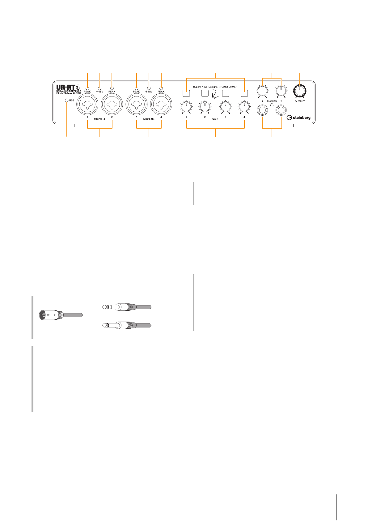
Front Panel UR-RT4
Panel Controls and Terminals
1 [USB] indicator
Lights up when the power is turned on and the unit is
communicating with the computer or iOS device.
The indicator flashes continuously when the computer or
iOS device does not recognize the device.
2 [MIC/HI-Z 1/2] jack
For connection to a microphone, digital instrument,
electric guitar, or electric bass.
This jack can be connected to both XLR-type and phonetype (unbalanced only) plugs. The XLR-type is MIC only
and the phone type is HI-Z only.
3 [MIC/LINE 3/4] jack
For connection to a microphone or digital instrument.
This jack can be connected to both XLR-type and phonetype (balanced/unbalanced) plugs. The XLR type is MIC
only and the phone type is LINE only.
Plug types
4 [PEAK] indicator
Lights up according to the input signal. Lights up when
the input signal is 3 dB below the clipping level.
Setting optimum recording levels
Adjust the gain knobs so that the [PEAK] indicator flashes
briefly at the loudest input volume.
5 [+48V] indicator
Lights up when the [+48V] switch (phantom power) is
turned on.
6 [TRANSFORMER] switch
Switches the transformer circuit of the [MIC/HI-Z 1/2] jack
and [MIC/LINE 3/4] jack on and off.
Use of the [TRANSFORMER] switch
ON (lit)
Passing the input signal through the transformer circuit
results in sound with natural compression and saturation.
OFF (unlit)
This setting results in a well-balanced sound that is faithful
to the original, which is the feature of D-PRE.
Proper use of the HI-Z or LINE inputs
HI-Z
Guitar and bass with passive pickups (not battery
powered)
LINE
• Effect device, preamp, direct box
• Guitar and bass with active pickups (battery powered)
• Digital instruments, such as synthesizer
NOTE
The unit features one transformer of analog circuitry for each front
input channel, created by Rupert Neve Designs® specifically for
audio interface use.
7 [GAIN 1 to 4] knob
Adjusts the input signal level of the [MIC/HI-Z 1/2] jack
and [MIC/LINE 3/4] jack.
UR-RT4 / UR-RT2 Operation Manual 3
Page 4

8 [PHONES 1/2] knob
Adjusts the output signal level of the [PHONES1/2] jack.
9 [PHONES 1/2 ] jack
For connection to a set of stereo headphones.
[PHONES 1] outputs the MIX 1 signals.
[PHONES 2] outputs the MIX 1 or MIX 2 signals. To select
the output signal of the [PHONES 2], refer to “Headphone
Area” (page 14) in the section “dspMixFx UR-RT” or the
“Headphones Window” (page 17) in the section
“Dedicated Windows for Cubase Series.”
What is MIX?
MIX refers to the stereo output signals which flow in the
device. The input signals to the device flow to each MIX.
Refer to the section “Signal Flow” (page 37).
) [OUTPUT] knob
Adjusts the output signal level of the [MAIN OUTPUT]
jacks.
Panel Controls and Terminals
UR-RT4 / UR-RT2 Operation Manual 4
Page 5
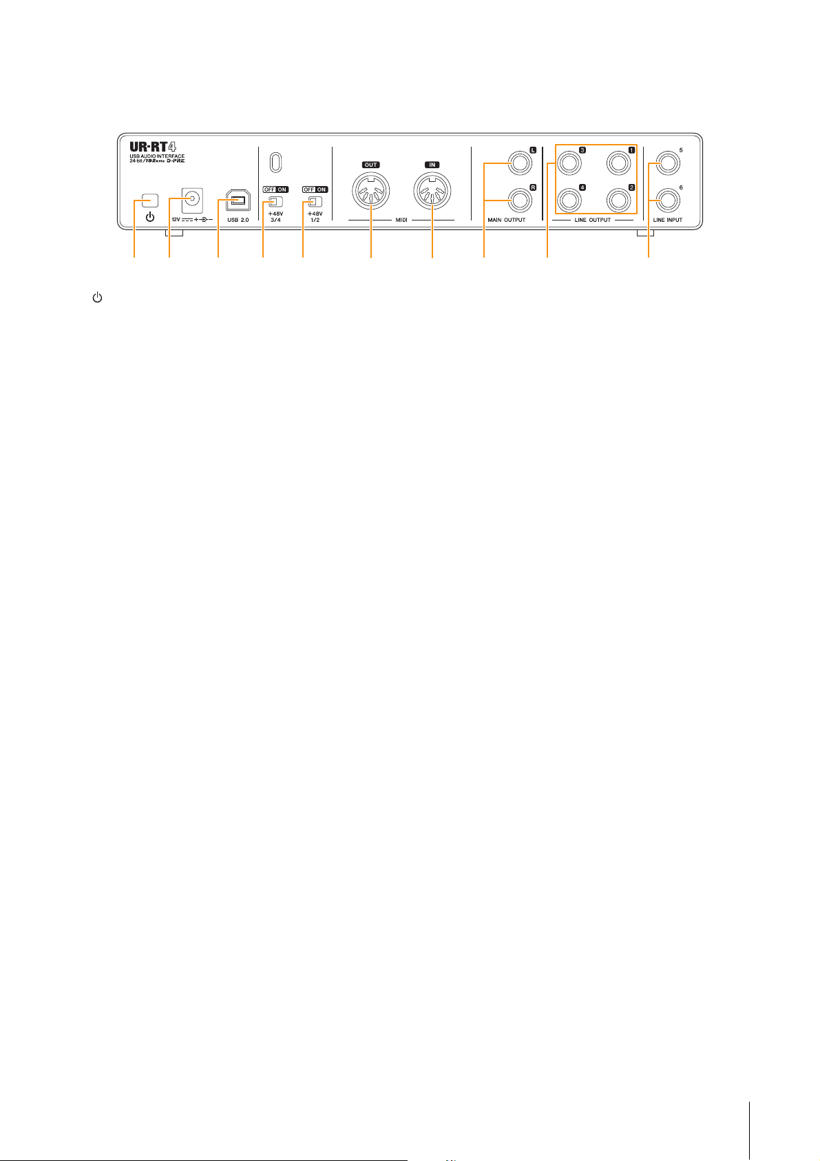
Rear Panel UR-RT4
1 2 6 73 4 5 8 )9
Panel Controls and Terminals
1 [ ](Standby/On) switch
Sets the power of the device to On (
O) or Standby (N).
2 DC IN [12V]
For connection to the AC power adaptor.
3 [USB 2.0] port
For connection to a computer or iOS device.
NOTICE
When connecting to a computer with a [USB 2.0] port,
observe the following to prevent the computer from freezing
or shutting down, as well as corruption or even loss of data.
• USB 3.0 cable requires a separate conversion plug.
• Before connecting/disconnecting the USB cable, be sure to
observe the following points.
-Quit all open software applications on the computer.
-Set all output level controls to the minimum.
• Wait at least six seconds between connecting/
disconnecting the USB cable.
4 [+48V 3/4] switch
Turns the phantom power on and off.
When you turn this switch on, phantom power will be
supplied to the [MIC/LINE 3/4] jack. Turn this switch on
when using a phantom powered condenser microphone.
6 [MIDI OUT] jack
For connection to the MIDI IN jack of the MIDI device.
Transmits MIDI signals from the computer.
7 [MIDI IN] jack
For connection to the MIDI OUT jack of the MIDI device.
Receives and inputs MIDI signals to the computer.
NOTE
Select [Steinberg UR-RT4-port1] for the MIDI port when using a
MIDI jack with an iOS app. Please note that [Steinberg UR-RT4port2] is not available.
8 [MAIN OUTPUT L/R] jacks
For connection to monitor speakers.
These jacks can be connected to phone-type (balanced/
unbalanced) plugs. This outputs the MIX 1 signals. To
adjust the output signal level, use the [OUTPUT] knob on
the front panel.
9 [LINE OUTPUT 1 to 4] jacks
For connection to external devices with line level signals.
These jacks can be connected to phone-type (balanced/
unbalanced) plugs. The [LINE OUTPUT1/2] jack outputs
the MIX 1 signal and the [LINE OUTPUT 3/4] jack outputs
the MIX 2 signal.
5 [+48V 1/2] switch
Turns the phantom power on and off.
When you turn this switch on, phantom power will be
supplied to the [MIC/HI-Z 1/2] jack. Turn this switch on
when using a phantom powered condenser microphone.
NOTICE
When using phantom power, observe the following to prevent
noise and possible damage to UR-RT or connected equipment.
• Do not connect or disconnect any devices while the
phantom power switch is turned to ON.
• Set all output level controls to the minimum before turning
the phantom power switch to ON or OFF.
• When connecting devices not requiring phantom power to
the [MIC/HI-Z 1/2] and [MIC/LINE 3/4] jacks, make sure to set
the phantom power switch to OFF.
NOTE
When the phantom power switch is turned on and off, all inputs/
outputs will be muted for a few seconds.
) [LINE INPUT 5/6] jacks
For connection to digital instrument or a mixer.
These jacks can be connected to phone-type (balanced/
unbalanced) plugs. You can select the input signal level of
the [LINE INPUT 5/6] jacks between “+4 dBu” and “-10
dBV.” Select “+4 dBu” when connecting a professional
audio device, and select “-10 dBV” when connecting a
consumer device. The default initial setting is “-10 dBV.”
To select the input signal level, use the “Setup Window”
(page 14) in the section “dspMixFx UR-RT” or the
“Settings Window” (page 18) in the “Dedicated Windows
for Cubase Series.”
UR-RT4 / UR-RT2 Operation Manual 5
Page 6
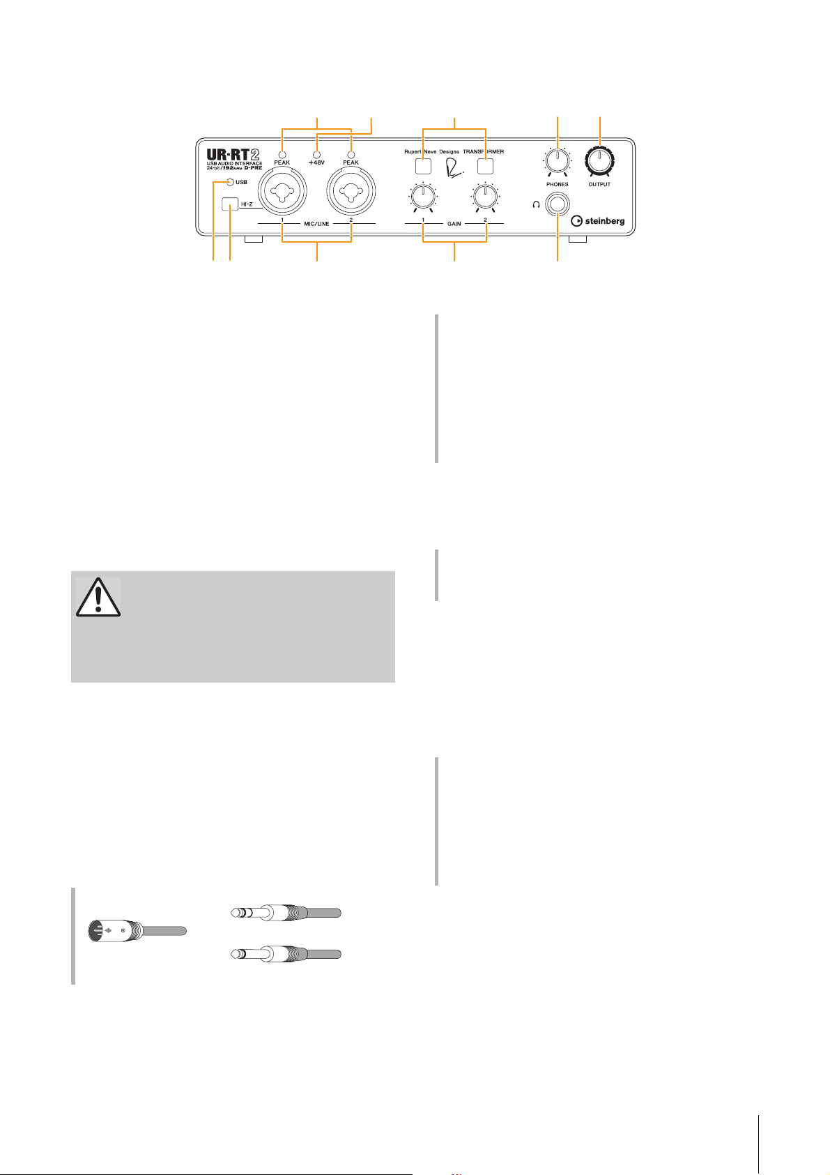
Front Panel UR-RT2
3
8
7
64 )
1 2 9
5
XLR-type (balanced)
Phone-type (balanced)
Phone-type (unbalanced)
1 [USB] indicator
Lights up when the power is turned on and the unit is
communicating with the computer or iOS device.
The indicator flashes continuously when the computer or
iOS device does not recognize the device.
2 [HI-Z] switch
Switches the input impedance (on
Turn this switch on when connecting high impedance
instruments, such as an electric guitar or electric bass,
directly to the [MIC/LINE 1] jack. When you turn this
switch on, use an unbalanced phone plug for connection
between the instruments and the [MIC/LINE 1] jack. If you
use a balanced phone plug, this device will not work
correctly.
CAUTION
To protect your speaker system, leave the monitor
speakers turned off when turning the [HI-Z] switch
on/off. It’s also a good idea to turn all output level
controls down to their minimum. Neglect of these
precautions may result in loud noise bursts that
may damage your equipment, your ears, or both.
O/off N).
Panel Controls and Terminals
Proper use of the HI-Z or LINE inputs
HI-Z
Guitar and bass with passive pickups (not battery
powered)
LINE
• Effect device, preamp, direct box
• Guitar and bass with active pickups (battery powered)
• Digital instruments, such as synthesizer
4 [PEAK] indicator
Lights up according to the input signal. Lights up when
the input signal is 3 dB below the clipping level.
Setting optimum recording levels
Adjust the gain knobs so that the [PEAK] indicator flashes
briefly at the loudest input volume.
5 [+48V] indicator
Lights up when the [+48V] switch (phantom power) is
turned on.
NOTICE
Do not connect or disconnect any cables while turning on the
[HI-Z] switch. Doing so can damage the connected device
and/or the unit itself.
3 [MIC/LINE 1/2] jacks
For connection to a microphone or digital instrument.
This jack can be connected to both XLR-type and phonetype (balanced/unbalanced) plugs. The XLR type is set to
the optimum level for microphone connection and phone
type is for line connection.
Plug types
6 TRANSFORMER switch
Switches the transformer circuit of the [MIC/LINE 1/2] jack
on and off.
Use of the TRANSFORMER switch
ON (lit)
Passing the input signal through the transformer circuit
results in sound with natural compression and saturation.
OFF (unlit)
This setting results in a well-balanced sound that is faithful
to the original, which is the feature of D-PRE.
NOTE
The unit features one transformer of analog circuitry for each front
input channel, created by Rupert Neve Designs® specifically for
audio interface use.
UR-RT4 / UR-RT2 Operation Manual 6
Page 7

7 [GAIN 1/2] knob
Adjusts the input signal level of the [MIC/LINE 1/2] jack.
8 [PHONES] knob
Adjusts the output signal level of the [PHONES] jack.
9 [PHONES ] jack
For connection to a set of stereo headphones.
) [OUTPUT] knob
Adjusts the output signal level of the [MAIN OUTPUT]
jacks.
Panel Controls and Terminals
UR-RT4 / UR-RT2 Operation Manual 7
Page 8
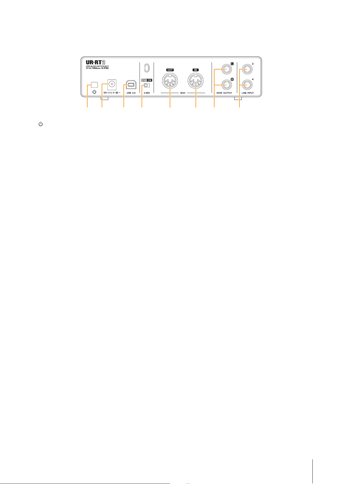
Rear Panel UR-RT2
1 2 5 63 4 7 8
Panel Controls and Terminals
1 [ ](Standby/On) switch
Sets the power of the device to On (
O) or Standby (N).
2 DC IN [12V]
For connection to the AC power adaptor.
3 [USB 2.0] port
For connection to a computer or iOS device.
NOTICE
When connecting to a computer or iOS with a [USB 2.0] port,
observe the following to prevent the computer from freezing
or shutting down, as well as corruption or even loss of data.
• USB 3.0 cable requires a separate conversion plug.
• Before connecting/disconnecting the USB cable, be sure to
observe the following points.
-Quit all open software applications on the computer.
-Set all output level controls to the minimum.
• Wait at least six seconds between connecting/
disconnecting the USB cable.
4 [+48V] switch
Turns the phantom power on and off.
When you turn this switch on, phantom power will be
supplied to the [MIC/LINE 1/2] jack. Turn this switch on
when using a phantom powered condenser microphone.
NOTICE
When using phantom power, observe the following to prevent
noise and possible damage to UR-RT or connected equipment.
• Do not connect or disconnect any devices while the
phantom power switch is turned to ON.
• Set all output level controls to the minimum before turning
the phantom power switch to ON or OFF.
• When connecting devices not requiring phantom power to
the [MIC/HI-Z 1/2] jacks, make sure to set the phantom
power switch to OFF.
NOTE
When the phantom power switch is turned on and off, all inputs/
outputs will be muted for a few seconds.
6 [MIDI IN] jack
For connection to the MIDI OUT jack of the MIDI device.
Receives and inputs MIDI signals to the computer.
NOTE
Select [Steinberg UR-RT2-port1] for the MIDI port when using a
MIDI jack with an iOS app. Please note that [Steinberg UR-RT2port2] is not available.
7 [MAIN OUTPUT L/R] jacks
For connecting to monitor speakers or external devices
with line level signals.
These jacks can be connected to phone-type (balanced/
unbalanced).
8 [LINE INPUT 3/4] jacks
For connection to digital instrument or a mixer.
These jacks can be connected to phone-type (balanced/
unbalanced) plugs. You can select the input signal level of
the [LINE INPUT 3/4] jacks between “+4 dBu” and “-10
dBV.” Select “+4 dBu” when connecting a professional
audio device, and select “-10 dBV” when connecting a
consumer device. The default initial setting is “-10 dBV.”
To select the input signal level, use the “Setup Window”
(page 14) in the section “dspMixFx UR-RT” or the
“Settings Window” (page 18) in the “Dedicated Windows
for Cubase Series.”
5 [MIDI OUT] jack
For connection to the MIDI IN jack of the MIDI device.
Transmits MIDI signals from the computer.
UR-RT4 / UR-RT2 Operation Manual 8
Page 9
Software
1
1
2
3
Software
This section explains software operations for using the
UR-RT with a computer.
Yamaha Steinberg USB Driver
Yamaha Steinberg USB Driver is a software program that
allows communication between the UR-RT and a
computer. In Control Panel, you can configure the basic
settings for the audio driver (Windows) or confirm the
audio driver information (Mac).
How to Open the Window
Windows
• Select [Control Panel] [Hardware and Sound] or
[Sounds, Speech, and Audio Devices] [Yamaha
Steinberg USB Driver]
• From the Cubase series menu, select [Studio] [Studio
Setup] [Yamaha Steinberg USB ASIO] [Control
Panel].
Click the upper tabs to select the desired window.
Mac
• Select [System Preferences] [Yamaha Steinberg USB]
• From the Cubase series menu, select [Studio] [Studio
Setup] [Steinberg UR-RT] [Control Panel] [Open
Config App].
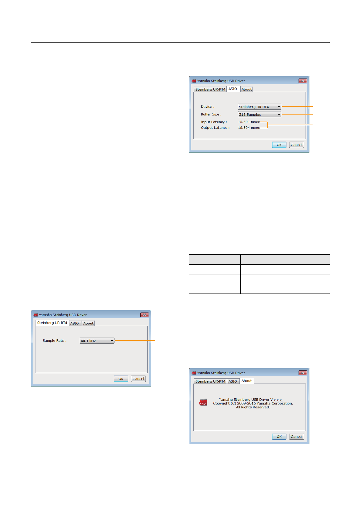
Steinberg UR-RT Window (Windows
only)
This window is for selecting the sample rate.
ASIO Window (Windows only)
For selecting the ASIO driver settings.
1 Device
Lets you select the device for use with the ASIO driver.
This function is available when connecting two or more
devices that are compatible with the Yamaha Steinberg
USB Driver to the computer.
2 Buffer Size
Lets you select the buffer size for the ASIO driver. The
range varies depending on the specified sample rate. The
lower the value of the ASIO buffer size, the lower the value
of audio latency.
Sample Rate Range
44.1 kHz / 48 kHz 64 Samples − 2048 Samples
88.2 kHz / 96 kHz 128 Samples − 4096 Samples
176.4 kHz / 192 kHz 256 Samples − 8192 Samples
3 Input Latency/Output Latency
Indicates the latency (delay time) for the audio input and
output in millisecond units.
1 Sample Rate
Lets you select the sample rate of the device.
Options: 44.1 kHz, 48 kHz, 88.2 kHz, 96 kHz,
176.4 kHz, 192 kHz
NOTE
The available sample rates may differ depending on the particular
DAW you're using.
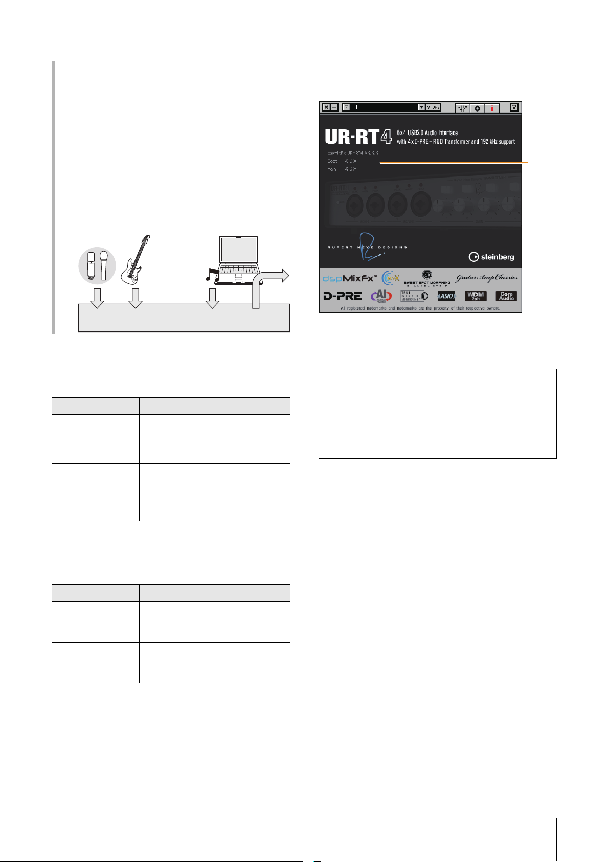
About Window
Indicates the version and copyright information of the
audio driver.
UR-RT4 / UR-RT2 Operation Manual 9
Page 10
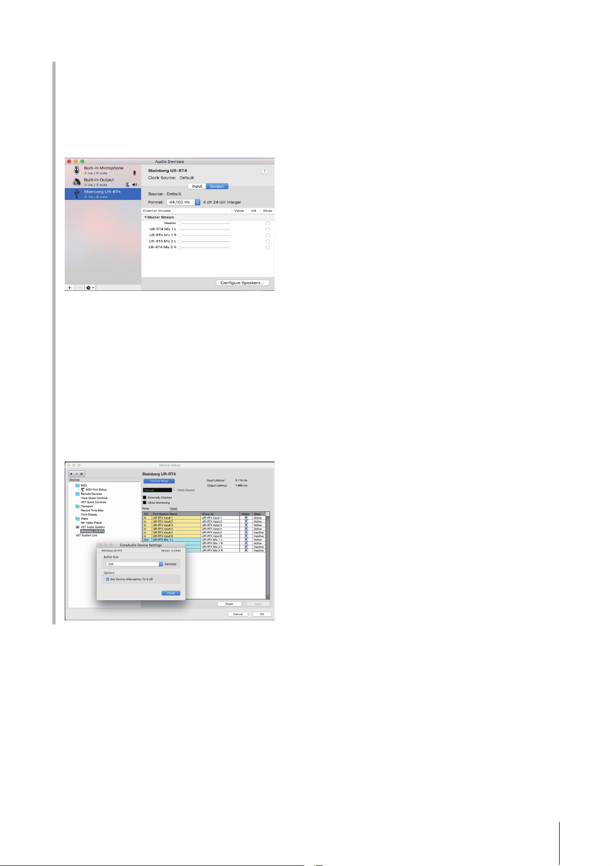
How to Select the Sample Rate (Mac)
You can select the sample rate in [Audio MIDI Setup]
window.
1. Select [Applications] [Utilities] [Audio
MIDI Setup].
2. Select the sample rate from the [Format] menu.
How to Select the Buffer Size (Mac)
You can select the buffer size in the settings window for
each application (DAW software, etc.).
1. From the Cubase series menu, select [Studio]
[Studio Setup].
NOTE
The method for opening the settings window is different
for each application.
Software
2. Click [Control Panel] in [Steinberg UR-RT] in
the menu on the left side of the window.
UR-RT4 / UR-RT2 Operation Manual 10
Page 11
Software
123 5
4 6
7
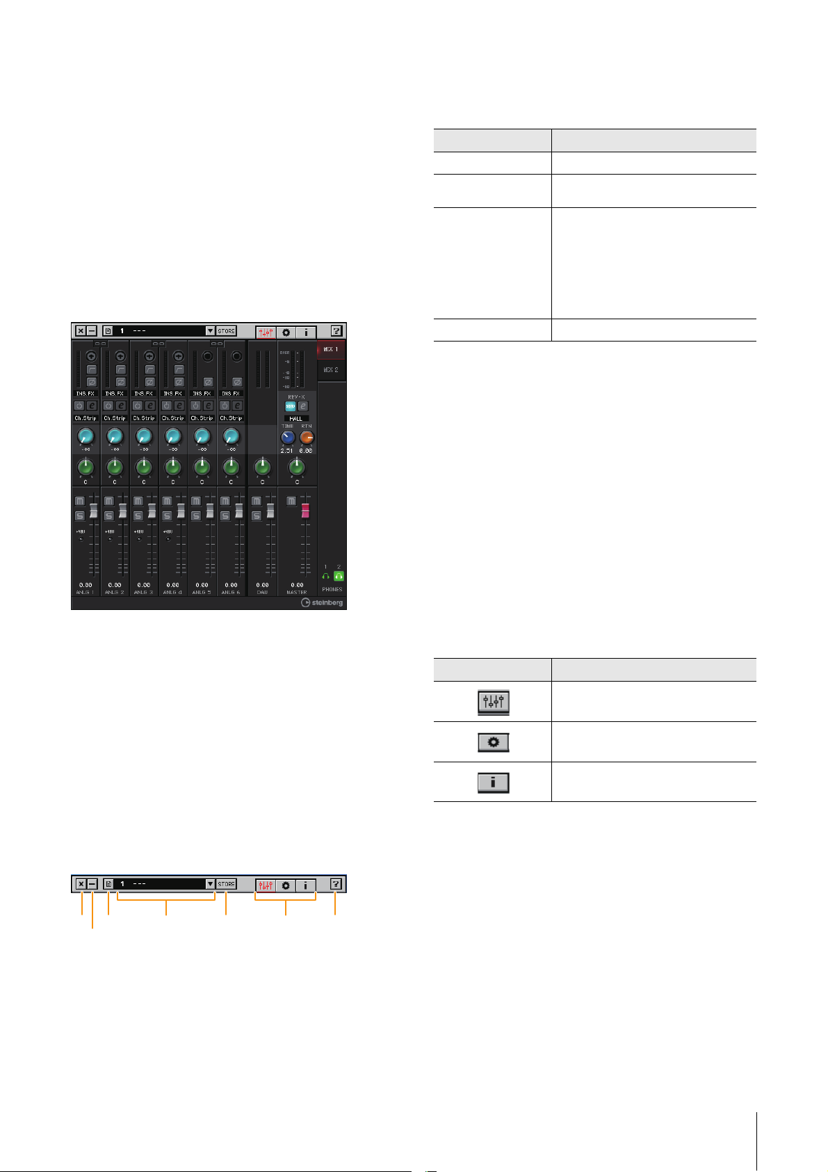
dspMixFx UR-RT
This software is for operating the convenient built-in DSP
mixer and DSP effects. The DSP mixer allows you to mix
up to six input channels {four input channels} down to one
stereo output. A number of DSP effects for processing the
input signals are also provided, and since the processing/
mixing is hardware-based, there is no monitoring latency.
NOTE
You cannot operate dspMixFx UR-RT while a Cubase series DAW is
running. When Cubase is running, configure the DSP mixer and
DSP effect from “Dedicated Windows for Cubase Series” (page 16).
Screenshot
3 Menu
Provides four different menus for various settings.
Menu Description
Open Opens the settings file of dspMixFx UR-RT.
Save Saves the settings file of dspMixFx UR-RT to
Import Scene Imports a scene from the settings file of
Initialize All Scenes Initialize all the saved scenes.
a computer.
dspMixFx UR-RT. Select the desired settings
file of dspMixFx UR-RT and import the
desired scene on the left side of the [IMPORT
SCENE] window. The window appears after
the file is selected in the file selection dialog.
Select the destination for importing on the
right side of the window. Click [OK] to import
it.
4 Scene
Indicates the scene name. You can change the scene
name by clicking on it. Clicking the button on the right
opens the window for calling up other scenes. Call up the
desired scene by clicking it. To cancel calling up the
scene, click outside of the window.
How to Open the Window
Windows
[All Programs] or [All apps] [Steinberg UR-RT]
[dspMixFx UR-RT]
Mac
[Applications] [dspMixFx UR-RT]
Tool A rea
This is the area for configuring the overall common
settings of dspMixFx UR-RT.
5 STORE
Opens the Scene Store window. Enter the desired scene
name into the STORE NAME field. Select the destination
for storing the scene in the No. NAME field. Click [OK] to
store the scene
6 Selecting windows
Selects the desired dspMixFx UR-RT window. The
selected window icon lights in red.
Menu Description
Main window (page 12)
Setup window (page 14)
Information window (page 15)
7 Help
Opens the Operation Manual (this manual).
1 Quit
Quits dspMixFx UR-RT.
2 Minimize
Minimizes the dspMixFx UR-RT window.
UR-RT4 / UR-RT2 Operation Manual 11
Page 12

Software
Channel Area (page 12) MIX Area (page 14)
DAW Area (page 13)
Master Area (page 13)
Headphone Area (page 14)
2
6
5
8
3
1
4
7
$
9
)
!
@
#
Main Window
This window is for configuring the entire signal flow.
3 High Pass Filter
Turns on (lit) and off (unlit) the high pass filter (not
available on [LINE INPUT 5/6] {[LINE INPUT 3/4]}). To
select the cutoff frequency of the high pass filter, use the
“Setup Window” (page 14) in the section “dspMixFx URRT.”
4 Phase
Turns on (lit) and off (unlit) the phase inversion of the
signal.
5 Effect Insertion location
Selects the insertion location of an effect.
Options Description
MON.FX Applies an effect to only the monitor signal
INS.FX Applies an effect to both the monitor signal
(sent to the device).
(sent to the device) and the recording signal
(sent to the DAW software).
6 Effect On/Off
Turns the Effect on (lit) and off (unlit).
Channel Area
This is the area for configuring the input channel settings.
1 Channel Link
Turns on (lit) and off (unlit) the channel link function of two
adjacent channels. When this is on, two mono channels
will become one stereo channel.
2 Level Meter
Indicates the signal level.
7 Effect Edit
Opens (lit) and closes (unlit) the selected effect setup
window.
8 Effect Type
Select the effect type.
Options: ChStrp, Clean, Crnch, Lead, Drive
NOTE
The maximum number of Channel Strip and Guitar Amp Classics
iterations which can be used simultaneously is limited. Refer to the
“Limitations on the use of effects” (page 36).
9 REV-X Send
Adjusts the signal level which is sent to REV-X.
Range: - ∞ dB − +6.00 dB
) Pan
Adjusts the pan.
Range: L16
− C − R16
! Mute
Turns the mute function on (lit) and off (unlit).
@ Solo
Turns the solo function on (lit) and off (unlit).
# +48V
Indicates the on/off status of the phantom power function
of the device.
$ Fader
Adjusts the signal level.
Range: - ∞ dB
− +6.00 dB
UR-RT4 / UR-RT2 Operation Manual 12
Page 13
Software
1
2
3
4
5
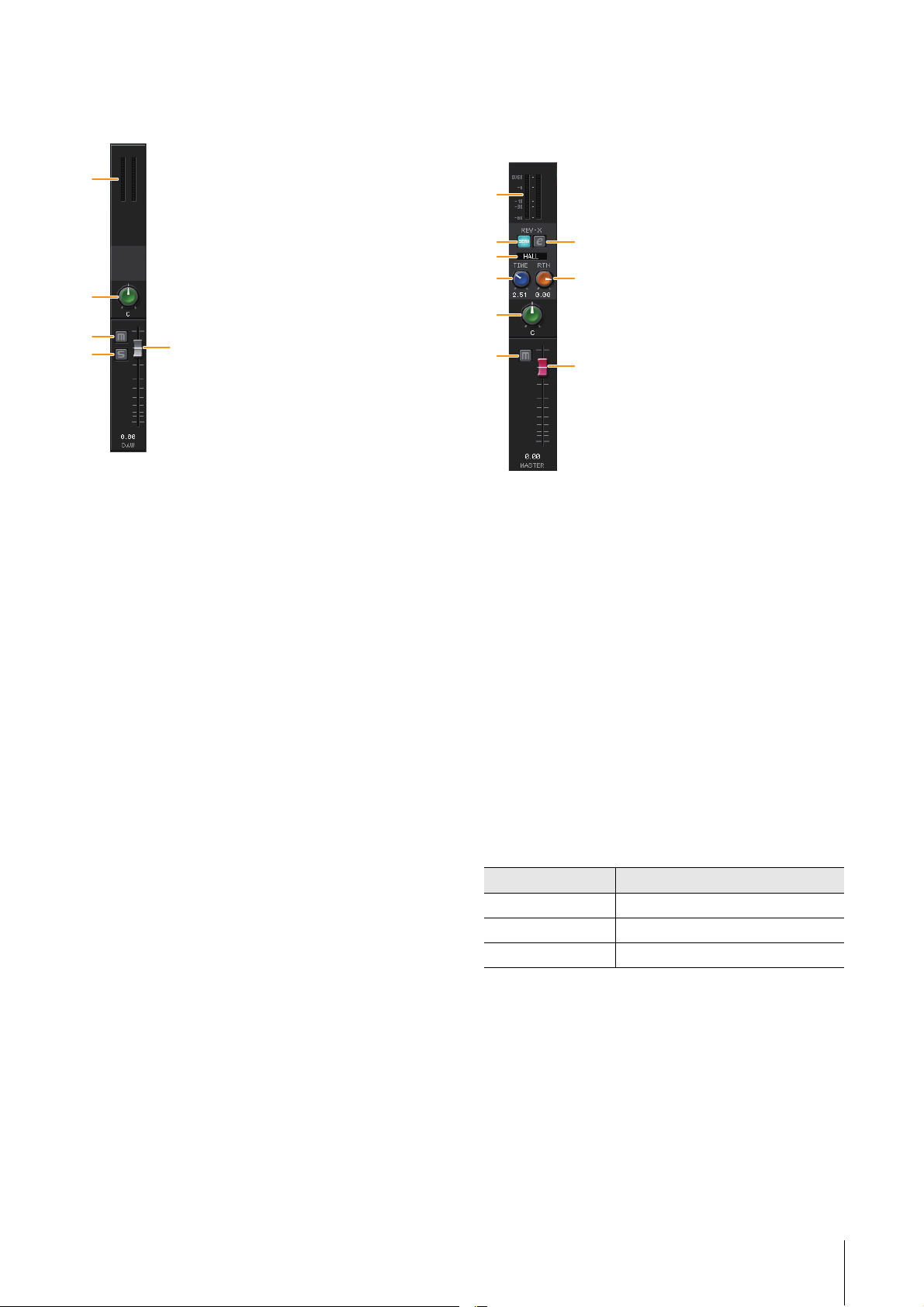
DAW Area
This is the area for configuring the DAW channel settings.
1 Level Meter
Indicates the signal level.
2 Pan
Adjusts the pan.
Range: L16
− C − R16
Master Area
This is the area for configuring the master channel
settings.
1
2
4
5
7
8
1 Level Meter
Indicates the signal level.
2 REV-X Send On
Indicates that REV-X Send is on. This is normally set to on.
3
6
9
3 Mute
Turns the mute function on (lit) and off (unlit).
4 Solo
Turns the solo function on (lit) and off (unlit).
5 Fader
Adjusts the signal level.
Range: - ∞ dB
− +6.00 dB
3 REV-X Edit
Opens (lit) and closes (unlit) the “REV-X” (page 21) setup
window.
4 REV-X Type
Selects the REV-X type.
Options: Hall, Room, Plate
5 REV-X Time
Adjusts the reverb time of REV-X. This parameter links to
Room Size. The adjustable range varies depending on
REV-X type.
REV-X Type Range
Hall 0.103 sec − 31.0 sec
Room 0.152 sec − 45.3 sec
Plate 0.176 sec − 52.0 sec
6 REV-X Return Level
Adjusts the return level of REV-X.
Range: - ∞ dB
− +6.00 dB
7 Pan
Adjusts the pan position
Range: L16
− C − R16
8 Mute
Turn the mute function on (lit)/ off (unlit).
UR-RT4 / UR-RT2 Operation Manual 13
Page 14

Software
1
1
1
2
3
4
5
6
9 Fader
Adjusts the signal level.
Range: - ∞ dB − +6.00 dB
Fader operations
• You can reset certain parameters to 0 dB by double
clicking the fader.
• You can slide all fader channels at the same time by
holding [Ctrl]/[command] and [Shift] while you drag on
the faders.
MIX Area
This is the area for selecting the MIX you want to
configure.
1 MIX
Indicates the MIX object. The UR-RT2 can be set only to
MIX1.
You can copy the Main window settings of the MIX by
dragging and dropping.
Headphone Area
Indicates the monitor signal that is sent from the
[PHONES] jack.
Setup Window
This window is for configuring the common settings of the
device.
1 CONTROL PANEL
For Windows, this opens the “Yamaha Steinberg USB
Driver” (page 9). For Mac, this opens Audio MIDI Setup.
2 INPUT 5/6 LEVEL {INPUT 3/4 LEVEL}
Select the input signal level of [LINE INPUT 5/6] {LINE
INPUT 3/4}.
Options: +4 dBu, -10 dBV
3 HPF
Selects the cutoff frequency of the high pass filter (not
available on [LINE INPUT 5/6]{[LINE INPUT 3/4]}).
Options: 120 Hz, 100 Hz, 80 Hz, 60 Hz, 40 Hz
1 PHONES On/Off
Turns on (lit) and off (unlit) the headphones output. The
UR-RT2 [PHONES 1] is normally on.
You can output the MIX selected in the MIX area to the
PHONES by turning this on.
NOTE
With [PHONES 2], either MIX 1 or MIX 2 can be selected. (UR-RT4
only); [PHONES 1] is fixed to MIX 1 and cannot be changed.
4 LOOPBACK
Turns the Loopback function on (lit) and off (unlit).
UR-RT4 / UR-RT2 Operation Manual 14
Page 15
Software
UR-RT
BGM
Deliver
What is Loopback?
Loopback is a convenient function for broadcasting over
the Internet. It mixes the input audio signals (such as
microphone and guitar) with the audio signals playing
back in the software in the computer into two channels in
the UR-RT, and sends them back to the computer. Refer to
the section “Signal Flow” (page 37).
If the Loopback function is on while you are monitoring
input signals from the UR-RT via DAW software, it will
cause loud noise. This is because an infinite loop of the
audio signal is generated between the UR-RT and the
DAW software. When using the loopback function, turn off
the monitor functions on your DAW software.
5 KNOB MOUSE CONTROL
Selects the method of operating the knobs on dspMixFx
UR-RT.
Options Description
Circular Drag in a circular motion to increase and
Linear Drag in a linear motion to increase and
decrease the parameter. Drag on a dial
clockwise to increase, and counterclockwise
to decrease. If you click any point on the
knob, the parameter will jump there instantly.
decrease the parameter. Drag upward or
rightward to increase, and downward or
leftward to decrease. Even if you click any
point on the knob, the parameter will not
jump there.
Information Window
This window indicates information about dspMixFx UR-RT
and the device.
1
1 Version Information
Indicates the version of the firmware and software.
dspMixFx (for iOS devices)
From your iOS devices, you can conveniently control builtin DSP mixer functions and DSP effects by using
dspMixFx for iOS devices. For details on this app, see the
Steinberg web site below.
http://www.steinberg.net/
6 SLIDER MOUSE CONTROL
Selects the method of operating the sliders and faders on
dspMixFx UR-RT.
Options Description
Jump Click any point on the slider and fader to
Touch Drag the handle of the slider and fader to
increase and decrease the parameter. If you
click any point on the slider and fader, the
parameter will jump there instantly.
increase and decrease the parameter. Even
if you click any point on the slider and fader,
the parameter will not jump there.
UR-RT4 / UR-RT2 Operation Manual 15
Page 16
Dedicated Windows for Cubase Series
These are the windows for configuring the device settings
from Cubase series software. The dedicated windows for
Cubase series allow you to configure the parameters
which are configured by dspMixFx UR-RT. Two types of
windows are available: Input Settings and Hardware
Setup.
Screenshot
Software
1
2
3
4
5
6
7
8
9
)
!
@
#
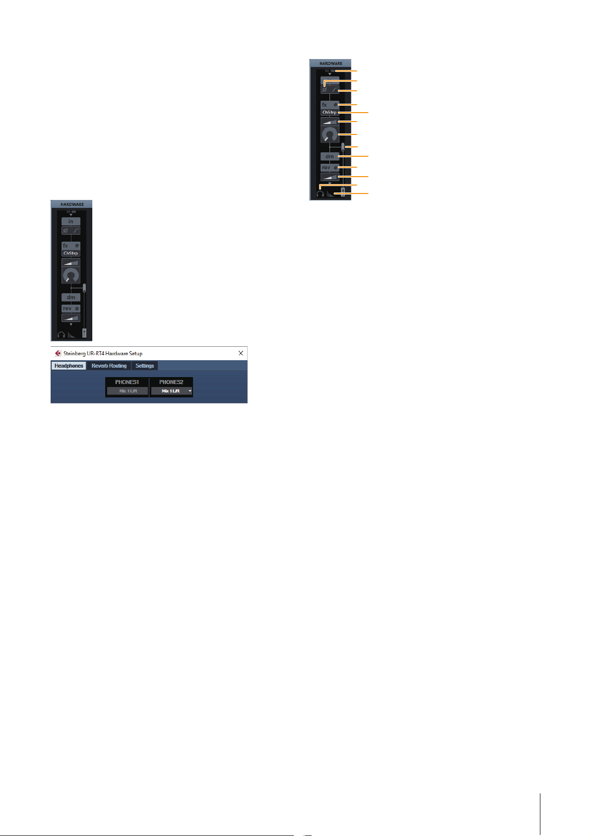
1 +48V
Indicates the phantom power on/off status.
2 Phase
Turns on (lit) and off (unlit) the phase inversion of the
signal.
3 High Pass Filter
Turns on (lit) and off (unlit) the high pass filter (not
available on [LINE INPUT 5/6] {[LINE INPUT 3/4]}). To
select the cutoff frequency of the high pass filter, use the
“Settings Window” (page 18) in the section “Dedicated
Windows for Cubase Series.
How to Open the Window
Input Settings Window
From the Cubase series menu, [Studio] [MixConsole]
[HARDWARE]
Hardware Setup Window
From the Cubase series menu, [Studio] [Audio
Hardware Setup]
Input Settings Window
This window is for configuring the input settings of the
device. The signal flow is from top to bottom. The settings
on this window (except for the +48V indicator) are saved
to the Cubase project file.
Input setting window ([HARDWARE]) is shown according
to the settings for Stereo bus and Mono bus at the UR-RT
device port.
4 Effect Edit
Opens the selected effect setup window.
5 Effect Type
Selects the effect type.
Options: ChStrp, Clean, Crnch, Lead, Drive
NOTE
The maximum number of Channel Strip and Guitar Amp Classics
iterations which can be used simultaneously has restrictions. Refer
to the “Limitations on the use of effects” (page 36).
6 DRIVE/Output Level
When Channel Strip is selected, this adjusts the degree to
which the compressor is applied. The higher the value,
the greater the effect.
Range: 0.00 − 10.00
When Guitar Amp Classics is selected, this adjusts the
output level.
Range: 0.00 − 1.00
7 MORPH
Adjusts the Channel Strip Sweet Spot Data. (Refer to the
“MORPH” in the section “Channel Strip” on page 19).
When Guitar Amp Classics is selected, MORPH is not
displayed.
UR-RT4 / UR-RT2 Operation Manual 16
Page 17

Software
1 2
1 2
3 4 5 6 7
8 Effect Insertion Location
Selects the insertion location of an effect.
Insertion location Description
Upper (OFF) Turns the effect off.
Middle (MON.FX) Applies an effect Strip to only the monitor
Lower (INS.FX) Applies an effect Strip to both the monitor
signal (sent to the device).
signal (sent to the device) and the recording
signal (sent to the DAW software).
9 Output Position of the Direct Monitoring Signal
Indicates the position from which the audio signals for
monitoring will be output when turning on Direct
Monitoring in the device settings on Cubase.
) REV-X Edit
Opens the “REV-X” (page 21) setup window.
! REV-X Send
Adjusts the signal level which is sent to the REV-X.
Range: - ∞ dB − +6.00 dB
@ Headphones Edit
Opens the “Headphones Window” (page 17) in the
section “Dedicated Windows for Cubase Series.”
# Reverb Routing Edit
Opens the “Reverb Routing Window” (page 17) in the
section “Dedicated Windows for Cubase Series.”
Hardware Setup Window
This window is for configuring the general settings of the
device. Click the upper tabs to select the window. Only
the settings on the Reverb Routing window are saved to
the Cubase project file.
Headphones Window (UR-RT4 only)
This window is for configuring the output signal of the
phones settings.
1 PHONES 1
Indicates the output signal of [PHONES 1].
2 PHONES 2
Selects the output signal of [PHONES 2].
Reverb Routing Window
This window is for configuring the “REV-X” (page 21)
settings.
1 REV-X Edit
Opens the “REV-X” (page 21) setup window.
2 REV-X Type
Selects the REV-X type.
Options: Hall, Room, Plate
UR-RT4 / UR-RT2 Operation Manual 17
Page 18

Software
3 REV-X Time
Adjusts the reverb time of REV-X. This parameter links to
Room Size. The adjustable range varies depending on the
REV-X type.
REV-X type Range
Hall 0.103 sec − 31.0 sec
Room 0.152 sec − 45.3 sec
Plate 0.176 sec − 52.0 sec
4 REV-X Send Source Select
Indicates the send source signal which is sent to REV-X.
The UR-RT2 is Mix 1 L/R only.
5 REV-X Send Source
Indicates the signal which is sent to REV-X.
6 REV-X Return Level
Indicates the return level of REV-X.
7 REV-X Return Level Knob
Adjusts the return level of the selected (highlighted)
signal.
Range: - ∞ dB − +6.00 dB
Settings Windows
This window is for configuring the device settings.
1
2
3
1 INPUT 5/6 LEVEL {INPUT 3/4 LEVEL}
Selects the input signal of [LINE INPUT 5/6] {INPUT 3/4
LEVEL}.
Options: +4dBu, -10dBV
2 HPF
Selects the cutoff frequency of the high pass filter (not
available on [LINE INPUT 5/6] { [LINE INPUT 3/4] } ).
Options: 120Hz, 100Hz, 80Hz, 60Hz, 40Hz
3 LOOPBACK
Turns the Loopback function on (lit) and off (unlit).
Refer to the “LOOPBACK” in the section “dspMixFx URRT” (page 15).
UR-RT4 / UR-RT2 Operation Manual 18
Page 19

Software
1 2 43
1
3
2
)
4
5
7
6
8
9
!
Sweet Spot Morphing Channel Strip
The Sweet Spot Morphing Channel Strip (“Channel Strip”
for short) is a multi-effect that combines compression and
EQ. Advanced sound engineering know-how is
condensed into a number of convenient presets that can
be simply and instantly recalled, for professional results.
Four channel strips are provided, and each can be
assigned to the monitor sound only, or to both the monitor
and recorded sound.
The Channel Strip equipped with the device and the
Channel Strip of the VST Plug-in version have the same
parameters. When using the Channel Strip on Cubase
series programs, you can share the settings between the
built-in Channel Strip and the Channel Strip of the VST
Plug-in version as a preset file. When using the built-in
Channel Strip on Cubase series programs, turn on the
[Direct Monitoring] setting in the program. Also, when
assigning the Channel Strip of the VST Plug-in version to
the effect slot on Cubase series programs, select it from
the [Dynamics] category (in the case of the default
settings). Note that you cannot use the built-in Channel
Strip when the sample rate is set to 176.4 kHz or 192 kHz.
Screenshot
Common to Compressor and Equalizer
1 MORPH
Adjusts the parameter of the Sweet Spot Data. You can
simultaneously adjust the compressor and equalizer
settings which are set to five points around this knob by
turning this knob. When you set the knob between two
adjacent points, the compressor and equalizer settings
will be set to an intermediate value.
2 Sweet Spot Data
Selects the Sweet Spot Data.
3 TOTAL GAIN
Adjusts the total gain of the Channel Strip.
Range: -18.0 dB − +18.0 dB
How to Open the Window
From Dedicated Windows for Cubase Series
Select the “Channel Strip” from the “Effect Type”, then
click “Channel Strip Edit” in the section “Input Settings
Window” (page 16).
From dspMixFx UR-RT
Select the “Channel Strip” from the “Effect Type”, then
click “Channel Strip Edit” in the section “Channel Area”
(page 12).
4 Level Meter
Indicates the output level of the Channel Strip.
Compressor
1 AT TACK
Adjusts the attack time of the compressor.
Range: 0.092 msec − 80.00 msec
2 RELEASE
Adjusts the release time of the compressor.
Range: 9.3 msec − 999.0 msec
3 RATIO
Adjusts the release time of the compressor.
Range: 1.00 − ∞
UR-RT4 / UR-RT2 Operation Manual 19
Page 20

Software
1
9
8
7
2
3
4
6
5
4 KNEE
Selects the knee type of the compressor.
Options Description
SOFT Produces the most gradual change.
MEDIUM Results in a setting midway between SOFT
HARD Produces the sharpest change.
and HARD.
5 SIDE CHAIN Q
Adjusts the band width of the side chain filter.
Range: 0.50 - 16.00
6 SIDE CHAIN F
Adjusts the center frequency of the side chain filter.
Range: 20.0 Hz - 20.0 kHz
7 SIDE CHAIN G
Adjusts the gain of the side chain filter.
Range: -18.0 dB − +18.0 dB
8 COMPRESSOR On/Off
Turns the compressor on (lit) and off (unlit).
9 Compressor Curve
This graph indicates the approximate compressor
response.
The vertical axis indicates the output signal level, and the
horizontal axis indicates the input signal level.
2 LOW F
Adjusts the center frequency of the low band.
Range: 20.0 Hz − 1.00 kHz
3 LOW G
Adjusts the gain of the low band.
Range: -18.0 dB − +18.0 dB
4 MID Q
Adjusts the band width of the middle band.
Range: 0.50 − 16.00
5 MID F
Adjusts the center frequency of the middle band.
Range: 20.0 Hz − 20.0 kHz
6 MID G
Adjusts the gain of the middle band.
Range: -18.0 dB − +18.0 dB
7 HIGH F
Adjusts the center frequency of the high band.
Range: 500.0 Hz − 20.0 kHz
8 HIGH G
Adjusts the gain of the high band.
Range: -18.0 dB − +18.0 dB
9 EQUALIZER On/Off
Turns the equalizer on (lit) and off (unlit).
) Gain Reduction Meter
Indicates the gain reduction.
! DRIVE
Adjusts the degree to which the compressor is applied.
The higher the value, the greater the effect.
Range: 0.00 − 10.00
Equalizer
1 Equalizer Curve
This graph indicates the characteristics of the 3-band
equalizer. The vertical axis indicates the gain, and the
horizontal axis indicates the frequency. You can adjust
LOW, MID, and HIGH by dragging each handle in the
graph.
UR-RT4 / UR-RT2 Operation Manual 20
Page 21

Software
1
)
!
REV-X
REV-X is a digital reverb platform developed by Yamaha
for pro audio applications.
One REV-X effect is included in this unit. Input signals can
be sent to the REV-X effect, and the REV-X effect is
applied only to the monitor outputs. Three types of REV-X
are available: Hall, Room, and Plate. The hardware REV-X
equipped with the device and REV-X of the VST Plug-in
version have essentially the same parameters. However,
the [OUTPUT] and [MIX] parameters are only available in
the VST Plug-in version.
When using REV-X on Cubase series programs, you can
share the settings between the built-in REV-X and REV-X
of the VST Plug-in version as a preset file. When using the
built-in REV-X on Cubase series programs, turn on the
[Direct Monitoring] setting in the program. Also, when
assigning REV-X of the VST Plug-in version to the effect
slot on Cubase series programs, select it from the
[Reverb] category (in the case of the default settings).
The built-in REV-X is equipped with an “FX Bus” which is
used for sending the signal from DAW software to REV-X.
For example, to send the recorded audio data to REV-X,
you can check the sound with REV-X, which is used for
monitoring during the recording.
REV-X
−
@
This section uses the Hall type of REV-X as an example.
1 Reverb Time
Adjusts the reverb time.
This parameter links to Room Size. The adjustable range
varies depending on the REV-X type.
# $ %
Screenshot
How to Open the Window
From Dedicated Windows for Cubase Series
• Click “REV-X Edit” (page 17) in the section “Input
Settings Window.”
• Click “REV-X Edit” (page 17) in the section “Reverb
Routing Window.”
From dspMixFx UR-RT
Click “REV-X Edit” (page 13) in the section “Master Area.”
REV-X type Range
Hall 0.103 sec − 31.0 sec
Room 0.152 sec − 45.3 sec
Plate 0.176 sec − 52.0 sec
2 Initial Delay
Adjusts the time that elapses between the direct, original
sound and the initial reflections that follow it
Range: 0.1 msec − 200.0 msec
3 Decay
Adjusts the characteristic of the envelope from the
moment the reverberation starts to the moment it
attenuates and stops.
Range: 0 − 63
4 Room Size
Adjusts the size of the simulated room.
This parameter links to Reverb Time.
Range: 0 − 31
5 Diffusion
Adjusts the spread of the reverberation.
Range: 0 − 10
6 HPF
Adjusts the cutoff frequency of the high pass filter.
Range: 20 Hz − 8.0 kHz
UR-RT4 / UR-RT2 Operation Manual 21
Page 22

7 LPF
Adjusts the cutoff frequency of the low pass filter.
Range: 1.0 kHz − 20.0 kHz
8 Hi Ratio
Adjusts the duration of reverberation in the high frequency
range by using a ratio relative to the Reverb Time. When
you set this parameter to 1, the actual specified Reverb
Time is fully applied to the sound. The lower the value, the
shorter the duration of reverberation in the high frequency
range.
Range: 0.1 − 1.0
9 Low Ratio
Adjusts the duration of reverberation in the low frequency
range by using a ratio relative to the Reverb Time. When
you set this parameter to 1, the actual specified Reverb
Time is fully applied to the sound.
The lower the value, the shorter the duration of
reverberation in the low frequency range.
Range: 0.1 − 1.4
Software
) Low Freq
Adjusts the frequency of the Low Ratio.
Range: 22.0 Hz − 18.0 kHz
! OPEN/CLOSE
Opens and closes the window for adjusting the reverb
settings.
@ Graph
Indicates the characteristics of reverberation. The vertical
axis indicates the signal level, the horizontal axis indicates
the time, and the Z-axis indicates the frequency. You can
adjust the characteristics of reverberation by dragging the
handles in the graph.
# Time Axis Setting
Select the display range of the time (horizontal axis) on
the graph.
Display range: 500 msec − 50 sec
$ Zoom Out
Zooms out the display range of the time (horizontal axis)
on the graph.
% Zoom In
Zooms in the display range of the time (horizontal axis) on
the graph.
Software operation
• You can reset certain parameters to their default values
by holding the [Ctrl]/[command] key while you click on
the appropriate knobs, sliders, and faders.
• You can adjust the parameters more finely by holding the
[SHIFT] key while you drag on the appropriate knobs,
sliders, and faders.
UR-RT4 / UR-RT2 Operation Manual 22
Page 23

Software
65
1 2 3 4 7 8
Guitar Amp Classics
Guitar Amp Classics are guitar amp simulations that make
extensive use of advanced Yamaha modeling technology.
Four amp types with different sonic characteristics are
provided.
The Guitar Amp Classics equipped with the device and
the Guitar Amp Classics of the VST Plug-in version have
the same parameters. When using the Guitar Amp
Classics on Cubase series programs, you can share the
settings between the built-in Guitar Amp Classics and the
Guitar Amp Classics of the VST Plug-in version as a
preset file.
When using the built-in Guitar Amp Classics on Cubase
series programs, turn on the [Direct Monitoring] setting in
the program. Also, when assigning the Guitar Amp
Classics of the VST Plug-in version to the effect slot on
Cubase series programs, select it from the [Distortion]
category (in the case of the default settings).
Note that Guitar Amp Classics cannot be used when the
sample rate is set to 176.4 kHz or 192 kHz.
Screenshot
From dspMixFx UR-RT
Select the “Guitar Amp Classics” from the “Effect Type”,
then click “Effect Edit” in the section “Channel Area”
(page 12).
CLEAN
This amp type is optimized for clean tones, effectively
simulating the tight brilliance of transistor amplifiers. The
tonal character of this amp model provides an ideal
platform for recording with multi-effects. It also features
built-in chorus and vibrato effects.
1 VOLUME
Adjusts the amplifier’s input level.
How to Open the Window
From Dedicated Windows for Cubase Series
Select the “Guitar Amp Classics” from the “Effect Type”,
then click “Effect Edit” in the section “Input Settings
Window” (page 16).
2 DISTORTION
Adjusts the depth of distortion produced.
3 TREBLE/MIDDLE/BASS
These three controls adjusts the amplifier’s tonal response
in the high, middle, and low frequency ranges.
4 PRESENCE
Can be adjusted to emphasize the high frequencies and
overtones.
5 Cho/OFF/Vib
Turns the Chorus or Vibrato effect on or off. Set to [Cho] to
turn the Chorus effect on, or to [Vib] to turn the Vibrato
effect on.
6 SPEED/DEPTH
These controls adjust the speed and depth of the Vibrato
effect when it is on. The SPEED and DEPTH controls only
work with the Vibrato effect, and are disengaged when the
Cho/OFF/Vib control, above, is set to “Cho” or “OFF.
7 BLEND
Adjusts the balance between the direct and effect sound.
8 OUTPUT
Adjusts the final output level.
UR-RT4 / UR-RT2 Operation Manual 23
Page 24

Software
1 2 3 4 5
1 2 3 4 5 6
1 2 3 4 5 6
CRUNCH
This is the amp type to use when you want lightly
overdriven crunch tones. The CRUNCH model simulates
the type of vintage tube amplifiers that are favored for
blues, rock, soul, R&B, and similar styles.
1 Normal/Bright
Selects a normal or bright tonal character.
The [Bright] setting emphasizes the high-frequency
overtones.
2 GAIN
Adjusts the input level applied to the preamp stage.
Rotate clockwise to increase the amount of overdrive
produced.
3 TREBLE/MIDDLE/BASS
These three controls adjust the amplifier’s tonal response
in the high, middle, and low frequency ranges.
1 AMP TYPE
Six amplifier types are provided. Types 1 and 2 feature
relatively mild distortion that allows picking nuances to
come through naturally. Types 3 and 4 have more
pronounced overtones, resulting in a fat, soft tone. Types
5 and 6 deliver wilder, aggressive distortion with a tight
attack. The even-numbered amp types have greater
presence and range than the odd-numbered types.
2 GAIN
Adjusts the input level applied to the preamp stage.
Rotate clockwise to increase the amount of distortion
produced
3 MASTER
Adjusts the output level from the preamp stage.
4 TREBLE/MIDDLE/BASS
These three controls adjust the amplifier’s tonal response
in the high, middle, and low frequency ranges.
5 PRESENCE
Can be adjusted to emphasize the high frequencies and
overtones.
6 OUTPUT
Adjusts the final output level
4 PRESENCE
Can be adjusted to emphasize the high frequencies and
overtones.
5 OUTPUT
Adjusts the final output level.
DRIVE
The DRIVE amp type provides a selection of distortion
sounds that simulate the tonal character of various
highgain tube amplifiers. From mildly overdriven crunch to
heavy distortion suitable for hard rock, heavy metal, or
hardcore styles, this model offers a wide range of sonic
capabilities.
LEAD
The LEAD amp type simulates a high-gain tube amp that
is rich in overtones. It is ideally suited to playing lead
guitar lines that will project well in an ensemble, but it can
also be set up for crisp accompaniment tones as well.
1 High/Low
Selects the amp output type.
The [High] setting simulates a high-output amp, and
allows the creation of more distorted tones.
2 GAIN
Adjusts the input level applied to the preamp stage.
Rotate clockwise to increase the amount of distortion
produced.
3 MASTER
Adjusts the output level from the preamp stage.
4 TREBLE/MIDDLE/BASS
These three controls adjust the amplifier’s tonal response
in the high, middle, and low frequency ranges.
UR-RT4 / UR-RT2 Operation Manual 24
Page 25

5 PRESENCE
Used to emphasize the high frequencies and overtones.
6 OUTPUT
Adjusts the final output level.
Using the GAIN, MASTER, and OUTPUT Controls
The tonal character of the DRIVE and LEAD amp types can
be adjusted over a wide range via the GAIN, MASTER, and
OUTPUT controls. GAIN adjusts the level of the signal
applied to the preamp stage, affecting the amount of
distortion produced. MASTER adjusts the output level from
the preamp stage that is then fed to power amp stage. The
GAIN and MASTER control settings have a large effect on
the final sound, and the MASTER control may need to be
turned up fairly high in order to drive the power stage
sufficiently for optimum tone. The OUTPUT control adjusts
the final output level from the amp model without affecting
the distortion or tone, and is useful for adjusting the guitar’s
volume without changing any other aspects of the sound.
Software
UR-RT4 / UR-RT2 Operation Manual 25
Page 26

Using with a Computer
Computer
Synthesizer/MIDI keyboard
Monitor speakers Outboard
Headphone
amp
Microphone Guitar
Keyboard
Headphones
Rear panel
Front panel
Mixer
When using the
condenser microphone,
turn the switch on
after connecting it.
(Turn the switch off
before disconnecting it.)
Check!
Set all volume levels to
minimum before connecting
or disconnecting
the external device.
Check!
Connection Example UR-RT4
Using with a Computer
UR-RT4 / UR-RT2 Operation Manual 26
Page 27

Connection Example UR-RT2
Set all volume levels to minimum
before connecting or disconnecting
the external device.
Check!
Computer
Synthesizer/MIDI keyboard
Monitor speakers
Headphones
Rear panel
Front panel
Microphone Guitar
Keyboard
Mixer
When using the
condenser microphone,
turn the switch on
after connecting it.
(Turn the switch off
before disconnecting it.)
Check!
Using with a Computer
UR-RT4 / UR-RT2 Operation Manual
27
Page 28

Using with a Computer
Configuring Audio Driver Settings on the DAW Software
Cubase Series Programs
1. Make sure that all applications have been closed.
2. Make sure that the [ ] switch has been turned
on (
O).
3. Double-click the shortcut of Cubase series on the
desktop to start Cubase.
4. When the [ASIO Driver Setup] window appears
while the Cubase series program is launching,
confirm that the device is selected, then click
[OK].
The audio driver settings are now complete.
Programs other than Cubase Series
1. Make sure that all applications have been closed.
Recording/Playback
This section explains simple recording operations for
using a microphone. Connect a microphone as shown in
the connection examples (pages 26, 27). Turn the [+48V]
switch on when using a phantom powered condenser
microphone.
Cubase Series Programs
1. Launch the Cubase series DAW.
The [steinberg hub] window appears.
2. Select the project template [Steinberg UR-RT
Vocal-Inst Recording 1-C7] in [Recording] on the
[steinberg hub] window, then click [Create].
3. Turn on Direct Monitoring as follows.
[Studio] [Studio Setup] [Yamaha Steinberg USB
ASIO](Windows) or [Steinberg UR-RT](Mac)
checkmark to [Direct Monitoring]
[OK]
enter
2. Make sure that the [ ] switch has been turned
on (
O).
3. Launch the DAW software.
4. Open the audio interface settings window.
5. (Windows only) Select the ASIO Driver for the
audio driver settings.
6. Set the ASIO Driver for Windows and audio
interface for Mac as follows
Windows
Set the [Yamaha Steinberg USB ASIO] to the ASIO Driver
settings.
Mac
Set the UR-RT to the audio interface settings.
The audio driver settings are now complete.
4. Confirm that the [Record Enable] and [Monitor]
indicators are turned on (lit) for the audio track.
5. While singing into the microphone, adjust the
input signal level of the microphone with the
[GAIN] knob on the device.
Setting optimum recording levels
Adjust the gain knobs so that the [PEAK] indicator flashes
briefly at the loudest input volume.
6. While singing into the microphone, adjust the
output signal level of the headphones with the
[PHONES] knob on the device.
7. Set the Channel Strip settings and REV-X
settings on the Input Settings window.
Select the Channel Strip Insertion location depending
on the desired insert point. The default setting is
“Lower” (applied to both the monitor signal and the
recording signal). For details on the Insertion location,
refer to the “Effect Insertion location” (page 17) in the
section “Dedicated Windows for Cubase Series.”
UR-RT4 / UR-RT2 Operation Manual 28
Page 29

8. Click [I] to start the recording.
Using with a Computer
Programs Other Than Cubase Series
1. Launch your DAW software.
2. Open dspMixFx UR-RT.
For instructions on how to open dspMixFx UR-RT, refer
to the section “How to Open the Window” (page 11).
3. Adjust the input signal level of the microphone
with the [GAIN] knob on the device.
Setting optimum recording levels
Adjust the gain knobs so that the [PEAK] indicator flashes
briefly at the loudest input volume.
4. While singing into the microphone, adjust the
output signal level of the headphones with the
[PHONES] knob on the device.
9. After finishing the recording, click [J] to stop it.
10. Turn [Monitor] off (unlit) for the just recorded
audio track.
11. Click the Ruler to move the project cursor to the
desired point for starting playback.
12. Click [R] to check the recorded sound.
When listening to the sound over monitor speakers,
adjust the output signal level by the [OUTPUT] knob on
the device.
5. Set the Channel Strip settings and REV-X
settings on dspMixFx UR-RT.
6. Start recording on your DAW software.
7. After finishing recording, stop it.
8. Playback the newly recorded sound to check it.
For more detailed instructions on using the DAW software,
refer to your particular DAW’s software manual.
The recording and playback operations are now
complete.
For more detailed instructions on using Cubase series
programs, refer to the PDF manual, available from [Help]
in the Cubase series menu.
UR-RT4 / UR-RT2 Operation Manual
29
Page 30

Using with an iOS device
Set all volume levels to
minimum before connecting or
disconnecting
the external device.
Check!
When using the
condenser microphone,
turn the switch on
after connecting it.
(Turn the switch off
before disconnecting it.)
Check!
iPad
Apple iPad
Camera
Connection Kit/
Lightning to
USB Camera
Adapter
iPhone
Synthesizer/MIDI keyboard
Monitor speakers Outboard
Headphone
amp
Microphone Guitar
Keyboard
Headphones
Rear panel
Front panel
Mixer
Connection Example UR-RT4
Using with an iOS device
NOTE
• AppleiPadCameraConnectionKitorLightningtoUSBCameraAdapterarerequiredwhenconnectingtheUR-RTwithan
iOSdevice.
• ForthelatestinformationoncompatibleiOSdevices,refertotheSteinbergWebsitebelow.
http://www.steinberg.net/
UR-RT4 / UR-RT2 Operation Manual 30
Page 31

Connection Example UR-RT2
Set all volume levels to minimum
before connecting or disconnecting
the external device.
Check!
Synthesizer/MIDI keyboard
Monitor speakers
Headphones
Rear panel
Front panel
Microphone Guitar
Keyboard
Mixer
When using the
condenser microphone,
turn the switch on
after connecting it.
(Turn the switch off
before disconnecting it.)
Check!
iPad
Apple iPad Camera
Connection Kit/
Lightning to
USB Camera Adapter
iPhone
Using with an iOS device
NOTE
• AppleiPadCameraConnectionKitorLightningtoUSBCameraAdapterarerequiredwhenconnectingtheUR-RTwithan
iOSdevice.
• ForthelatestinformationoncompatibleiOSdevices,refertotheSteinbergWebsitebelow.
http://www.steinberg.net/
UR-RT4 / UR-RT2 Operation Manual
31
Page 32

Using with an iOS device
Recording/Playback
This section covers basic instructions for operating with
Cubasis (an iPad app sold by Apple).
NOTE
• iOSappmaynotbesupportedinyourarea.Pleasecheck
withyourYamahadealer.
• ForthelatestCubasisinformation,seetheSteinbergweb
sitebelow.
http://www.steinberg.net/
1. Open Cubasis.
2. Tap the [MEDIA] tab on the upper left of the
screen.
[Create New Project] is shown in the bottom of the
screen.
6. Tap on the far left of your screen to show the
track menu, with [Audio input] at the top.
7. Tap to show the details window and set the
input bus for the track by tapping a number.
3. Tap the [Create New Project].
4. Enter a project name and tap [OK] in the [New
project] window.
5. Tap [+AUDIO] to add an AUDIO track.
8. Tap to turn monitoring on (lit).
9. Adjust the input signal level of the microphone
with the [GAIN] knob on the device.
Setting optimum recording levels
Adjust the gain knobs so that the [PEAK] indicator flashes
briefly at the loudest input volume.
10. While singing into the microphone, adjust the
output signal level of the headphones with the
[PHONES] knob on the device.
11. Ta p [I] to start the recording.
12. Tap [>] to stop the recording.
UR-RT4 / UR-RT2 Operation Manual 32
Page 33

13. Tap and slide on the ruler to move the playback
position.
You can also tap to return the beginning of the
recording.
14. Tap [>] to playback the recorded sound.
dspMixFx (for iOS devices)
From your iOS devices, you can conveniently control builtin DSP mixer functions and DSP effects by using
dspMixFx for iOS devices. For details on this app, see the
Steinberg web site below.
http://www.steinberg.net/
Using with an iOS device
UR-RT4 / UR-RT2 Operation Manual
33
Page 34

Troubleshooting
Troubleshooting
Power does not turn on.
(The USB indicator is off or
flashing continuously, even
though the UR-RT is
connected to a computer or
iOS device.)
No Sound
Has the TOOLS for UR-RT been installed properly?
Refer to the Startup Guide instructions to complete the TOOLS for UR-RT
installation.
Is the AC adaptor connected correctly?
The UR-RT is not a bus-powered type device. Refer to the Startup Guide
instructions to turn on the [ ] switch.
Confirm whether or not a proper USB cable is used.
If the USB cable is broken or damaged, replace the USB cable with a new one.
Make sure to use a USB cable no longer than 3 meters.
Has TOOLS for UR-RT been installed properly?
Refer to the Startup Guide instructions to complete the TOOLS for UR-RT
installation.
Confirm whether or not a proper USB cable is used.
If the USB cable is broken or damaged, replace the USB cable with a new one.
Make sure to use a USB cable no longer than 3 meters.
Are the volume controls of the device set to appropriate levels?
Confirm the levels of the [OUTPUT] knob and [PHONES] knob.
Are the microphones and monitor speakers connected to the device
properly?
Refer to the section “Connection Examples” (pages 26, 27, 30, 31) to confirm the
connection.
Are the audio driver settings on DAW software set properly?
Refer to the section “Configuring the Audio Driver Settings on DAW Software”
(page 28) to set it.
Is the [ASIO Driver] setting on the Cubase series program set
properly?
From the Cubase series menu, open the [Studio] [Studio Setup] [VST Audio
System], then confirm that the [Yamaha Steinberg USB ASIO] (Windows) or
[Steinberg UR-RT] (Mac) is selected on the [ASIO Driver].
Windows Mac
UR-RT4 / UR-RT2 Operation Manual 34
Page 35

Troubleshooting
No sound
Unusual sound
(noise, interruption, or
distortion)
Was the power of the device turned on before starting the DAW
software?
Before starting the DAW software, connect the device to a computer and turn on
the power of the device.
Is the monitor speaker switch turned on?
Confirm that the monitor speaker switch is turned on.
Is the buffer size set too low?
Increase the buffer size compared to the current settings; refer to the section
“Yamaha Steinberg USB Driver” (page 9) for instructions.
Does your computer satisfy the system requirements?
Confirm the system requirements. For the latest information, see the Steinberg
website below.
http://www.steinberg.net/
Are you recording or playing long continuous sections of audio?
The audio data processing capabilities of your computer will depend on a
number of factors including CPU speed and access to external devices. Reduce
the audio tracks and check the sound again.
Are the microphones properly connected to the device?
Connect a microphone with an XLR plug to the device. If you use a phone plug,
the volume may be insufficient.
Is the loopback function set properly?
Set Enable Loopback to off when not using the Loopback function. For
instructions, refer to the section “Settings Window” (page 18) or “Setup Window”
(page 14).
For the latest support information, refer to the Steinberg website below.
http://www.steinberg.net/
UR-RT4 / UR-RT2 Operation Manual
35
Page 36

Appendix
Appendix
Limitations on the use of effects
The maximum number of Channel Strip and Guitar Amp Classics iterations which can be used simultaneously are limited to
the following. For example, Channel Strip can be used for two mono channels, while Guitar Amp Classics can be used for
one mono channel simultaneously.
Channel Strip Guitar Amp Classics
Mono Stereo Mono Stereo
400-
210-
201-
020-
011-
UR-RT4 / UR-RT2 Operation Manual 36
Page 37

Appendix
Lower (MON.FX)
To DAW
input
Ch. Strip
From input on the device
To output on the device
To DAW
input
From input on the device
To output on the device
Upper (INS.FX)
From input on the device
To output on the device
To DAW
input
Ch. Strip
Not applied (OFF)
Signal Flows
The following chart indicates the signal flow in the device.
NOTE
• The controllers on the device, such as the [GAIN] knob, [OUTPUT] knob are not included in this chart.
• To configure each parameter, use the “dspMixFx UR-RT” (page 11) or “Dedicated Windows for Cubase Series” (page 16).
• Please note that you cannot use the built-in Channel Strip (Ch. Strip) and Guitar Amp Classics when the sample rate is set to 176.4 kHz or
192 kHz.
UR-RT4
From
[MIC/HI-Z 1]
Ch. Strip
*1
Ch. Strip
REV-X
Send
Level
From
[MIC/HI-Z 2]
Ch. Strip
Ch. Strip
REV-X select
REV-X
Send
Level
From
[LINE INPUT 6]
Ch. Strip
Ch. Strip
MIX 1
MIX 2
*2
REV-X
Send
Level
-X
REV-X
From
[MIDI IN]
REV-X
Return
Level
To
[MIDI OUT]
REV-X
Return
Level
LOOPBACK OFF/ON
To DAW input
USB
From
DAW output
To [PHONES 1]
To [MAIN OUTPUT]
To [LINE OUTPUT 1/2]
To [LINE OUTPUT 3/4]
To [PHONES 2]
OUTPUT SELECT
*1 The following chart indicates an effect insertion location.
*2 You can turn this on for either MIX 1 or MIX 2.
UR-RT4 / UR-RT2 Operation Manual 37
Page 38

UR-RT2
*1
MIX 1
LOOPBACK OFF/ON
To DAW input
REV-X
Ch. Strip
Ch. Strip
Ch. Strip
Ch. Strip
Ch. Strip
Ch. Strip
REV-X
Send
Level
REV-X
Send
Level
REV-X
Send
Level
REV-X
Return
Level
To
[MIDI OUT]
From
[MIC/LINE 1]
From
[MIC/LINE 2]
From
[MIDI IN]
From
[LINE INPUT 4]
From
DAW output
To [MAIN OUTPUT 1/2]
To [PHONES 1]
USB
Lower (MON.FX)
To DAW
input
Ch. Strip
From input on the device
To output on the device
To DAW
input
From input on the device
To output on the device
Upper (INS.FX)
From input on the device
To output on the device
To DAW
input
Ch. Strip
Not applied (OFF)
Appendix
*1 The following chart indicates an effect insertion location.
UR-RT4 / UR-RT2 Operation Manual 38
Page 39

Block Diagrams
Φ
Φ
Φ
〜
〜
〜
〜
TRANSFORMER
TRANSFORMER
UR-RT4 – 44.1/48/88.2/96 kHz
Appendix
UR-RT4 / UR-RT2 Operation Manual 39
Page 40

UR-RT4 – 176.4/192 kHz
Φ
Φ
Φ
〜
〜
〜
〜
TRANSFORMER
TRANSFORMER
Appendix
UR-RT4 / UR-RT2 Operation Manual 40
Page 41

UR-RT4 – 44.1/48/88.2/96 kHz – iOS device
Φ
Φ
Φ
〜
〜
〜
〜
TRANSFORMER
TRANSFORMER
Appendix
UR-RT4 / UR-RT2 Operation Manual 41
Page 42

UR-RT4 – 176.4/192 kHz – iOS device
Φ
Φ
Φ
〜
〜
〜
〜
TRANSFORMER
TRANSFORMER
Appendix
UR-RT4 / UR-RT2 Operation Manual 42
Page 43

UR-RT2 – 44.1/48/88.2/96 kHz
Appendix
〜
Φ
TRANSFORMER
〜
〜
〜
Φ
TRANSFORMER
〜
Φ
UR-RT4 / UR-RT2 Operation Manual 43
Page 44

UR-RT2 – 176.4/192 kHz
Appendix
〜
Φ
TRANSFORMER
〜
〜
〜
Φ
TRANSFORMER
〜
Φ
UR-RT4 / UR-RT2 Operation Manual 44
Page 45

UR-RT2 – 44.1/48/88.2/96 kHz – iOS device
Φ
Φ
〜
〜
〜
〜
〜
Φ
TRANSFORMER
TRANSFORMER
Appendix
UR-RT4 / UR-RT2 Operation Manual 45
Page 46

UR-RT2 – 176.4/192 kHz – iOS device
Φ
Φ
〜
〜
〜
〜
〜
Φ
TRANSFORMER
TRANSFORMER
Appendix
UR-RT4 / UR-RT2 Operation Manual 46
Page 47

General Specifications
UR-RT4
Power Requirements 18 W
Dimensions (W × H × D) 267 × 47 × 208 mm
Net Weight 2.4 kg
Appendix
Operating Free-air Temperature
Range
Included Accessories
0 − 40 °C
- AC adaptor (PA-150B or equivalent)
- TOOLS for UR-RT4 CD-ROM
- Startup Guide (brochure)
- CUBASE AI DOWNLOAD INFORMATION (printed)
- ESSENTIAL PRODUCT LICENCE INFORMATION (printed)
- USB cable
UR-RT2
Power Requirements 18 W
Dimensions (W × H × D) 198 × 47 × 208 mm
Net Weight 1.7 kg
Operating Free-air Temperature
Range
Included Accessories
0 − 40 °C
- AC adaptor (PA-150B or equivalent)
- TOOLS for UR-RT2 CD-ROM
- Startup Guide (brochure)
- CUBASE AI DOWNLOAD INFORMATION (printed)
- ESSENTIAL PRODUCT LICENCE INFORMATION (printed)
- USB cable
The contents of this manual apply to the latest specifications as of the publishing date.
To obtain the latest manual, access the Steinberg website then download the manual file.
UR-RT4 / UR-RT2 Operation Manual 47
Page 48

Technical Specifications
UR-RT4
MIC INPUT 1-4 (balanced)*
Frequency Response +0.1/-0.3 dB, 20 Hz to 22 kHz
Dynamic Range 101 dB, A-Weighted
THD+N 0.0035 %, 1 kHz, -3 dBFS, 22 Hz/22 kHz BPF
Maximum Input Level +4 dBu
Input Impedance 4 kΩ
Gain Range +6 dB − +60 dB
HI-Z INPUT 1/2 (unbalanced)
Maximum Input Level +8.5 dBV
Input Impedance 1 MΩ
Gain Range -0.7 dB − +53.3 dB
LINE INPUT 3/4 (balanced)
Maximum Input Level +24 dBu
Input Impedance 20 kΩ
Gain Range -14 dB − +40 dB
LINE INPUT 5/6 (balanced/unbalanced)
Frequency Response +0.1/-0.1 dB, 20 Hz to 22 kHz
Dynamic Range 102 dB, A-Weighted
THD+N 0.0025 %, 1 kHz, -3 dBFS, 22 Hz/22 kHz BPF
Maximum Input Level +22 dBu (+4 dBu input), +2.1 dBV (-10 dBV input)
Input Impedance 30 kΩ (+4 dBu input) / 20 kΩ (-10 dBV input)
Gain Selection +4 dBu or -10 dBV input Switchable
LINE OUTPUT 1-4 (balanced/unbalanced)
Frequency Response +0.1/-0.1 dB, 20 Hz to 22 kHz
Dynamic Range 114 dB, A-Weighted
THD+N 0.0015 %, 1 kHz, -3 dBFS, 22 Hz/22 kHz BPF
Maximum Output Level +16 dBu
Output Impedance 75 Ω
MAIN OUTPUT (balanced/unbalanced)
Frequency Response +0.1/-0.1 dB, 20 Hz to 22 kHz
Dynamic Range 114 dB, A-Weighted
THD+N 0.0015 %, 1 kHz, -3 dBFS, 22 Hz/22 kHz BPF
Maximum Output Level +16 dBu
Output Impedance 75 Ω
PHONES 1/2
Maximum Output Level 100 mW+ 100 mW, 40 Ω
USB
Specification USB2.0, 24-bit, 44.1 kHz/48 kHz/88.2 kHz/96 kHz/176.4 kHz/192 kHz
XLR INPUT
Polarity 1: Ground,
2: Hot (+),
3: Cold (-)
Appendix
*[TRANSFORMER]switchOFF
UR-RT4 / UR-RT2 Operation Manual 48
Page 49

UR-RT2
MIC INPUT 1/2 (balanced)*
Frequency Response +0.1/-0.3 dB, 20 Hz to 22 kHz
Dynamic Range 101 dB, A-Weighted
THD+N 0.0035 %, 1 kHz, -3 dBFS, 22 Hz/22 kHz BPF
Maximum Input Level +4 dBu
Input Impedance 4 kΩ
Gain Range +6 dB − +60 dB
HI-Z INPUT (unbalanced)
Maximum Input Level +8.5 dBV
Input Impedance 1 MΩ
Gain Range - 0.7 dB − +53.3 dB
LINE INPUT 1/2 (balanced)
Maximum Input Level +24 dBu
Input Impedance 20 kΩ
Gain Range -14 dB − +40 dB
LINE INPUT 3/4 (balanced/unbalanced)
Frequency Response +0.1/-0.1 dB, 20 Hz to 22 kHz
Dynamic Range 102 dB, A-Weighted
THD+N 0.0025 %, 1 kHz, -3 dBFS, 22 Hz/22 kHz BPF
Maximum Input Level +22 dBu (+4 dBu input), +2.1 dBV (-10 dBV input)
Input Impedance 30 kOhm (+4dBu input), 20 k Ohm (-10 dBV input)
Gain Selection +4dBu or -10dBV input Switchable
MAIN OUTPUT L/R (balanced/unbalanced)
Frequency Response +0.1/-0.1 dB, 20 Hz to 22 kHz
Dynamic Range 114 dB, A-Weighted
THD+N 0.0015 %, 1 kHz, -3 dBFS, 22 Hz/22 kHz BPF
Maximum Output Level +16 dBu
Output Impedance 75 Ω
PHONES
Maximum Output Level 100 mW + 100 mW, 40 Ω
USB
Specification USB2.0, 24-bit, 44.1 kHz/48 kHz/88.2 kHz/96 kHz/176.4 kHz/192 kHz
XLR INPUT
Polarity 1: Ground,
2: Hot (+),
3: Cold (-)
Appendix
*[TRANSFORMER]switchOFF
UR-RT4 / UR-RT2 Operation Manual 49
Page 50

Appendix
Uninstalling TOOLS for UR-RT
To uninstall the software, you must remove the following
software one by one.
• Yamaha Steinberg USB Driver
• Steinberg UR-RT Applications
(Steinberg UR-RT4 Applications or Steinberg UR-RT2
Applications)
• Basic FX Suite
Follow the steps below to uninstall TOOLS for UR-RT.
Windows
1. Disconnect all USB devices other than the
mouse and keyboard from the computer.
2. Start the computer and log on to the
Administrator account.
Exit any open applications and close all open windows.
3. Open the window for the uninstall operation as
follows.
[Control Panel] [Uninstall a Program] to call up the
[Uninstall or change a program] panel.
4. Open the CD-ROM then double click the following
files.
• Uninstall Yamaha Steinberg USB Driver
• Uninstall Steinberg UR-RT Applications
• Uninstall Basic FX Suite
5. Click [Run] when the “Welcome to the
***uninstaller.” message appears.
The characters *** represent the software name.
After that, follow the onscreen instructions to uninstall
the software.
6. Click [Restart] or [Close] when the
“Uninstallation completed.” message appears.
7. When the message prompting you to restart your
computer appears, click [Restart].
Repeat steps 4 through 7 to uninstall the remaining
software you have not selected.
Uninstalling TOOLS for UR-RT is now complete.
4. Select the software to be uninstalled from the list.
• Yamaha Steinberg USB Driver
• Steinberg UR-RT Applications
• Basic FX Suite
5. Click the [Uninstall] / [Uninstall /Change].
If the [User Account Control] window appears, click
[Continue] or [Yes].
6. Follow the on-screen instructions to remove the
software.
Repeat steps 4 through 6 to uninstall the remaining
software you have not selected.
Uninstalling TOOLS for UR-RT is now complete.
Mac
1. Disconnect all USB devices other than the
mouse and keyboard from the computer.
2. Start the computer and log in to the
Administrator account.
Exit any open applications and close all open windows.
3. Insert the TOOLS for UR-RT CD-ROM into the CD-
ROM drive.
UR-RT4 / UR-RT2 Operation Manual 50
Page 51

Steinberg Website
http://www.steinberg.net/
Manual Development Group
© 2018 Yamaha Corporation
Published 02/2018 MW-A0
 Loading...