

Page 1
Operation Manual
Page 2

Cristina Bachmann, Heiko Bischoff, Marion Bröer, Sabine Pfeifer
The information in this document is subject to change without notice and does not represent a commitment on the part
of Steinberg Media Technologies GmbH. The software described by this document is subject to a License Agreement
and may not be copied to other media except as specifically allowed in the License Agreement. No part of this publication may be copied, reproduced or otherwise transmitted or recorded, for any purpose, without prior written permission
by Steinberg Media Technologies GmbH.
All product and company names are ™ or ® trademarks of their respective owners. Windows XP is a trademark of
Microsoft Corporation. Windows Vista is either a registered trademark or trademark of Microsoft Corporation in the
United States and/or other countries. The Mac logo is a trademark used under license. Macintosh and Power Macintosh
are registered trademarks.
Release Date: January 30, 2008
© Steinberg Media Technologies GmbH, 2008.
All rights reserved.
Page 3

Table of Contents
Page 4

7 About this manual
8 Welcome!
9 VST Connections: Setting up input and
output busses
10 About this chapter
10 Setting up busses
12 Using the busses
13 About monitoring
14 The Project window
15 Background
17 Window Overview
22 Operations
38 Options
41 Playback and the Transport panel
42 Background
43 Operations
45 Options and Settings
47 Recording
48 Background
48 Basic recording methods
50 Audio recording specifics
54 MIDI recording specifics
59 Options and Settings
61 Recovery of audio recordings after system failure
62 Fades, crossfades and envelopes
63 Creating fades
65 The Fade dialogs
66 Creating crossfades
67 The Crossfade dialog
68 Auto Fades and Crossfades
70 The Arranger track
71 Introduction
71 Setting up the Arranger track
72 Working with arranger events
74 Flattening the Arranger chain
75 Live Mode
76 Arranging your music to video
81 Using markers
82 About markers
82 The Marker window
83 Using the Marker track
85 Marker key commands
86 The mixer
87 About this chapter
88 Configuring the mixer
91 The audio-related channel strips
91 The MIDI channel strips
92 The common panel
92 The output channels
92 Basic mixing procedures
94 Audio specific procedures
99 MIDI specific procedures
100 Utilities
103 Audio effects
104 About this chapter
104 Overview
105 Insert effects
109 Send effects
109 Setting up send effects
112 Making settings for the effects
113 Effect presets
116 Installing and managing effect plug-ins
119 VST Instruments and Instrument tracks
120 Introduction
120 VST Instrument channels vs. instrument tracks
120 VST Instrument channels
122 Instrument tracks
123 Comparison
123 Automation considerations
124 What do I need? Instrument channel or Instrument
track?
124 Instrument Freeze
126 VST instruments and processor load
126 Using presets for VSTi configuration
129 About latency
77 Folder tracks
78 About folder tracks
78 Handling folder tracks
79 Working with folder parts
4
Table of Contents
Page 5

131 Automation
132 Background
133 What can be automated?
133 Automation track operations
135 Using Write/Read automation
137 Working with automation curves
140 Tips and common methods
140 Options and Settings
141 Audio processing and functions
142 Background
142 Audio processing
147 The Offline Process History dialog
148 Freeze Edits
149 The Sample Editor
150 Background
151 Window overview
154 General Operations
158 Options and settings
158 Audio Warp realtime processing/Tempo matching
audio to the project tempo
160 Working with hitpoints and slices
166 The Audio Part Editor
167 Background
167 Opening the Audio Part Editor
167 Window overview
169 Operations
170 Common methods
170 Options and Settings
171 The Pool
172 Background
172 Window overview
174 Operations
183 SoundFrame
184 Introduction
186 The MediaBay
187 Introduction
188 Window overview
188 Browsing for media files
191 Finding files in the Viewer section
193 Previewing files in the Scope section
193 Media management
195 Track Presets
196 Introduction
196 Types of track presets
198 VST presets
198 Browsing for presets
200 Creating a track preset
201 Creating tracks from track presets or VST presets
202 Applying track presets
203 Previewing track and VST presets
204 Inserts and EQ settings from track presets
205 MIDI realtime parameters and effects
206 Introduction
206 The Inspector – General handling
206 Basic track settings
208 MIDI Modifiers
210 MIDI effects
212 Managing plug-ins
213 MIDI processing and quantizing
214 Introduction
214 The Quantizing functions
219 Permanent settings with Freeze MIDI Modifiers
219 Dissolve Part
220 O-Note Conversion
220 Other MIDI functions
224 The MIDI editors
225 Introduction
225 Opening a MIDI editor
227 The Key Editor – Overview
229 Key Editor operations
242 The Drum Editor – Overview
243 Drum Editor operations
245 Working with drum maps
248 Using drum name lists
249 The List Editor – Overview
250 List Editor operations
253 The Score Editor – Overview
254 Score Editor operations
261 Working with System Exclusive
messages
262 Introduction
262 Bulk dumps
263 Recording System Exclusive parameter changes
264 Editing System Exclusive messages
5
Table of Contents
Page 6

265 Working with the Tempo track
266 Background
266 The Tempo Track Editor – Overview
267 Operations
270 Options and settings
270 The Beat Calculator
272 Export Audio Mixdown
273 Introduction
273 Mixing down to an audio file
274 The available file formats
278 Synchronization
279 Background
279 Synchronization signals
280 Synchronizing the transport vs. synchronizing
audio
281 Making basic settings and connections
282 Synchronization settings
285 Sync Options
286 Working with VST System Link
286 Preparations
289 Activating VST System Link
292 Application examples
294 Video
295 Background
295 Before you start
296 Operations
313 Customizing
314 Background
314 The Setup dialogs
315 Customizing track controls
317 Appearance
317 Applying track and event colors
319 Where are the settings stored?
321 Key commands
322 Introduction
322 Setting up key commands
326 Setting up tool modifier keys
326 The default key commands
330 Index
299 ReWire
300 Introduction
300 Launching and quitting
301 Activating ReWire channels
301 Using the transport and tempo controls
302 How the ReWire channels are handled in Cubase
Essential
302 Routing MIDI via ReWire2
302 Considerations and limitations
303 File handling
304 Working with Projects
306 Startup Options
307 Revert
307 Importing audio
310 Exporting and importing standard MIDI files
312 Cleanup
Table of Contents
6
Page 7

1
About this manual
Page 8

Welcome!
This is the Operation Manual for Steinberg’s Cubase Essential. Here you will find detailed information about all the
features and functions in the program.
About the program versions
The documentation covers two different operating systems or “platforms”; Windows and Mac OS X.
Some features and settings are specific to one of the platforms. This is clearly stated in the applicable cases. In
other words:
Ö If nothing else is said, all descriptions and procedures
in the documentation are valid for both Windows and Mac
OS X.
The screenshots are taken from the Windows version of Cubase Essential.
Key command conventions
Many of the default key commands in Cubase Essential
use modifier keys, some of which are different depending
on the operating system. For example, the default key
command for Undo is [Ctrl]-[Z] under Windows and
[Command]-[Z] under Mac OS X.
When key commands with modifier keys are described in
this manual, they are shown with the Windows modifier
key first, in the following way:
[Win modifier key]/[Mac modifier key]-[key]
For example, [Ctrl]/[Command]-[Z] means “press [Ctrl]
under Windows or [Command] under Mac OS X, then
press [Z]”.
Similarly, [Alt]/[Option]-[X] means “press [Alt] under Windows or [Option] under Mac OS X, then press [X]”.
Ö Please note that this manual often refers to right-clicking, e.g. to open context menus, etc. If you are using a Mac
with a single-button mouse, hold down [Ctrl] and click.
About this manual
8
Page 9

2
VST Connections: Setting up input and
output busses
Page 10

About this chapter
Cubase Essential uses a system of input and output busses
to transfer audio between the program and the audio hardware.
• Input busses let you route audio from the inputs on your audio
hardware into the program. This means that when you record
audio, you will always do this through one or several input
busses.
• Output busses let you route audio from the program to the
outputs on your audio hardware. When you play back audio,
you will always do this through one or several output busses.
As you can see, the input and output busses are vital when
you work with Cubase Essential. This is why you find this
chapter in the beginning of the Operation Manual – once
you understand the bus system and set up the busses
properly, it will be easy to go on with recording, playing
back and mixing.
Setting up busses
Strategies
In Cubase Essential you can create up to 8 stereo busses
or up to 16 mono busses.
Ö The bus configuration is saved with the projects –
therefore it’s a good idea to add and set up the busses
you need and save these in a template project (see “Save
as Template” on page 305).
When you start working on new projects, you start from this template.
That way you get your standard bus configuration without having to make
new bus settings for each new project. If you need to work with different
bus configurations in different projects, you can either create several different templates or store your configurations as presets (see “Other bus
operations” on page 12). The templates can of course also contain other
settings that you regularly use – sample rate, record format, a basic track
layout, etc.
Input busses
• Most likely you need at least one stereo input bus assigned to
an analog input pair. This would let you record stereo material. If
you want to be able to record in stereo from other analog input
pairs as well, you add stereo input busses for these, too.
• Although you can record mono tracks from one side of a stereo input, it may be a good idea to add a dedicated mono input bus. This could be assigned to an analog input to which
you have connected a dedicated microphone pre-amp for example. Again, you can have several different mono busses.
• You probably want a dedicated stereo input bus assigned to
the digital stereo input, for digital transfers.
Output busses
• You probably want one or several stereo output busses for
monitoring and listening to stereo mixes.
• For digital transfers, you need a stereo bus assigned to the
digital stereo output as well.
Preparations
Before you set up busses, you should name the inputs
and outputs on your audio hardware.
The reason for this is compatibility – it makes it easier to
transfer projects between different computers and setups.
For example, if you move your project to another studio,
the audio hardware may be of a different model. But if
both you and the other studio owner have given your inputs and outputs names according to the setup (rather
than names based on the audio hardware model), Cubase
Essential will automatically find the correct inputs and outputs for your busses and you will be able to play and
record without having to change the settings.
Use the Device Setup dialog to assign names to the inputs and outputs of your audio hardware:
1. Open the Device Setup dialog from the Devices menu.
2. Make sure that the correct driver for your audio hard-
ware is selected on the VST Audio System page, so that
the audio card is listed in the Devices list.
3. Select your audio card in the list.
The available input and output ports on your audio hardware are listed on
the right.
4. To rename a port, click its name in the “Show as” col-
umn and enter a new name.
• If needed, you can also disable ports by deactivating
them in the “Visible” column.
Disabled ports won’t show up in the VST Connections window when you
are making bus settings. If you attempt to disable a port that is used by a
bus, you will be asked whether this is really what you want – note that
this will remove the port from the bus!
10
VST Connections: Setting up input and output busses
Page 11
5. Click OK to close the Device Setup dialog.
Ö If you open a project created on another computer and
the port names don’t match (or the port configuration isn’t
the same – e.g. the project is created on a system with
multi-channel i/o and you open it on a stereo in/out system), the Pending Connections dialog will appear.
This allows you to manually re-route ports used in the project to ports
available in your system.
The VST Connections window
You add and set up busses in the VST Connections window, opened from the Devices menu.
This window contains the Inputs and Output tabs for viewing input busses or output busses, respectively.
Depending on which tab you have selected, the window
lists the current input or output busses, with the following
columns:
Column Description
Bus Name Lists the busses. You can select busses and rename
Speakers Indicates the speaker configuration (mono, stereo) of
Audio Device This shows the currently selected ASIO driver.
Device Port When you have “opened” a bus (by clicking its + button in
Click You can route the click to a specific output bus.
them by clicking on them in this column.
each bus.
the Bus Name column) this column shows which physical
input/output on your audio hardware is used by the bus.
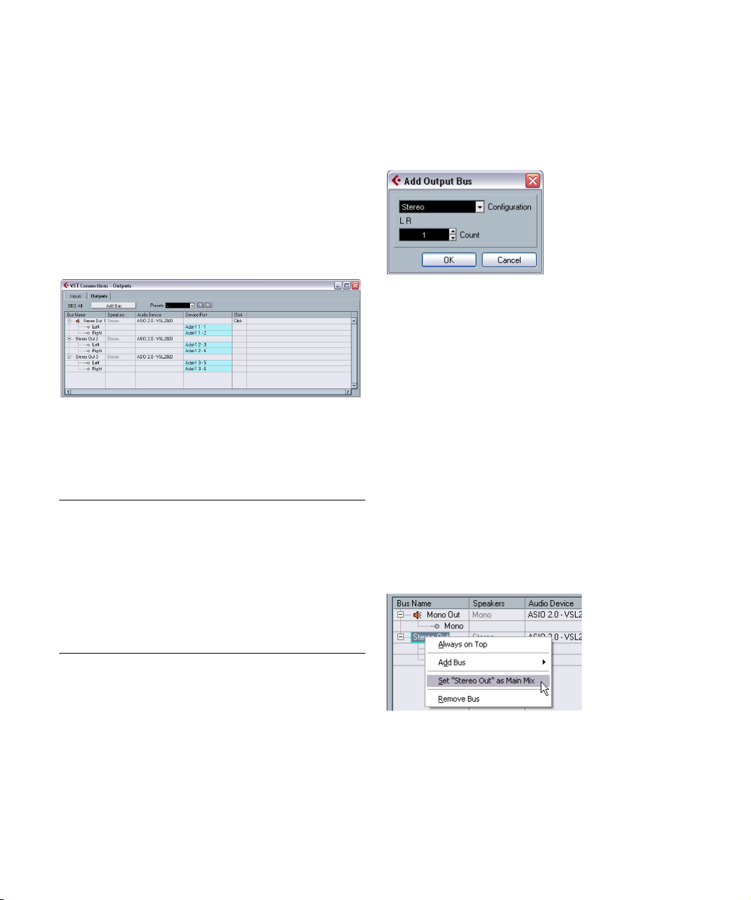
Adding a bus
1. Click the Inputs or Outputs tab depending on which
you want to add.
2. Click the Add Bus button.
A dialog appears.
3. Select the desired (channel) configuration.
You can add stereo and mono busses.
• Alternatively you can right-click in the VST Connections
window and add a bus in the desired format directly from
the context menu that appears.
The new bus appears with the ports visible.
4. Click in the Device Port column to select an input/out-
put port for a channel in the bus.
The pop-up menu that appears lists the ports with the names you have assigned in the Device Setup dialog. Repeat this for all channels in the bus.
Setting the Main Mix bus (the default output bus)
The Main Mix is the output bus that each new channel in
the mixer will be assigned to when it is created.
Any one of the output busses in the VST Connections
window can be the default output bus. By right-clicking on
the name of an output bus, you can set this bus as the
Main Mix bus.
Setting the default output bus in the VST Connections window.
11
VST Connections: Setting up input and output busses
Page 12
When creating new audio, group or FX channels in the
mixer, they will automatically be routed to the default bus.
!
The default bus is indicated by an orange colored
speaker icon next to its name in the VST Connections window.
Other bus operations
• To change the port assignment for a bus, you proceed
as when you added it – make sure the channels are visible
(by clicking the “+” button next to the bus, or by clicking
the “+ All” button at the top of the window) and click in the
Device Port column to select ports.
• To remove a bus you don’t need, select it in the list,
right-click and select “Remove Bus” from the pop-up
menu, or press [Backspace].
• You can store and recall bus presets with the pop-up
menu at the top of the window.
To store the current configuration as a preset, click the Store “+” button
and enter a name for the preset. You can then select the stored configuration directly from the Presets pop-up menu at any time. To remove a
stored preset, select it and click the “-” button.
Using the busses
This section describes briefly how to use the input and output busses you have created. For details refer to the chapters “Recording” on page 47 and “The mixer” on page 86.
For audio-related channel types other than audio track
channels (i.e. VST Instrument channels, ReWire channels,
Group channels and FX channels), only the Output Routing pop-up menu is available. Select one of its subtracks
in the Track list to open it.
When selecting an input bus for a track you can only select busses that correspond to the track’s channel configuration. Here are the details for input busses:
• Mono tracks can be routed to mono input busses or individual
channels within a stereo input bus.
• Stereo tracks can be routed to mono or stereo input busses.
For output busses any assignment is possible.
!
Assignments that will lead to feedback are not available in the pop-up menu. This is also indicated by a
one-way symbol.
To disconnect input or output busses, select “No Bus”
from the corresponding pop-up menu.
Viewing the busses in the mixer
Ö Note that only the output busses are available in the
mixer – not the input busses.
The available output busses are represented as output
channel strips in the mixer (shown in a separate pane to
the right). You can show or hide output channels by clicking the corresponding button in the mixer common panel:
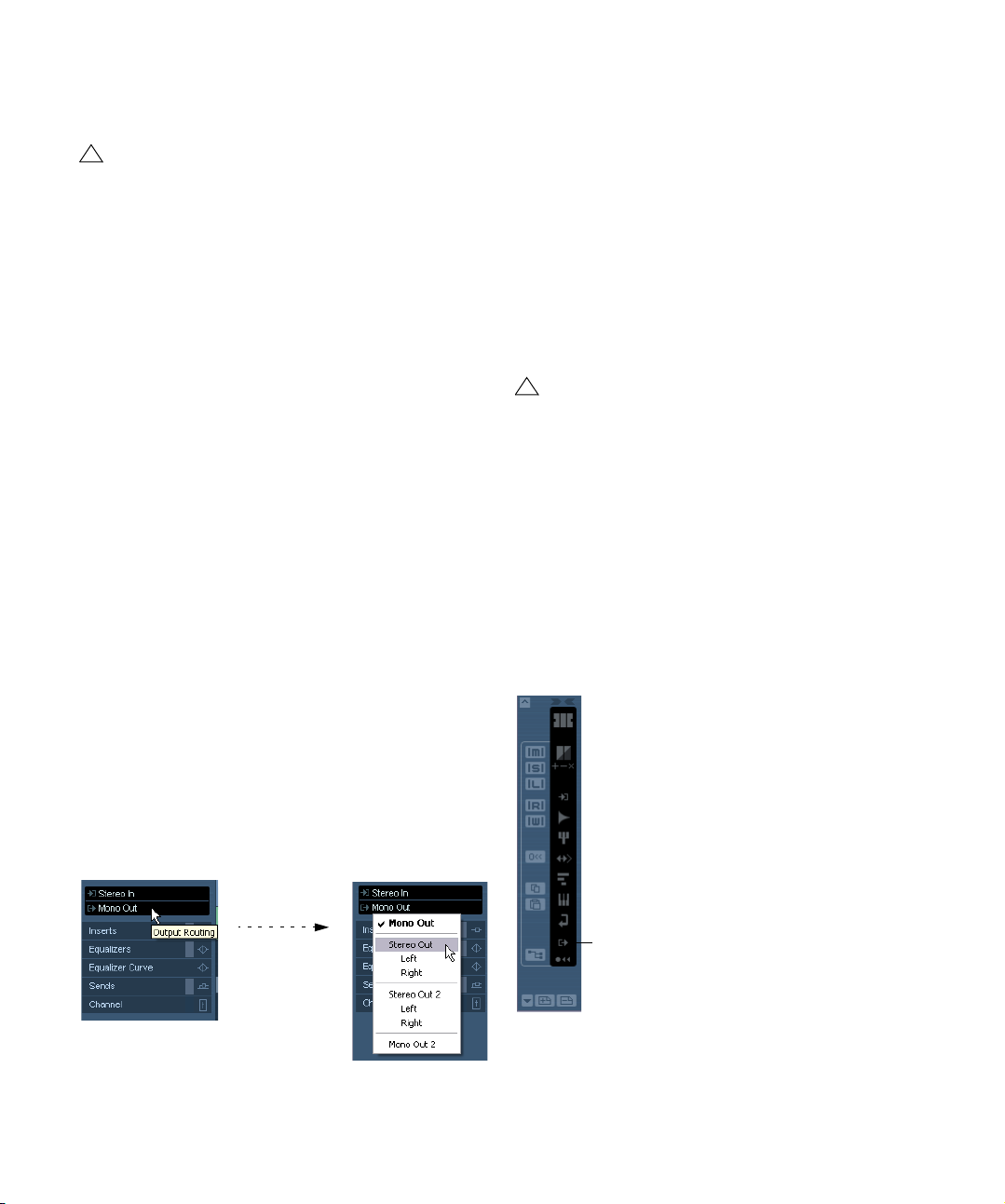
Routing
When you play back an audio track (or any other audio-related channel in the mixer, you route it to an output bus. In
the same way, when you record on an audio track you select from which input bus the audio should be sent.
• You can select input and output busses in the Inspector, using the Input and Output Routing pop-up menus.
VST Connections: Setting up input and output busses
Hide Output Channels
12
Page 13
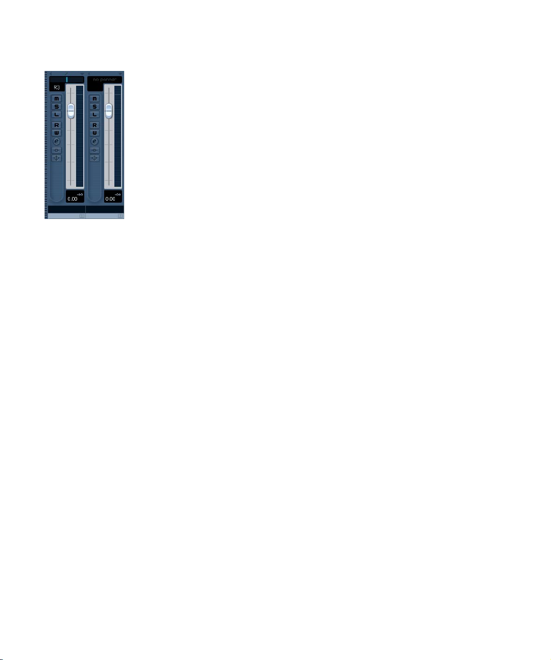
Output channels
The output channels are shown to the right in the mixer.
Here you can do the following:
• Adjust the output level for the busses with the faders.
• Open the Channel Settings window to add effects or EQ.
These will affect the whole bus. Examples of effects you may want to add
here include compressors, limiters and dithering. See the chapter “Audio
effects” on page 103.
About monitoring
The Main Mix bus (the default output bus) is used for monitoring (see “Setting the Main Mix bus (the default output
bus)” on page 11).
Setting the monitoring level
You can adjust the monitoring level in the Mixer.
When auditioning or scrubbing in the Sample Editor, you
can also set the monitoring level using the small fader on
the Sample editor toolbar.
VST Connections: Setting up input and output busses
13
Page 14

3
The Project window
Page 15
Background
The Project window is the main window in Cubase Essential. This provides you with an overview of the project, allowing you to navigate and perform large scale editing.
Each project has one Project window.
About tracks
The Project window is divided vertically into tracks, with a
timeline running horizontally from left to right. The following track types are available:
Track type Description
Audio For recording and playing back audio events and audio
Folder Folder tracks function as containers for other tracks,
FX Channel FX channel tracks are used for adding send effects. Each
Group Channel By routing several audio channels to a Group channel,
Instrument This allows you to create a track for a dedicated instru-
MIDI For recording and playing back MIDI parts. Each MIDI
parts. Each audio track has a corresponding audio channel in the mixer.
An audio track can have an automation subtrack for automating mixer channel parameters, effect settings, etc.
making it easier to organize and manage the track structure. They also allow you to edit several tracks at the
same time. See “Folder tracks” on page 77.
FX channel can contain up to eight effect processors – by
routing effect sends from an audio channel to an FX channel, you send audio from the audio channel to the effect(s)
on the FX channel. Each FX channel has a corresponding
channel strip in the mixer – in essence an effect return
channel. See the chapter “Audio effects” on page 103.
An FX channel can also have an automation subtrack for
automating mixer channel parameters, effect settings etc.
All FX channel tracks are automatically placed in a special
FX channel folder in the Track list, for easy management.
you can submix them, apply the same effects to them,
etc. (see “Using group channels” on page 98).
A Group channel track contains no events as such, but
displays settings and automation curves for the corresponding Group channel. Each Group channel track has
a corresponding channel strip in the mixer. In the Project
window, Group channels are organized as tracks in a
special Group Tracks folder.
ment, making e.g. VST instrument handling easier and
more intuitive. Instrument tracks have a corresponding
channel strip in the mixer. Each instrument track can have
an automation subtrack in the Project window. However,
Volume and Pan are automated from within the mixer. For
more information on instrument tracks, see “VST Instru-
ments and Instrument tracks” on page 119.
track has a corresponding MIDI channel strip in the mixer.
A MIDI track can have an automation subtrack for automating mixer channel parameters, insert and send effect
settings etc.
Track type Description
Marker The Marker track displays markers which can be moved
Arranger The Arranger track is used for arranging your project, by
Video For playing back video events. A project can only have
and renamed directly in the Project window (see “Using
the Marker track” on page 83). A project can have only
one marker track.
marking out sections in the project and determining in
which order they should be played back. See “The Arran-
ger track” on page 70.
one video track.
About parts and events
Events are the basic building blocks in Cubase Essential.
Different event types are handled differently in the Project
window:
• Video events and automation events (curve points) are always
viewed and rearranged directly in the Project window.
• MIDI events are always gathered in MIDI parts, containers for
one or more MIDI events. MIDI parts are rearranged and manipulated in the Project window. To edit the individual MIDI
events in a part, you have to open the part in a MIDI editor (see
“The MIDI editors” on page 224).
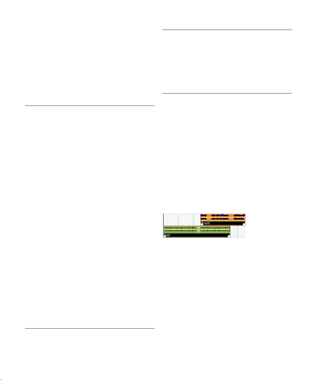
• Audio events can be displayed and edited directly in the Project
window, but you can also work with audio parts containing several events. This is useful if you have a number of events which
you want to treat as one unit in the project. Audio parts also
contain information about the time position in the project.
An audio event and an audio part
15
The Project window
Page 16

Audio handling
When you work with audio files, it is crucial to understand
how audio is handled in Cubase Essential:
When you edit or process audio in the project window,
you always work with an audio clip that is automatically
created on import or during recording. This audio clip refers to an audio file on the hard disk that itself remains untouched. This means, that audio editing and processing is
“non-destructive”, in the sense that you can always undo
changes or revert to the original versions.
An audio clip does not necessarily refer to just one original audio file! If you apply e.g. some processing to a specific section of an audio clip, this will create a new audio
file containing only this section. The processing will then
be applied to the new audio file only, leaving the original
audio file unchanged. Finally, the audio clip is automatically adjusted, so that it refers both to the original file and
to the new, processed file. During playback, the program
will switch between the original file and the processed file
at the correct positions. You will hear this as a single recording, with processing applied to one section only. This
feature makes it possible to undo processing at a later
stage, and to apply different processing to different audio
clips that refer to the same original file.
An audio event is the object that you place on a time position in Cubase Essential. If you make copies of an audio
event and move them to different positions in the project,
they will still all refer to the same audio clip. Furthermore,
each audio event has an Offset value and a Length value.
These determine at which positions in the clip the event
will start and end, i.e. which section of the audio clip will
be played back by the audio event. For example, if you resize the audio event, you will just change its start and/or
end position in the audio clip – the clip itself will not be affected.
Ö If you want to use one audio file in different contexts, or
if you want to create several loops from one audio file, you
should convert the corresponding regions of the audio clip
to events and bounce them into separate audio files. This is
necessary since different events that refer to the same clip
access the same clip information.
The Project window
16
Page 17
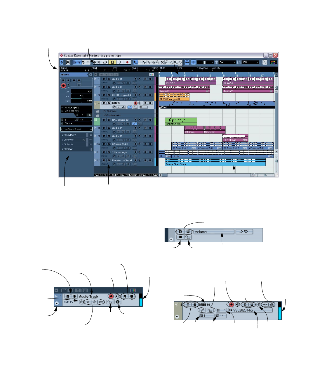
Window Overview
The rulerThe info line The toolbar
The Inspector
The Track list with
various track types
The Track list
The Track list displays all the tracks used in a project. It
contains name fields and settings for the tracks. Different
track types have different controls in the Track list. To see
all the controls you may have to resize the track in the Track
list (see “Resizing tracks in the Track list” on page 23).
• The Track list area for an audio track:
Mute &
Solo
Edit channel
settings
Show/hide
automation
Indicates whether effect sends, EQ or insert effects are activated for
the track. Click to bypass.
Automation Read/Write buttons
Track name
Record Enable &
Monitor buttons
Lock track
button
Track activity
indicator
Freeze Audio
Channel
The Project window
The event display, showing audio parts and
events, MIDI parts, automation, markers, etc.
• The Track list area for an automation subtrack (opened
by clicking the Show/Hide Automation button on a track):
Automation Read/Write buttons
Mute Lock track
button
Automation parameter
(click to select parameter)
• The Track list area for a MIDI track:
Track name
Mute & Solo
17
Record Enable &
Monitor buttons
Drum map and Lock
track buttons
Bank
Patch
Effect sends and insert effects
indicators and bypass
Read/Write
buttons
MIDI channel
MIDI Output
Edit channel
settings
Track
activity
indicator
Page 18
The Inspector
The area to the left of the Track list is called the Inspector.
This shows additional controls and parameters for the track
you have selected in the Track list. If several tracks are selected (see “Handling tracks” on page 26), the Inspector
shows the setting for the first (topmost) selected track.
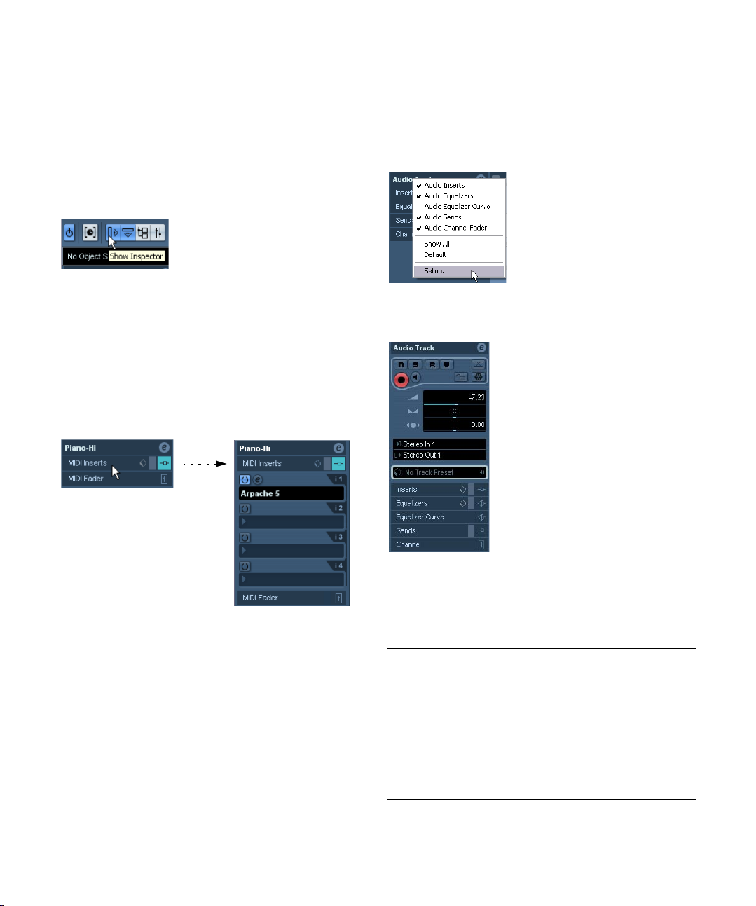
To hide or show the Inspector, click the Inspector icon in
the toolbar.
The Inspector icon
• For most track classes, the Inspector is divided into a
number of sections, each containing different controls for
the track. You can hide or show sections by clicking on
their respective names.
Clicking the name for a hidden section brings it into view and hides the
other sections. [Ctrl]/[Command]-clicking the section name allows you
to hide or show a section without affecting the other sections. Finally,
[Alt]/[Option]-clicking a section name shows or hides all sections in the
Inspector.
Ö Please note that not all Inspector tabs are shown by
default. You can show/hide Inspector sections by rightclicking on an Inspector tab and activating/deactivating
the desired option(s).
Make sure you right-click on an inspector tab and not on the empty area
below the Inspector, as this will open the Quick context menu instead.
The Inspector Setup context menu
Sections
• You can also use key commands to show different Inspector sections.
These are set up in the Key Commands dialog, see “Setting up key com-
mands” on page 322.
Ö Hiding a section does not affect its functionality.
In other words, if you have set up a track parameter or activated an effect
for example, your settings will still be active even if you hide the respective Inspector section.
Which sections are available in the Inspector depends on
the selected track.
The Project window
The Inspector contains the controls that can be found on
the Track list, plus some additional buttons and parameters. In the table below, these additional settings and the
available sections are listed. Which sections are available
for which track type is described in the following sections.
Parameter Description
Auto Fades
Settings button
Edit Channel
settings
Volume Use this to adjust the level for the track. Changing this
18
Opens a dialog in which you can make separate Auto
Fade settings for the track. See “Making Auto Fade set-
tings for a separate track” on page 69.
Opens the Channel Settings window for the track, allowing you to view and adjust effect and EQ settings, etc.
See “Using Channel Settings” on page 94.
setting will move the track’s fader in the mixer window,
and vice versa. See “Setting volume in the mixer” on page
92 to learn more about setting levels.
Page 19
Parameter Description
Pan Use this to adjust the panning of the track. As with the
Delay This adjusts the playback timing of the audio track. Posi-
Input Routing This lets you specify which Input bus or MIDI input the
Output Routing Here you decide to which output the track should be
Inserts section Allows you to add insert effects to the track, see the
Equalizers
section
Equalizer Curve
section
Sends section Allows you to route an audio track to one or several FX
Channel section Shows a duplicate of the corresponding mixer channel
Volume setting, this corresponds to the Pan setting in the
mixer.
tive values delay the playback while negative values
cause the track to play earlier. The values are set in milliseconds.
track should use (see “Setting up busses” on page 10 for
information about Input busses).
routed. For audio tracks you select an output bus (see
“Setting up busses” on page 10) or Group channel, for
MIDI tracks you select a MIDI output.
chapter “Audio effects” on page 103. The Edit button at
the top of the section opens the control panels for the
added insert effects.
Lets you adjust the EQs for the track. You can have up to
four bands of EQ for each track, see “Making EQ set-
tings” on page 96. The Edit button at the top of the sec-
tion opens the Channel Settings window for the track.
Lets you adjust the EQs for the track graphically, by clicking and dragging points in a curve display.
channels (up to eight), see the chapter “Audio effects” on
page 103. For MIDI tracks, this is where you assign MIDI
send effects. The Edit button at the top of the section
opens the control panel for the first effect in each FX
channel.
strip. The channel overview strip to the left lets you activate and deactivate insert effects, EQs and sends.
Audio tracks
For audio tracks, all settings and sections listed above are
available.
MIDI tracks
When a MIDI track is selected, the Inspector contains a
number of additional sections and parameters, affecting the
MIDI events in real time (e.g. on playback). Which sections
are available for MIDI tracks is described in the chapter
“MIDI realtime parameters and effects” on page 205.
Marker tracks
When the marker track is selected, the Inspector shows
the marker list. See “The Marker window” on page 82.
Video tracks
When a video track is selected, the Inspector contains a
lock button for locking the track (see “Locking events” on
page 34) and a Mute button for interrupting video play-
back.
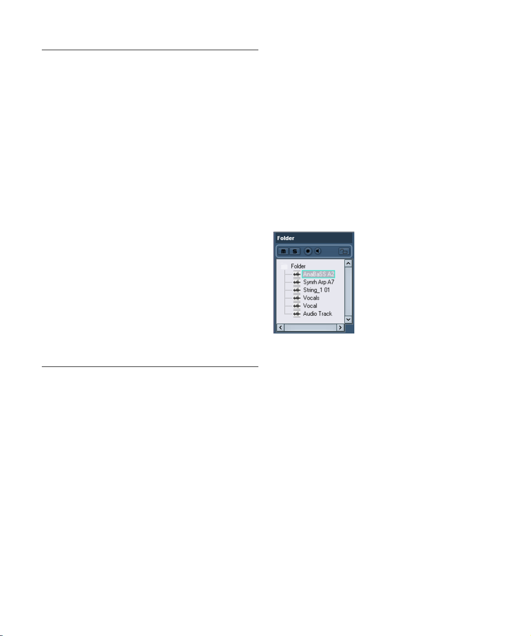
Folder tracks
When a folder track is selected, the Inspector shows the
folder and its underlying tracks, much like a folder structure in the Windows Explorer or Mac OS X Finder.
Ö You can click one of the tracks shown under the folder
in the Inspector to have the Inspector show the settings
for that track.
This way, you don’t have to “open” a folder track to make settings for
tracks within it.
Here, an audio track within the folder is selected.
FX channel tracks
When an FX channel track is selected, the following controls and sections are available:
• Edit button.
• Volume control.
•Pan control.
• Output routing pop-up menu.
• Inserts section.
• Equalizers section.
• Equalizer Curve section.
• Sends section.
• Channel section.
19
The Project window
Page 20
FX channel folder tracks
FX channel tracks are automatically placed in a special
folder, for easier management. When this folder track is
selected, the Inspector shows the folder and the FX channels it contains. You can click one of the FX channels
shown in the folder to have the Inspector show the settings for that FX channel – this way you don’t have to
“open” a folder track to access the settings for the FX
channels in it.
Group channel tracks
When a Group channel track is selected, the following
controls and sections are available:
• Edit button.
• Volume control.
• Pan control.
• Output routing pop-up menu.
• Inserts section.
• Equalizers section.
• Equalizer Curve section.
• Sends section.
• Channel section.
Group channel folder tracks
Just like FX channel tracks, all Group channel tracks are
placed in a separate folder – when this is selected, the Inspector shows the folder and the Group channels it contains. You can click one of the Group channels shown in
the folder to have the Inspector show the settings for that
Group channel – this way, you don’t have to “open” a folder
track to access the settings for the Group channels in it.
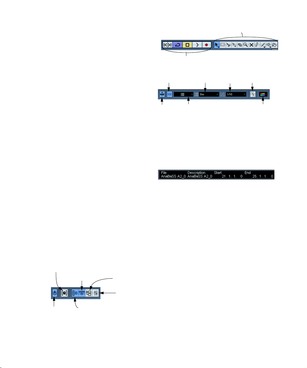
The toolbar
The toolbar contains tools and shortcuts for opening other
windows and various project settings and functions:
Constrain delay compensation (see “Constrain Delay
Compensation” on page 129).
Show/hide info line
Open Pool
Open Mixer
Project window tools
Transport controls
(Previous/Next Marker, Cycle, Stop, Play, and Record)
Snap
on/off
Autoscroll
Autoscroll
on/off
on/off
Grid popup menu
Snap mode
Quantize
value
Snap to Zero
Crossings
Color popup menu
Ö In addition to these, the toolbar can contain a number
of other tools and shortcuts, not visible by default. How to
set up the toolbar and specify which tools should be displayed or hidden is described in the section “The Setup
dialogs” on page 314.
The info line
The info line shows information about the currently selected event or part in the Project window. You can edit almost all values on the info line using regular value editing.
Length and position values are displayed in the format currently selected for the ruler (see “The ruler” on page 21).
• To hide or show the info line, click the Show Event Info-
line button on the toolbar.
The following elements can be selected for display and
editing on the info line:
• Audio events.
•Audio parts.
• MIDI parts.
• Video events.
•Markers.
• Automation curve points.
• Arranger events.
Active project indicator Show/hide Inspector
20
The Project window
Page 21

When several elements are selected
• If you have several elements selected, the info line will
show information about the first item in the selection. The
values will be shown in yellow to indicate that several elements are selected.
• If you edit a value on the info line, the value change is
applied to all selected elements, relatively to the current
values.
If you have two audio events selected and the first is one bar long and
the other two bars long, the info line shows the length of the first event
(one bar). If you now edit this value to 3 bars in the info line, the other
event will be resized by the same amount – and will thus be 4 bars long.
• If you press [Ctrl]/[Command] and edit on the info line,
the values will be absolute instead. In our example above,
both events would be resized to 3 bars. Note that [Ctrl]/
[Command] is the default modifier key for this – you can
change this in the Preferences (Editing–Tool Modifiers
page, under the Info Line category).
Editing Transpose and Velocity for MIDI parts
When one or several MIDI parts are selected, the info line
contains Transpose and Velocity fields.
• Adjusting the Transpose field transposes the selected
parts in semitone steps.
Note that this transposition doesn’t change the actual notes in the part –
it’s just a “play parameter”, affecting the notes on playback. The transposition you specify for a part on the info line is added to the transposition
set for the whole track.
• Adjusting the Velocity field shifts the velocity for the selected parts – the value you specify is added to the velocities of the notes in the parts.
Again, this velocity shift only affects the notes on playback, and again,
the value you specify is added to the Vel.Shift. value set for the whole
MIDI track in the Inspector.
Getting on-the-fly info with the Arrow tool
If the option “Select Tool: Show Extra Info” is activated in
the Preferences (Editing–Tools page), a tool tip will be
shown for the Arrow tool, displaying information depending
on where you point it. For example, in the Project window
event display, the tool will show the current pointer position
and the name of the track and event you’re pointing at.
The ruler
The ruler at the top of the event display shows the timeline. Initially, the Project window ruler uses the display format specified in the Project Setup dialog (see “The
Project Setup dialog” on page 22), as do all other rulers
and position displays in the project. However, you can select an independent display format for the ruler by clicking
the arrow button to the right of it and selecting an option
from the pop-up menu that appears (you can also bring up
this pop-up menu by right-clicking anywhere in the ruler).
Option Positions and lengths displayed as
Bars+Beats Bars, beats, sixteenth notes and ticks. By default there
Seconds Hours, minutes, seconds and milliseconds.
Timecode This format displays hours, minutes, seconds and frames.
Samples Samples.
Time Linear When this is selected, the ruler will be linear relative to
Bars+Beats
Linear
• The selection you make here affects the ruler, the info
line and tool tip position values (which appear when you
drag an event in the Project window).
You can also select independent formats for other rulers and position
displays.
• To set the display format globally (for all windows), use
the primary display format pop-up on the Transport panel,
or hold down [Ctrl]/[Command] and select a display format in any ruler.
• If you use the “Timecode” option and the option “Show
Timecode Subframes” is activated in the Preferences
(Transport page), the frames will also display subframes.
There are 80 subframes per frame.
are 120 ticks per sixteenth note.
The number of frames per second (fps) is set in the
Project Setup dialog (see “The Project Setup dialog” on
page 22). You can choose between 24, 25, 29.97 and
30 fps or 29.97 and 30 dfps (“drop frame”).
time. This means that if there are tempo changes on the
Tempo track, the distance between the bars will vary in
Bars+Beats mode.
When this is selected, the ruler will be linear relative to
the meter position – bars and beats. This means that if
there are tempo changes on the Tempo track, there still
will be the same distance between bars in Bars+Beats
mode. If the ruler is set to a time-based mode, the distance between seconds will vary depending on the
tempo changes.
21
The Project window
Page 22
Operations
Creating a new project
You create a new project in the following way:
1. Select “New Project” from the File menu.
A dialog appears, listing a number of project templates, including any
custom templates you may have created (see “Save as Template” on
page 305).
2. Select a template and click OK.
A file dialog appears, allowing you to specify a location for the project
folder. This will contain all files related to the project.
3. Select an existing folder or type the name of a new
one. Click OK.
A Project window appears. The new project will be based on the selected
template, and include tracks, events and settings from the template.
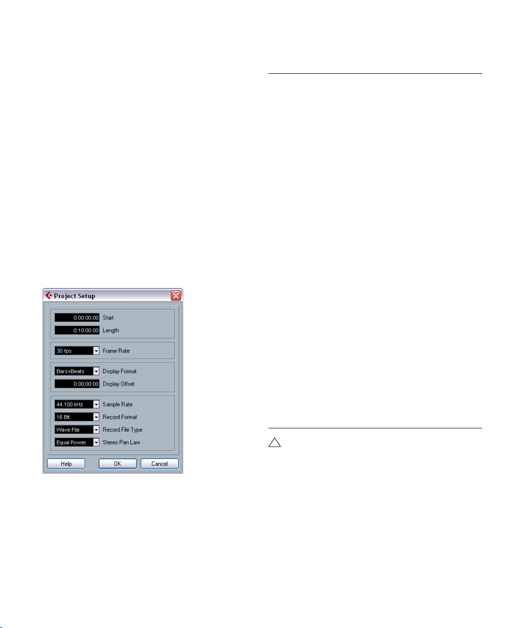
The Project Setup dialog
General settings for the project are made in the Project
Setup dialog. This is opened by selecting “Project
Setup…” from the Project menu.
The following settings are available in the Project Setup
dialog:
Setting Description
Start The start time of the project. Allows you to have the
Length The length of the project.
Frame Rate Used when synchronizing Cubase Essential with external
Display Format This is the global display format used for all rulers and
Display Offset Offsets the time positions displayed in the ruler etc., al-
Sample Rate The sample rate at which Cubase Essential records and
Record Format/
File Type
Stereo Pan Law Decides whether panning should use power compensa-
project start at another time than zero. Also used for setting the sync start position when synchronizing Cubase
Essential to external devices (see “Setting up Cubase
Essential for external sync to timecode” on page 283).
When you change this setting you will be asked whether
you want to keep the project content at its timecode positions. “Yes” means that all events will stay at their original timecode positions – i.e. they will be moved in relation
to the start of the project. “No” means that all events keep
their position relative to the project start.
equipment. If Cubase Essential is slave, this value is automatically set to the frame rate of the incoming sync signal. If Cubase Essential is the master, this determines the
frame rate of the sent sync signal. See “Setting the Frame
Rate” on page 281.
position displays in the program. However, you can make
independent display format selections for the individual
rulers and displays if you like.
For descriptions of the different display format options,
see “The ruler” on page 21.
lowing you to compensate for the Start position setting.
Typically, if you synchronize Cubase Essential to an external source starting at a frame other than zero, you set
the Start position to this value. However, if you still want
the display in Cubase Essential to start at zero, set the
Display Offset to the same value too.
plays audio.
When you record audio in Cubase Essential, the files that
are created will be of this resolution and file type. See
“Selecting a recording file format” on page 50.
tion or not (see “About the “Stereo Pan Law” Preference
(audio channels only)” on page 94).
!
22
The Project window
While most Project Setup settings can be changed at
any time, you should select a sample rate once and for
all when starting with a new project! All audio files
must be of this sample rate to play back correctly.
Page 23
Zoom and view options
Zooming in the Project window is done according to the
standard zoom techniques, with the following special
notes:
• When you are using the Zoom tool (magnifying glass),
the result depends on the option “Zoom Tool Standard
Mode: Horizontal Zooming Only” in the Preferences (Editing–Tools page).
If this is activated and you drag a selection rectangle with the Zoom tool,
the window will only be zoomed horizontally (track height will not change).
If the option is off, the window will be zoomed both horizontally and vertically.
• When using the vertical zoom sliders, the tracks are
scaled relatively.
In other words, if you have made any individual track height adjustments
(see below), the relative height differences are maintained.
You find the following options are available on the Zoom
submenu on the Edit menu:
Option Description
Zoom In Zooms in one step, centering on the project cursor.
Zoom Out Zooms out one step, centering on the project cursor.
Zoom Full Zooms out so that the whole project is visible. “The whole
Zoom to
Selection
Zoom to
Selection
(Horiz)
Zoom to Event This option is available only in the Sample Editor (see
Zoom In
Vertical
Zoom Out
Vertical
Zoom In
Tracks
Zoom Out
Tracks
Zoom Selected
Tracks
• If the option “Zoom while Locating in Time Scale” is activated in the Preferences (Transport page), you can also
zoom by clicking in the main ruler and dragging up or
down with the mouse button pressed.
Drag up to zoom out; drag down to zoom in.
project” means the timeline from the project start to the
length set in the Project Setup dialog (see above).
Zooms in horizontally and vertically so that the current selection fills the screen.
Zooms in horizontally so that the current selection fills the
screen.
“Zooming” on page 154).
Zooms in one step vertically.
Zooms out one step vertically.
Zooms in on the selected track(s) one step vertically.
Zooms out the selected track(s) one step vertically.
This zooms in vertically on the selected track(s) and minimizes the height of all other tracks.
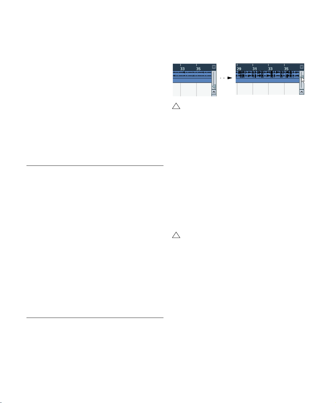
• You can zoom the contents of parts and events verti-
cally, using the waveform zoom slider in the top right corner of the event display.
This is useful when viewing quiet audio passages.
!
To get an approximate reading on the level of the audio events by viewing the waveforms, make sure this
slider is all the way down. Otherwise, zoomed waveforms may be mistaken for clipped audio.
• If you activate the option Quick Zoom in the Prefer-
ences (Editing page), the contents of parts and events will
not be continuously redrawn when you zoom manually.
Instead, the contents are redrawn once you have stopped changing the
zoom – activate this if screen redraws are slow on your system.
Resizing tracks in the Track list
• You can change the height of an individual track by
clicking on its lower border in the Track list and dragging
up or down.
To change the height of all tracks simultaneously, hold down [Ctrl]/
[Command] and resize one of the tracks in this way. If “Snap Track
Heights” is activated on the Track scale pop-up (see below), the track
height will change in fixed increments when you resize it.
!
This behavior is different when “Enlarge Selected
Track” is activated on the Edit menu (see below).
• You can also change the width of the Track list area, by
dragging the border between the Track list and the event
display.
• By default, the controls shown for tracks in the Track list
will adapt to the track size. This means that when resizing
a track’s height or width the controls will be placed where
they best “fit in”.
If you prefer to have the controls in fixed positions, you can deactivate the
option “Wrap Controls” in the Track Controls settings dialog (see “Cus-
tomizing track controls” on page 315).
• You can decide for each track type what controls
should be shown in the Track list – see “Customizing
track controls” on page 315.
23
The Project window
Page 24
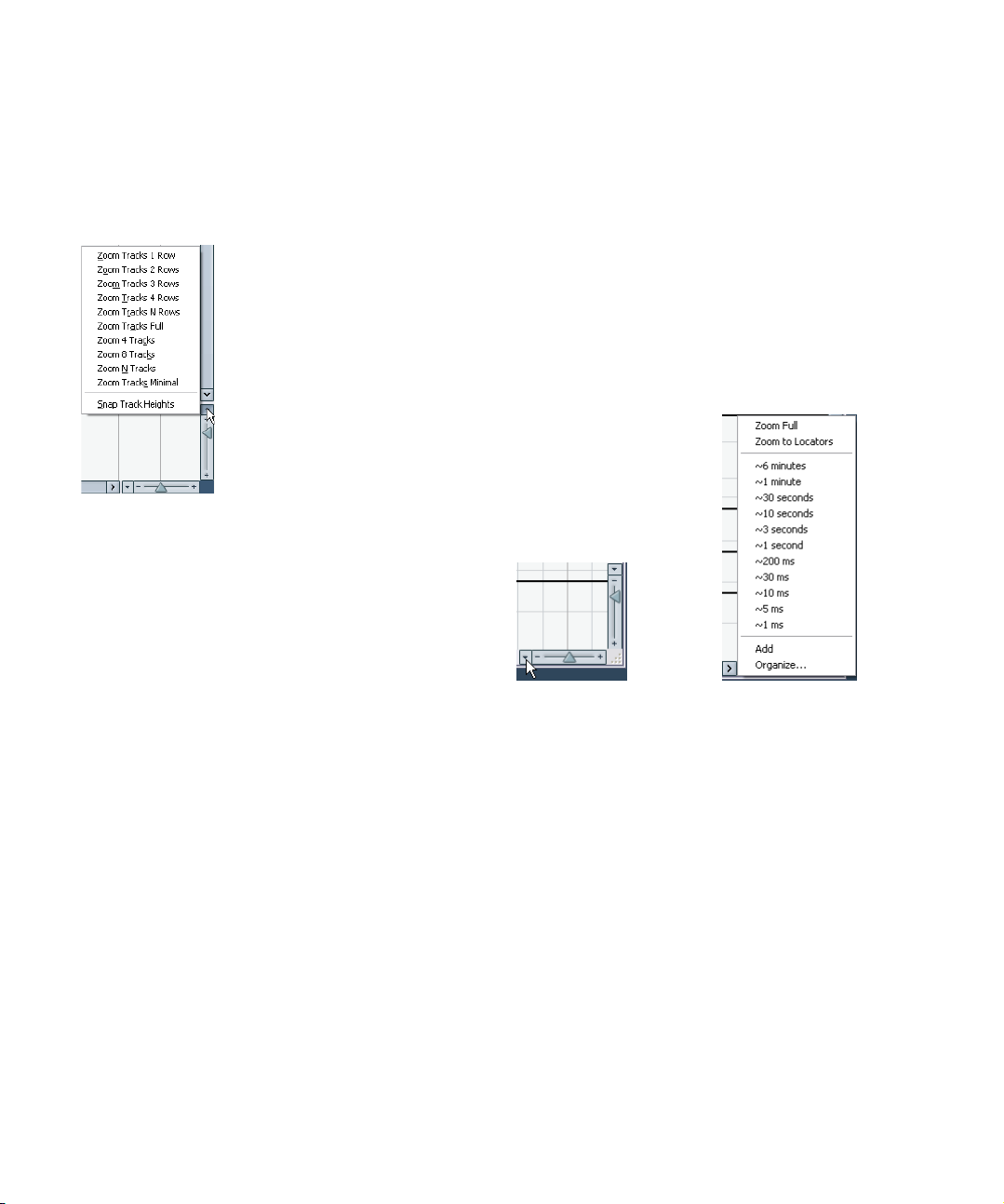
• You can use the Track scale pop-up (opened by clicking
the arrow button above the vertical zoom control) to set the
number of tracks to view in the current Project window.
The track height will be adjusted to show only the number of tracks specified on the pop-up menu. By selecting “Zoom N Tracks” from the popup you can manually set the number of tracks to fit in the current Project
window.
The Enlarge Selected Track option
When this option is activated on the Edit menu (or in the
Preferences, Editing–Project & Mixer page), the selected
track is enlarged automatically. This is useful if you are
stepping through the tracks in the track list, to check or
edit the settings. The tracks will revert to the size they had
before when they are deselected. You can adjust the size
directly in the Track list if the default enlargement factor
does not suit you.
While this is the program behavior you will want in most
cases, it may be a disadvantage when changing the track
height you started out with for one or more tracks (i.e. their
“original” height, before “Enlarge Selected Track” was activated). As soon as you try to resize a track, it is selected
and automatically enlarged. Instead of turning off “Enlarge
Selected Track”, resizing the desired track(s) and the activating “Enlarge Selected Track” again, you can resize a
track in the Track list without selecting it.
Proceed as follows:
1. Move the mouse pointer over the lower border of the
(unselected) track you want to resize.
The mouse pointer turns into a divider symbol.
2. Hold down [Alt]/[Option] and drag the lower border of
the track until it reaches the desired height.
Now, when you select this track, (and “Enlarge Selected Track” is activated), it will be enlarged. It will revert to the changed size, when you select a different track.
Zoom presets and Cycle markers
The pop-up menu to the left of the horizontal zoom control
allows you to select, create and organize zoom presets.
These are useful if you want to toggle between different
zoom settings (e.g. one where the whole project is displayed in the project window and another with a high
zoom factor for detailed editing). With this pop-up menu,
you can also zoom in on the area between cycle markers
in the project.
Click here…
…to open the context menu.
The upper part of the menu lists the zoom presets:
• To store the current zoom setting as a preset, select
Add from the pop-up menu.
A dialog appears, allowing you to type in a name for the preset.
• To select and apply a preset, select it from the pop-up
menu.
• The “Zoom Full” preset is always available. Selecting
this option zooms out so that the whole project is visible.
“The whole project” means the timeline from the project
start to the length set in the Project Setup dialog (see
“The Project Setup dialog” on page 22).
• If you want to delete a preset, select “Organize…” from
the pop-up menu.
In the dialog that appears, select the preset in the list and click the Delete button. The preset is removed from the list.
24
The Project window
Page 25
• If you want to rename a preset, select “Organize…”
from the pop-up menu.
In the dialog that appears, select the desired preset in the list and click
the Rename button. A second dialog opens, allowing you to type in a
new name for the preset. Click OK to close the dialogs.
!
Zoom presets are global for all projects, i.e. they are
available in all projects you open or create.
The middle part of the pop-up lists any cycle markers you
have added in the project:
• If you select a cycle marker from this menu, the event
display is zoomed in to encompass the marker area (see
“Zooming to cycle markers” on page 84).
• You cannot edit the cycle markers in this pop-up menu.
For information on editing markers, see “The Marker win-
dow” on page 82.
!
Only the cycle markers you create in the current
project are available on the menu.
Adjusting how parts and events are shown
The Preferences on the File menu (the Cubase Essential
menu, under Mac OS X) contains several settings for customizing the display in the Project window.
The Event Display page contains common settings for all
track types:
Option Description
Colorize Event
Background
Show Event
Names
Transparent
Events
Show Data on
Small Track
Heights
Determines whether the backgrounds or “contents” (waveforms, etc.) of parts and events will be colorized. See
“Handling tracks” on page 26.
Determines whether the names of parts and events should
be shown in the Project window.
When this is activated, events and parts will be transparent,
showing the waveforms and MIDI events only.
If this is activated, the contents of events and parts will be
shown, even if the height of a track is very small.
The Event Display–Audio page contains settings for audio
events:
Option Description
Interpolate
Audio Images
Wave Image
Style
Show Event
Volume Curves
Always
Fade Handles
always on top
Thick Fade
Lines
Show
Waveforms
Background
Color
Modulation
If the option is deactivated, single sample values are
drawn as “steps”. If the option is activated they are interpolated to form “curves”.
Determines whether audio waveforms should be displayed as solid images, frames or “inverted” images
(solid+frame). This selection affects all waveform images
in the Project window, Sample Editor and Audio Part Editor.
Note that the “Framed” and “Solid and Framed” styles
are more demanding for the computer. If the system feels
slower in these modes, please switch back to “Solid”
wave image style.
If this is activated the “volume curves” created with the
volume and fade handles are always shown – if not, the
curves are only shown for selected events.
When this option is activated, the fade handles stay at
the top of the event, and vertical help lines indicate the
exact end or start points of fades.
If this option is activated, the fade lines and volume
curves are thicker, increasing their visibility.
Determines whether audio waveforms should be shown
at all.
When this is activated, the backgrounds of audio waveforms are displayed in a different way, reflecting the waveform dynamics. This is especially useful to get an overview
when working with small track heights.
The Event Display–MIDI page contains settings for MIDI
parts:
Option Description
Default Edit
Action
Part Data
Mode
Show
Controllers
Edit as Drums
when Drum Map
is assigned
Note Name
Style
Determines which editor should be opened when you
double-click a MIDI part or select it and press [Ctrl]/
[Command]-[E]: the Key, List, Drum or Score editor. Note
that this setting is overridden for tracks with drum maps if
the option “Edit as Drums when Drum Map is assigned”
(see below) is activated
Determines if and how events in MIDI parts should be
shown in the Project window: as score notes, as drum
notes or as lines. If “No Data” is selected, events will not
be shown at all. Note that this setting is overridden for
tracks with drum maps if the option “Edit as Drums when
Drum Map is assigned” (see below) is activated.
Governs whether non-note events (controllers, etc.)
should be shown in MIDI parts in the Project window.
If this is activated, parts on MIDI tracks with drum maps
assigned will be shown with drum note symbols in the
Project window. Also, the parts will automatically open in
the Drum editor when double-clicked (overriding the Default Edit Action setting above).
Determines how MIDI note names (pitches) should be
displayed in editors, etc.
25
The Project window
Page 26
The Event Display–Video page contains settings for video
events:
Option Description
Show Video
Thumbnails
Video Cache
Size
When this is activated, thumbnail frames of the video
contents are shown on the Video track.
This determines how much memory is available for video
thumbnails. If you have long video clips and/or work with
a large zoom factor (so that a lot of frames are shown in
the thumbnails), you may have to raise this value.
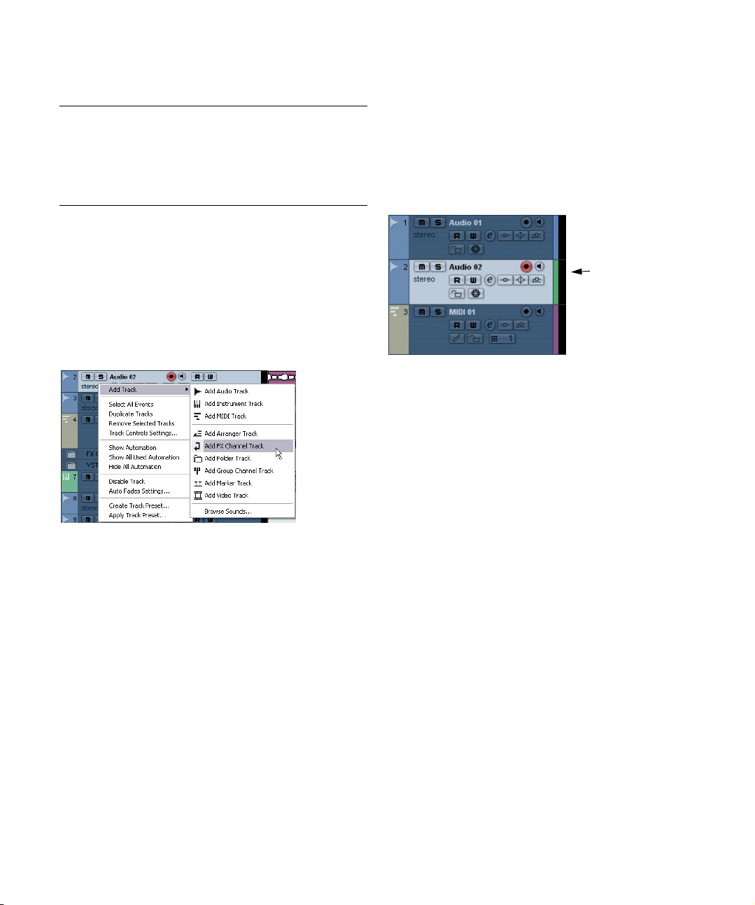
Handling tracks
To add a track to the project, select “Add Track” from the
Project menu and select a track type from the submenu
that appears. The new track is added below the currently
selected track in the Track list.
• The items on the “Add Track” submenu are also available on the Quick menu.
This is accessed by right-clicking in the Track list.
• If you select Audio, MIDI, Group Channel or Instrument
from the Add Track submenu, a dialog opens, allowing
you to insert several tracks in one go.
Just enter the desired number of tracks in the value field.
• For audio and group channel tracks, the channel configuration – mono or stereo – can be set in the Configuration
pop-up.
• The Browse Sounds option in the Add Track dialog is
described in the chapter “Track Presets” on page 195.
• In the Preferences (Editing–Project & Mixer page, you
can find the option “Auto Track Color Mode”.
This offers you several options for automatically assigning colors to
tracks that are added to the project.
Once you have created tracks, you can manipulate and rearrange them in various ways:
• To rename a track, double-click in the name field and
type in a new name.
If you hold down any modifier key when pressing [Return] to close the
name field, all events on the track will get the name you entered.
• To select a track, click on it in the Track list.
A selected track is indicated by a light gray color in the Track list.
This track is selected.
It is possible to select several tracks by pressing [Ctrl]/[Command] and
clicking on them. [Shift]-click to select a continuous range of tracks.
• To move a track, click and drag it up or down in the list.
• To duplicate a track, complete with all contents and
channel settings, right-click in the Track list and select
“Duplicate tracks” from the context menu, or select “Duplicate tracks” from the Project menu.
The duplicated track will appear below the original track.
• You can select a default color for a track by activating
“Show Track Colors” above the Track list and selecting a
color from the Color pop-up menu on the toolbar. This
color will be used for all events on the track and will also
be shown in the Mixer. You can override the default track
color for individual events and parts by using the Color
tool or the Color Selector pop-up menu.
The option “Colorize Event Background” in the Preferences dialog (Event
Display page) determines whether the backgrounds or waveforms of
events will be colorized.
• To remove a track, right-click on it in the Track list and
select “Remove Selected Tracks” from the context menu.
You can also remove multiple selected tracks, by selecting “Remove Selected Tracks” either from the Project menu or from the context menu.
• To change the track height of an individual track, click
on its lower border in the Track list and drag up or down,
see “Resizing tracks in the Track list” on page 23.
26
The Project window
Page 27
Ö Note that you can also automatically enlarge the selected track, see “The Enlarge Selected Track option” on
page 24.
Disabling audio tracks
Audio tracks can be disabled by selecting “Disable Track”
from the Track list context menu. Disabling a track is similar to muting it (see “Muting events” on page 34), since a
disabled track will not be played back. However, disabling
a track not only “zeroes” the output volume from the track,
but actually shuts down all disk activity for it. See “About
track disable/enable” on page 45 for more information.
Adding events to a track
There are a number of ways to add events to a track:
• By recording (see “Basic recording methods” on page
48).
This is possible for audio and MIDI tracks.
• By selecting “Audio File…” or “Video File…” from the
Import submenu on the File menu.
This opens a file dialog, allowing you to locate the file you wish to import.
When you import a file this way, a clip is created for the file and an event
that plays the whole clip is inserted on the selected track, at the position
of the project cursor.
You can also import MIDI files by using the Import submenu, but this
works in a slightly different way (see “Exporting and importing standard
MIDI files” on page 310).
• By grabbing audio CD tracks and converting them to audio files (see “Importing audio CD tracks” on page 307).
• By using Copy and Paste on the Edit menu.
This allows you to copy all kinds of events between projects. You can
also copy events within the project, from the Audio Part Editor or Sample
Editor.
• By drawing.
Some types of events (markers and automation events) can be drawn directly into the Project window. For audio and MIDI tracks, you can draw
parts (see “Creating parts” on page 28).
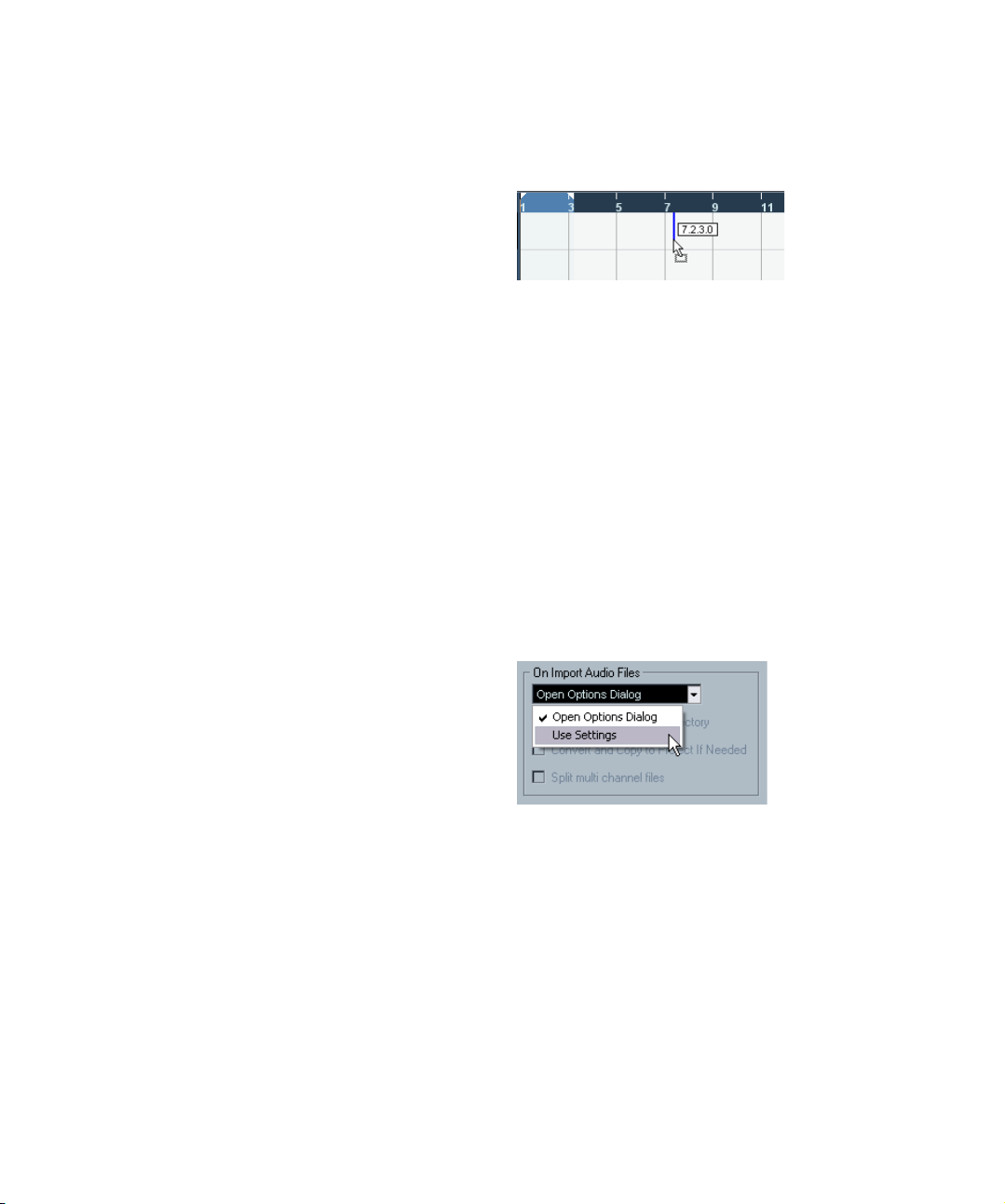
• By dragging files and dropping them on the track at the
desired position.
You can create events by dragging and dropping from the following locations:
• The desktop.
• The MediaBay.
•The Pool.
• The “Find media” dialog.
• The Project window of another open project.
• The Audio Part Editor of any open project.
• The Sample Editor of any open project – press [Ctrl]/[Command] and drag to create an event of the current selection.
While you drag the clip in the Project window, its position will be indicated by a marker line and a numerical position box. See also “By using
drag and drop” on page 175.
Audio file import options
When you are importing audio files there are a number of
options concerning how the files should be treated by Cubase Essential:
• You can choose to copy the file into the audio folder of the
project and have the project make reference to the copied file
rather than the original file. This helps you keep your project
“self-contained”.
• Furthermore, you may want all files in the project to have the
same sample rate and sample size (resolution).
The Preferences (Editing–Audio page) contains a setting
that lets you decide which options, if any, to use. Select
the desired option on the “On Import Audio Files” pop-up:
• Open Options Dialog.
An Options dialog appears when you import, allowing you to select
whether you want to copy the files to the Audio folder and/or convert them
to the project settings. Note:
– When importing a single file of a format other than the project settings,
you can specify which properties (sample rate and/or resolution) should be
changed.
– When importing multiple files at the same time, you can select to convert
the imported files automatically if necessary, i.e. if the sample rate is different than the project’s or the resolution is lower than the project setting.
27
The Project window
Page 28
• Use Settings.
No Options dialog will appear when you import. Instead, you can choose
to make any of the options below the pop-up the standard action(s). Activate any number of the following options to have them performed automatically each time you import audio files:
Option Description
Copy Files to
Working
Directory
Convert and
Copy to Project
If Needed
If files are not already in the project’s audio folder they are
copied there before being imported.
If files are not already in the project’s audio folder they are
copied there before being imported. Furthermore, if the
files have a different sample rate or a lower resolution
than the project settings, they are automatically converted.
Creating parts
Parts are containers for MIDI or audio events. If you record
MIDI, a MIDI part is automatically created, containing the
recorded events. You can also create empty audio or MIDI
parts and later add events to them.
There are two ways to do this:
• Draw a part on a MIDI or audio track with the Pencil tool.
You can also draw parts by pressing [Alt]/[Option] and using the Arrow
tool.
• Double-click with the Arrow tool on a MIDI or audio
track, between the left and right locator.
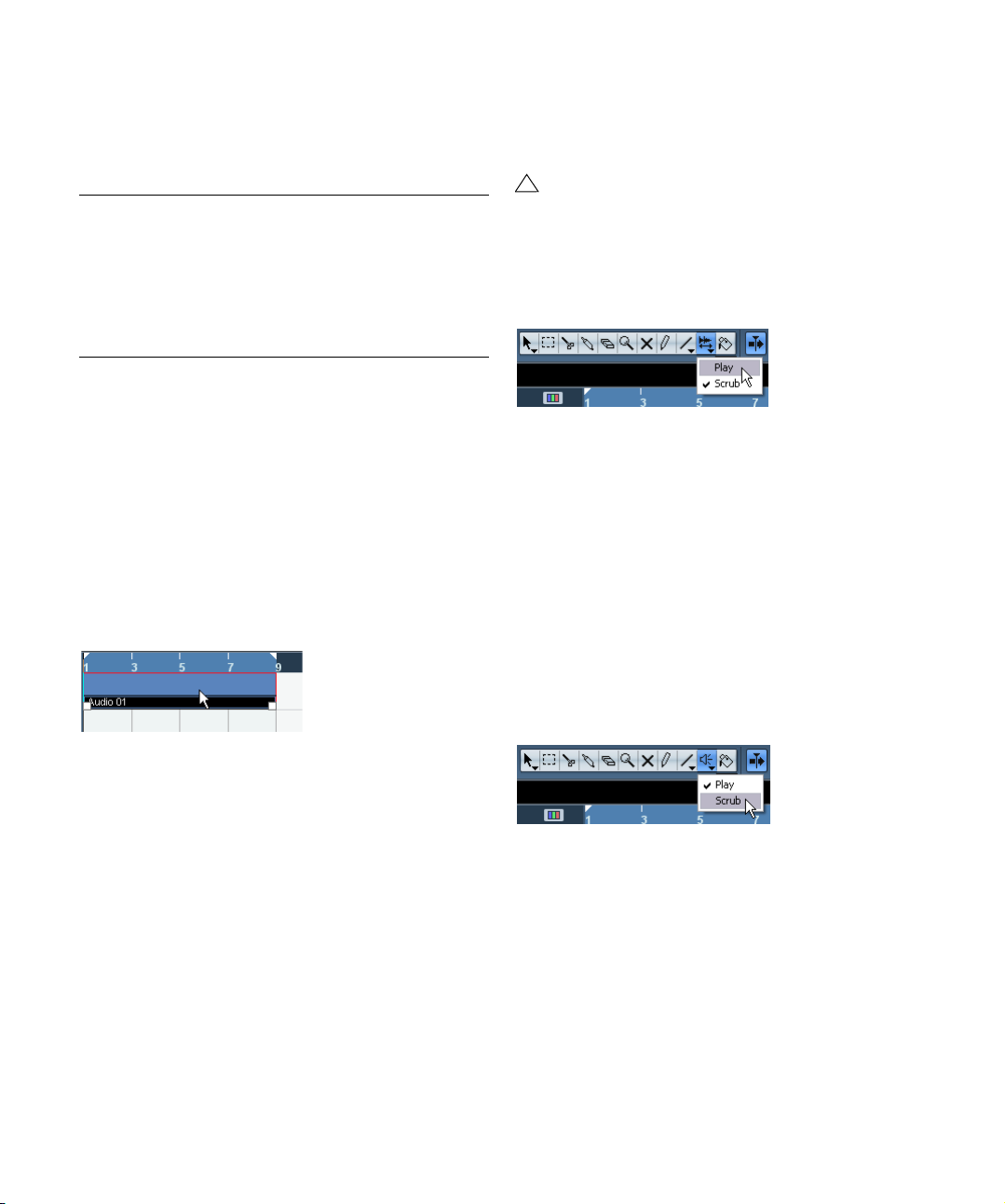
Auditioning audio parts and events
Audio parts and events can be auditioned in the Project
window with the Speaker tool:
!
When auditioning, the Main Mix bus is used.
1. Select the Play tool.
Note that the Play tool and the Scrub tool share the same tool button. If
the tool icon on the toolbar doesn’t show a speaker symbol, first click on
the icon to select it, then click again and select “Play” from the pop-up
menu that appears.
2. Click where you want playback to start, and keep the
mouse button pressed.
Only the track on which you click is played back, starting at the click position.
3. Release the mouse button to stop playback.
Scrubbing
The Scrub tool allows you to locate positions in the audio
by playing back, forwards or backwards, at any speed:
1. Select the Scrub tool.
Note that the Play tool and the Scrub tool share the same tool button. If
the tool icon on the toolbar doesn’t show a “scrub symbol”, first click on
the icon to select it, then click again and select “Scrub” from the pop-up
menu that appears.
To add events to a MIDI part, you use the tools and functions in a MIDI editor (see “The Key Editor – Overview” on
page 227). Adding events to audio parts is done in the
Audio Part Editor (see “Window overview” on page 167)
by pasting or by using drag and drop.
• You can also gather existing audio events into a part, by
using the “Events to Part” function on the Audio menu.
This creates an audio part containing all selected audio events on the
same track. To remove the part and make the events appear as independent objects on the track again, select the part and use the “Dissolve
Part” function on the Audio menu.
The Project window
2. Click at the desired position and keep the mouse but-
ton pressed.
The project cursor is moved to the position at which you click.
3. Drag to the left or right.
The project cursor follows the mouse pointer and the audio is played back.
The speed and pitch of the playback depend on how fast you move the
pointer.
You can adjust the responsiveness of the Scrub function
in the Preferences (Transport–Scrub page).
28
Page 29

• Note that scrubbing can be quite a burden on your system. To avoid playback problems, you will find the “CPU
Saving Scrub Mode” option in the Preferences (Transport–Scrub page).
When you activate this option, scrubbing will be less demanding on the
processor. This can be very useful when scrubbing in a large project,
where the “normal” scrub behavior leads to processing overloads. When
“CPU Saving Scrub Mode” is activated, the effects are disabled for
scrubbing and the resampling quality is lower.
Editing parts and events
This section describes techniques for editing in the Project
window. If not explicitly stated, all descriptions apply to both
events and parts, even though we use the term “event” for
convenience.
Ö When you are using the tools for editing, you can in
many cases get additional functions by pressing modifier
keys (e.g. pressing [Alt]/[Option] and dragging with the
Arrow tool creates a copy of the dragged event).
On the following pages, the default modifier keys are described – you
can customize these in the Preferences (Editing–Tool Modifiers page),
see “Setting up tool modifier keys” on page 326.
Selecting events
Selecting events is done using any of the following
methods:
• Use the Arrow tool.
The standard selection techniques apply.
• Use the Select submenu on the Edit menu.
The options are:
Option Description
All Selects all events in the Project window.
None Deselects all events.
In Loop Selects all events that are partly or wholly between
From Start
to Cursor
From Cursor
to End
All on Selected
Tracks
Select Event This is available in the Sample Editor (see “Window
Left/Right Selection
Side to Cursor
the left and right locator.
Selects all events that begin to the left of the project
cursor.
Selects all events that end to the right of the project
cursor.
Selects all events on the selected track.
overview” on page 151).
These two functions are only used for range selection
editing (see “Creating a selection range” on page 35).
!
Note that these functions work differently when the
Range Selection tool is selected (see “Creating a
selection range” on page 35).
• Select all events on a track by right-clicking in its Track
list and selecting “Select All Events” from the pop-up
menu that appears.
• You can also use the arrow keys on the computer key-
board to select the closest event to the left, right, above or
below.
If you press [Shift] and use the arrow keys, the current selection will be
kept, allowing you to select several events.
• If the option “Auto Select Events under Cursor” is acti-
vated in the Preferences (Editing page), all events on the
selected track(s) that are “touched” by the project cursor
are automatically selected.
This can be helpful when rearranging your project, since it allows you to
select whole sections (on all tracks) by selecting all tracks and moving
the project cursor.
• It is also possible to select ranges, regardless of the
event and track boundaries.
This is done using the Range Selection tool (see “Range editing” on page
35).
• Note that in the Preferences (Editing page), you can
find the option “Use Up/Down Navigation Commands for
selecting Tracks only”.
By default, tracks are selected with the up/down arrow keys on the computer keyboard. However, these are also used for selecting events (see
above) which can lead to confusing results in some cases. Since track selection is a most vital operation in both editing and mixing, you have the option to use the navigation controls for track selection only. The following
applies:
• When this option is deactivated and no event/part is selected
in the Project window, the up/down arrow keys on the computer keyboard are used to step through the tracks in the
Track list – just as you would expect this to work.
• When this option is deactivated and an event/part is selected in
the Project window, the up/down arrow keys still step through
the tracks in the Track list – but on the currently selected track,
the first event/part will automatically be selected as well. If this
is not the desired behavior, you have to activate “Use Up/Down
Navigation Commands for selecting Tracks only”.
• When this option is activated, the up/down arrow keys are
only used to change the track selection – the current event/
part selection in the Project window will not be altered.
29
The Project window
Page 30
• Also in the Preferences (Editing–Tools page), you can
find the Cross Hair Cursor options section.
This allows you to display a cross hair cursor when working in the Project
window and editors, facilitating navigation and editing, especially when
arranging in large projects. You can set up the colors for the line and the
mask of the cross hair cursor, and define its width. The cross hair cursor
works as follows:
• When the Selection tool (or one of its subtools) is selected,
the cross hair cursor appears when you start moving/copying
a part/event, or when using the event trim handles.
• When the Pencil tool, the Scissors tool or any other tool that
makes use of this function is selected, the cross hair cursor appears as soon as you move the mouse over the event display.
• The cross hair cursor is only available for tools where such a
function is of any use. The Mute tool for example does not use
a cross hair cursor, as you have to click directly on an event to
mute it.
Moving events
To move events in the Project window, use the following
methods:
• Click and drag to a new position.
All selected events will be moved, maintaining their relative positions. You
can only drag events to tracks of the same type. If Snap is activated, this
determines to which positions you can move the events (see “Snap” on
page 38).
Note also that you can restrict movement to be either horizontal or vertical
only, by holding down [Ctrl]/[Command] while dragging.
!
You will note that there is a slightly delayed response
when you move an event by dragging. This helps you
avoid accidentally moving events when you click on
them in the Project window. You can adjust this delay with the Drag Delay setting in the Preferences
(Editing page).
• Select the event and edit the Start position in the info line.
• Use the “Move to” functions on the Edit menu.
The following functions are available:
Function Description
Move to Cursor Moves the selected event to the project cursor position. If
Move to Origin Moves the selected events to their original positions, i.e.
there are several selected events on the same track, the
first event will start at the cursor, and the following will be
lined up end-to-start after the first one.
the positions at which they were originally recorded.
Function Description
Move to Front,
Move to Back
This function doesn’t actually change the position of the
events, but moves the selected events to the front or
back, respectively. This is useful if you have overlapping
events, and want to see one that is partially obscured.
For audio events, this is an extra important feature, since
only the visible sections of events will be played back.
Moving an obscured audio event to front (or moving the
obscuring event to back) will allow you to hear the whole
event on playback (see also “Overlapping events” on
page 168).
Note that it is also possible to use the “To Front” function
on the event context menu for this.
• Use the Nudge buttons in the toolbar.
These move the selected events to the left or right. The amount of movement depends on the selected display format (see “The Project Setup di-
alog” on page 22) and the value set on the Grid pop-up menu.
Here, clicking this button will move the event 2 frames to the right.
!
When the Range Selection tool is used, the Nudge
buttons move the selection range (see “Moving and
duplicating” on page 37).
Ö The Nudge buttons are not visible in the toolbar by default.
You can decide which items should be visible by right-clicking in the
toolbar and checking them in the pop-up menu that appears. See “The
Setup dialogs” on page 314 for more information.
Duplicating events
Events can be duplicated in the following ways:
• Hold down [Alt]/[Option] and drag the event to a new
position.
If Snap is activated, this determines to which positions you can copy the
events (see “Snap” on page 38).
!
If you hold down [Ctrl]/[Command] as well, movement direction is restricted to either horizontal or vertical. That means if you drag an event vertically it can
not be moved horizontally at the same time.
30
The Project window
Page 31
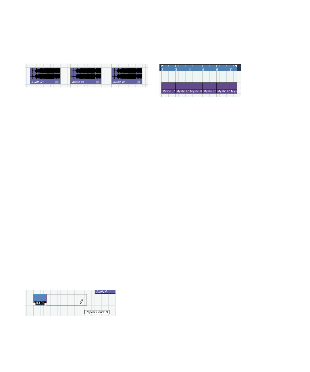
• Audio and MIDI parts can also be duplicated by press-
ing [Alt]/[Option] + [Shift] and dragging.
This creates a shared copy of the part. If you edit the contents of a
shared copy, all other shared copies of the same part are automatically
edited in the same way.
Shared copies are indicated by showing the name in italic text and an
icon in the right corner of the part.
Note:
• When you duplicate audio events, the copies are al-
ways shared. This means that shared copies of audio
events always refer to the same audio clip (see “Audio
processing” on page 142).
• You can convert a shared copy to a real copy by select-
ing “Convert to Real Copy” from the Edit menu. This creates a new version of the clip (that can be edited independently) and adds this to the Pool. Note that no new files are
created by this operation – for that you need to use the
“Bounce Selection” function from the Audio menu.
• Selecting “Duplicate” from the Edit menu creates a
copy of the selected event and places it directly after the
original.
If several events are selected, all of these are copied “as one unit”, maintaining the relative distance between the events.
• Selecting “Repeat…” from the Edit menu opens a dia-
log, allowing you to create a number of copies (regular or
shared) of the selected event(s).
This works just like the Duplicate function, but you can specify the number of copies.
• You can also perform the Repeat function by dragging:
Select the event(s) to repeat, press [Alt]/[Option], click the
handle in the lower right corner of the last selected event
and drag to the right.
The longer to the right you drag, the more copies are created (as shown
by the tooltip).
• Selecting “Fill Loop” from the Edit menu creates a number of copies starting at the left locator and ending at the
right locator.
The last copy is automatically shortened to end at the right locator position.
Using Cut, Copy and Paste
You can cut or copy selected events, and paste them in
again, using the functions on the Edit menu.
• When you paste an event it is inserted on the selected
track, positioned so that its snap point is aligned with the
cursor position.
If the selected track is of the wrong type, the event will be inserted on its
original track. See “Snap” on page 38 for information about the snap point.
• If you use the “Paste at Origin” function, the event is
pasted at its original position (the position from which you
cut or copied it).
Renaming events
By default, audio events show the name of their clip, but
you can enter a separate descriptive name for separate
events if you like. This is done by selecting the event and
typing in a new name in the “Description” field in the info
line.
• You can also give all events on a track the same name
as the track by changing the track name, holding down a
modifier key and pressing [Return].
See “Handling tracks” on page 26.
Splitting events
You can split events in the Project window in the following
ways:
• Click with the Scissors tool on the event you want to
split.
If Snap is activated, this determines the exact split position (see “Snap”
on page 38). You can also split events by pressing [Alt]/[Option] and
clicking with the Arrow tool.
31
The Project window
Page 32

• Select “Split at Cursor” from the Edit menu.
This splits the selected events at the position of the project cursor. If no
events are selected, all events (on all tracks) that are intersected by the
project cursor will be split.
• Select “Split Loop” from the Edit menu.
This splits events on all tracks at the left and right locator positions.
Ö If you split a MIDI part so that the split position intersects one or several MIDI notes, the result depends on the
option “Split MIDI Events” in the Preferences (Editing–
MIDI page).
If the option is activated, the intersected notes will be split (creating new
notes at the beginning of the second part). If it is deactivated, the notes
will remain in the first part, but “stick out” after the end of the part.
Gluing events together
You can glue events together using the Glue Tube tool.
There are three possibilities:
• Clicking on an event with the Glue Tube tool glues it to-
gether with the next event on the track. The events do not
have to touch one another.
The result is a part containing the two events, with one exception: If you
first split an event and then glue the two sections together again (without
moving or editing them first), they become a single event again.
• You can select several events on the same track and
click on one of them with the Glue Tube tool.
A single part is created.
• When you hold down [Alt]/[Option] while clicking on an
event with the Glue Tube tool, this event will be glued together with all following events on this track.
You can change the default key command for this in the Preferences
(Editing–Tool Modifiers page).
To select one of the resizing modes, select the Arrow tool
and then click again on the Arrow tool icon on the toolbar.
This opens a pop-up menu from which you can select one
of the resizing mode options.
The icon on the toolbar will change, indicating the selected resizing mode.
The actual resizing is done by clicking and dragging the
lower left or right corner of the event. If Snap is activated,
the Snap value determines the resulting length (see
“Snap” on page 38).
Normal sizing
Resizing events
Resizing events means to move their start or end positions
individually. In Cubase Essential, there are three types of
resizing:
Resizing type Description
Normal Sizing The contents of the event stay fixed, and the start or end
Sizing Moves
Contents
Sizing Applies
Time Stretch
point of the event is moved to “reveal” more or less of the
contents.
The contents follow the moved start or end of the event
(see the figure below).
The contents will be time stretched to fit the new event
length (see the separate description on “Resizing events
using time stretch” on page 33).
The Project window
Sizing moves contents.
• If several events are selected, all will be resized in the
same way.
32
Page 33
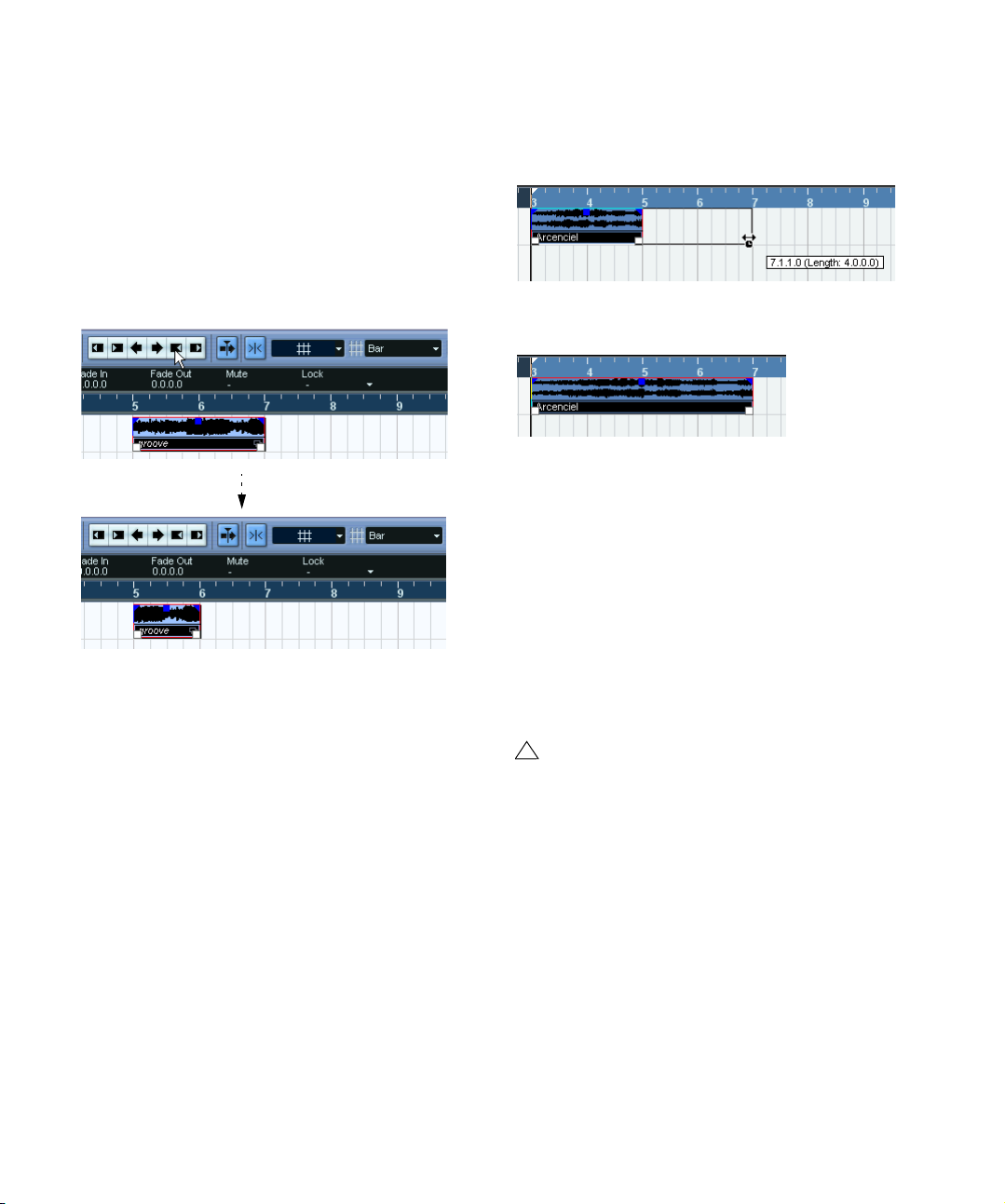
• You can also resize events with the Scrub tool.
This works just the same as when resizing with the Arrow tool, but the
audio under the pointer is played back (scrubbed) while you drag.
• It is also possible to resize events by using the Trim but-
tons (located in the Nudge palette) on the toolbar.
This will move the start or end position of the selected Event(s) by the
amount set on the Grid pop-up menu. The sizing type currently selected
applies to this method too, with the exception of “Sizing Applies Time
Stretch” which is not possible with this method. You can also use key
commands for this (by default, press [Ctrl]/[Command] and use the left
and right arrow key).
Ö Note that the Nudge palette is not visible in the toolbar
by default. See “The Setup dialogs” on page 314 for instructions on how to show and hide items in the toolbar.
3. Click and drag left or right.
When you move the mouse, a tooltip shows the current mouse position
and length of the part. Note that the snap value applies, as with any part
operation.
4. Release the mouse button.
The part is “stretched” or “compressed” to fit the new length.
• For MIDI parts, this means that the note events are
stretched (moved and resized).
Controller data will be moved.
• For audio parts, this means that the events are moved,
and that the referenced audio files are time stretched to fit
the new length.
A dialog box shows the progress of the time stretch operation.
Sliding the contents of an event or part
You can move the contents of an event or part without
changing its position in the Project window. By default, this
is done by pressing [Alt]/[Option]+[Shift], clicking in the
event or part and dragging to the left or right.
Resizing events using time stretch
If you want to resize a part and make its contents “fit” the
new size, you should use this option. Proceed as follows:
1. Click the Arrow icon on the toolbar and select the “Siz-
ing Applies Time Stretch” option from the pop-up menu.
2. Point close to the end point of the part you want to
stretch.
The Project window
33
!
When sliding the contents of an audio event, you
cannot slide past the start or end of the actual audio
clip. If the event plays the whole clip, you cannot
slide the audio at all.
Page 34

Grouping Events
Sometimes it is useful to treat several events as one unit.
This can be done by grouping them: Select the events (on
the same or different Tracks) and select “Group” from the
Edit menu.
• To specify which of these properties should be affected
by the Lock function, use the “Lock Event Attributes” popup menu in the Preferences (Editing page).
Grouped events are indicated by a group icon in the right corner.
If you edit one of the grouped events in the Project window,
all other events in the same group are affected too (if applicable).
Group editing operations include:
• Selecting events.
• Moving and duplicating events.
• Resizing events.
• Adjusting fade-in and fade-out (audio events only, see “Cre-
ating fades” on page 63).
• Splitting events (splitting one event will automatically split any
other grouped events that are intersected by the split position).
• Locking events.
• Muting events (see below).
• Deleting events.
Locking events
If you want to make sure you don’t edit or move an event
by accident, you can lock it. Locking can affect one (or any
combination) of the following properties:
Lock Options Description
Position If this is locked, the event cannot be moved.
Size If this is locked, the event cannot be resized.
Other If this is locked, all other editing of the event is disabled.
This includes adjusting the fades and event volume, processing, etc.
• To lock events, select them and select “Lock…” from
the Edit menu.
The events will be locked according to the options specified in the Preferences.
The padlock symbol indicates that
one or more of the lock options are
activated for the event.
• You can adjust the lock options for a locked event by
selecting it and selecting “Lock…” from the Edit menu
again.
This opens a dialog in which you can activate or deactivate the desired
lock options.
• To unlock an event (turn off all lock options), select it
and select “Unlock” from the Edit menu.
• It is also possible to lock a whole track, by clicking the
padlock symbol in the Track list or in the Inspector.
This disables all editing of all events on the track.
Muting events
To mute individual events in the Project window, proceed
as follows:
• To mute or unmute a single event, click on it with the
Mute tool.
34
The Project window
Page 35

• To mute or unmute several events, select them – either
by using the standard selection techniques, or by using
one of the options on the Select submenu on the Edit
menu – and click on one of the selected events with the
Mute tool.
All selected events will be muted.
• You can also click in an empty area with the Mute tool
and drag a selection rectangle around several events you
want to mute or unmute, and then click on one of them
with the Mute tool.
• You can mute events by selecting them and selecting
“Mute” from the Edit menu.
Similarly, you can unmute the selected events by selecting “Unmute”
from the Edit menu.
• You can also change the mute status of selected events
on the info line.
Muted events can be edited as usual (with the exception
of adjusting fades), but are not played back.
Muted events are “grayed out”.
• You can also mute whole tracks by clicking the Mute
(“M”) button in the Track list, the Inspector or the mixer.
Clicking the Solo (“S”) button for a track mutes all other tracks. Note that
there are two modes for the track solo function:
If the option “Enable Solo on Selected Track” is activated in the Preferences (Editing–Project & Mixer page) and you have soloed a track, selecting another track in the track list will automatically solo that track
instead – the solo state “moves” with the track selection.
If the option isn’t activated, the track you solo stays soloed, regardless of
the selection.
Removing events
To remove an event from the Project window, use any of
the following methods:
• Click on the event with the Eraser tool.
Note that if you press [Alt]/[Option] while you click, all following events
on the same track will be deleted, but not the event you clicked and all
events before it.
• Select the event(s) and press [Backspace], or select
“Delete” from the Edit menu.
Creating new files from events
An audio event plays a section of an audio clip, which in
turn refers to one or more audio files on the hard disk.
However, in some situations you may want to create a new
file that consists only of the section played by the event.
This is done with the function “Bounce Selection” on the
Audio menu:
1. Select one or several audio events.
2. Set up fade in, fade out and event volume (on the info
line or using the volume handle) as desired.
These settings will be applied to the new file. For details on fades and
event volume, see “Creating fades” on page 63.
3. Select “Bounce Selection” from the Audio menu.
You are asked whether you want to replace the selected event or not.
• If you click “Replace”, a new file is created, containing
only the audio in the original event. A clip for the new file is
added to the Pool, and the original event is replaced by a
new event playing the new clip.
• If you click “No”, a new file is created and a clip for the
new file is added to the Pool.
The original event is not replaced.
You can also apply the Bounce Selection function to an
audio part. In that case, the audio from all events in the
part will be combined into a single audio file. If you choose
“Replace” when asked, the part will be replaced with a
single audio event playing a clip of the new file.
Range editing
Editing in the Project window isn’t necessarily restricted
to handling whole events and parts. You can also work
with selection ranges, which are independent from the
event/part and track boundaries.
Creating a selection range
To make a selection range, drag with the Range Selection
tool.
35
The Project window
Page 36

When the Range Selection tool is selected, the Select
submenu on the Edit menu has the following items for
making selection ranges:
Option Description
All Makes a selection that covers all tracks, from the start of
None Removes the current selection range.
In Loop Makes a selection between the left and right locator, on
From Start
to Cursor
From Cursor
to End
All on Selected
Tracks
Select Event This is available in the Sample Editor (see “Using the Se-
Left Selection
Side to Cursor
Right Selection
Side to Cursor
the project to the end (as defined by the Length setting in
the Project Setup dialog).
all tracks.
Makes a selection on all tracks, from the start of the
project to the project cursor.
Makes a selection on all tracks, from the project cursor to
the end of the project.
Only used for event selection (see “Selecting events” on
page 29).
lect menu” on page 156).
Moves the left side of the current selection range to the
project cursor position.
Moves the right side of the current selection range to the
project cursor position.
• Double-clicking on an event with the Range Selection
tool creates a selection range encompassing the event.
If you hold down [Shift] you can double-click several events in a row, and
the selection range will expand to encompass them all. Double-clicking a
second time on an event opens it for editing in the Sample Editor.
Adjusting the size of the selection range
You can adjust the size of a selection range in the following ways:
• By dragging its edges.
The pointer takes the shape of a double arrow when you move it over an
edge of the selection range.
• By holding down [Shift] and clicking.
The closest selection range edge will be moved to the position at which
you clicked.
• By adjusting the selection range start or end position on
the info line.
• By using the Trim buttons on the toolbar.
The left Trim buttons will move the start of the selection range and the
right buttons will move the end. The edges will be moved by the amount
specified on the Grid pop-up.
Clicking this Trim button…
…will move the start of the selection range to the right by 1beat.
• By using the Nudge buttons on the toolbar.
These will move the whole selection range to the left or the right. The
amount of movement depends on the selected display format (see “The
Project Setup dialog” on page 22) and the value specified on the Grid
pop-up menu.
!
Note that the contents of the selection are not
moved – using the Nudge buttons is the same as adjusting the start and end of the selection range at the
same time, by the same amount.
Ö The Trim buttons and the Nudge buttons are located
in the Nudge palette, which is not visible in the toolbar by
default.
See “The Setup dialogs” on page 314 for instructions on how to show
and hide items in the toolbar.
36
The Project window
Page 37
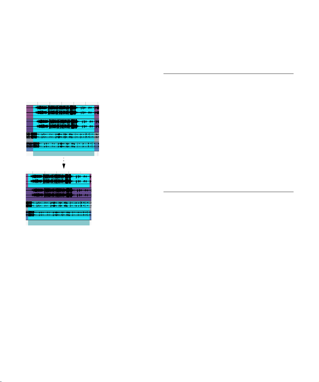
Making selection ranges for several non-contiguous
tracks
You can create selection ranges that cover several tracks
by pressing [Alt]/[Option]+[Shift]. However, it is also possible to exclude tracks from a selection range:
1. Create a selection range from the first to the last de-
sired track.
2. Press [Alt]/[Option] and click in the selection range on
the tracks you want to exclude from the selection.
3. In the same manner, you can add a track to the selec-
tion range by [Alt]/[Option]-clicking in the selection range
area on the track.
Moving and duplicating
• To move a selection range, click and drag it to a new
position.
This will move the contents of the selection range to the new position. If
the range intersected events or parts, these will be split before moving,
so that only the sections within the selection range are affected.
• To duplicate a selection range, hold down [Alt]/[Option]
and drag.
You can also use the Duplicate, Repeat and Fill Loop functions, just as
when duplicating events (see “Duplicating events” on page 30).
Using Cut, Copy and Paste
When working with selection ranges, you can either use
Cut, Copy and Paste on the Edit menu, or use the functions “Cut Time” and “Paste Time” on the Range submenu
on the Edit menu. These work differently to their related
functions on the Edit menu:
Function Description
Cut Cuts out the data in the selection range and moves it to
Copy Copies the data in the selection range to the clipboard.
Paste Pastes the clipboard data at the start position and track
Paste at Origin Pastes the clipboard data back at its original position. Ex-
Cut Time Cuts out the selection range and moves it to the clip-
Paste Time Pastes the clipboard data at the start position and track
Paste Time at
Origin
the clipboard. The selection range is replaced by empty
track space in the Project window, meaning that events
to the right of the range keep their positions.
of the current selection. Existing events are not moved to
make room for the pasted data.
isting events are not moved to make room for the pasted
data.
board. Events to the right of the removed range are
moved to the left to fill out the gap.
of the current selection. Existing events are moved to
make room for the pasted data.
Pastes the clipboard data back at its original position. Existing events are moved to make room for the pasted data.
Deleting selection ranges
Again, you can either use “regular” Delete or “Delete Time”:
• If you use the Delete function on the Edit menu (or press
[Backspace]), the data within the selection range is replaced by empty track space.
Events to the right of the range keep their position.
• If you use “Delete Time” on the Edit menu’s Range submenu, the selection range is removed and events to the
right are moved to the left to close up the gap.
37
The Project window
Page 38

Other functions
On the Range submenu on the Edit menu, you will find
three more range editing functions:
Function Description
Split Splits any events or parts that are intersected by the selec-
Crop All events or parts that are partially within the selection
Insert Silence Inserts empty track space from the start of the selection
tion range, at the positions of the selection range edges.
range are cropped, that is, sections outside the selection
range are removed. Events that are fully inside or outside
the selection range are not affected.
range. The length of the silence equals the length of the
selection range. Events to the right of the selection range
start are moved to the right to “make room”. Events that
are intersected by the selection range start are split, and
the right section is moved to the right.
Options
Snap
The Snap function helps you to find exact positions when
editing in the Project window. It does this by restricting
horizontal movement and positioning to certain positions.
Operations affected by Snap include moving, copying,
drawing, sizing, splitting, range selection, etc.
• You turn Snap on or off by clicking the Snap icon in the
toolbar.
Snap activated.
Ö When you are moving audio events with Snap activated, it isn’t necessarily the beginning of the event that is
used as Snap position reference. Instead, each audio
event has a snap point, which you can set to a relevant position in the audio (such as a downbeat, etc.).
The snap point is preferably set in the Sample Editor since it allows for a
higher degree of precision (see “Adjusting the snap point” on page 155).
You can however also set the snap point directly in the Project window,
in the following way:
1. Select an event.
2. Place the project cursor at the desired position within
the selected audio event.
3. Pull down the Audio menu and select “Snap Point To
Cursor”.
The snap point is set at the cursor position.
The snap point for an event is displayed as a blue line in the Project
window.
Exactly how Snap works depends on which mode is selected on the Snap mode pop-up menu.
The following sections describe the different Snap modes:
Grid
In this mode, the Snap positions are set with the Grid
pop-up menu to the right. The options depend on the display format selected for the ruler. For example, if the ruler
is set to show bars and beats, the grid can be set to bars,
beats or the quantize value set with the next pop-up menu
to the right. If a time or frame-based ruler format is selected, the grid pop-up menu will contain time or framebased grid options, etc.
When Seconds is selected as ruler format, the grid pop-up menu contains time-based grid options.
38
The Project window
Page 39

Grid Relative
When you move events and parts in this mode they will not
be “magnetic” to the grid. Rather, the grid determines the
step size for moving the events. This means that a moved
event will keep its original position relative to the grid.
For example, if an event starts at the position 3.04.01 (one
beat before bar 4), Snap is set to Grid Relative and the
Grid pop-up is set to “Bar”, you can move the event in
steps of one bar – to the positions 4.04.01, 5.04.01 and
so on. The event will keep its relative position to the grid,
i.e. stay one beat before the bar lines.
• This only applies when dragging existing events or parts
– when you create new events or parts this mode works
like the Grid mode.
Events
In this mode, the start and end positions of other events
and parts become “magnetic”. This means that if you drag
an event to a position near the start or end of another
event, it is automatically aligned with the start or end of the
other event. For audio events, the position of the snap
point is also magnetic (see “Adjusting the snap point” on
page 155).
• Note that this includes marker events on the marker track.
This allows you to snap events to marker positions, and vice versa.
Shuffle
Shuffle mode is useful when you want to change the order
of adjacent events. If you have two adjacent events and
drag the first one to the right, past the second event, the
two events will change places.
The same principle works when changing the order of
more than two events:
12345
Dragging event 2 past event 4…
52431
…changes the order of events 2, 3 and 4.
Magnetic Cursor
When this mode is selected, the project cursor becomes
“magnetic”. Dragging an event near the cursor causes the
event to be aligned with the cursor position.
Grid + Cursor
This is a combination of the “Grid” and “Magnetic Cursor”
modes.
Events + Cursor
This is a combination of the “Events” and “Magnetic Cursor” modes.
Events + Grid + Cursor
This is a combination of the “Events”, “Grid” and “Magnetic Cursor” modes.
Snap to Zero Crossing
When this option is activated in the Preferences (Editing–
Audio page), splitting and sizing of audio events is done at
zero crossings (positions in the audio where the amplitude
is zero). This helps you avoid pops and clicks which might
otherwise be caused by sudden amplitude changes.
!
39
The Project window
This setting affects all windows in all open projects –
with the exception of the Sample Editor (which has
its own “Use Snap” button for this).
Page 40

Autoscroll
Autoscroll activated
When this option is activated, the waveform display will
scroll during playback, keeping the project cursor visible
in the window.
• If the option “Stationary Cursors” is activated in the
Preferences (Transport page), the project cursor will be
positioned in the middle of the screen (if possible).
40
The Project window
Page 41

4
Playback and the Transport panel
Page 42
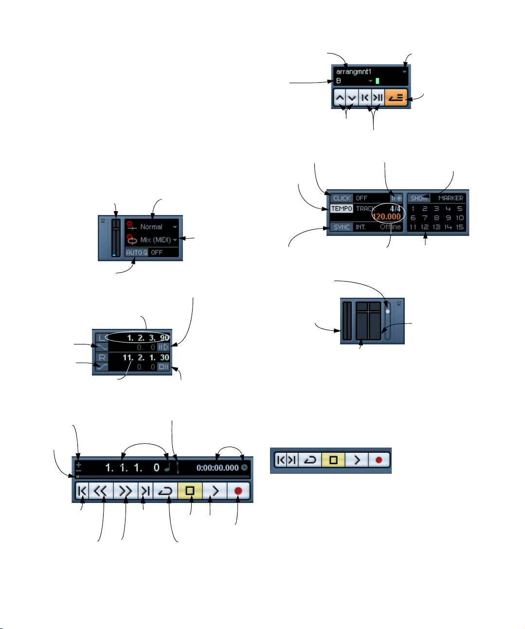
Background
This chapter describes the various methods available for
controlling Playback and Transport functions in Cubase
Essential.
Active Arranger
chain
Current Arranger
item
Arranger Selector
Activate Arranger
Mode
The Transport panel
Below you can find a brief description of each item on the
Transport panel.
The pictures below show the Transport panel with all controls visible and in their default position. The Transport
panel is divided into sections, from left to right.
CPU load and Disk Cache meters
Activates Auto Quantize
Preroll setting and on/off switch
Left locator: record start point, punch
in point and beginning of Cycle
Activates
punch in
Activates
punch out
Right locator: punch out
point and end of Cycle
Nudge position
right/left
Position
slider
Primary Time Display
and format pop-up
Record mode pop-up menu
Postroll setting
and on/off switch
Exchange time formats
Secondary Time Display
and format pop-up
Cycle Record mode
pop-up menu
Previous/Next Arranger items
First/Last repeat of current Arranger item
Metronome click on/off Show Markers (opens
Tempo track
on/off
Synchronization
on/off
Output Level Control
MIDI In Activity
(left meter)/
MIDI Out activity
Audio input activity and Clipping indicator (Default Input channel)
Precount on/off
The tempo and time
signature display
Marker window)
Jump to Marker
Audio output activity and Clipping
indicator (top)
Ö Note that the Output Activity and Clipping indicator as
well as the Output Level Control refer to the Main Mix
Output bus as defined on the Outputs tab in the VST
Connections window.
• The main Transport functions (Cycle/Stop/Play/Record)
can also be shown on the toolbar.
Go to previous
marker or
project start
Fast forwardRewind
Go to next
marker or
project end
Play
Stop
Cycle on/off
In addition, various play options are available on the Transport menu.
Record
42
Playback and the Transport panel
Page 43

Hiding and showing the Transport Panel
The Transport panel is shown by default when you launch
a new project. To hide or show it, select “Transport Panel”
on the Transport menu (or use a key command – by default [F2]).
About Preroll and Postroll
These items are described in the chapter “Recording”,
see “About Preroll and Postroll” on page 59.
Changing the Transport panel setup
You can customize the appearance of the Transport panel
by right-clicking anywhere on the panel and selecting/deselecting the desired options on the pop-up menu that appears.
This is described in detail in the section “Customizing via
the setup context menus” on page 314.
The numeric keypad
In the default Key Command settings, various Transport
panel operations are assigned to the numeric keypad on
the computer keyboard. The keypads are slightly different
on PC and Macintosh computers:
Numeric Key Function
[Enter] Play
[+] Fast Forward
[-] Rewind
[*] Record
[÷] (Win)/[/] (Mac) Cycle On/Off
[,] Return to Zero
[0] Stop
[1] Go to Left Locator
[2] Go to Right Locator
[3-9] Go to marker 3 to 9
Operations
Setting the project cursor position
There are several ways to move the project cursor position:
• By using Fast Forward and Rewind.
• By dragging the project cursor in the lower part of the
ruler.
• By clicking in the ruler.
Double-clicking in the ruler moves the cursor and starts/stops playback.
• If the option “Locate when Clicked in Empty Space” is
activated in the Preferences (Transport page) you can
click anywhere in an empty section of the Project window
to move the cursor position.
• By changing the value in any of the position displays.
• By using the position slider above the transport buttons
in the Transport panel.
The range of the slider relates to the Length setting in the Project Setup
dialog. Hence, moving the slider all the way to the right will take you to
the end of the project.
• By using markers (see “About markers” on page 82).
• By using playback options (see “Playback functions” on
page 45).
• By using the Arranger function (see “The Arranger
track” on page 70).
• By using functions on the Transport menu.
The following functions are available:
Function Description
Locate Selection/
Locate Selection
End
Locate Next/
Previous Marker
Locate Next/
Previous Event
Moves the project cursor to the beginning or end of the
current selection. For this to be available, you must
have selected one or more events or parts, or made a
selection range.
This moves the project cursor to the closest marker to
the right or left (see “About markers” on page 82).
This moves the project cursor forwards or backwards
respectively, to the closest beginning or end of any
event on the selected track(s).
Ö If Snap is activated when dragging the project cursor,
the Snap value is taken into account. This is helpful for
finding exact positions quickly.
43
Playback and the Transport panel
Page 44

Ö There are also numerous key commands available for
moving the project cursor (in the Transport category in the
Key Commands dialog).
For example, you can assign key commands to the “Step Bar” and “Step
Back Bar” functions, allowing you to move the project cursor in steps of
one bar, backwards and forwards.
About the Transport panel display formats
Primary time display (left) and secondary time display (right).
The time unit shown in the ruler can be independent from
the time unit shown in the main time display on the Transport panel. This means that you can display timecode in
the transport position display and bars and beats in the
ruler, for example. In addition, there is a secondary time
display to the right of the primary time display which is
also independent, giving you three different time units
shown at the same time.
The following rules apply:
• If you change the time format of the primary time display
on the Transport panel, the time format of the ruler will be
changed as well.
This is the same as changing the display format in the Project Setup.
Therefore, to have different display formats in the ruler and the main time
display you should change the format in the ruler.
• The primary time display format is set on the pop-up
menu to the right in the main position display.
• This setting also determines the time format displayed
for the left and right locators on the Transport panel.
• The secondary time display is completely independent,
and the display format is set on the pop-up menu to the
right in the secondary time display.
• You can swap time formats between the primary and
secondary time displays by clicking the double arrow symbol between them.
The left and right locators
The left and right locators are a pair of position markers
used for specifying punch-in and punch-out positions during recording, and as boundaries for cycle playback and
recording.
Ö When cycle mode is activated on the Transport panel,
the area between the left and right locator will be repeated
(cycled) on playback.
However, if the right locator is positioned before the left, this will work as
a “jump” or “skip mode” – when the project cursor reaches the right locator it will immediately jump to the left locator position and continue
playback from there.
There are several ways to set locator positions:
• To set the left locator, press [Ctrl]/[Command] and click
at the desired position in the ruler.
Similarly, pressing [Alt]/[Option] and clicking in the ruler sets the right locator. You can also drag the locator “handles” directly in the ruler.
The locators are indicated by the “flags” in the ruler. The area between
the locators is highlighted in the ruler and in the Project window (see
“Appearance” on page 317). Note that if the right locator is before the
left locator, the color of the ruler between the locators will change (from
blue to red).
• Click and drag in the upper half of the ruler to “draw” a
locator range.
If you click on an existing locator range, you can drag to move it.
• Pressing [Ctrl]/[Command] and pressing [1] or [2] on
the numeric keypad sets the left or right locator to the
project cursor position.
Similarly, you can press [1] or [2] on the numeric keypad (without [Ctrl]/
[Command]) to set the project cursor position to the left or right locator
position. Note that these are default key commands – you can change
these if you like.
• By creating cycle markers you can store any number of
left and right locator positions, which can be recalled by
simply double-clicking on the corresponding marker (see
“About cycle markers” on page 83).
• The “Locators to Selection” item on the Transport menu
(default key command [P]) sets the locators to encompass
the current selection.
This is available if you have selected one or several events or made a selection range.
44
Playback and the Transport panel
Page 45
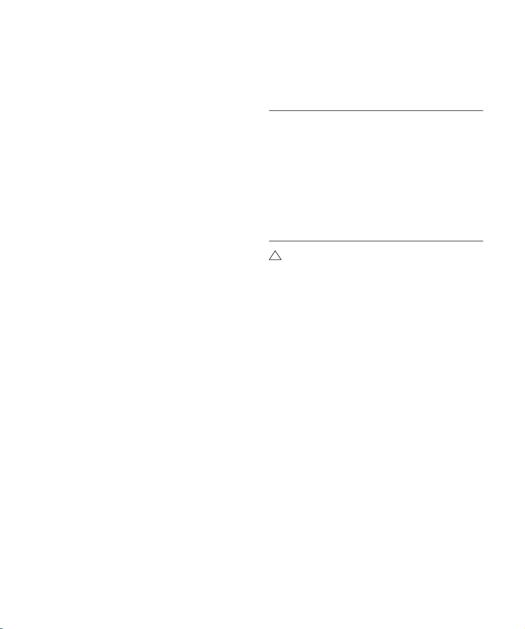
• You can also adjust the locators numerically on the
Transport panel.
Clicking the L/R buttons in the locator section on the Transport panel will
move the project cursor to the respective locator. If you press [Alt]/[Option] and click the L or R button, the corresponding locator will be set to
the current project cursor position.
Options and Settings
The “Return to Start Position on Stop”
preference
This setting is found on the Transport page in the Preferences (found on the File menu under Windows, or on the
Cubase Essential menu under Mac OS X).
• If “Return to Start Position on Stop” is activated when
you stop playback, the project cursor will automatically return to the position where recording or playback last
started.
• If “Return to Start Position on Stop” is deactivated, the
project cursor will remain at the position where you stop
playback.
Pressing Stop again will return the project cursor to the position where
recording or playback last started.
About track disable/enable
For audio tracks, the track context menu contains an item
named “Disable Track”. This shuts down all disk activity
for the track, as opposed to using Mute, which merely
turns down the output volume for a track. For example, if
you often record “alternative takes” you can easily build up
a large number of takes on different tracks. Even though
these tracks are muted, they are actually still “playing
back” from the hard disk during playback. This puts an unnecessary load on your disk system, so using “Disable
Track” is recommended for such situations.
• Select “Disable Track” for tracks that you want to keep in
the project for later use but don’t want to play back now.
Select “Enable Track” from the track context menu to re-enable disabled
tracks.
Playback functions
Apart from the standard transport controls on the Transport panel, you can also find a number of functions that
can be used to control playback on the Transport menu.
The items have the following functionality:
Option Description
Play from Selection
Start/End
Play until Selection
Start/End
Play until Next
Marker
Play Selection
Range
Loop Selection This activates playback from the start of the current
!
The functions listed above (except “Play until Next
Activates playback from the beginning or end of
the current selection.
Activates playback two seconds before the start or
end of the current selection and stops at the selection start or end, respectively.
This activates playback from the project cursor and
stops at the next marker.
This activates playback from the start of the current
selection and stops at the selection end.
selection and keeps starting over again when
reaching the selection end.
Marker”) are only available if you have selected one
or more events or made a selection range.
Ö In the Preferences dialog (Editing–Audio page) you
will find the option “Treat Muted Audio Events like Deleted”. When you activate this option, any events overlapped by a muted event will become audible.
About Chase
Chase is a function that makes sure your MIDI instruments
sound as they should when you locate to a new position
and start playback. This is accomplished by the program
transmitting a number of MIDI messages to your instruments each time you move to a new position in the
project, making sure all MIDI devices are set up correctly
with regard to program change, controller messages
(such as MIDI Volume), etc.
For example, let’s say you have a MIDI track with a program change event inserted at the beginning. This event
makes a synth switch to a piano sound.
At the beginning of the first chorus you have another program change event which makes the same synth switch to
a string sound.
45
Playback and the Transport panel
Page 46
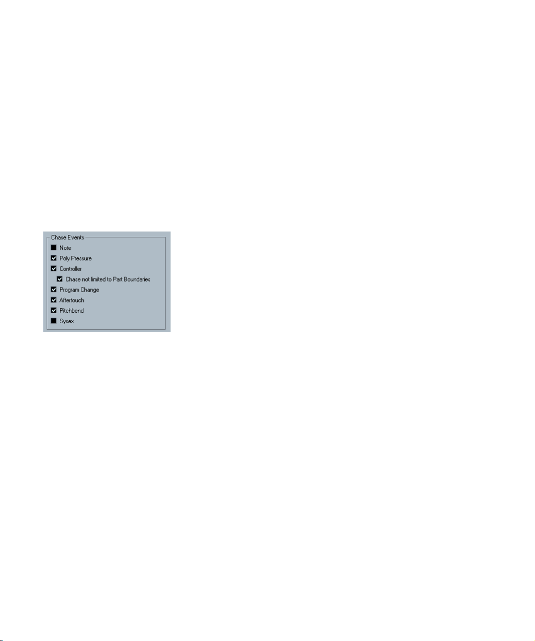
You now play back the song. It begins with the piano
sound and then switches to the string sound. In the middle
of the chorus you stop and rewind to some point between
the beginning and the second program change. The synth
will now still play the string sound although in this section
it really should be a piano!
The Chase function takes care of that. If program change
events are set to be chased, Cubase Essential will track
the music back to the beginning, find the first program
change and transmit it to your synth, setting it to the correct sound.
The same thing can apply to other event types as well. The
Chase Events settings in the Preferences (MIDI page) determine which event types will be chased when you locate
to a new position and start playback.
Ö Event types for which the checkbox is activated here
will be chased.
• In the Chase Events section of the Preferences (MIDI
page), you will find the option “Chase not limited to Part
Boundaries”.
When you activate this option, MIDI controllers are also chased outside
the part boundaries, i.e. the Chase will be performed on the part touched
by the cursor as well as on all the parts to the left of it. Please note that
this option should be deactivated for very large projects, as it considerably slows down operations such as positioning and soloing. When you
deactivate this option, the MIDI controllers are only chased within the
parts under the position cursor.
Playback and the Transport panel
46
Page 47

5
Recording
Page 48

Background
This chapter describes the various recording methods
that you can use in Cubase Essential. As it is possible to
record both audio and MIDI tracks, both recording methods are covered in this chapter.
Before you start
This chapter assumes that you are reasonably familiar with
certain basic recording concepts, and that the following
initial preparations have been made:
• You have properly set up, connected and calibrated
your audio hardware.
• You have opened a project and set the project setup
parameters to your specifications.
Project setup parameters determine the record format, sample rate,
project length etc. that affect the audio recordings you make during the
course of the project. See “The Project Setup dialog” on page 22.
• If you plan to record MIDI, your MIDI equipment should
be set up and connected correctly.
Basic recording methods
This section describes the general methods used for recording. However, there are additional preparations and
procedures that are specific to audio and MIDI recording
respectively. Make sure to read these sections before you
start recording (see “Audio recording specifics” on page
50 and “MIDI recording specifics” on page 54).
Record-enabling a track
Cubase Essential can record on a single track or on several tracks (audio and/or MIDI) simultaneously. To make a
track ready for recording, click the Record Enable button
for the track in the Track list, in the Inspector or in the
mixer. When activated, the buttons turn red, indicating
record ready mode.
Record Enable in the Inspector, Track list and mixer
Ö If the option “Enable Record on Selected Track” is activated in the Preferences (Editing–Project & Mixer page),
tracks are automatically record-enabled when you select
them in the Track list.
Ö The exact number of audio tracks you can record simultaneously depends on your computer CPU and hard
disk performance.
In the Preferences (VST page), you can find the option “Warn on Processing Overloads”. When this is activated, a warning message will be
displayed as soon as the CPU clip indicator (on the Transport panel)
lights up during recording.
Manually activating recording
You activate recording by clicking the Record button on
the Transport panel or toolbar or by using the corresponding key command (by default [*] on the numeric keypad).
Recording can be activated in Stop mode (from the current
cursor position or from the left locator) or during playback:
• If you activate recording in Stop mode, and the option
“Start Record at Left Locator” is activated on the Transport menu, recording will start from the left locator.
The preroll setting or the metronome count-in will be applied (see “About
Preroll and Postroll” on page 59).
• If you activate recording in Stop mode, and “Start Record
at Left Locator” is deactivated, recording will start from the
current project cursor position.
• If you activate recording during playback, Cubase Essential will immediately enter Record mode and start recording from the current project cursor position.
This is known as “manual punch in”.
48
Recording
Page 49

Activating recording in Sync mode
If you are synchronizing the Cubase Essential transport to
external equipment (Sync is activated on the Transport
panel) and you activate recording, the program will go into
“record ready” mode (the record button on the Transport
panel will light up). Recording then starts when a valid
timecode signal is received (or when you click the Play
button). See the chapter “Synchronization” on page 278
for more information.
• If the Punch Out button is activated on the Transport
panel, recording will be deactivated when the project cursor reaches the right locator.
This is known as “automatic punch out”. By combining this with automatic punch in, you can set up a specific section to record – again very
useful if you want to replace a certain part of a recording. See also “Stop
after Automatic Punch Out” on page 59.
Automatically activating recording
Cubase Essential can automatically switch from playback
to recording at a given position. This is known as “automatic punch in”. A typical use for this would be if you need
to replace a section of a recording, and want to listen to
what is already recorded, up to the recording start position.
1. Set the left locator to the position where you want re-
cording to start.
2. Activate the Punch In button on the Transport panel.
Punch In activated
3. Activate playback from some position before the left
locator.
When the project cursor reaches the left locator, recording is automatically activated.
Stopping recording
Again, this can be done automatically or manually:
• If you click the Stop button on the Transport panel (or
use the corresponding key command, by default [0] on the
numeric keypad), recording is deactivated and Cubase
Essential goes into Stop mode.
• If you click the Record button (or use the key command
for recording, by default [*]), recording is deactivated but
playback continues.
This is known as “manual punch out”.
Punch In and Out activated
Cycle recording
Cubase Essential can record and play back in a cycle – a
loop. You specify where the cycle starts and ends by setting the left and right locators. When the cycle is active,
the selected section is seamlessly repeated until you hit
Stop or deactivate cycle mode.
• To activate cycle mode, click the cycle button on the
Transport panel.
If you now start playback, the section between the left and right locator is
repeated indefinitely until you stop.
Cycle activated
• To record in cycle mode, you can start recording from
the left locator, from before the locators or from within the
cycle, in Stop mode or during playback.
As soon as the project cursor reaches the right locator, it will jump back
to the left locator and continue recording a new lap.
• The results of cycle recording depend on the selected
cycle record mode and are different for audio (see “Re-
cording audio in cycle mode” on page 54) and MIDI (see
“Recording MIDI in cycle mode” on page 57).
49
Recording
Page 50

Audio pre-record
This feature allows you to capture up to 1 minute of any incoming audio you play in Stop mode or during playback,
“after the fact”. This is possible because Cubase Essential
can capture audio input in buffer memory, even when not
recording.
Proceed as follows:
1. Open the Preferences (Record-Audio page).
2. Specify a time (up to 60 seconds) in the “Audio Pre-
Record Seconds” field.
This activates the buffering of audio input, making Pre-Record possible.
3. Make sure an audio track is record-enabled and re-
ceives audio from the signal source.
4. When you have played some audio material you want
to capture (either in Stop mode or during playback), click
the Record button.
5. After a few seconds stop the recording.
An audio event is created, starting at where the cursor position was
when you activated recording. This means that if you were in stop mode,
and the cursor was at the beginning of the project, you may have to move
the event to the right in the next step. If you were playing along to a
project you should leave the event where it is.
6. Select the Arrow tool and place the cursor on the bot-
tom left edge of the event so that a double arrow appears,
then click and drag to the left.
Now the event is extended and the audio you played before activating
record is inserted – this means that if you played along during playback,
the captured notes will end up exactly where you played them in relation
to the project.
Audio recording specifics
Selecting a recording file format
The format for recorded files is set in the Project Setup dialog on the Project menu. There are three settings: sample
rate, record format (bit depth) and record file type. While
the sample rate is set once and for all when you start working on a new project, the bit depth and file type can be
changed at any time.
Record file type
The Record File Type setting determines which type of
files will be created when you record:
File type Description
Wave File Wave files have the extension “.wav” and are a common
AIFF File Audio Interchange File Format, a standard defined by Ap-
Record format (bit depth)
The available options are 16 bit and 24 bit. Use the following guidelines:
• Normally, select the record format according to the bit
depth delivered by your audio hardware.
For example, if your audio hardware has 20 bit A/D converters (inputs),
you may want to record at 24 bit resolution to capture the full bit depth.
On the other hand, if your hardware has 16 bit inputs, it’s pointless to
record with a higher bit depth – this will only make the audio files larger,
with no difference in audio quality.
• The higher the bit depth, the larger the files and the
more strain is put on the disk system.
If this is an issue, you may want to lower the record format setting.
file format on the PC platform.
ple Inc. AIFF files have the extension “.aif” and are used
on most computer platforms. AIFF files can contain embedded text strings (see below).
The recording was activated at the start of bar 9. This is indicated by a
blue line in the audio event.
Recording
50
!
For further information on the options in the Project
Setup dialog, see “The Project Setup dialog” on
page 22.
Page 51

Setting up the track
Creating a track and selecting the channel configuration
Audio tracks can be configured as mono or stereo tracks.
This allows you to record or import a file containing multiple channels and treat it as one entity, with no need to split
it up into several mono files etc. The signal path for an audio track maintains its channel configuration all the way
from the input bus, via EQ, level and other mixer settings
to the output bus.
You specify the channel configuration for a track when you
create it:
1. Select “Add Audio Track” from the Track list context
menu or the Project menu (or double-click in an empty
area of the Track list when an audio track is selected –
when a MIDI track is selected, double-clicking in the Track
list creates a new MIDI track).
A dialog appears with a channel configuration pop-up menu.
2. Select the desired format from the pop-up menu.
You can choose between mono and stereo.
• The Browse item in this dialog allows you to browse
your disk(s) for created Track Presets, which can be used
as a basis (or template) for tracks.
This is described in detail in the chapter “Track Presets” on page 195.
3. Click OK.
A track appears, set to the specified channel configuration. In the mixer,
a corresponding channel strip appears. You cannot change the channel
configuration for a track.
Selecting an input bus for a track
Here we assume that you have added and set up the required input busses (see “Setting up busses” on page
10). Before you record, you need to specify from which in-
put bus the track should record. You can do this in the Inspector:
• Select an input bus on the Input Routing pop-up menu
in the top section.
As described in the section “The Inspector” on page 18, the Inspector
shows the settings for the selected track. You show or hide the Inspector
by clicking the “Show/Hide Inspector” button on the Project window
toolbar.
Click here to show/hide the Inspector.
Click here to select an input bus for the track.
Setting input levels
When recording digital sound, it’s important to set the input levels correctly – loud enough to ensure low noise and
high audio quality, but not so loud that clipping (digital distortion) occurs.
Clipping typically occurs in the audio hardware when a
too loud analog signal is converted to digital in the hardware’s A/D converters.
You need to check the level at the channel strip for the
track on which you are recording:
1. Locate the channel strip for the track you’re about to
record on.
2. Activate monitoring for the channel by clicking the
speaker button next to the fader.
When monitoring is activated, the meter shows the level of the incoming
audio signal.
3. Play the audio source that you want to record and
check the level meter for the channel.
51
Recording
Page 52

4. Adjust the output level of your audio source so that the
meters go reasonably high without reaching 0.0 dB.
Check the numerical peak level indicator below the meter in the bus
channel strip. To reset the peak level indicator, click on it.
Ö You must adjust the output level of the audio source –
you cannot use the faders in Cubase Essential to adjust
the input level!
Ö An alternative way of checking the input levels would
be to use the control panel for your audio hardware (if it
features input level meters). It may also be possible to adjust the input level in the control panel.
See the documentation of your audio hardware for details.
Monitoring
In this context, “monitoring” means listening to the input
signal during recording. There are three fundamentally different ways to do this: via Cubase Essential, externally (by
listening to the signal before it reaches Cubase Essential),
or by using ASIO Direct Monitoring (which is a combination of both other methods – see below).
Monitoring via Cubase Essential
If you monitor via Cubase Essential, the input signal is
mixed in with the audio playback. The advantage of this is
that you can adjust the monitoring level and panning in the
mixer, and add effects and EQ to the monitor signal just as
during playback (using the track’s channel strip – not the
input bus!).
The disadvantage of monitoring via Cubase Essential is that
the monitored signal will be delayed according to the latency value (which depends on your audio hardware and
drivers). Therefore, monitoring via Cubase Essential requires an audio hardware configuration with a low latency
value. You can check the latency of your hardware in the
Device Setup dialog (VST Audio System page).
Ö If you are using plug-in effects with large inherent delays, the automatic delay compensation function in Cubase
Essential will increase the latency.
If this is a problem, you can use the Constrain Delay Compensation function while recording, see “Constrain Delay Compensation” on page 129.
When monitoring via Cubase Essential, you can select
one of four Auto Monitoring modes in the Preferences
(VST page):
• Manual.
This option allows you to turn input monitoring on or off by clicking the
Monitor button in the Inspector, the Track list or in the mixer.
• While Record Enabled.
With this option, you will hear the audio source connected to the channel
input whenever the track is record enabled.
• While Record Running.
This option switches to input monitoring only during recording.
• Tapemachine Style.
This option emulates standard tapemachine behavior: input monitoring in
Stop mode and during recording, but not during playback.
External monitoring
External monitoring (listening to the input signal before it
goes into Cubase Essential) requires some sort of external mixer for mixing the audio playback with the input signal. This can be a stand-alone physical mixer or a mixer
application for your audio hardware, if this has a mode in
which the input audio is sent back out again (usually
called “Thru”, “Direct Thru” or similar).
When using external monitoring, you cannot control the
level of the monitor signal from within Cubase Essential or
add VST effects or EQ to the monitor signal. The latency
value of the audio hardware configuration does not affect
the monitor signal in this mode.
Ö If you want to use external monitoring, you need to make
sure that monitoring via Cubase Essential isn’t activated as
well.
Select the “Manual” monitoring mode in the Preferences (VST page) and
don’t activate the Monitor buttons.
52
Recording
Page 53

ASIO Direct Monitoring
If your audio hardware is ASIO 2.0 compatible, it may support ASIO Direct Monitoring. In this mode, the actual monitoring is done in the audio hardware by sending the input
signal back out again. However, monitoring is controlled
from Cubase Essential. This means that the audio hardware’s direct monitoring feature can be turned on or off
automatically by Cubase Essential, just as when using internal monitoring.
Ö If you are using RME Audio Hammerfall DSP audio
hardware, make sure that the pan law is set to -3dB in the
card’s preferences.
• To activate ASIO Direct Monitoring, open the Device
Setup dialog on the Devices menu and activate the Direct
Monitoring checkbox on the page for your audio hardware.
If the checkbox is grayed out, your audio hardware (or its driver) doesn’t
support ASIO Direct Monitoring. Consult the audio hardware manufacturer for details.
• When ASIO Direct Monitoring is activated, you can se-
lect a monitoring mode in the Preferences (VST page), as
when monitoring via Cubase Essential (see “Monitoring via
Cubase Essential” on page 52).
• Depending on the audio hardware, it may also be possi-
ble to adjust monitoring level and panning from the mixer.
Consult the documentation of the audio hardware if in doubt.
• VST effects and EQ cannot be applied to the monitor
signal in this mode, since the monitor signal doesn’t pass
through Cubase Essential.
• Depending on the audio hardware, there may be special
restrictions as to which audio outputs can be used for direct monitoring.
For details on the routing of the audio hardware, see its documentation.
• The latency value of the audio hardware configuration
does not affect the monitor signal when using ASIO Direct
Monitoring.
clip is created for the audio file, and an audio event that
plays the whole clip appears on the recording track. Finally, a waveform image is calculated for the audio event. If
the recording was very long, this may take a while.
Ö If the option “Create Audio Images During Record” is
activated in the Preferences (Record-Audio page), the
waveform image will be calculated and displayed during
the actual recording process.
This real-time calculation uses some processing power – if your processor is slow or you are working on a CPU-intensive project, you should
consider turning this option off.
Undoing recording
If you decide that you don’t like what you just recorded,
you can delete it by selecting Undo from the Edit menu.
The following will happen:
• The event(s) you just created will be removed from the Project
window.
• The audio clip(s) in the Pool will be moved to the Trash folder.
• The recorded audio file(s) will not be removed from the hard
disk.
However, since their corresponding clips are moved to
the Trash folder, you can delete the files by opening the
Pool and selecting “Empty Trash” from the Media menu,
see “Deleting from the hard disk” on page 175.
Recording overlapping events
The basic rule for audio tracks is that each track can play
back a single audio event at a time. This means that if two
or more events are overlapping, only one of them will be
heard at any given time.
What happens when you record overlapping events
(record in an area where there are already events on the
track) depends on the Linear Record Mode setting on the
Transport panel:
Recording
Recording is done using any of the general recording
methods (see “Basic recording methods” on page 48).
When you finish recording, an audio file is created in the
Audio folder within the project folder. In the Pool, an audio
Recording
53
Page 54

• In “Normal” or “Merge” mode, recording where something has already been recorded creates a new audio
event that overlaps the previous one(s).
When you record audio, there is no difference between “Normal” and
“Merge” mode – the difference only applies to MIDI recording (see
“About overlap and the Record Mode setting” on page 56).
• In “Replace” mode, existing events (or portions of events)
that are overlapped by the new recording will be removed.
This means that if you record a section in the middle of a longer existing
recording, that original event will be cut into two events with a gap for the
new event.
Which event will be heard?
If two or more events are overlapping, you will only hear the
events (or portions of events) that are actually visible. Overlapped (hidden) events or sections are not played back.
• The functions “Move to Front” and “Move to Back” on
the Edit menu (see “Moving events” on page 30) are useful for managing overlapping events, as is the “To Front”
function (see below).
Recording audio in cycle mode
If you are recording audio in cycle mode, the result depends on the “Cycle Record Mode” setting on the Transport panel.
Cycle Record Modes on the Transport panel
There are three different modes on the Transport panel,
but the first two modes only apply to MIDI recording. For
audio cycle recording, the following applies:
• If “Keep Last” is selected, the last complete “take” (the
last completely recorded lap) is kept as an audio event.
MIDI recording specifics
Activating MIDI Thru
Normally, when working with MIDI, you will have MIDI Thru
activated in Cubase Essential, and Local Off selected in
your MIDI Instrument(s). In this mode, everything you play
during recording will be “echoed” back out again on the
MIDI output and channel selected for the recording track.
1. Make sure the option “MIDI Thru Active” is activated in
the Preferences (MIDI page).
2. Record enable the track(s) on which you want to
record.
Now, incoming MIDI is “echoed” back out again for all record-enabled
MIDI tracks.
Record Enable button Monitor button
Ö If you just want to use the Thru function for a MIDI
track without recording, activate the monitor button for the
track instead.
This is useful e.g. if you want to try out different sounds or play a VST
instrument in real time without recording your playing.
Setting MIDI channel, input and output
Setting the MIDI channel in the instrument
Most MIDI synthesizers can play several sounds at the
same time, each on a different MIDI channel. This is the
key to playing back several sounds (bass, piano etc.) from
the same instrument. Some devices (such as General
MIDI compatible sound modules) always receive on all 16
MIDI channels. If you have such an instrument, there’s no
specific setting you need to make in the instrument. On
other instruments, you will have to use the front panel controls to set up a number of “Parts”, “Timbres” or similar so
that they receive on one MIDI channel each. See the manual that came with your instrument for more information.
54
Recording
Page 55

Naming MIDI ports in Cubase Essential
MIDI inputs and outputs are often displayed with unnecessarily long and complicated names. However, you can rename your MIDI ports to more descriptive names:
1. Open the Device Setup dialog from the Devices menu.
2. Select the MIDI Port Setup item in the Device list.
The available MIDI inputs and outputs are listed. Under Windows, which
device to choose depends on your system.
3. To change the name of a MIDI port, click in the “Show
As” column and type in a new name.
After closing the dialog, the new name will appear on the MIDI Input and
Output Routing pop-up menus.
Setting the MIDI input in the Inspector
You select MIDI inputs for tracks in the Inspector (the area
to the left of the Track list in the Project window):
1. If the Inspector is hidden, click the Show Inspector
button on the toolbar.
2. Select the track(s) by clicking in the Track list.
To select multiple tracks, press [Shift] or [Ctrl]/[Command] and click. The
Inspector shows the settings for the first selected track (for details, see
“The Inspector” on page 18).
3. Click the track name in the Inspector to make sure the
topmost section is shown.
4. Pull down the Input Routing pop-up menu and select
an input.
The available MIDI inputs are shown. The items on the menu depend on
the type of MIDI interface you are using, etc.
• If you select the “All MIDI Inputs” option, the track will receive
MIDI data from all available MIDI inputs.
• If you hold down [Alt]/[Option] and select a MIDI input, this is
selected for all selected MIDI tracks.
Setting the MIDI channel and output
The MIDI channel and output settings determine where
the recorded MIDI is routed during playback, but are also
relevant for MIDI Thru in Cubase Essential. Channel and
output can be selected in the Track list or in the Inspector.
The procedure below describes how to make the settings
in the Inspector, but it can be done in largely the same
manner in the Track list as well.
1. To select the track(s) and show the settings in the
Inspector, proceed as when selecting a MIDI input (see
above).
2. Pull down the Output routing pop-up menu and select
an output.
The available MIDI outputs are shown. The items on the menu depend on
what type of MIDI interface you are using etc.
• If you hold down [Alt]/[Option] and select a MIDI output,
this is selected for all selected MIDI tracks.
55
Recording
Page 56

3. Use the channel pop-up menu to select a MIDI channel for the track.
Recording
Recording MIDI is done according to the basic recording
methods (see “Basic recording methods” on page 48).
When you finish recording, a part containing MIDI events
is created in the Project window.
About overlap and the Record Mode setting
MIDI tracks are different from audio tracks when it comes
to overlapping parts:
• If you set the track to MIDI channel “Any”, each MIDI
event on the track will be sent out on the channel stored in
the event itself.
In other words, the MIDI material will be played back on the channel(s)
used by the MIDI input device (the MIDI instrument you play during recording).
Selecting a sound
You can select sounds from within Cubase Essential by
instructing the program to send Program Change and
Bank Select messages to your MIDI device. This is done
using the “Patch Selector” and “Bank Selector” fields in
the Inspector or Track list.
Program Change messages give access to 128 different
program locations. If your MIDI instruments have more
than 128 programs, Bank Select messages (set in the
“Bank Selector” field) allow you to select different banks,
each containing 128 programs.
Ö Bank Select messages are recognized differently by
different MIDI instruments. The structure and numbering
of banks and programs may also vary. Consult the documentation of your MIDI instruments for details.
Ö All events in overlapping parts are always played back.
If you record several parts at the same locations (or move parts so that
they overlap), you will hear the events in all parts on playback, even
though some of the parts are obscured in the Project window.
When recording overlapping parts, the result depends on
the Linear Record Mode setting on the Transport panel:
• If the record mode is set to “Normal”, overdub recording
works as with audio tracks, i.e. if you record again where
something has already been recorded, you get a new part that
overlaps the previous one(s).
• If the record mode is set to “Merge”, the overdubbed events
are added to the existing part.
• If the record mode is set to “Replace”, the new recording replaces any existing events in the area on that track.
About punch in and out on MIDI tracks
Performing and setting up manual and automatic punch
in/out recording for MIDI tracks is done in exactly the
same way as for audio tracks. There is one thing to note,
however:
• Punching in and out on recordings with Pitch Bend or
controller data (modulation wheel, sustain pedal, volume
etc.) may lead to strange effects (apparently hanging
notes, constant vibrato etc.).
If this happens, you may need to use the Reset item on the MIDI menu
(see “The Reset function” on page 58).
About the Automatic MIDI Record Quantize function
If Auto Quantize is activated on the Transport panel (the
“Auto Q” button), the notes you record are automatically
quantized according to the current Quantize settings. For
more information about quantizing, see “The Quantizing
functions” on page 214.
56
Recording
Page 57

Recording MIDI in cycle mode
When you record MIDI in cycle mode, the result depends
on which Cycle Record mode is selected on the Transport
panel:
Cycle Record mode: Mix (MIDI)
For each completed lap, everything you record is added to
what was previously recorded in the same part. This is useful for building up rhythm patterns, for example. Record a
hi-hat part on the first lap, the bass drum part on the second lap etc.
Cycle Record mode: Overwrite (MIDI)
As soon as you play a MIDI note (or send any MIDI message), all MIDI you have recorded on previous laps is overwritten from that point on in the part. An example:
1. You start recording in an eight bar cycle.
2. The first take wasn’t good enough – you start directly
with a new take on the next cycle lap and overwrite the
first take.
3. After recording the second take you let the recording
roll on and listen, without playing anything.
You find that the take was good up until bar seven, for example.
4. On the next lap, you wait until bar seven and start
playing.
This way you will overwrite the last two bars only.
5. Make sure you stop playing before the next lap begins
– otherwise you will overwrite the entire take.
Cycle Record mode: Keep Last
Each completed lap replaces the previously recorded lap.
Note:
• The cycle lap must be completed – if you deactivate recording or press Stop before the cursor reaches the right
locator, the previous take will be kept.
• If you don’t play or input any MIDI during a lap, nothing
happens (the previous take will be kept).
Recording different types of MIDI messages
!
You can decide exactly which event types should be
recorded by using the MIDI filters – see “Filtering
MIDI” on page 59.
Notes
When you press and release a key on your synth or other
MIDI keyboard, a Note On (key down) and a Note Off (key
up) message are sent out. The MIDI note message also
contains the information which MIDI channel was used.
Normally, this information is overridden by the MIDI channel setting for the track, but if you set the track to MIDI
channel “Any”, the notes will be played back on their original channels.
Continuous messages
Pitch bend, aftertouch and controllers (like modulation
wheel, sustain pedal, volume etc.) are considered as MIDI
continuous events (as opposed to the momentary key down
and key up messages). If you move the Pitch bend wheel on
your synthesizer while recording, this movement is recorded together with the key (Note On and Note Off messages), just as you’d expect. But the continuous messages
can also be recorded after the notes have been recorded
(or even before). They can also be recorded on their own
tracks, separately from the notes to which they belong.
Say, for instance, that you record one or several bass
parts on track 2. If you now set another track, like track 55,
to the same output and MIDI channel as track 2, you can
make a separate recording of just pitch bends for the bass
parts on track 55. This means that you activate recording
as usual and only move the pitch bend wheel during the
take. As long as the two tracks are set to the same output
and MIDI channel, it will appear to the MIDI instrument as
if the two recordings were made at the same time.
Program Change messages
Normally, when you switch from one program to another
on your keyboard (or whatever you use to record), a number corresponding to that program is sent out via MIDI as
a Program Change message. These can be recorded on
the fly with the music, recorded afterwards on a separate
track, or manually entered in the Key or List Editors.
57
Recording
Page 58

System Exclusive messages
System Exclusive (SysEx) is a special type of MIDI message used to send data that only makes sense to a unit of
a certain make and type. SysEx can be used to transmit a
list of the numbers that make up the settings of one or
more sounds in a synth. For more about viewing and editing SysEx messages, see the chapter “Working with Sys-
tem Exclusive messages” on page 261.
The Reset function
The Reset function on the MIDI menu sends out note-off
messages and resets controllers on all MIDI channels.
This is sometimes necessary if you experience hanging
notes, constant vibrato, etc.
• Cubase Essential can also automatically perform a MIDI
reset on stop.
You can turn this function on or off in the Preferences (MIDI page).
• Also in the Preferences (MIDI page), you can find the
option “Insert Reset Events after Record”.
This is a very handy function for MIDI recording. At the end of each recorded part, a Reset event will be inserted, resetting controller data such
as Sustain, Aftertouch, Pitchbend, Modulation, Breath Control, etc. This
is useful if a MIDI part is recorded and e.g. the Sustain pedal is still held
after stopping recording. Usually, this would cause all following parts to
be played with Sustain, as the Pedal Off command was not recorded.
This can be prevented by activating “Insert Reset Events after Record”.
Retrospective Record
This feature allows you to capture any MIDI notes you play
in Stop mode or during playback and turn them into a MIDI
part “after the fact”. This is possible due to the fact that
Cubase Essential can capture MIDI input in buffer memory, even when not recording.
Proceed as follows:
1. Enable the Retrospective Record option in the Preferences (Record-MIDI page).
This activates the buffering of MIDI input, making Retrospective Record
possible.
2. Make sure a MIDI track is record-enabled.
3. When you have played some MIDI material you want
to capture (either in Stop mode or during playback), select
Retrospective Record from the Transport menu (or use
the key command, by default [Shift]-[Pad*]).
The content of the MIDI buffer (i.e. what you just played) is
turned into a MIDI part on the record enabled track. The
part will appear where the project cursor was when you
started playing – this means that if you played along during playback, the captured notes will end up exactly where
you played them in relation to the project.
• The Retrospective Record Buffer Size setting in the
Preferences (Record-MIDI page) determines how much
data can be captured.
MIDI Preferences
There are several other options and settings in the Preferences that affect MIDI recording and playback:
MIDI page
• Length Adjustment
Adjusts the length of notes so that there is always a short time between
the end of one note and the start of another (of the same pitch and on the
same MIDI channel). The time is set in ticks. By default there are 120
ticks per 1/16 note.
Record-MIDI page
• Snap MIDI Parts to Bars
When this is activated, recorded MIDI parts will automatically be lengthened to start and end at whole bar positions. If you are working in a
Bars+Beats-based context, this can make editing (moving, duplicating,
repeating, etc.) easier.
• Solo Record in MIDI Editors
If this is activated and you open a part for editing in a MIDI editor, its track
is automatically record-enabled. Furthermore, Record Enable is deactivated for all other MIDI tracks until you close the editor again.
This makes it easier to record MIDI data when you’re editing a part – you
will always be sure the recorded data ends up in the edited part and not
on any other track.
• MIDI Record Catch Range in ms
When you record starting at the left locator, this setting helps you make
sure the very start of the recording is included. A very annoying scenario
is when you have recorded a perfect MIDI take, only to find out that the
very first note wasn’t included – because you started playing a little bit
too early! If you raise the Record Catch Range, Cubase Essential will
catch the events played just before the recording start point, eliminating
this problem.
For a description of the other options, click the Help button in the Preferences.
58
Recording
Page 59

Filtering MIDI
The MIDI–MIDI Filter page in the Preferences allows you
to prevent certain MIDI messages from being recorded
and/or “thruput” (echoed by the MIDI Thru function).
The dialog is divided into four sections:
Section Description
Record Activating any of these options prevents that type of MIDI
Thru Activating any of these options prevents that type of MIDI
Channels If you activate a channel button, no MIDI messages on
Controller Allows you to prevent certain MIDI controller types from
message from being recorded. It will, however, be thruput, and if already recorded, it will play back normally.
message from being thruput. It will, however, be recorded and played back normally.
that MIDI channel will be recorded or thruput. Already recorded messages will, however, be played back normally.
being recorded or thruput.
To filter out a controller type, select it from the list at the
top of the Controller section and click “Add”. It will appear on the list below.
To remove a controller type from the list (allow it to be recorded and thruput), select it in the lower list and click
“Remove”.
Options and Settings
Recording-related Transport Preferences
A couple of settings in the Preferences (Transport page)
are relevant for recording. Set these according to your
preferred method of work:
Deactivate Punch In on Stop
If this is activated, punch in on the Transport panel is automatically deactivated whenever you enter Stop mode.
Stop after Automatic Punch Out
If this is activated, playback will automatically stop after
automatic punch out (when the project cursor reaches the
right locator and punch out is activated on the Transport
panel). If the postroll value on the Transport panel is set to
a value other than zero, playback will continue for the set
time before stopping (see below).
About Preroll and Postroll
Preroll value field and
on/off switch.
Postroll value field and
on/off switch.
The preroll and postroll value fields (below the left/right
locator fields) on the Transport panel have the following
functionality:
• By setting a preroll value, you instruct Cubase Essential
to “roll back” a short section whenever playback is activated.
This applies whenever you start playback, but is perhaps most relevant
when recording from the left locator (punch in activated on the Transport
panel) as described below.
• By setting a postroll value, you instruct Cubase Essen-
tial to play back a short section after automatic punch out
before stopping.
This is only relevant when punch out is activated on the Transport panel
and “Stop after Automatic Punch Out” is activated in the Preferences
(Transport page).
• To turn preroll or postroll on or off, click the correspond-
ing button on the Transport panel (next to the pre/postroll
value) or use the “Use Preroll” and “Use Postroll” options
on the Transport menu.
59
Recording
Page 60
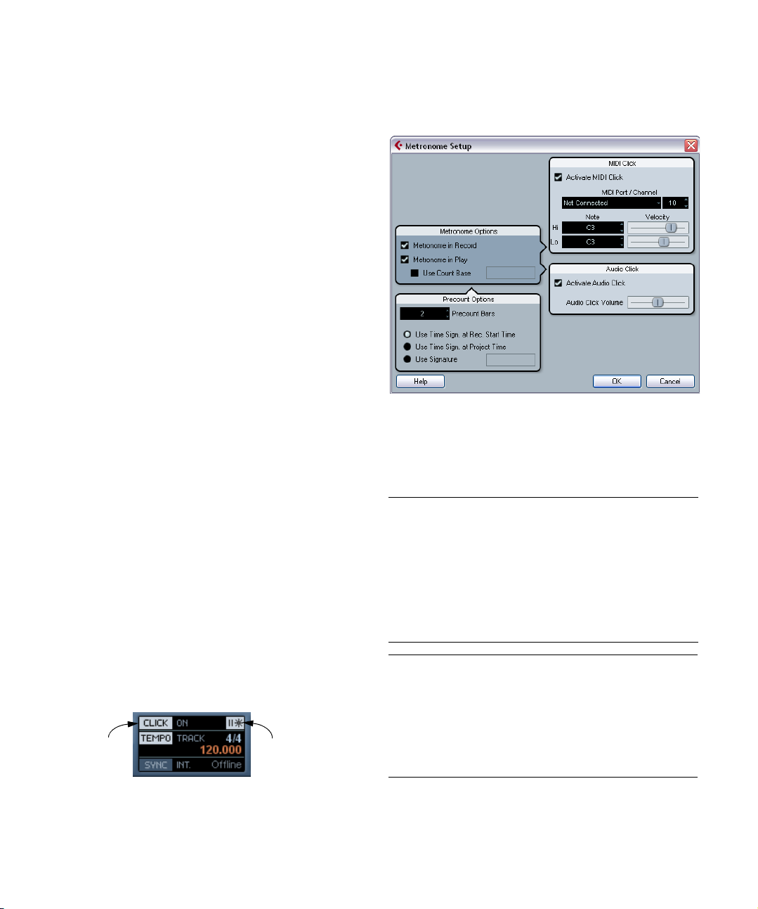
An example:
1. Set the locators to where you want to start and end recording.
2. Activate Punch in and Punch out on the Transport
panel.
3. Activate the option “Stop after Automatic Punch Out”
in the Preferences (Transport page).
4. Set suitable preroll and postroll times by clicking in the
corresponding fields on the Transport panel and typing in
time values.
5. Activate preroll and postroll by clicking the buttons
next to the preroll and postroll times so that they light up.
6. Activate recording.
The project cursor “rolls back” by the time specified in the preroll field
and playback starts. When the cursor reaches the left locator, recording
is automatically activated. When the cursor reaches the right locator, recording is deactivated, but playback continues for the time set in the
postroll field before stopping.
Metronome settings
You make settings for the metronome in the Metronome
Setup dialog, opened from the Transport menu.
Using the metronome
The metronome can output a click that can be used as a
timing reference. The two parameters that govern the timing of the metronome are tempo and time signature, and
these are edited in the Tempo Track window (see “Editing
the tempo curve” on page 267).
You can use the metronome for a click during recording
and/or playback or for a precount (count-in) that will be
heard when you start recording from Stop mode. Click
and precount are activated separately:
• To activate the metronome, click the Click button on the
Transport panel.
You can also activate the “Metronome On” option on the Transport menu
or use the corresponding key command (by default [C]).
• To activate the precount, click the Precount button on
the Transport panel.
You can also activate the “Precount On” option on the Transport menu
or set up a key command for this.
Click on/off Precount on/off
The metronome can use either an audio click played back
via the audio hardware, send MIDI data to a connected
device which will play back the click or do both.
The following metronome settings can be made in the
dialog:
Metronome
Options
Metronome in
Record / Play
Use
Count Base
Precount
Options
Precount Bars Sets the number of bars the metronome will count in be-
Use Time
Signature at
Record Start
Time
Description
Allows you to specify whether the metronome should be
heard during playback, recording or both (when Click is
activated on the Transport panel).
If this option is activated, a field appears to the right
where you specify the “rhythm” of the metronome. Normally, the metronome plays one click per beat, but setting this to e.g. “1/8” gives you eighth notes – two clicks
per beat. It’s also possible to create unusual metronome
rhythms such as triplets etc.
Description
fore it starts recording if precount is activated on the
Transport panel.
When this is activated, the precount will automatically
use the time signature and tempo set at the position
where you start recording.
60
Recording
Page 61
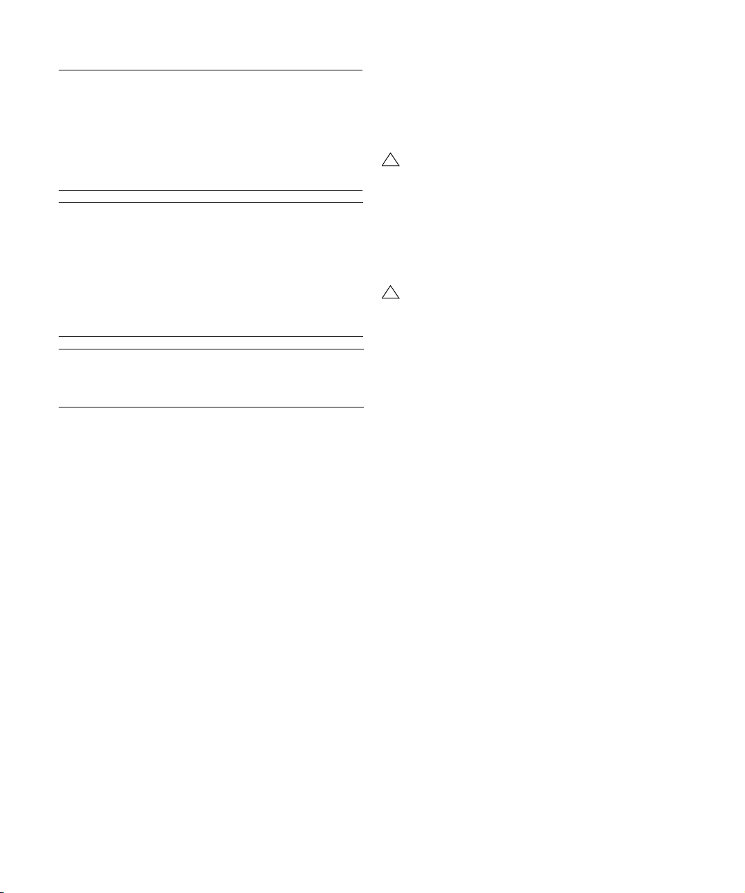
Precount
Options
Use Time
Signature at
Project Time
Use
Signature…
MIDI Click Description
Activate MIDI
Click
MIDI Port/
Channel
Hi Note/
Velocity
Lo Note/
Velocity
Audio Click Description
Activate
Audio Click
Description
When this is activated, the precount will be in the time
signature set in the Tempo track. Furthermore, any
tempo changes in the Tempo track during the precount
will be applied.
This lets you set a time signature for the precount. In this
mode, tempo changes in the Tempo track won’t affect
the precount.
Selects whether or not the metronome will sound via
MIDI.
This is where you select a MIDI output and channel for
the metronome click.
Sets the MIDI note number and velocity value for the
“high note” (the first beat in a bar).
Sets the MIDI note number and velocity for the “low
notes” (the other beats).
Selects whether or not the metronome will sound via the
audio hardware. You can set the level of the click with the
slider.
Recovery of audio recordings after system failure
When you experience a computer crash during a recording, simply relaunch the system and check the project
record folder (by default this is the Audio subfolder inside
the project folder). It should contain the audio file you
were recording at the time of the crash.
!
Please note: This feature does not constitute an
“overall” guarantee by Steinberg. While the program
itself was improved in such a way that audio recordings can be recovered after a system failure, it is always possible that a computer crash, power cut, etc.
might have damaged another component of the
computer, making it impossible to save or recover
any of the data.
!
Warning: Please do not try to actively bring about
this kind of situation to test this feature. Although the
internal program processes have been improved to
cope with such situations, Steinberg cannot guarantee that other parts of the computer are not damaged
as a consequence.
Normally, when a computer crashes, all changes made to
your current project since you last saved it will be lost. Usually, there is no quick and easy way to recover your work.
With Cubase Essential, when your system crashes while
you are recording (because of a power cut or other mishap), you will find that your recording is still available, from
the moment when you started recording to the time when
your computer crashed.
Recording
61
Page 62

6
Fades, crossfades and envelopes
Page 63
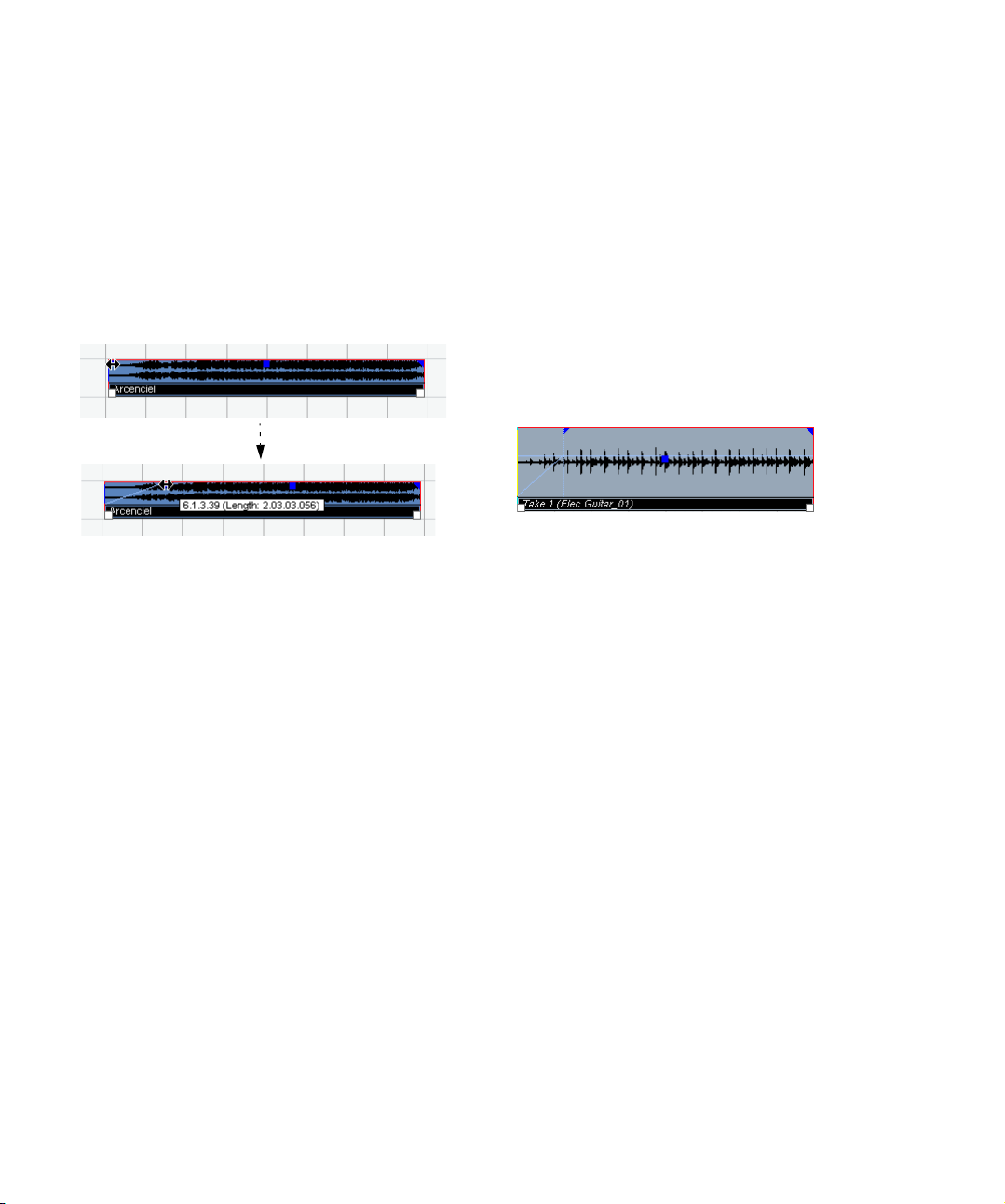
Creating fades
There are two main types of fade-ins and fade-outs in audio events in Cubase Essential: fades created by using
the fade handles (see below) and fades created by processing (see “Fades created by processing” on page 64).
Fades created by using the fade handles
Selected audio events have blue handles in the upper left
and right corners. These can be dragged to create a fadein or fade-out respectively.
Creating a fade-in. The fade is automatically reflected in the shape of
the event’s waveform, giving you a visual feedback of the result when
you drag the fade handle.
Fades created with the handles are not applied to the audio clip as such but calculated in real time during playback. This means that several events referring to the same
audio clip can have different fade curves. It also means
that having a huge number of fades may demand a lot of
processor power.
• If you select multiple events and drag the fade handles
on one of them, the same fade will be applied to all selected events.
• A fade can be edited in the Fade dialog, as described
on the following pages.
You open the dialog by double-clicking in the area above the fade curve,
or by selecting the event and selecting “Open Fade Editor(s)” from the
Audio menu (note that this will open two dialogs if the event has both
fade-in and fade-out curves).
If you adjust the shape of the fade curve in the Fade dialog, this shape
will be maintained when you later adjust the length of a fade.
• You can make the fade longer or shorter at any time, by
dragging the handle.
You can actually do this even without selecting the event first, i.e. without
visible handles. Just move the mouse pointer along the fade curve until
the cursor turns into a bidirectional arrow, then click and drag.
• If the option “Fade Handles always on Top” is activated
in the Preferences dialog (Event Display-Audio page), the
fade handles stay at the top of the event, and vertical help
lines indicate the exact end or start points of fades.
This is useful in situations where you want the event volume to be very
low, as this option allows you to still see the fade handles.
• If the option “Show Event Volume Curves Always” is ac-
tivated in the Preferences (Event Display–Audio page),
the fade curves will be shown in all events, regardless of
whether they are selected or not.
If the option is deactivated, the fade curves are shown in selected events
only.
• If the option “Thick Fade Lines” is activated in the Pref-
erences dialog (Event Display-Audio page), the fade lines
and volume curve are thicker, increasing their visibility.
Fade handles on top of the event and thicker fade and volume lines allow you to edit and view fades even in situations where event volume is
very low.
• When the option “Use Mouse Wheel for Event volume
and Fades” is activated in the Preferences dialog (Editing–Audio page), you can use the mouse wheel to move
the volume curve up or down. When you hold down [Shift]
while moving the mouse wheel, this will change the fade
curves. This is useful in situations where the fade handles
are not visible (e.g. because of a very high zoom factor).
When you position the mouse pointer somewhere in the left half of the
event, the fade in end point is moved. When the mouse pointer is in the
right half of the event, the fade out start point will move.
Ö You can set up key commands for changing the event
volume curve and any fade curves, if you don’t want to use
the mouse for this.
You will find these commands in the Key Commands dialog, in the Audio
category. See “Key commands” on page 321.
63
Fades, crossfades and envelopes
Page 64

Creating and adjusting fades with the Range Selection
tool
“Handle-type” fades can also be created and adjusted
with the Range Selection tool, in the following way:
1. Select a section of the audio event with the Range Selection tool.
The result depends on your selection, in the following way:
• If you select a range from the beginning of the event, a fade-in
will be created within the range.
• If you select a range that reaches the end of an event, a fadeout will be created in the range.
• If you select a range encompassing a middle section of the
event, but not reaching neither the start nor the end, both a
fade-in and a fade-out will be created outside of the selected
range. In other words, the fade-in will cover the area from the
beginning of the event to the beginning of the selected range,
and the fade-out will cover the area from the end of the selected range to the end of the event.
2. Pull down the Audio menu and select “Adjust Fades to
Range”.
The fade areas are adjusted according to the selection range.
!
You can select multiple audio events on separate
tracks with the Range Selection tool, and apply the
fade to all of them simultaneously.
About the volume handle
A selected audio event also has a blue handle in the top
middle. This is the volume handle, and it provides a quick
way of changing the volume of an event, directly in the
Project window. It is linked directly to the volume setting
on the info line, that is, dragging the volume handle also
changes the value on the info line.
The volume change is displayed
numerically on the info line.
The event waveform reflects the volume change.
Drag the Volume handle up or
down to change the volume
of the event.
Removing fades
To remove the fades for an event, select the event and select “Remove Fades” from the Audio menu.
You can also use the Range Selection tool to remove
fades and crossfades within the selected range:
1. Drag the Range Selection tool in the Project window,
so that the selection encloses all of the fades and crossfades you wish to remove.
2. Select “Remove Fades” from the Audio menu.
Fades created by processing
If you have selected an audio event or a section of an audio event (using the Range Selection tool), you can apply
a fade-in or fade-out to the selection by using the “Fade
In” or “Fade Out” functions on the Process submenu on
the Audio menu. These functions open the corresponding
Fade dialog, allowing you to specify a fade curve.
!
Note that the length of the fade area is determined
by your selection. In other words, you specify the
length of the fade before you enter the Fade dialog.
!
Also note that you can select multiple events and apply the same processing to all of them simultaneously.
Fades created this way are applied to the audio clip rather
than to the event. Please note the following:
• If you later create new events that refer to the same clip, these
will have the same fades.
• You can remove or modify the fades at any time using the Offline Process History (see “The Offline Process History dialog”
on page 147).
64
Fades, crossfades and envelopes
Page 65

If other events refer to the same audio clip, you will be
asked whether you want the processing to be applied to
these events or not.
• Continue will apply the processing to all events that refer to
the audio clip.
• New Version will create a separate, new version of the audio
clip for the selected event.
• You can also choose to put a checkmark in the “Do not show
this message again” box. Regardless of whether you then
choose “Continue” or “New Version”, any further processing
will conform to the option you select.
!
You can change this setting at any time in the Preferences (Editing–Audio page), under “On Processing
Shared Clips”.
The Fade dialogs
The Fade dialogs appear when you edit an existing fade or
use the “Fade In”/“Fade Out” functions on the Process
submenu on the Audio menu. The picture below shows
the Fade In dialog; the Fade Out dialog has identical settings and features.
Fade display
Shows the shape of the fade curve. The resulting waveform shape is shown in dark gray, with the current waveform shape in light gray.
You can click on the curve to add points, and click and
drag existing points to change the shape. To remove a
point from the curve, drag it outside the display.
Curve shape buttons
These buttons give you quick access to some common
curve shapes.
Restore button
The Restore button (to the right above the fade display) is
only available when editing fades made by dragging the
fade handles. Click this to cancel any changes you have
made since opening the dialog.
As Default button
The “As Default” button is only available when editing
fades made by dragging the fade handles. Click this to
store the current settings as the default fade. This shape
will be used whenever you create new fades.
• If you open the Fade dialog(s) with several events se-
lected, you can adjust the fade curves for all these events
at the same time.
This is useful if you want to apply the same type of fade-in to more than
one event, etc.
Curve Kind
These determine whether the fade curve should consist of
spline curve segments (left button), damped spline segments (middle button) or linear segments (right button).
Fades, crossfades and envelopes
Fade Length Value
The Fade Length Value can be used to enter fade lengths
numerically. The format of values displayed here are determined by the Primary Time Display in the Transport Panel.
When you activate the “Apply Length” option, the value entered in the Fade Length value field will be used when clicking “Apply” or “OK”. This setting is deactivated by default.
When you set the current Fade as the Default fade, the
length value is included as part of the default settings.
Presets
If you have set up a fade in or fade out curve that you may
want to apply to other events or clips, you can store it as a
preset by clicking the Store button.
• To apply a stored preset, select it from the pop-up
menu.
65
Page 66

• To rename the selected preset, double-click on the
name and type a new one.
• To remove a stored preset, select it from the pop-up
menu and click Remove.
!
Stored fade in presets will only appear in the Fade In
dialog, and fade out presets will only appear in the
Fade Out dialog.
Preview, Apply and Process
The buttons in the bottom row are different depending on
whether you are editing a fade made with the fade handles
or applying a fade using processing:
The Edit Fade dialog.
The Process Fade dialog.
The Edit Fade dialogs have the following buttons:
Button Function
OK Applies the set fade curve to the event, and closes the dialog.
Cancel Closes the dialog.
Apply Applies the set fade curve to the event, without closing the
dialog.
The Process Fade dialogs have the following buttons:
Button Function
Preview Plays back the fade area. Playback will repeat until you click
Process Applies the set fade curve to the clip, and closes the dialog.
Cancel Closes the dialog without applying any fade.
the button again (the button is labeled “Stop” during playback).
Creating crossfades
Overlapping audio material on the same track can be
crossfaded, for smooth transitions or special effects. You
create a crossfade by selecting two consecutive audio
events and selecting the Crossfade command on the Audio menu (or by using the corresponding key command,
by default [X]). The result depends on whether the two
events overlap or not:
• If the events overlap, a crossfade is created in the overlapping area.
The crossfade will be of the default shape – initially a linear, symmetric
crossfade, but you can change this as described below.
Overlapping section
• If the events don’t overlap but are directly consecutive
(lined up end-to-start, with no gap) it’s still possible to
crossfade them – provided that their respective audio
clips overlap! In this case, the two events are resized so
that they overlap, and a crossfade of the default length
and shape is applied.
The default crossfade length and shape are set in the Crossfade dialog
(see “Default buttons” on page 68).
66
Fades, crossfades and envelopes
Page 67

An example:
Audio events.
Audio clips.
The events in themselves do not overlap, but their clips do. Therefore,
the events can be resized so that they overlap, which is required for a
crossfade to be created.
When you select the Crossfade function, the two events are resized so that
they overlap, and a default crossfade is created in the overlapping section.
• If the events don’t overlap, and cannot be resized
enough to overlap, a crossfade cannot be created.
• Once you have created a crossfade, you can edit it by
selecting one or both crossfaded events, and selecting
“Crossfade” from the Audio menu again (or by doubleclicking in the crossfade zone).
This opens the Crossfade dialog, see below.
Removing crossfades
To remove a crossfade, select the events and select “Remove Fades” from the Audio menu, or use the Range Selection tool:
1. Drag the Range Selection tool in the Project window,
so that the selection encloses all of the fades and crossfades you wish to remove.
2. Select “Remove Fades” from the Audio menu.
• You can also remove a crossfade by clicking and drag-
ging it outside the track.
The Crossfade dialog
The Crossfade dialog contains separate, but identical,
sections for the fade-in and fade-out curve settings in the
crossfade on the left, and common settings on the right.
Fade Displays
Shows the shape of the fade-out and fade-in curve, respectively. You can click on the curve to add points, and
click and drag existing points to change the shape. To remove a point from the curve, drag it outside the display.
Curve kind buttons
These buttons determine whether the corresponding fade
curve should consist of spline curve segments (left button), damped spline segments (middle button) or linear
segments (right button).
Curve shape buttons
These buttons give you quick access to some common
curve shapes.
Equal Power and Gain
• If you activate the “Equal Gain” checkbox, the fade
curves are adjusted so that the summed fade-in and fadeout amplitudes will be the same all along the crossfade
region. This is often suitable for short crossfades.
• If you activate the “Equal Power” checkbox, the fade
curves are adjusted, so that the energy (power) of the
crossfade will be constant all along the crossfade region.
!
Equal Power curves have only one editable curve
point. You cannot use the Curve kind buttons or the
presets when this mode is selected.
67
Fades, crossfades and envelopes
Page 68

Play buttons
• The “Play Fade Out” and “Play Fade In” buttons allow
you to audition the fade-out or fade-in part only, without
the crossfade.
• The “Play Crossfade” button plays back the whole
crossfade.
You can also use the Transport play controls to play back
the crossfaded audio events. However, that method will
play back all unmuted audio events on other tracks as well.
Pre-roll and Post-roll
When auditioning with the Play buttons, you can choose
to activate pre-roll and/or post-roll. Pre-roll lets you start
playback before the fade area, and post-roll lets you stop
playback after the fade area. This can be useful for auditioning the fade in a context.
• To specify how long the pre- and post-rolls should be,
click in the time fields and enter the desired time (in seconds and milliseconds).
• To activate pre- and post-roll, click the respective but-
ton. To deactivate, click the button again.
Length settings
You can adjust the length of the crossfade area numerically in the “Length” field. If possible, the length change
will be applied equally to “both sides” of the crossfade
(i.e. Cubase Essential tries to “center” the crossfade).
!
To be able to resize a crossfade this way, it must be
possible to resize the corresponding event. For example, if the left crossfaded event already plays its
audio clip to the end, its endpoint cannot be moved
any further to the right.
Default buttons
• Clicking the “As Default” button stores all of the current
settings as the default crossfade. These settings will then
be used whenever you create new crossfades.
• The Crossfade Length setting is included in the Default
settings. However, it is only applied if the events to be
crossfaded don’t overlap – otherwise the crossfade will be
in the overlap area (see “Creating crossfades” on page 66).
• Clicking the “Recall Default” button copies the curves
and settings of the Default crossfade to the Crossfade
dialog.
Auto Fades and Crossfades
Cubase Essential features an Auto Fade function that can
be set both globally, i.e. for the entire project, and separately for each audio track. The idea behind the Auto Fade
function is to create smoother transitions between events
by applying short (1–500 ms) fade-ins and fade-outs.
!
As mentioned earlier, fades are calculated in real
time during playback. This means that the larger the
number of audio tracks with Auto Fades activated in
a project, the higher the demands on the processor.
!
Note that auto fades are not indicated by the fade
lines!
Making global Auto Fade settings
1. To make Auto Fades settings globally for the project,
select “Auto Fades Settings...” from the Project menu.
This opens the Auto Fades dialog for the project.
Presets
If you have set up a crossfade shape that you may want to
apply to other events, you can store it as a preset by clicking the Store button.
• To apply a stored preset, select it from the pop-up menu.
• To rename the selected preset, double-click on the
name and type in a new one.
• To remove a stored preset, select it from the pop-up
menu and click Remove.
Fades, crossfades and envelopes
68
Page 69

2. Use the checkboxes in the upper right corner to acti-
vate or deactivate Auto Fade In, Auto Fade Out and Auto
Crossfades, respectively.
3. Use the Length value field to specify the length of the
Auto Fade or Crossfade (1-500ms).
4. To adjust the shapes of Auto Fade In and Auto Fade
Out, select the “Fades” tab and make settings as in the
regular Fade dialogs.
5. To adjust the shape of the Auto Crossfade, select the
“Crossfades” tab and make settings as in the regular
Crossfade dialog.
6. If you want to use the settings you have made in future
projects, click the “As Default” button.
The next time you create a new project, it will use these settings by default.
7. Click OK to close the dialog.
Making Auto Fade settings for a separate track
By default, all audio tracks will use the settings you have
made in the project’s Auto Fades dialog. However, since
Auto Fades use computing power, a better approach may
be to turn Auto Fades off globally and activate them for individual tracks, as needed:
1. Right-click the track in the Track list and select “Auto
Fades Settings...” from the context menu (or select the
track and click the “Auto Fades Settings” button in the Inspector).
The Auto Fades dialog for the track opens. This is identical to the project’s
Auto Fades dialog, with the addition of a “Use Project Settings” option.
2. Deactivate the “Use Project Settings” option.
Now, any settings you make will be applied to the track only.
3. Set up the Auto Fades as desired and close the dialog.
Reverting to project settings
If you want a track to use the global Auto Fade settings,
open the Auto Fades dialog for the track and activate the
“Use Project Settings” checkbox.
Fades, crossfades and envelopes
69
Page 70

7
The Arranger track
Page 71

Introduction
The Arranger track allows you to work with sections of
your project in a non-linear fashion, to simplify arranging to
the maximum extent. Instead of moving, copying and pasting events in the Project window event display to create a
linear project, you can define how different sections are to
be played back, like a playlist.
For this, you can define arranger events, order them in a list,
and add repeats as desired. This offers a different and more
pattern-oriented way of working, which complements the
usual linear editing methods in the Project window.
You can create several Arranger chains, making it possible to store different versions of a song within the project
without sacrificing the original version. When you have
created an Arranger chain that you like, you have the option of “flattening” the list, which creates a normal linear
project based on the Arranger chain. You can chose to
keep the Arranger track or to remove it.
You can also use the Arranger track for live performances
on the stage, in clubs or at parties.
Setting up the Arranger track
Let’s say you have prepared a number of audio files that
form the base of a typical pop song, with introduction,
verse, chorus and bridge. Now you want to arrange these
files.
The first step is to create an Arranger track. On the Arranger track, you define specific sections of the project by
creating arranger events. These can be of any length, may
overlap and are not bound to the start or end of existing
events and parts. Proceed as follows:
1. Open the project for which you want to create arranger
events.
2. Open the Project menu and select “Arranger” from the
Add Track submenu (or right-click in the Track list and select Add Arranger track).
An Arranger track is added. There can be only one Arranger track in a
project, but you can set up more than one Arranger chain for this track,
see “Managing Arranger chains” on page 74.
3. On the Project window toolbar, make sure that Snap
is activated, and that the Grid resolution is set to a mode
that allows your arranger events to snap to appropriate
positions in the project.
Snap to events is activated, i.e. when drawing in the Project window,
new events will snap to existing events.
4. On the Arranger track, use the Pencil tool to draw an
event of the desired length.
An Arranger event is added, called “A” by default. Any following events
will be named in alphabetical order.
• You can rename an Arranger event by selecting it and
changing its name in the Project window info line or by
holding down [Alt]/[Option], double-clicking on the name
in the Arranger chain (see below) and entering a new
name.
You may want to name your arranger events according to the structure of
your project, e.g. Verse, Chorus etc.
5. Create as many events as you need for your project.
In this example, arranger events have been created that correspond to a
classic pop song structure. Note how there is no real time line in the
project: the music sequence is determined by the arranger events.
Events can be moved, resized and deleted using the standard techniques. Please note:
• If you want to change the length of a event, select the
Arrow tool and click and drag the bottom corners of the
event in the desired direction.
• If you copy an Arranger event (by [Alt]/[Option]-dragging or by using copy/paste), a new event will be created
with the same name as the original.
However, this new event will be totally independent from the original event.
• Double-clicking on an arranger event adds it to the current Arranger chain.
71
The Arranger track
Page 72

Working with arranger events
You now have a number of arranger events that form the
basic building blocks for your arrangement. The next step
is to arrange these events using the functions of the Arranger Editor.
Creating an Arranger chain
You can set up an Arranger chain in the Arranger Editor or
in the Inspector for the Arranger track. The Arranger Editor
is opened by clicking the “e” button in the Inspector or in
the Arranger track.
Click in the Inspector…
…or the Track list…
…to open the Arranger Editor.
To the right in the Arranger Editor, the available arranger
events are listed, in the order they appear on the time line.
To the left you find the actual Arranger chain, which shows
in which order the events will be played back, from top to
bottom, and how many times they should be repeated.
Initially the Arranger chain will be empty – you set up the
Arranger chain by adding events from the right list to the
Arranger chain. There are several ways to add events to
the Arranger chain.
• Double-clicking on the name of an event in the window
section on the right (or in the project window).
When an event is selected in the Arranger chain on the left will add the
event above the selected event. When no events are selected in the Arranger chain on the left will add the event to the end of the list.
• By selecting one or more events in the right list, rightclicking and selecting “Append Selected In Arranger
Chain”.
This will add the selected events at the end of the list.
• By dragging and dropping arranger events from the
right list to the left list.
A blue insertion line shows you where the dragged event will end up in the
list.
Here, the Verse event is dragged into the Arranger chain and placed after the first chorus.
• By dragging arranger events from the Project window
and dropping them in the Arranger chain.
If you followed our example, you should now have arranger
events arranged in a very basic pop song pattern. However, we have used audio files that are only a few bars
long – to turn our pattern into a “song” (or at least into a
basic sketch of the song structure), these files must be
looped. This is where the Repeats function comes in.
If you want an event to repeat several times, proceed as
follows:
• Click in the Repeats field for an event, type in the desired number of repeats and press [Enter].
When playing back the Arranger chain, the Counter column indicates
which repeat of this event is currently playing.
72
The Arranger track
Page 73
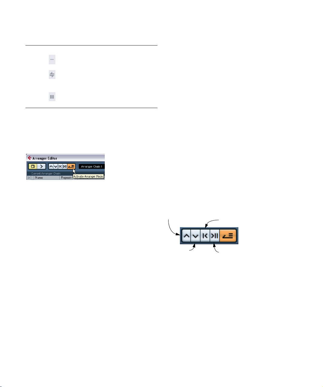
• Click in the Mode field for an event and select the de-
sired repeat mode.
Option Button Description
Normal In this mode, your Arranger chain will be played
Repeat
forever
Pause after
Repeats
back normally, just as you set it up.
In this mode, the current Arranger event will be repeated in a loop until you either click on another
event in the Arranger Editor or press play once
again.
In this mode, the playback of the Arranger chain
will be stopped after having played back all repeats of the current Arranger event.
When you now play back the Arranger chain, you will hear
the complete arrangement. Proceed as follows:
1. Make sure that Arranger mode is activated.
When Arranger mode is activated, the project will be played back using
the Arranger settings.
The Arranger mode button must be activated.
2. Position the Arranger Editor window so that you can
see the Arranger track in the Project window, and click in
the arrow column for the event at the top of the list so that
the arrow becomes blue.
You should see the project cursor jump to the beginning of the first event
specified in the Arranger chain.
3. Activate playback, either from the Arranger Editor or
on the Transport panel.
The events are played back in the specified order.
Editing the Arranger chain
In the Arranger chain to the left, you can do the following:
• Select multiple events by [Ctrl]/[Command]-clicking or
[Shift]-clicking as usual.
• Drag events to move them in the list.
• Drag events while holding [Alt]/[Option] to create cop-
ies of the selected items.
The insert location for both move and copy operations is indicated by a
blue or red line in the list. A blue line indicates that the move or copy is
possible; a red line indicates that if the current position were to be used,
a move or copy is not allowed.
• Use the Repeats column to specify how many times
each event should be repeated.
• Click the arrow to the left of an event in the Arranger
chain to move the playback position to the start of that
event.
• To remove an event from the list, right-click on it and select “Remove Touched” from the pop-up menu that appears. To remove several events, select them, right-click
and select “Remove Selected”.
Navigating
To navigate between arranger events, you use the Arranger transport buttons:
Previous chain step
Next chain step
First repeat of current chain step
Last repeat of current chain step
These controls are available in the Arranger Editor, the
Project window toolbar, and the Transport panel.
In the Arranger Editor, the event that is currently played
back is indicated by an arrow in the leftmost column, and
the indicators in the Counter column.
73
The Arranger track
Page 74
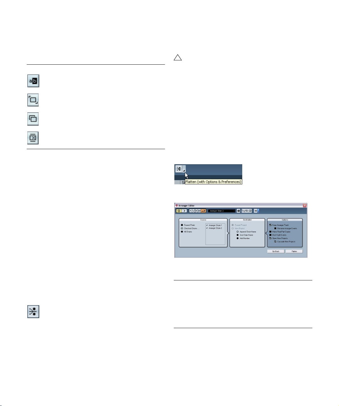
Managing Arranger chains
You can create several Arranger chains. This way, you can
create alternative versions for playback. In the Arranger
Editor, the toolbar buttons on the right are used for this:
Button Description
Click this to rename the current Arranger chain.
Creates a new, empty Arranger chain.
Creates a duplicate of the current Arranger chain, containing
the same events.
Removes the currently selected Arranger chain. Only available if you have created more than one Arranger chain.
• In the Inspector, these functions are accessed from the
Arranger pop-up menu (opened by clicking on the Arranger name field).
The Arranger chains you create will be listed on the Name
pop-up menu, found in the Arranger Editor to the left of
the buttons, at the top of the Arranger track Inspector, and
in the Track list. Please note that to be able to select another Arranger chain from the pop-up menu, Arranger
mode must be activated.
2. Activate Playback.
The project will now play back exactly as in Arranger mode, but you can
view it and work with it as usual.
!
Flattening the Arranger chain may remove events
and parts from the project. Only use the Flatten function when you know you don’t want to edit the Arranger track/chain any more. If in doubt, save a copy
of the project before flattening the Arranger chain.
Flattening options
Sometimes it might be useful to keep the original Arranger
events even after flattening the Arranger track. By using flattening options you can define which chain should be flattened (Source section), where it should be stored and how
it should be named (Destination section) together with
other options (Options section).
1. Click the Flattening options button.
2. In the window that appears, select the desired options.
Flattening the Arranger chain
When you have found an Arranger chain that suits your purposes, you can “flatten” it, i.e. convert the list into a linear
project. Proceed as follows:
1. Click the Flatten button (or select Flatten Chain from
the pop-up menu in the Inspector for the Arranger track).
The events and parts in the project are reordered, repeated, resized,
moved and/or deleted (if these are not within the boundaries of any used
Arranger event), so that they correspond exactly to the Arranger chain.
The Flatten button
The Arranger track
In the Source section you can specify, which Arranger
chain should be flattened. The available options are:
Option Description
Current Chain If you activate this option, only the current chain will be
flattened.
Checked Chains… If you activate this option, you can select the arranger
chains you want to flatten in the list to the left.
All Chains If you activate this option, all arranger chains of the
current project will be flattened.
74
Page 75

The Destination section allows you to choose where the
result of the flattening should be saved. The available options are:
Option Description
Current Project This option is only available, if you have selected “Current
New Project If you activate this option, you can flatten one or several
Chain” as Source. If you activate this option, the result of
the flattening of the current chain will be saved in the current project.
chains in a new project. In this case it might be useful to
use naming options. If you activate “Append Chain
Name”, the Chain Name(s) will be appended in brackets
to the project name. If you activate “Use Chain Name”,
the new project(s) will have the name of the current Arranger chain(s). If you activate “Add Number”, the new
project(s) will be named like the old ones and a number
will be appended in brackets.
In the Options section you can make further settings. The
available options are:
Option Description
Keep Arranger
Track
Make Real
Event Copies
Don’t Split
Events
Open New
Projects
If you activate this option, the Arranger Track will be kept
when flattening the Arranger chain. If you activate the option “Rename Arranger Events” a number will be appended to the events according to their use. If e.g. you
use Arranger event “A” two times, the first occurrence
will be renamed “A 1” and the second “A 2”.
Normally, you will get shared copies when flattening the
Arranger track. If you activate this option, real copies will
be created instead.
If the option is activated, MIDI notes that start before or
are longer than the Arranger event will not be included.
Only MIDI notes that begin and end inside the Arranger
event boundaries will be taken into account.
If you activate this option, a new project will be created
for every flattened Arranger chain. If you activate the option “Cascade New Projects” the opened projects will be
cascaded.
Live Mode
If you have set up an Arranger track and play it back, you
have also the possibility to influence the playback order
“live”. Note that the Arranger mode has to be activated to
be able to use the Live mode.
1. Add an Arranger track by selecting “Arranger” from the
Add Track submenu of the Project menu.
2. Create the desired Arranger events by drawing with
the Pencil tool on Arranger track.
3. Set up an Arranger chain in the Inspector for the Arranger track or in the Arranger Editor, activate the Arranger mode and play back your project.
Now you can use your Arranger events listed in the lower
section of the Arranger track Inspector to play back your
project in Live Mode:
4. Switch into Live mode by clicking on the little arrow in
the lower list of the Arranger track Inspector to the left of
the Arranger event you want to trigger.
The Arranger event will be looped endlessly, until you click on another Arranger event. This might be useful, if you want to loop e.g. a guitar solo with
a flexible length.
• You can stop Live mode by clicking the Stop button or
go back to “normal” playback in Arranger mode by clicking
on any arranger event in the upper list.
In the latter case, playback will be continued from the arranger event
where you clicked. The “Select grid” pop-up menu will always be taken
into account. When the grid is set to “1 Bar” and you click the STOP
button e.g., playback will be stopped after the next bar.
3. You can now flatten the Arranger track by clicking the
Flatten button.
If you realize that you want to do further arrangements, you can also click
the “Go Back” button and make your adjustments. Your Flattening settings will be kept.
4. Click the “Go Back” button to go back to the Arranger
Editor or close the window by clicking its Close button.
The Arranger track
75
Page 76
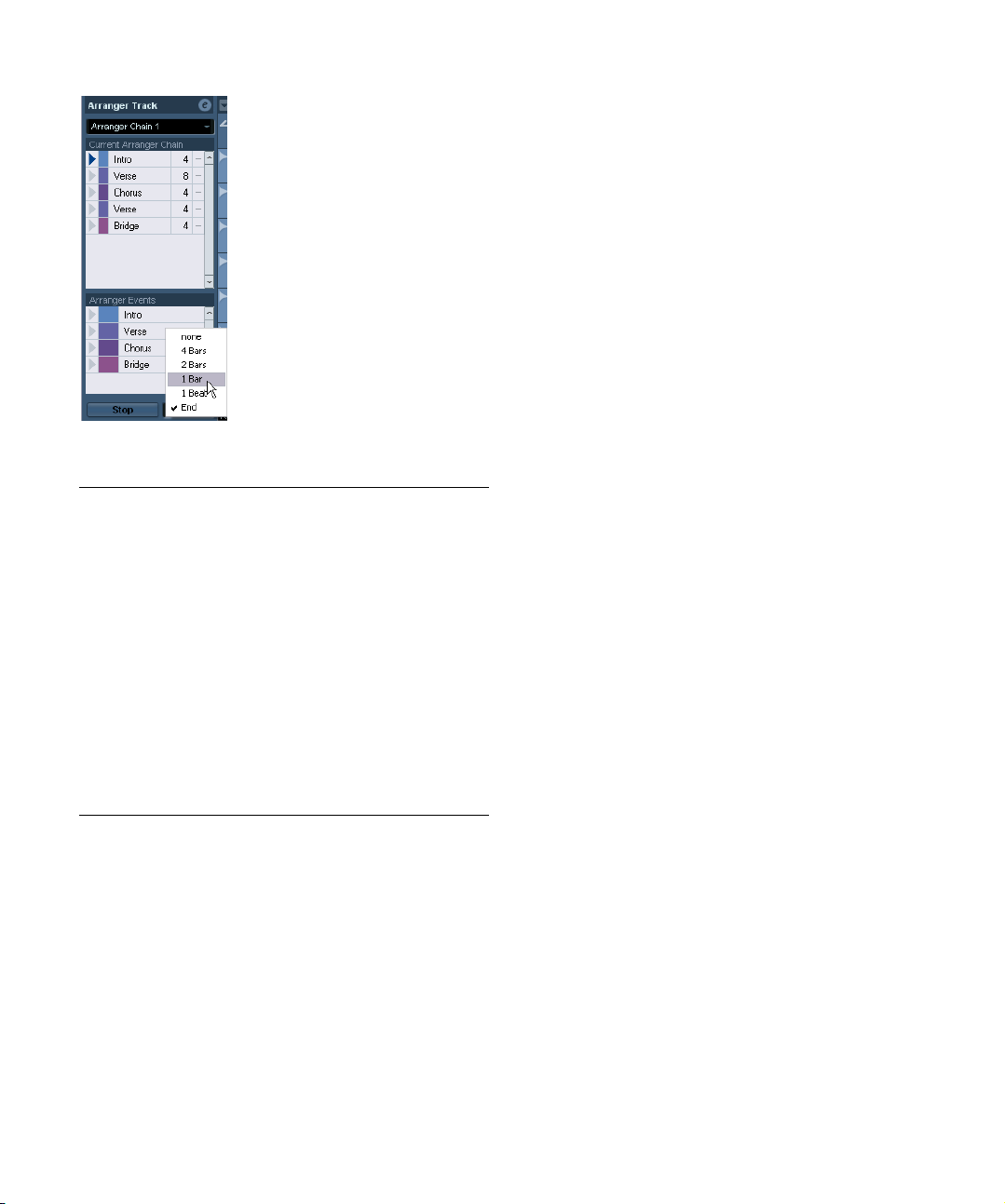
The active Arranger event will be played back as long as
defined before jumping to the next.
Option Description
Now Jumps to the next section immediately.
4 bars,
2 bars
1 bar Jumps to the next section at the next bar line.
1 beat Jumps to the next section at the next beat.
End Plays the current section to the end, then jumps to the next sec-
When one of these modes is selected, a grid of 4 or 2 bars (depending on the setting) will be placed on the active Arranger
event. Whenever the respective grid line is reached, playback
will jump to the next Arranger event. An example:
Let’s say you have an Arranger event which is 8 bars long and
the grid is set to 4 bars. When the cursor is anywhere within the
first 4 bars of the Arranger event when you hit the next Arranger
event, playback will jump to the next event when the end of the
fourth bar of the Arranger event is reached. When the cursor is
anywhere within the last 4 bars of the Arranger event, playback
will jump to the next event at the end of the event.
When an event is shorter than 4 (or 2) bars when this mode is
selected, playback will jump to the next section at the event end.
tion.
Arranging your music to video
The relative time of your Arranger track can be taken as a
reference instead of the project time. This is useful, if you
want to use the Arranger track to compose music for
video and fill e.g. a specific video section with music, by
repeating the corresponding number of Arranger events.
If you position your external sync master device to a position that does not match the Project Start time, Cubase
Essential will jump automatically to the right position in the
Arranger track and will start playback from there, i.e. the
correct relative position and not the absolute project time
will be found. The reference for the external timecode can
be MIDI or any other Timecode that can be interpreted/
read by Cubase Essential.
Ö If the Arranger mode is not activated or no Arranger
track exists, Cubase Essential will work as usual.
Below follows an example, that will help you understand
this functionality:
1. Set up a project with a MIDI track and three MIDI parts.
The first should start at position 00:00:00:00 and end at
position 00:01:00:00, the second should start at position
00:01:00:00 and end at position 00:02:00:00 and the
third should start at position 00:02:00:00 and end at position 00:03:00:00.
2. Activate the Sync button on the transport panel.
3. Add an Arranger track and create Arranger events that
match the MIDI parts.
4. Set up the Arranger chain “A-A-B-B-C-C”, activate
the Arranger mode and play back your project.
5. Start external Timecode at position 00:00:10:00
(within the range of “A”).
In your project, the position 00:00:10:00 will be located and you will hear
“A” playing. Nothing special!
Now, let’s see what happens if your external sync master
device starts at a position that does not match the Project
Start time:
6. Start at 00:01:10:00 (within the range of what originally was “B”).
In your project, the position 00:01:10:00 will be located and you will hear
“A” playing, because it plays twice in the Arranger track.
7. Start external Timecode at position 00:02:10:00
(within the range of what originally was “C”).
In your project, the position 00:02:10:00 will be located and you will hear
“B” playing, because it plays “later” in the Arranger track.
76
The Arranger track
Page 77

8
Folder tracks
Page 78
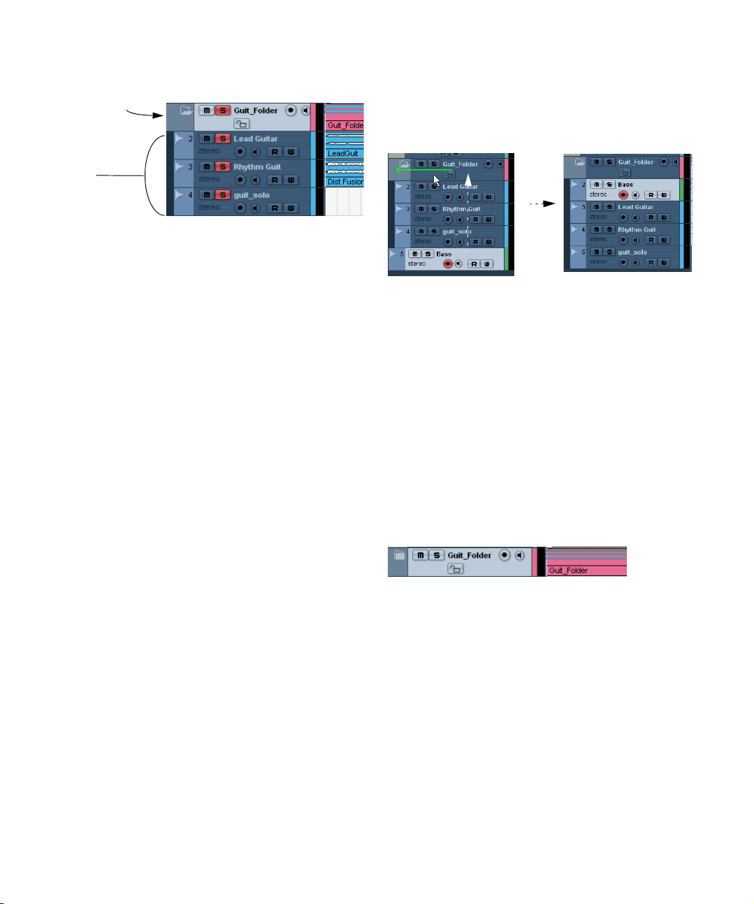
About folder tracks
A folder track
Tracks in the
folder
Just as the name implies, a folder track is a folder that contains other tracks. Moving tracks into a folder is a way to
structure and organize tracks in the Project window. For
example, grouping several tracks in a folder track makes it
possible for you to “hide” tracks (thus giving you more
working space on the screen). You can solo and mute
several tracks in a quicker and easier way and perform editing on several tracks as one entity. Folder tracks can
contain any type of track including other folder tracks.
2. Release the mouse button.
The track is now placed in the folder track, and all parts and events on
the track will be represented by a corresponding folder part (see “Wor-
king with folder parts” on page 79), which is a graphical representation
of all parts and events in the folder.
Since you can move any type of track into a folder track, it
is possible to create sub-folders by moving one folder
track into another. This is called “nesting”. For example,
you could have a folder containing all the vocals in a
project, and each vocal part could have a nested folder
containing all the takes for easier handling etc.
Handling folder tracks
Creating a folder track
Folder tracks are created just like any other track: Select
“Add Track” from the Project menu and select “Folder”
from the submenu that appears, or right-click in the Track
list and select “Add Folder Track” from the context menu.
Moving tracks into a folder
You can move any type of track into a folder by using drag
and drop:
1. In the Track list, click on a track that you want to move
into a folder and drag it onto a folder track.
A green arrow pointing to a folder appears when you drag the track onto
the folder track in the list.
Removing tracks from a folder
To remove a track from a folder, simply drag it out of the
folder and release it in the Track list.
Hiding/showing tracks in a folder
You can hide or show the tracks located in a folder by
clicking on the “Expand/Collapse Folder” button (the
folder icon). Hidden tracks are still played back as usual.
When a folder is “closed” this way, the folder part(s) still
give you a graphic representation of the parts and events
within the folder.
Muting and soloing folder tracks
One of the main advantages of using folder tracks is that
they provide you with a way to mute and solo several tracks
as one unit. Muting and soloing a folder track affects all
tracks in the folder. You can also solo or mute individual
tracks in the folder.
78
Folder tracks
Page 79
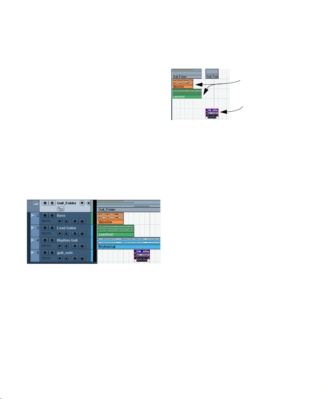
Muting a folder track
You can mute a folder track (and thereby mute all tracks
within it) the same way you mute other tracks by clicking in
the Mute (“M”) button in the Track list.
Soloing a folder track
You can solo a folder track (and thereby mute all tracks
outside the folder, except those already set to Solo) the
same way you solo other tracks, by selecting it and clicking the Solo button.
Soloing or muting tracks within a folder
This can be done by showing the tracks in the folder and
using the Mute and Solo buttons in the Track list as usual
for any tracks inside the folder.
Working with folder parts
A folder part is a graphic representation of events and
parts on the tracks in the folder. Folder parts indicate the
position and length of the events and parts, as well as on
which track they are (their vertical position). If part colors
are used, these are also shown in the folder part.
Folder parts are created automatically when there are parts
or events on the tracks within the folder. The following rules
apply:
• If there is a gap between parts/events on the tracks,
there will be two separate folder parts.
• Parts or events that overlap within the folder may be
represented by the same folder part or by two different
folder parts – depending on how much they overlap.
If a part/event overlaps by half its length or less, it will be placed in a new
folder part.
The first event overlaps the second event by more than half its
length, which means it is included
in the same folder part.
The third event does not overlap with any of the other events.
This means a new folder part is
created.
Handling and editing folder parts
Most of the editing you can do in the Project window applies to folder parts as well.
Any Project window editing you perform to a folder part
affects all the events and parts it contains (those elements
on the track within the folder that are represented by the
folder part). You can select several folder parts if you like
– this allows you to handle and edit them together. The
editing you can perform includes:
• Moving a folder part. This will move its contained events and
parts (possibly resulting in other folder parts, depending on
how the parts overlap).
• Using cut, copy and paste.
• Deleting a folder part. This will delete its contained events and
parts.
• Splitting a folder part with the Scissors tool (see the example
below).
• Gluing folder parts together with the Glue tube tool. This will
only work if the adjacent folder parts contain events or parts
on the same track.
• Resizing a folder part resizes the contained events and parts
according to the selected resizing method. This is set by clicking the Arrow tool icon on the toolbar and selecting “Normal
Sizing”, “Sizing Moves Contents” or “Sizing Applies Time
Stretch” from the pop-up menu – see “Resizing events” on
page 32. Note that if you select “Sizing Applies Time Stretch”,
any automation data is not taken into account.
• Muting a folder part. This will mute its contained events and
parts.
79
Folder tracks
Page 80
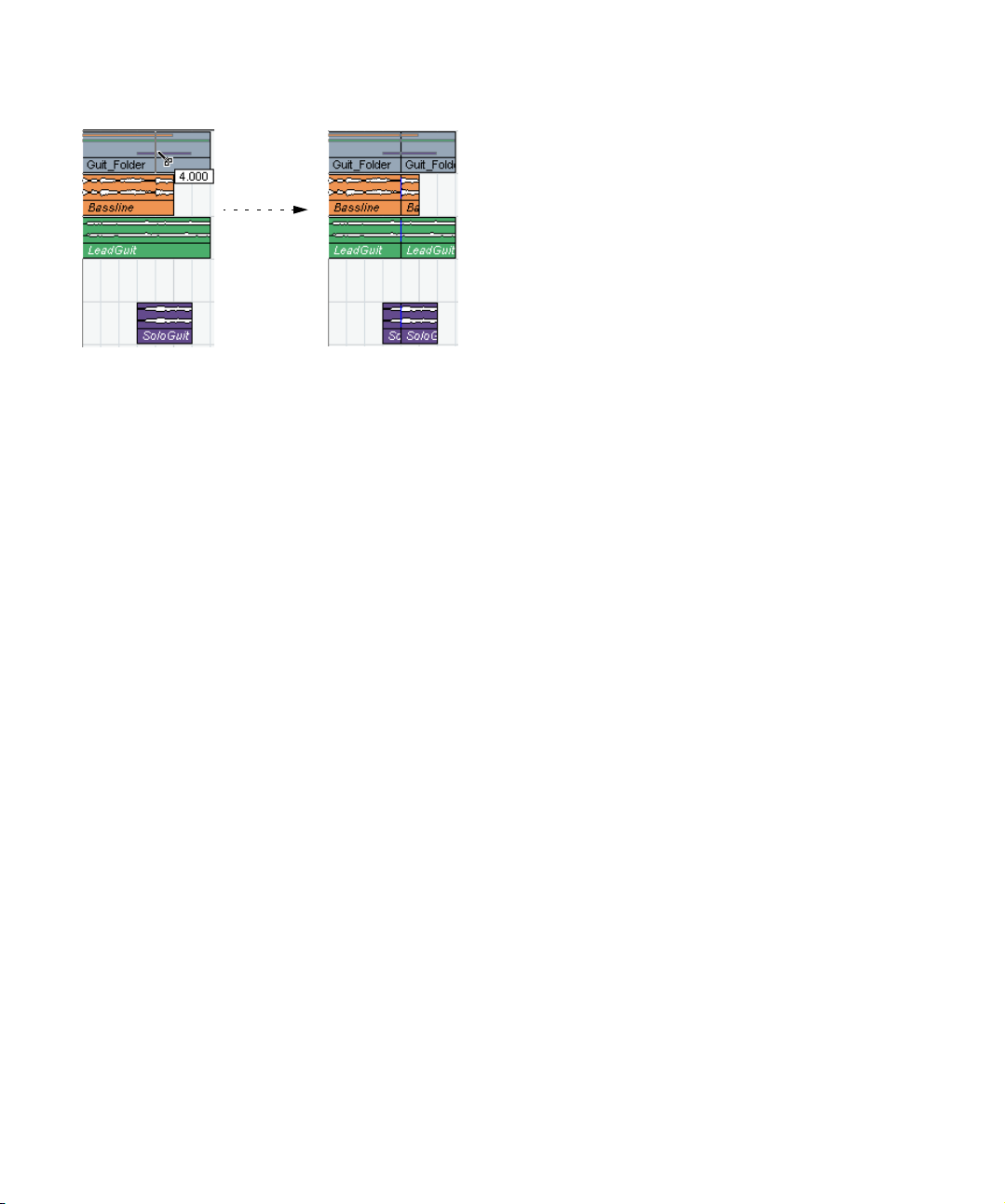
An example
Splitting the folder part
with the Scissors tool…
…will split all contained parts or
events present at that position.
Editing tracks within folder parts
Tracks inside a folder can be edited as one entity by performing the editing directly on the folder part containing
the tracks as explained above. You can also edit individual
tracks within the folder by showing the contained tracks,
selecting parts and opening editors as usual.
Double-clicking a folder part opens the editors for the corresponding track classes present in the folder. The following applies:
• All MIDI parts located on the tracks within the folder are
displayed as if they were on the same track, just like when
opening the Key Editor with several MIDI parts selected.
To be able to easily discern the different tracks in the editor, give each
track a different color in the Project window and use the “Part Colors”
option in the editor (see “Coloring notes and events” on page 231).
• If the folder contains tracks with audio events and/or audio parts, the Sample and/or Audio Part Editors are opened
with each audio event and audio part in a separate window.
80
Folder tracks
Page 81

9
Using markers
Page 82

About markers
Markers are used to locate certain positions quickly. If you
often find yourself jumping to a specific position within a
project, you should insert a marker at this position. There
are two types of markers:
• Cycle markers allow you to store the start and end positions of
a range.
• Standard markers store a specific position.
Markers can be created and edited in several ways:
• By using the Marker window (see below).
• By using the Marker track (see “Using the Marker track” on
page 83).
• By using key commands (see “Marker key commands” on
page 85).
Ö The left and right locators are handled separately –
see “The left and right locators” on page 44.
The Marker window
In the Marker window, you can perform most editing operations concerning markers. The markers are listed in the
Marker window in the order in which they occur in the
project. Most functions in the Marker window are also available in the Inspector when the Marker track is selected.
To open the Marker window, you can:
• Select “Markers” from the Project menu
• Click the “Show” button in the Marker section on the Transport panel
• Use the key command (by default [Ctrl]/[Command]-[M]).
The Marker window columns
The Marker window is divided into six columns which are
used for performing the following operations:
• The leftmost column is the Locate column.
Clicking in this column will move the project cursor to the corresponding
marker position. A blue arrow indicates the marker at the project cursor
position (or the closest marker before the project cursor).
• The ID column is used to edit marker ID numbers.
See “About marker ID numbers” on page 83.
• The Position column displays the markers’ time positions (or start positions for cycle markers).
The marker positions can be edited directly in this column.
• The End and Length columns display the end positions
and length of cycle markers – see “About cycle markers”
on page 83.
These values can also be edited directly in the respective column.
• The Description column lets you enter names or descriptions for markers.
Click on a column heading to sort the marker list by that
column. The Marker columns can also be reordered by
dragging and dropping the column headers.
Adding and removing markers in the Marker window
• You add position markers (in Stop mode, during playback or during recording) by clicking the Add button or by
pressing [Insert] (Windows only) on the computer keyboard. Markers are always added at the current project
cursor position.
• To add a cycle marker, select “Cycle Markers” from the
Show pop-up menu and click the Add button.
This adds a cycle marker between the left and right locator. You can also
draw cycle markers on the Marker track (see “Editing markers on the
Marker track” on page 84).
• To remove a marker, select it and click the Remove
button.
Ö Note that you can assign key commands to various
marker commands in the Key Commands dialog (see
“Marker key commands” on page 85).
82
Using markers
Page 83

Moving marker positions in the Marker window
The Move button in the Marker window can be used to
“reprogram” marker positions. Proceed as follows:
1. Set the project cursor to the position to which you
want to move (or re-program) a marker.
2. Select the marker that you want to change in the
Marker window.
Do not select the marker by clicking in the leftmost column, as this will
move the project cursor to this marker.
• If a cycle marker is selected, the Move operation affects
the cycle marker start position.
The length of the range is not affected.
3. Click the Move button.
You can also move markers by editing their position numerically in the Position column.
About marker ID numbers
Each time you add a marker, it is automatically and sequentially assigned an ID number, starting from ID 1. ID
numbers can be changed at any time – this allows you to
assign specific markers to key commands (see below).
IDs for cycle markers are shown in brackets and start from
[1]. These may also be changed.
Assigning markers to key commands
As explained above, marker ID numbers are assigned automatically and sequentially each time you add a marker.
The nine first markers (1 to 9) can be recalled by using key
commands – by default these are [Shift]-[1] to [9] on the
typewriter part of the keyboard.
Ö If you have more than nine markers, you cannot use
key commands to navigate to markers numbered 10 or
higher.
If you want to keep all current markers, but want to specify
which markers should be accessed via key commands,
the solution is to reassign the marker ID numbers. Proceed as follows:
1. First decide which of the current markers with an ID
between 1 and 9 you want to reassign to a new ID number,
and thus remove its key command assignment.
Memorize the ID number.
2. Enter this ID number in the ID column of the marker you
want to access with a key command and press [Enter].
The two marker ID numbers are switched, and the key command now
locates to the marker selected in this step.
3. Repeat as necessary for other markers.
• You can also simply remove a marker with an ID number
between 1 to 9 to free up a key – see “Adding and remo-
ving markers in the Marker window” on page 82.
• For more about marker key commands, see “Marker key
commands” on page 85.
Using the Marker track
Markers
Cycle marker
The Marker track is used for viewing and editing markers.
Markers shown on the Marker track are exactly the same
as shown in the Marker window, and any changes made
on the Marker track are reflected in the Marker window
and vice versa. Standard position markers in the Marker
track are shown as marker events: vertical lines with the
marker name (if assigned) and number beside it. If you select the Marker track, all markers are shown in the Inspector, much like in the Marker window.
About cycle markers
Cycle markers are shown on the Marker track as two
markers bridged by a horizontal line. Cycle markers are
ideal for storing sections of a project. By setting cycle
markers for sections of a song, for example “Intro”,
“Verse”, “Chorus” etc., this enables you to quickly navigate to the song sections, and also to optionally repeat
the section (by activating Cycle on the Transport panel).
In addition, Cycle markers appear on the horizontal Zoom
pop-up menu in the Project window (see below).
Adding the Marker track
To add the Marker track to the Project, select “Marker” from
the Add Track submenu of the Project menu (or right-click
in the Track list and select “Add Marker Track”). You can
only have one Marker track in a project.
Locators
83
Using markers
Page 84

Editing markers on the Marker track
The following editing functions can be performed directly
on the Marker track:
• Adding position markers “on the fly”.
Use the [Insert] key (Win) or the “Add Marker” button in the Track list for
the Marker track to add position markers at the current cursor position
during playback.
Add Marker/Add Cycle Marker buttons
• Adding a cycle marker at the left and right locator
positions.
Clicking the “Add Cycle Marker” button in the Track list for the Marker
track adds a cycle marker spanning the area between the left and right
locator.
• Selecting markers.
You can use standard selection techniques like dragging to make a selection rectangle, or use [Shift] to select separate markers.
• Drawing position markers.
By using the Pencil tool (or pressing [Alt]/[Option] and using the Arrow
tool), you can create or “draw” position marker events at any position on
the track. If snap is activated on the toolbar, this determines at which positions you can draw markers.
• Drawing cycle markers.
To draw a cycle marker range, press [Ctrl]/[Command] and use the Pencil tool or the Arrow tool. Snap settings are applied if activated.
Ö Cycle markers can freely overlap.
• Resizing a cycle marker.
Select a cycle marker by clicking on it. Two handles appear at the bottom
of the start and end events. If you click and hold one of the handles you
can drag the event left or right to resize the cycle marker. This can also
be done numerically on the info line.
• Removing markers.
This is done exactly the same way as for other events, i.e. by selecting
them and pressing [Delete], using the Erase tool etc.
• Naming markers.
A selected marker’s name can be edited on the info line.
Navigating using cycle markers
Cycle markers represent ranges rather than single positions. Therefore you don’t use them for moving the project
cursor, but for moving the left and right locators:
• If you double-click on a cycle marker or select it from
the Cycle pop-up menu in the Track list, the left and right
locators are moved to encompass the cycle marker.
To move the project cursor position to the start or the end of the cycle
marker, move it to the corresponding locator (e.g. by using the numeric
pad keys [1] and [2]).
• You can also use key commands for this – see “Marker
key commands” on page 85.
Zooming to cycle markers
• By selecting a cycle marker on the Zoom pop-up menu,
the event display is zoomed in to encompass the selected
range only (see the section “Zoom presets and Cycle mar-
kers” on page 24).
You can also do this by pressing [Alt]/[Option] and double-clicking on
the cycle marker in the event display.
Editing cycle markers using tools
Cycle markers can be edited on the Marker track using the
following tools (Snap applies as usual):
Tool Use
Pencil Press [Ctrl]/[Command] and use the Pencil tool to create
Eraser Click with the Eraser tool to delete a cycle marker. If you
Selection
Range
The other tools cannot be used with cycle markers.
new cycle markers (as described above).
hold down [Alt]/[Option] when you click, all consecutive
markers will also be deleted.
This is described in the following section.
• Moving markers.
Click and drag to move the selected markers or edit marker positions on
the info line. As usual, snap is taken into account if activated.
Using markers
84
Page 85

Using markers to make range selections in the
Project window
Besides enabling you to quickly move the project cursor
and the locators, markers can be used in conjunction with
the Range Selection tool to make range selections in the
Project window. This is useful if you quickly want to make
a selection that spans all tracks in the project.
• Double-click with the Range Selection tool between any
two markers – this creates a selection range between the
markers, spanning all tracks in the project (just as if you had
used the Range Selection tool to draw a rectangle).
Any functions or processing you perform now will affect the selection only.
Moving and copying sections
This is a quick way to move or copy complete sections of
the project (on all tracks):
1. Set markers at the start and end of the section you
want to move or copy.
2. Select the Range Selection tool and double-click on
the Marker track between the markers.
Everything in the project within the cycle marker boundaries is selected.
3. Click on the Marker track in the selected range and
drag the range to a new position.
The selection in the Project window is moved to the same position.
• If you hold down [Alt]/[Option] while you drag the range,
the selection in the Project window is copied instead.
Marker key commands
You can use key commands for the following marker operations:
Operation Description Default key
Insert Marker Creates a new marker at the current
Locate Next
Marker
Locate Previous
Marker
To Marker 1-9 Moves the project cursor to the speci-
Set Marker 1-9 Moves the specified marker (number 1
Recall Cycle
Marker 1-9
project cursor position.
Moves the project cursor to the right to
the next marker position (if any).
Moves the project cursor to the left to
the previous marker position (if any).
fied marker (number 1 to 9).
to 9) to the current project cursor position.
Moves the left and right locators to
encompass the specified cycle marker
(1 to 9).
If you need to check or change any key command assignments, the marker commands can be found in the Transport category in the Key Commands dialog.
Ö For the [Shift]+[Pad1] to [Pad9] commands to work,
Num Lock must be deactivated on the computer keyboard!
[Insert]
(Windows only)
[Shift]+[N]
[Shift]+[B]
[Shift]+[1] to [9]
[Ctrl]+[1] to [9]
[Shift]+[Pad1] to
[Pad9]
85
Using markers
Page 86

10
The mixer
Page 87

About this chapter
This chapter contains detailed information about the elements used when mixing audio and MIDI, and the various
ways you can configure the mixer.
Some mixer-related features are not described in this
chapter. These are the following:
• Setting up and using audio effects.
See the chapter “Audio effects” on page 103.
• Setting up and using MIDI effects.
See the chapter “MIDI realtime parameters and effects” on page 205.
• Automation of all mixer parameters.
See the chapter “Automation” on page 131.
• How to mix down several audio tracks (complete with
automation and effects if you wish) to a single audio file.
See the chapter “Export Audio Mixdown” on page 272.
Overview
The mixer offers a common environment for controlling
levels, pan, solo/mute status etc. for both audio and MIDI
channels.
Opening the mixer
The mixer can be opened in several ways:
• By selecting Mixer from the Devices menu.
• By clicking the Mixer icon on the toolbar.
• By clicking the Mixer button in the Devices panel.
You open the Devices panel by selecting Show Panel from the Devices
menu.
What channel types can be shown in the mixer?
The following track-based channel types are shown in the
mixer:
•Audio
•MIDI
• Effect return channels (referred to as FX channels in the
Project window)
• Group channels
• Instrument tracks
The order of audio, MIDI, instrument, group and effect return channel strips (from left to right) in the mixer corresponds to the Project window Track list (from the top
down). If you reorder tracks of these types in the Track list,
this will be mirrored in the mixer.
In addition to the above, the following channel types are
also shown in the mixer:
• Activated ReWire channels (see the chapter “ReWire” on
page 299).
• VST Instrument channels (see the chapter “VST Instruments
and Instrument tracks” on page 119).
ReWire channels cannot be reordered and always appear
to the right of other channels in the main mixer pane (see
below). VST instrument (VSTi) channels can be reordered
in the Track list which will in turn be mirrored in the mixer.
Folder, Marker, Video and Automation tracks are not
shown in the mixer.
Output busses in the mixer
Output busses are represented by output channels in the
mixer. They appear in a separate “pane” separated by a
movable divider and with its own horizontal scrollbar, see
“The output channels” on page 92.
• By using a key command (by default [F3]).
87
The mixer
Page 88

Configuring the mixer
The mixer window can be configured in various ways to
suit your needs and to save screen space. Here follows a
run through of the various view options (the following descriptions assume that you have an active project containing some tracks):
The mixer shows the channel faders for the various tracks
of your project. On the right of the fader panel you find the
output channel fader. On the left is the common panel
which allows for global settings affecting all channels.
Setting the width of channel strips
!
Each channel strip can be set to either “Wide” or
“Narrow” mode by using the Channel Narrow/Wide
button on the left above the fader strip.
The Channel Narrow/Wide button
• Narrow channel strips contain a narrow fader, miniature
buttons, and the View options pop-up.
• When selecting “All targets narrow” or “All targets
wide” on the common panel, all channel strips selected as
command targets (see “About the Command Target” on
page 90) are affected.
Selecting what channel types to show/hide
You can specify what channel types to show or hide in the
mixer. In the lower part of the common panel you find a
vertical strip with different indicator buttons. Each indicator represents a channel type to show or hide in the mixer:
“Command Target” options – see “About
the Command Target” on page 90.
“Can Hide” options – see below.
Audio Channels
Group Channels
ReWire Channels
MIDI Channels
VST Instrument Channels
FX Channels
Output Channels
Reveals all channel strips
• To hide or show a channel type, click the corresponding
indicator.
If an indicator is dark, the corresponding channel type will be shown in
the mixer. If it is orange, the corresponding channel type will be hidden.
Wide and narrow channel strips
88
The mixer
Page 89

Showing/hiding individual channels (the “Can
Hide” setting)
You can also show/hide individual channels of any type in
the mixer. For this, you can assign channels a “Can Hide”
status, which allows you to hide these channels collectively. Proceed as follows:
1. Pull down the View options pop-up menu for the channel you want to hide and activate the “Can Hide” option or
[Alt]/[Option]-click the / icon (visible when moving the
mouse pointer to the top middle of a channel strip) for the
channel you want to hide.
If “Can Hide” is activated for a channel strip, the corresponding icon (/)
will be visible in the top middle section of the channel strip.
Channel view sets
Channel view sets are saved configurations of the mixer
windows, allowing you to quickly switch between different
layouts for the mixer. Proceed as follows:
1. Set up the mixer the way you wish to store it as a view
set.
The following settings will be stored:
• Settings for individual channel strips (e.g. narrow or wide mode
and whether the channel strip is (or can be) hidden or not).
• The hide/show status for channel types.
2. Click the “Store View Set” button (the plus sign) at the
bottom of the common panel.
2. Repeat this for all channels you want to hide.
3. Click the top button “Hide Channels set to ’Can
Hide’” on the common panel.
This hides all channels set to “Can Hide”. To show them again, click the
Hide button again or click the button at the bottom on the common panel
(“Reveal All Channels”).
Below the top hide button, there are three additional “Can
Hide” buttons.
Option Description
Set Target Channels
to ’Can Hide’
Remove ’Can Hide’
from Target
Channels
Remove ’Can Hide’
from All Channels
This activates “Can Hide” for all Channels you specified as “Command Targets”. For more information,
see below.
This deactivates “Can Hide” for all Channels you
specified as “Command Targets”. For more information, see below.
This deactivates “Can Hide” for all Channels in the
Mixer.
3. A dialog appears, allowing you to enter a name for the
view set.
4. Click OK to store the current mixer view set.
• You can now return to this stored configuration at any
time, by clicking the “Select Channel View Set” button
(the down arrow to the left of the “Store View Set” button)
and selecting it from the pop-up menu.
• To remove a stored channel view set, select it and click
the “Remove View Set” button (the minus sign).
!
Some remote control devices (such as Steinberg’s
Houston) feature this function, which means that you
can use the remote device to switch between the
channel view sets.
89
The mixer
Page 90

About the Command Target
Command targets let you specify which channels should
be affected by the “commands” (basically all the functions
that can be assigned key commands) when working with
the Mixer, e.g. the width setting of the channel strips, etc.
You can set command targets using the Mixer common
panel or the context menu.
The Command Target Controls
on the common panel
The Command Target submenu on the Mixer context menu
The following options are available:
• All Channels
Select this if you want your commands to affect all channels.
• Selected Only
Select this if you want your commands to affect the selected channels
only.
• Exclude Outputs
Select this if you don’t want your commands to affect the output channels.
90
The mixer
Page 91

The audio-related channel strips
Narrow/Wide button
The common
panel (see “The
common panel”
on page 92)
Record Enable
and Monitor
buttons
Channel automation controls
Opens the control panel for the
VST Instrument
All audio-related channel types (audio, instrument track,
input/output channels, group, effect return, VST Instrument and ReWire) basically have the same channel strip
layout, with the following differences:
• Only audio and instrument track channels have a Monitor and
Record Enable button.
• Output channels do not have sends.
• Instrument track and VST Instrument channels have an additional button for opening the instrument’s control panel.
• Output channels have clip indicators.
About the Insert/EQ/Send indicators and bypass buttons
The three indicator buttons in each audio channel strip
have the following functionality:
• If an Insert or Send effect or an EQ module is activated
for a channel, the corresponding button is lit.
The effect indicators will be blue, the EQ indicator will be green.
Pan control
The Can Hide State
for the channel
Level fader
Level meter
Edit button (opens
the Channel Settings
window)
Channel name
Insert/EQ/Send indicators and bypass
buttons (see below)
• If you click these buttons when lit, the corresponding
EQ or effects section will be bypassed.
Bypass is indicated by yellow buttons. Clicking the button again deactivates bypass.
The MIDI channel strips
Channel Narrow/
Wide button
Mute and Solo
Channel automation
controls
Insert/Send indicators
and Bypass buttons
Monitor and Record
Enable buttons
The MIDI channel strips allow you to control volume and
pan in your MIDI instrument (provided that they are set up to
receive the corresponding MIDI messages). The settings
here are also available in the Inspector for MIDI tracks.
Can Hide State
Pan control
Level (velocity) meter
Edit button
Level fader
(MIDI volume)
91
The mixer
Page 92
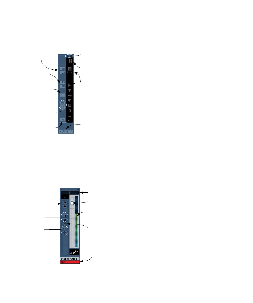
The common panel
The common panel appears to the left in the mixer windows
and contains settings for changing the look and behavior of
the mixer, as well as global settings for all channels.
Global Mute and
Solo buttons
Global automation
Read/Write buttons
Resets the settings
to default (for all or
selected channels).
Channel settings copy/
paste, see “Copying
settings between audio
channels” on page 98.
Opens the VST Connections window, see
“The VST Connections
window” on page 11.
Toggles “All Wide” or “All
Narrow” channel strips in
the mixer.
Command Target settings,
see “About the Command
Target” on page 90.
“Can Hide” settings, see
“Showing/hiding individual
channels (the “Can Hide”
setting)” on page 89.
These indicator buttons select what channel types are
shown/hidden in the mixer.
Store/Remove View set buttons (+/-) and Select View
set pop-up, see “Channel
view sets” on page 89.
The output channels
The output busses you set up in the VST Connections
window are represented by output channels in the mixer.
They are shown in a separate “pane” (to the right of the
regular channel strips), with its own divider and horizontal
scrollbar. The output channel strip is very similar to other
audio channels.
Pan control
Mute and Solo
buttons
Read/Write
Automation
Bus volume fader
Bus level meter
• For information on how to set up input and output busses, see “VST Connections: Setting up input and output
busses” on page 9.
• How to route audio channels to busses is described on
“The output channels” on page 92.
• The Main Mix (the default output) bus is used for monitoring. For information about Monitoring, see “About moni-
toring” on page 13.
Basic mixing procedures
Setting volume in the mixer
In the mixer, each channel strip has a fader for volume
control.
• For audio channels, the faders control the volume of the
channels before they are routed directly or via a group
channel to an output bus.
• An output channel fader determines the master output
level of all audio channels routed to that output bus.
• MIDI channels handle fader volume changes in the mixer
by sending out MIDI volume messages to the connected instrument(s).
Connected instruments must be set to respond to MIDI messages (such
as MIDI volume in this case) for this to function properly.
• The fader settings are displayed numerically below the
faders, in dB for audio channels and in the MIDI volume 0
to 127 value range for MIDI channels.
You can click in the fader value fields and enter a volume setting by typing.
• To make fine volume adjustments, hold down [Shift]
when you move the faders.
• If you hold down [Ctrl]/[Command] and click on a fader,
it will be reset to its default value, i.e. 0.0 dB for audio
channels, or MIDI volume 100 for MIDI channels.
This reset to default values works for most mixer parameters.
Inserts and EQ
indicators and
Bypass buttons
Edit button
Clip indicator, see
“Setting input levels” on page 51.
92
The mixer
Page 93
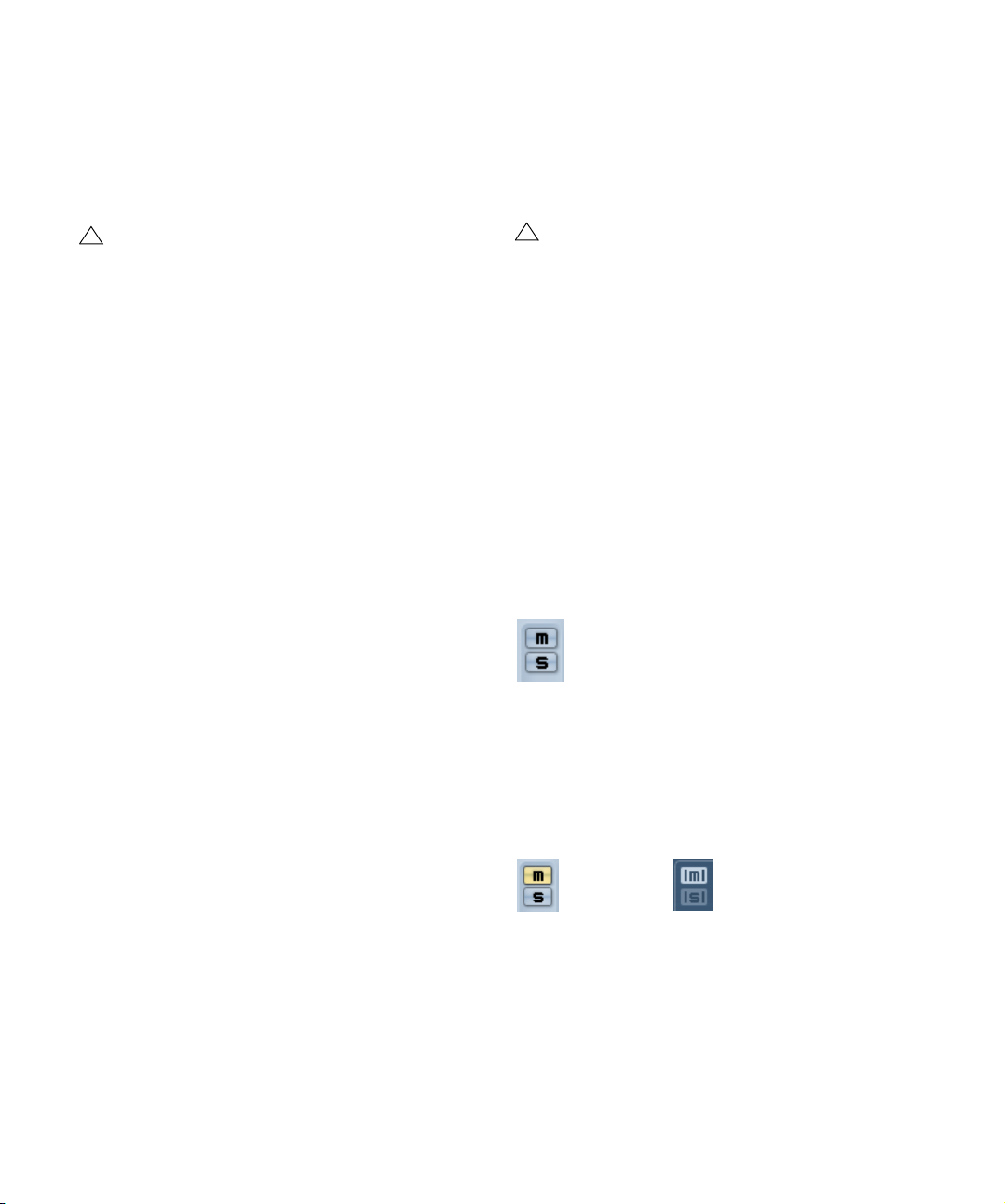
You can use the faders to set up a volume balance between the audio and MIDI channels and perform a manual
mix by moving the faders and other controls while playing
back. By using the Write function (see “Using Write/Read
automation” on page 135), you can automate the levels
and most mixer actions.
!
It is also possible to make static volume settings for
an event on the info line or with the volume handle
(see “About the volume handle” on page 64).
About the level meters for audio channels
When playing back audio in Cubase Essential, the level
meters in the mixer show the level of each audio channel.
• Directly below the level meter is a small level readout –
this shows the highest registered peak level in the signal.
Click this to reset the peak levels.
If the peak level of the audio goes above 0dB, the numerical level indicator will show a positive value (i.e. a value
above 0dB).
Cubase Essential uses 32 bit floating point processing internally, so there is virtually limitless headroom – signals
can go way beyond 0dB without clipping. Therefore:
Ö Having higher levels than 0dB for individual audio
channels is not a problem in itself. The audio quality will
not be degraded by this.
However, when many high level signals are mixed in an output bus, this
may require that you lower the output channel level a lot (see below).
Therefore it’s good practice to keep the max levels for individual audio
channels roughly around 0dB.
About the level meters for output channels
For the output channels, things are different. These channels have clip indicators.
• When you are recording, clipping can occur when the
analog signal is converted to digital in the audio hardware.
It is also possible to get clipping in the signal being recorded to disk. For
more about checking and setting input levels, see “Setting input levels”
on page 51.
• In the output busses, the floating point audio is converted to the resolution of the audio hardware. In the integer audio domain, the maximum level is 0dB – higher
levels will cause the clip indicator for each bus to light up.
If the clip indicators light up for a bus, this indicates actual clipping – digital distortion which should always be avoided.
!
If the clip indicator lights up for an output channel,
reset the clip indicator by clicking on it, and lower the
level until the indicator doesn’t light up.
About level meters for MIDI channels
The level meters for MIDI channels do not show actual volume levels. Instead, they indicate the velocity values of the
notes played back on MIDI tracks.
About MIDI tracks set to the same MIDI channel and
output
If you have several MIDI tracks set to the same MIDI channel (and routed to the same MIDI output), making volume
and pan settings for one of these MIDI tracks/mixer channels will also affect all other mixer channels set to the
same MIDI channel/output combination.
Using Solo and Mute
The Mute (top) and Solo buttons.
You can use the Mute and Solo buttons to silence one or
several channels. The following applies:
• The Mute button silences the selected channel.
Clicking the Mute button again un-mutes the channel. Several channels
can be muted simultaneously. A muted channel is indicated by a lit Mute
button and also by the lit Global Mute indicator on the common panel.
A muted channel in the mixer.
• Clicking the Solo button for a channel mutes all other
channels.
A soloed channel is indicated by a lit Solo button, and also by the lit Global Solo indicator on the common panel. Click the Solo button again to
turn off Solo.
A lit Global Mute indicator on the
common panel shows that one or
more channels are muted.
93
The mixer
Page 94
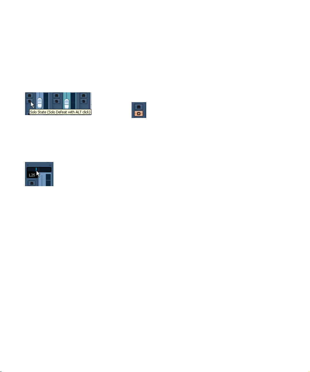
• Several channels can be soloed at the same time.
However, if you press [Ctrl]/[Command] and click the Solo button for a
channel, any other soloed channels will automatically be un-soloed (i.e.
this Solo mode is exclusive).
• [Alt]/[Option]-clicking a Solo button activates “Solo De-
feat” for that channel.
In this mode the channel will not be muted if you solo another channel. To
turn off Solo Defeat, [Alt]/[Option]-click the Solo button again.
[Alt]/[Option]-click a Solo button…
…to activate Solo Defeat for that channel.
• You can un-mute or un-solo all channels by clicking the
Mute or Solo indicator on the common panel.
Setting pan in the mixer
The pan control.
The pan controls in the mixer are used to position a channel between the left and right side of the stereo spectrum.
By default for stereo audio channels, pan controls the balance between the left and right channels. You can change
this in the Preferences. By selecting one of the other pan
modes (see below), you can set pan independently for the
left and right channel.
• To make fine pan adjustments, hold down [Shift] when
you move the pan control.
• To select the (default) center pan position, hold down
[Ctrl]/[Command] and click on the pan control.
• For MIDI channels, the pan control sends out MIDI pan
messages.
The result depends on how your MIDI instrument is set to respond to pan
– check your documentation for details.
About the “Stereo Pan Law” Preference (audio channels
only)
In the Project Setup dialog there is a pop-up menu named
“Stereo Pan Law”, on which you can select one of several
pan modes. This is related to the fact that without power
compensation, the power of the sum of the left and right
side will be higher (louder) if a channel is panned center
than if it is panned left or right.
To remedy this, the Stereo Pan Law setting allows you to
attenuate signals panned center, by -6, -4.5 or -3dB (default). Selecting the 0dB option effectively turns off constant-power panning. Experiment with the modes to see
which fits best in a given situation. You can also select
“Equal Power” on this pop-up menu, which means that the
power of the signal will remain the same regardless of the
pan setting.
Audio specific procedures
This section describes the options and basic procedures
regarding audio channels in the mixer.
Using Channel Settings
For each audio channel strip in the mixer and in the Inspector and Track list for each audio track, there is an Edit button (“e”).
Clicking this opens the VST Audio Channel Settings window. By default, this window contains:
• A section with eight insert effect slots (see “Audio effects” on
page 103).
• Four EQ modules and an associated EQ curve display (see
“Making EQ settings” on page 96).
• A section with eight effect sends (see “Audio effects” on page
103).
• A duplicate of the mixer channel strip
You can customize the Channel Settings window, by
showing/hiding the different panels and/or by changing
their order:
• To specify which panels should be shown/hidden, right-click
in the Channel settings window, and activate/deactivate the
respective options on the Customize View submenu on the
context menu.
94
The mixer
Page 95
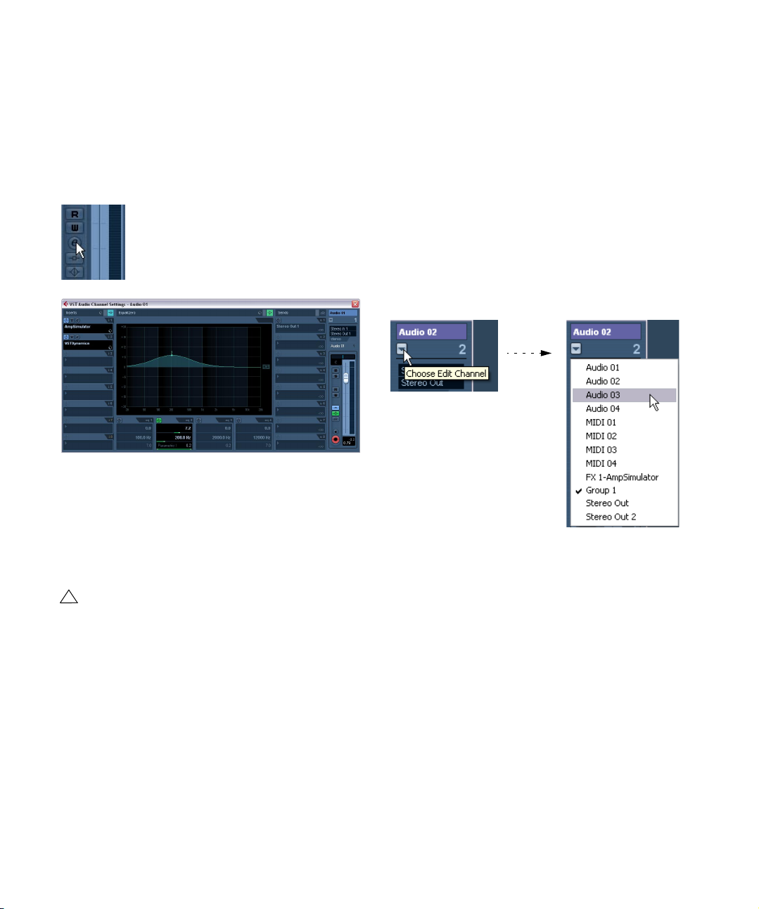
• To change the order of the panels, select “Setup…” on the
Customize View pop-up menu and use the “Move up” and
“Move Down” buttons.
For further information, see the chapter “Customizing” on
page 313.
Every channel has its own channel settings (although you
can view each in the same window if you like – see below).
Click the Edit button to open the
Channel Settings window.
The Channel Settings window is used for the following
operations:
• Apply equalization, see “Making EQ settings” on page 96.
• Apply send effects, see “Audio effects” on page 103.
• Apply insert effects, see “Audio effects” on page 103.
• Copy channel settings and apply them to another channel, see
“Copying settings between audio channels” on page 98.
!
All channel settings are applied to both sides of a
stereo channel.
Changing channels in the Channel Settings window
You can view any channel’s settings from a single window.
If the option “Sync Project and Mixer Selection” is activated in the Preferences (Editing–Project & Mixer page),
this can be done “automatically”:
• Open the Channel Settings window for a track and po-
sition it so that you can see both the Project window and
the Channel Settings window.
Selecting a track in the Project window automatically selects the corresponding channel in the mixer (and vice
versa). If a Channel Settings window is open, this will immediately switch to show the settings for the selected
channel. This allows you to have a single Channel Settings
window open in a convenient position on the screen, and
use it for all your EQ and channel effect settings.
You can also select a channel manually (thereby changing
what is shown in the open Channel Settings window).
Proceed as follows:
1. Open the Channel Settings window for any channel.
2. Open the Choose Edit Channel pop-up menu by
clicking the arrow button to the left of the channel number
at the top of the Fader view.
3. Select a channel from the pop-up to show the settings
for that channel in the open Channel Settings window.
• Alternatively, you can select a channel in the mixer by
clicking its channel strip (make sure not to click on a control as this will change the respective parameter setting instead).
This selects the channel, and the Channel Settings window is updated.
• To open several Channel Settings windows at the same
time, press [Alt]/[Option] and click the Edit buttons for the
respective channels.
95
The mixer
Page 96

Making EQ settings
Each audio channel in Cubase Essential has a built-in
parametric equalizer with up to four bands. There are several ways to view and adjust the EQs:
• By selecting the “Equalizers” or “Equalizer Curve” tab in
the Inspector.
The “Equalizers” section is similar to the “Equalizers” section in the
Channel Settings window, while the “Equalizer Curve” section shows a
display in which you can “draw” an EQ curve. Setting EQ in the Inspector is only possible for track-based audio channels.
Ö Note that by default, only the Equalizers tab is shown.
To display the Equalizer Curve tab, right-click on an Inspector tab (not in the empty area below the Inspector)
and activate the “Equalizer Curve” option.
• By using the Channel Settings window.
This offers both parameter sliders and a clickable curve display (the
Equalizer + Curve pane) and also lets you store and recall EQ presets.
!
Below we describe how to set up EQ in the Channel
Settings window, but the parameters are the same in
the Inspector.
The Equalizers + Curve pane in the Channel Settings window consists of four EQ modules with parameter sliders, an
EQ curve display and some additional functions at the top.
Using the parameter controls
1. Activate an EQ module by clicking its power button.
Although the modules have different default frequency values and different Q names, they all have the same frequency range (20Hz to 20kHz).
The only difference between the modules is that you can specify different
filter types for each individual module (see below).
2. Set the amount of cut or boost with the gain control –
the upper slider.
The range is ± 24 dB.
3. Set the desired frequency with the frequency slider.
This is the center frequency of the frequency range (20Hz to 20kHz) to
be cut or boosted.
4. Click on the lower slider (to the left) to open the filter
type pop-up menu and select the desired filter type.
The “eq1” and “eq4” bands can act as parametric, shelving or high/lowpass filters, while “eq2” and “eq3” will always be parametric filters.
5. Set the Q value with the lower slider (to the right).
This determines the width of the affected frequency range. Higher values
give narrower frequency ranges.
6. If needed, you can activate and make settings for up to
four modules.
• Note that you can edit the values numerically as well, by
clicking in a value field and entering the desired gain, frequency or Q value.
Using the curve display
When you activate EQ modules and make settings, you will
see that your settings are automatically reflected in the
curve display above. You can also make settings directly in
the curve (or combine the two methods any way you like):
1. To activate an EQ module, click in the curve display.
This adds a curve point and one of the modules below are activated.
2. Make EQ settings by dragging the curve point in the
display.
This allows you to adjust gain (drag up or down) and frequency (drag left
or right).
3. To set the Q parameter, press [Shift] and drag the
curve point up or down.
You will see the EQ curve become wider or narrower as you drag.
• You can also restrict the editing by pressing [Ctrl]/
[Command] (sets gain only) or [Alt]/[Option] (sets frequency only) while you drag the curve point.
96
The mixer
Page 97

4. To activate another EQ module, click somewhere else
in the display and proceed as above.
5. To turn off an EQ module, double-click its curve point
or drag it outside the display.
6. To mirror the eq curve on the x axis, click the button to
the right of the curve display.
The Inverse Equalizers button.
EQ bypass
Whenever one or several EQ modules are activated for a
channel, the EQ button will light up in green in the mixer
channel strip, Inspector (Equalizer and Channel sections),
Track list and Channel Settings window (top right corner
of the EQ section).
You can also bypass all EQ modules. This is useful, as it
allows you to compare the sound with and without EQ.
Proceed as follows:
• In the mixer, the Track list and in the Channel section in
the Inspector, click the EQs state button so that it turns
yellow.
To deactivate EQ Bypass, click the button again, so that it turns green
again.
• In the Inspector (Equalizers tab) and in the Channel
Settings window, click the Bypass button (next to the EQ
button) so that it turns yellow.
Click again to deactivate EQ Bypass mode.
Using EQ presets
Some useful basic presets are included with the program.
You can use them as they are, or as a starting point for further “tweaking”.
• To call up a preset, pull down the presets pop-up menu
in the Channel Settings window or in the Inspector and
select one of the available presets.
• To store the current EQ settings as a preset, select
“Store Preset” on the presets pop-up menu and enter the
desired name for the preset in the dialog that appears.
• To rename the selected preset, select “Rename Preset”
on the pop-up menu and enter a new name.
• To delete the selected preset, select “Remove Preset”
on the pop-up menu.
Ö You can also apply EQ (and Inserts) settings from
Track presets, see “Inserts and EQ settings from track
presets” on page 204.
EQ in the channel overview
If the “Channel” section is selected in the Inspector, you
will get an overview of which EQ modules, insert effects
and effect sends are activated for the channel.
By clicking the respective indicator (1 to 4), you can turn
the corresponding EQ module on or off.
EQ bypass in the mixer, the Channel Settings window and in the Inspector.
EQ reset
On the preset pop-up menu in the Channel Settings window and in the Inspector, you will find the Reset command.
Holding down [Alt]/[Option] and clicking this will turn off all
EQ modules and reset all EQ parameters to their default
values.
The channel overview in the Inspector.
97
The mixer
Page 98

Copying settings between audio channels
It is possible to copy all channel settings for an audio channel and paste them to one or several other channels. This
applies to all audio-based channel types. For example, you
can copy EQ settings from an audio track and apply these
to a group or VST Instrument channel, if you want them to
have the same sound.
Proceed as follows:
1. In the mixer, select the channel you want to copy set-
tings from.
You can also select channels with the Channel Select pop-up menu –
see “Changing channels in the Channel Settings window” on page 95.
2. Click the “Copy First Selected Channel’s Settings”
button on the common panel.
3. Select the channel(s) you want to copy the settings to
and click the “Paste Settings to Selected Channels” button (below the “Copy First Selected Channel Settings”
button).
The settings are applied to the selected channel(s).
• You can copy channel settings between different types
of channels, but only those channels will be used for
which corresponding settings are available in the target
channel:
• For example, since output channels don’t have send effects,
copying from them will leave the Sends settings in the target
channel unaffected.
Initialize Channel and Reset Mixer
The Initialize Channel button can be found in the lower
part of the Control Strip section in the Channel Settings
window (if this section is not shown in the Channel Settings window, open the context menu and select “Control
Strip” on the Customize View submenu). Initialize Channel
resets the selected channel to the default settings.
Similarly, the mixer common panel holds a Reset Mixer/
Reset Channels button – when you click this, you will be
asked whether you want to reset all channels or just the
selected channels.
The default settings are:
• All EQ, Insert and Send effect settings are deactivated and reset.
• Solo/Mute is deactivated.
• The fader is set to 0dB.
• Pan is set to center position.
Using group channels
You can route the outputs from multiple audio channels to
a group. This enables you to control the channel levels using one fader, apply the same effects and equalization to all
of them etc. To create a group channel, proceed as follows:
1. Select Add Track from the Project menu and select
“Group Channel” from the submenu that appears.
2. Select the desired channel configuration and click OK.
A group channel track is added to the Track list and a corresponding
group channel strip is added to the mixer. By default the first group channel strip is labeled “Group 1”, but you can rename it just like any channel
in the mixer.
3. Pull down the Output routing pop-up for a channel you
want to route to the group channel, and select the group
channel.
The output of the audio channel is now redirected to the selected group.
4. Do the same for the other channels you wish to route
to the group.
Settings for group channels
The group channel strips are (almost) identical to audio
channel strips in the mixer. The descriptions of the mixer
features earlier in this chapter apply to group channels as
well. Some things to note:
• You can route the output of a group to an output bus or
to another group.
You cannot route a group to itself. Routing is done with the Output Routing pop-up menu in the Inspector (select the subtrack for the Group in
the Track list).
• There are no Input Routing pop-ups, Monitor buttons or
Record Enable buttons for group channels.
This is because inputs are never connected directly to a group.
98
The mixer
Page 99

• Solo functionality is automatically linked for channels
routed to a group and the group channel itself.
This means that if you solo a group channel, all channels routed to the
group are automatically soloed as well. Similarly, soloing a channel
routed to a group will automatically solo the group channel.
• Mute functionality depends on the setting “Group Channels: Mute Sources as well” in the Preferences (VST page).
By default, when you mute a group channel no audio will pass through
the group. However, other channels that are routed directly to that group
channel will remain unmuted. If any of those channels have aux sends
routed to other group channels, FX channels or output busses, those will
still be heard.
If the option “Group Channels: Mute Sources as well” is activated in the
Preferences (VST page), muting a group channel will cause all other
channels directly routed to it to be muted as well. Pressing mute again
will unmute the group channel and all other channels directly routed to it.
Channels that were muted prior to the group channel being muted will
not remember their mute status and will be unmuted when the group
channel is unmuted.
!
The option “Group Channels: Mute Sources as well”
does not affect how mute automation is written.
Writing mute automation on a group channel only affects the group channel and not channels routed to
it. When writing the automation, you will see the
other channels being muted when this option is activated. However, upon playback, only the group
channel will respond to the automation.
One application of group channels is to use them as “effect
racks” – see the chapter “Audio effects” on page 103.
About output busses
Cubase Essential uses a system of input and output busses which are set up using the VST Connections dialog.
This is described in the chapter “VST Connections: Set-
ting up input and output busses” on page 9.
Output busses let you route audio from the program to the
outputs on your audio hardware.
Viewing the output busses in the mixer
Output busses are shown as output channels in a separate pane to the right in the mixer. You show or hide this
pane by clicking the Hide Output Channels button in the
mixer’s common panel to the left:
Each output channel resembles a regular audio channel
strip. Here you can do the following:
• Adjust master levels for all configured output busses using the
level faders.
• Add effects or EQ to the output channels (see the chapter
“Audio effects” on page 103).
MIDI specific procedures
This section describes basic procedures for MIDI channels in the mixer.
Using Channel Settings
For each MIDI channel strip in the mixer (and MIDI track in
the Track list or the Inspector), there is an Edit (“e”) button.
Clicking this opens the MIDI Channel Settings window.
By default, this window contains a duplicate of the mixer
channel strip, a section with four MIDI inserts and a section with four MIDI send effects.
You can customize the Channel Settings window, by
showing/hiding the different panels and/or by changing
their order:
• To specify, which panels should be shown/hidden, right-click
in the Channel settings window, and activate/deactivate the
respective options on the Customize View submenu on the
context menu.
• To change the order of the panels, select “Setup” on the Customize View pop-up menu and use the “Move up” and “Move
Down” buttons in the dialog that opens.
99
The mixer
Page 100

Every MIDI channel has its own channel settings.
The MIDI Channel Settings window
Utilities
Link/Unlink channels
This function is used to “link” selected channels in the
mixer so that any change applied to one channel will be
mirrored by all channels in that group. You can link as
many channels as you like, and you can also create as
many groups of linked channels as you like. To link channels in the mixer, proceed as follows:
1. Press [Ctrl]/[Command] and click on all the channels
you want to link.
[Shift]-clicking allows you to select a continuous range of channels.
3. Select “Link Channels” from the context menu.
• To unlink channels, select one of the linked channels and
select “Unlink Channels” from the Mixer context menu.
The channels are unlinked. Note that you do not need to select all the
channels that are linked, only one of them.
Ö It is not possible to remove individual channels from
Link status.
To make individual settings to a linked channel, press [Alt]/[Option] when
changing the setting.
What will be linked?
The following rules apply for linked channels:
• Only level, mute, solo, select, monitor and record enable
will be linked between channels.
Effect/EQ/pan/input and output routing settings are not linked.
• Any individual channel settings you have made before
linking will remain until you alter the same setting for any of
the linked channels.
For example, if you link three channels, and one of them was muted at the
time you applied the Link Channel function, this channel will remain muted
after linking. However, if you mute another channel all linked channels will
be muted. Thus, the individual setting for one channel is lost as soon as
you change the same parameter setting for any of the linked channels.
2. Right-click somewhere on the gray mixer panel.
The Mixer context menu appears.
100
The mixer
 Loading...