

Page 1

Plug-in Reference
Page 2

Cristina Bachmann, Heiko Bischoff, Marion Bröer, Sabine Pfeifer, Heike Schilling
The information in this document is subject to change without notice and does not represent a commitment on the part
of Steinberg Media Technologies GmbH. The software described by this document is subject to a License Agreement
and may not be copied to other media except as specifically allowed in the License Agreement. No part of this publication may be copied, reproduced, or otherwise transmitted or recorded, for any purpose, without prior written permission
by Steinberg Media Technologies GmbH. Registered licensees of the product described herein may print one copy of
this document for their personal use.
All product and company names are ™ or ® trademarks of their respective owners. Windows 7 is a registered trademark
or trademark of Microsoft Corporation in the United States and/or other countries. The Mac logo is a trademark used under license. Macintosh and Power Macintosh are registered trademarks. MP3SURROUND and the MP3SURROUND
logo are registered trademarks of Thomson SA, registered in the US and other countries, and are used under license
from Thomson Licensing SAS.
Release Date: December 16, 2010
© Steinberg Media Technologies GmbH, 2010.
All rights reserved.
Page 3

Table of Contents
Page 4

5 The included effect plug-ins
6 Introduction
6 Delay plug-ins
9 Distortion plug-ins
15 Dynamics plug-ins
23 EQ plug-ins
25 Filter plug-ins
30 Modulation plug-ins
37 Pitch Shift plug-ins
39 Reverb plug-ins
46 Spatial + Panner plug-ins
47 Surround plug-ins (Cubase only)
48 Tools plug-ins
74 The included VST instruments
75 Introduction
75 Embracer – Surround Pad Synthesizer
(Cubase only)
77 Groove Agent ONE
81 HALion Sonic SE
82 LoopMash
90 Monologue – Monophonic Analog Modeling
Synthesizer (Cubase only)
92 Mystic
100 Prologue
110 Spector
118 Diagrams
52 MIDI effects
53 Introduction
53 Arpache 5
54 Arpache SX
55 Auto LFO
56 Beat Designer
61 Chorder
63 Compressor
64 Context Gate
65 Density
65 Micro Tuner
65 MIDI Control
66 MIDI Echo
67 MIDI Modifiers
67 MIDI Monitor
68 Note to CC
68 Quantizer
69 StepDesigner
71 Track Control
73 Transformer
120 Index
4
Table of Contents
Page 5

1
The included effect plug-ins
Page 6
Introduction
This chapter contains descriptions of the included plug-in
effects and their parameters.
In Cubase, the plug-in effects are arranged in a number of
different categories. This chapter is arranged in the same
fashion, with the plug-ins listed in separate sections for
each effect category.
Ö Most of the included effects are compatible with
VST3, this is indicated by an icon in front of the name of
the plug-in as displayed in plug-in selection menus (for
further information, see the chapter “Audio effects” in the
Operation Manual).
Delay plug-ins
This section contains descriptions of the plug-ins in the
“Delay” category.
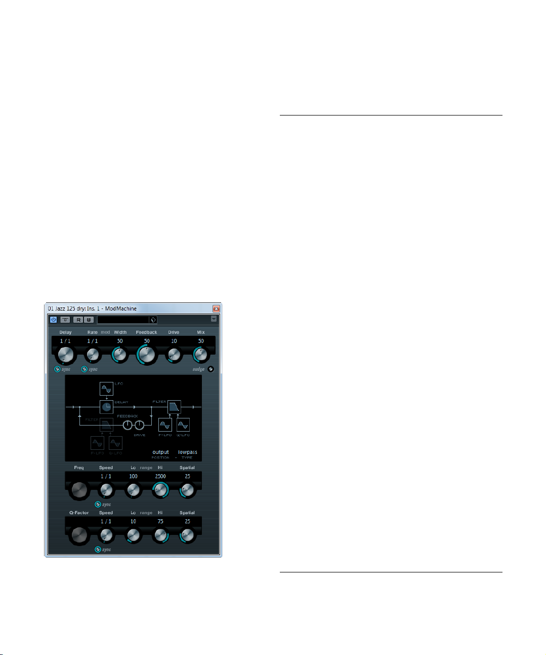
ModMachine (Cubase only)
ModMachine combines delay modulation and filter frequency/resonance modulation and can provide many
interesting modulation effects. It also features a Drive
parameter for distortion effects.
The following parameters are available:
Parameter Description
Delay If tempo sync is on, this is where you specify the base
Delay –
Sync button
Rate The Rate parameter sets the base note value for tempo
Rate –
Sync button
Width Sets the amount of delay pitch modulation. Note that al-
Feedback Sets the number of repeats for the delay.
Drive Adds distortion to the feedback loop. The longer the
Mix Sets the level balance between the dry and the wet sig-
Nudge button Clicking the Nudge button once will momentarily speed
Signal path
graphic and
Filter position
Filter type (in
graphic display)
Freq Sets the cutoff frequency for the filter. It is only available
Speed Sets the speed of the filter frequency LFO modulation.
Speed –
Sync button
note value for the delay (1/1–1/32, straight, triplet, or
dotted).
If tempo sync is off, the delay time can be set freely in
milliseconds.
The button below the Delay knob is used to switch
tempo sync for the Delay parameter on or off.
syncing the delay modulation (1/1 to 1/32, straight, trip
let, or dotted). If tempo sync is off, the rate can be set
freely.
The button below the Rate knob is used to switch tempo
sync for the Rate parameter on or off.
though the modulation affects the delay time, the sound
is mostly perceived as a vibrato or chorus-like effect.
Feedback, the more the delay repeats become distorted
over time.
nal. If ModMachine is used as a send effect, set this to
the maximum value (100
effect balance with the send.
up the audio coming into the plug-in, simulating an ana
log tape nudge type sound effect.
The filter can either be placed in the feedback loop of the
delay or in the output path of the effect (after the Drive
and Feedback parameters).
To switch between the “loop” and “output” positions,
click on the Filter section displayed in the graphic or
click on the Position field at the bottom right of the
graphic.
The Type button allows you to select a filter type. A lowpass, band-pass, and high-pass filter are available.
if tempo sync for the Speed parameter (see below) is
deactivated and the parameter is set to “0”.
When using tempo sync, the Speed parameter sets the
base note value for tempo syncing the modulation (1/1
to 1/32, straight, triplet, or dotted). If tempo sync is off,
the speed can be set freely.
The button below the Speed knob is used to switch
tempo sync for the Speed parameter on or off.
%) as you can control the dry/
-
-
The included effect plug-ins
6
Page 7
Parameter Description
Range Lo/Hi These knobs specify the range (in Hz) of the filter fre-
Spatial Introduces an offset between the channels to create a
Q-Factor Controls the resonance of the filter. It is only available if
Speed Sets the speed of the filter resonance LFO modulation.
Speed –
Sync button
Range Lo/Hi These knobs specify the range of filter resonance
Spatial Introduces an offset between the channels to create a
quency modulation. Both positive (e. g. Lo set to 50 and
Hi set to 10000) and negative (e.
Hi set to 500) ranges can be set. If tempo sync is off and
the Speed is set to zero, these parameters are inactive
and the filter frequency is controlled by the Freq parame
ter instead.
stereo panorama effect for the filter frequency modula
tion. Turn clockwise for a more pronounced stereo effect.
filter resonance LFO tempo sync is deactivated and the
Speed parameter (see below) is set to “0”. When using
tempo sync, the resonance is controlled by the Speed
and Range parameters.
When using tempo sync, the Speed parameter sets the
base note value for tempo syncing the modulation (1/1
to 1/32, straight, triplet, or dotted). If tempo sync is off,
the speed can be set freely.
The button below the Speed knob is used to switch
tempo sync for the Speed parameter on or off.
modulation. Both positive (e.
to 100) and negative (e.
50) ranges can be set. If tempo sync is off and the
Speed is set to zero, these parameters are inactive and
the filter resonance is controlled by the Q-Factor pa
rameter instead.
stereo panorama effect for the filter resonance modu
lation. Turn clockwise for a more pronounced stereo
effect.
g. Lo set to 5000 and
g. Lo set to 50 and Hi set
g. Lo set to 100 and Hi set to
-
-
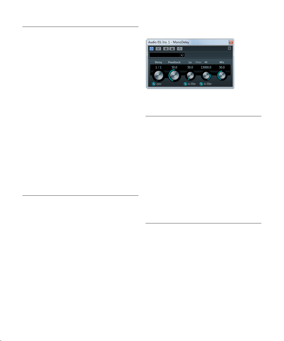
MonoDelay
-
-
This is a mono delay effect that can either be tempobased or use freely specified delay time settings.
The following parameters are available:
Parameter Description
Delay If tempo sync is on, this is where you specify the base
Sync button The button below the Delay knob is used to switch tempo
Feedback Sets the number of repeats for the delay.
Filter Lo This filter affects the feedback loop of the effect signal
Filter Hi This filter affects the feedback loop of the effect signal
Mix Sets the level balance between the dry and the wet sig-
note value for the delay (1/1–1/32, straight, triplet, or
dotted).
If tempo sync is off, the delay time can be set freely in
milliseconds.
sync on or off.
and allows you to roll off low frequencies from 10
Hz. The button below the knob activates/deactivates
800
the filter.
and allows you to roll off high frequencies from 20
down to 1.2
deactivates the filter.
nal. If MonoDelay is used as a send effect, set this to the
maximum value as you can control the dry/effect balance
with the send.
kHz. The button below the knob activates/
Hz up to
kHz
Ö The delay can also be controlled from another signal
source via the side-chain input. When the side-chain signal exceeds the threshold, the delay repeats are silenced.
When the signal drops below the threshold, the delay re
peats reappear. For a description of how to set up sidechain routing, see the chapter “Audio effects” in the Oper
ation Manual.
7
The included effect plug-ins
-
-
Page 8
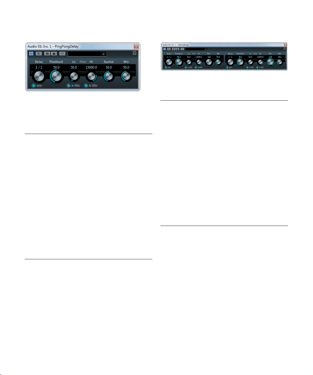
PingPongDelay
This is a stereo delay effect that alternates each delay repeat between the left and right channels. The effect can
either be tempo-based or use freely specified delay time
settings.
The following parameters are available:
Parameter Description
Delay If tempo sync is on, this is where you specify the base
Sync button The button below the Delay Time knob is used to switch
Feedback Sets the number of repeats for the delay.
Filter Lo This filter affects the feedback loop and allows you to roll
Filter Hi This filter affects the feedback loop and allows you to roll
Spatial Sets the stereo width for the left/right repeats. Turn
Mix Sets the level balance between the dry and the wet sig-
Ö The delay can also be controlled from another signal
source via the side-chain input. When the side-chain sig
nal exceeds the threshold, the delay repeats are silenced.
When the signal drops below the threshold, the delay re
peats reappear. For a description of how to set up sidechain routing, see the chapter “Audio effects” in the Oper
ation Manual.
note value for the delay (1/1–1/32, straight, triplet, or
dotted).
If tempo sync is off, the delay time can be set freely in
milliseconds.
tempo sync on or off.
off low frequencies up to 800
knob activates/deactivates the filter.
off high frequencies from 20
button below the knob activates/deactivates the filter.
clockwise for a more pronounced stereo “ping-pong” ef
fect.
nal. If PingPongDelay is used as a send effect, set this to
the maximum value as you can control the dry/effect bal
ance with the send.
Hz. The button below the
kHz down to 1.2 kHz. The
StereoDelay
StereoDelay has two independent delay lines which either
use tempo-based or freely specified delay time settings.
The following parameters are available:
Parameter Description
Delay 1 & 2 If tempo sync is on, this is where you specify the base
Sync button The buttons below the Delay knobs are used to turn
Feedback
1 & 2
Filter Lo
1 & 2
Filter Hi
1 & 2
Pan 1 & 2 These controls are used to set the stereo position for
Mix 1 & 2 Use these controls to set the level balance between the
-
Ö The delay can also be controlled from another signal
source via the side-chain input. When the side-chain signal exceeds the threshold, the delay repeats are silenced.
-
When the signal drops below the threshold, the delay re
peats reappear. For a description of how to set up sidechain routing, see the chapter “Audio effects” in the Oper
ation Manual.
-
-
-
note value for the delay (1/1–1/32, straight, triplet, or
dotted).
If tempo sync is off, the delay time can be set freely in
milliseconds.
tempo sync on or off for the respective delay.
The Feedback controls set the number of repeats for
each delay.
These filters affect the feedback loop and allow you to roll
off low frequencies up to 800
knobs activate/deactivate the filter.
These filters affect the feedback loop and allow you to roll
off high frequencies from 20
buttons below the knobs activate/deactivate the filter.
each delay.
dry and the wet signal. If StereoDelay is used as a send
effect, set them to the maximum value (100
control the dry/effect balance with the send.
Hz. The buttons below the
kHz down to 1.2 kHz. The
%) as you can
-
-
The included effect plug-ins
8
Page 9
Distortion plug-ins
This section contains descriptions of the plug-ins in the
“Distortion” category.
AmpSimulator
AmpSimulator is a distortion effect, emulating the sound
of various types of guitar amp and speaker cabinet combinations. A wide selection of amp and cabinet models is
available.
The following parameters are available:
Parameter Description
Amplifier
pop-up menu
Drive Controls the amount of amp overdrive.
Bass Tone control for the low frequencies.
Middle Tone control for the mid frequencies.
Treble Tone control for the high frequencies.
Presence Boosts or dampens the higher frequencies.
Volume Controls the overall output level.
Cabinet
pop-up menu
Damping Lo/Hi Further tone controls for shaping the sound of the se-
This pop-up menu is opened by clicking on the amplifier
name shown at the top of the amp section. It allows you
to select an amplifier model. The amp section can be by
passed by selecting “No Amp”.
This pop-up menu is opened by clicking on the cabinet
name shown at the top of the cabinet section. It allows
you to select a speaker cabinet model. This section can
be bypassed by selecting “No Speaker”.
lected speaker cabinet. Click on the values, enter a new
value and press the [Enter] key.
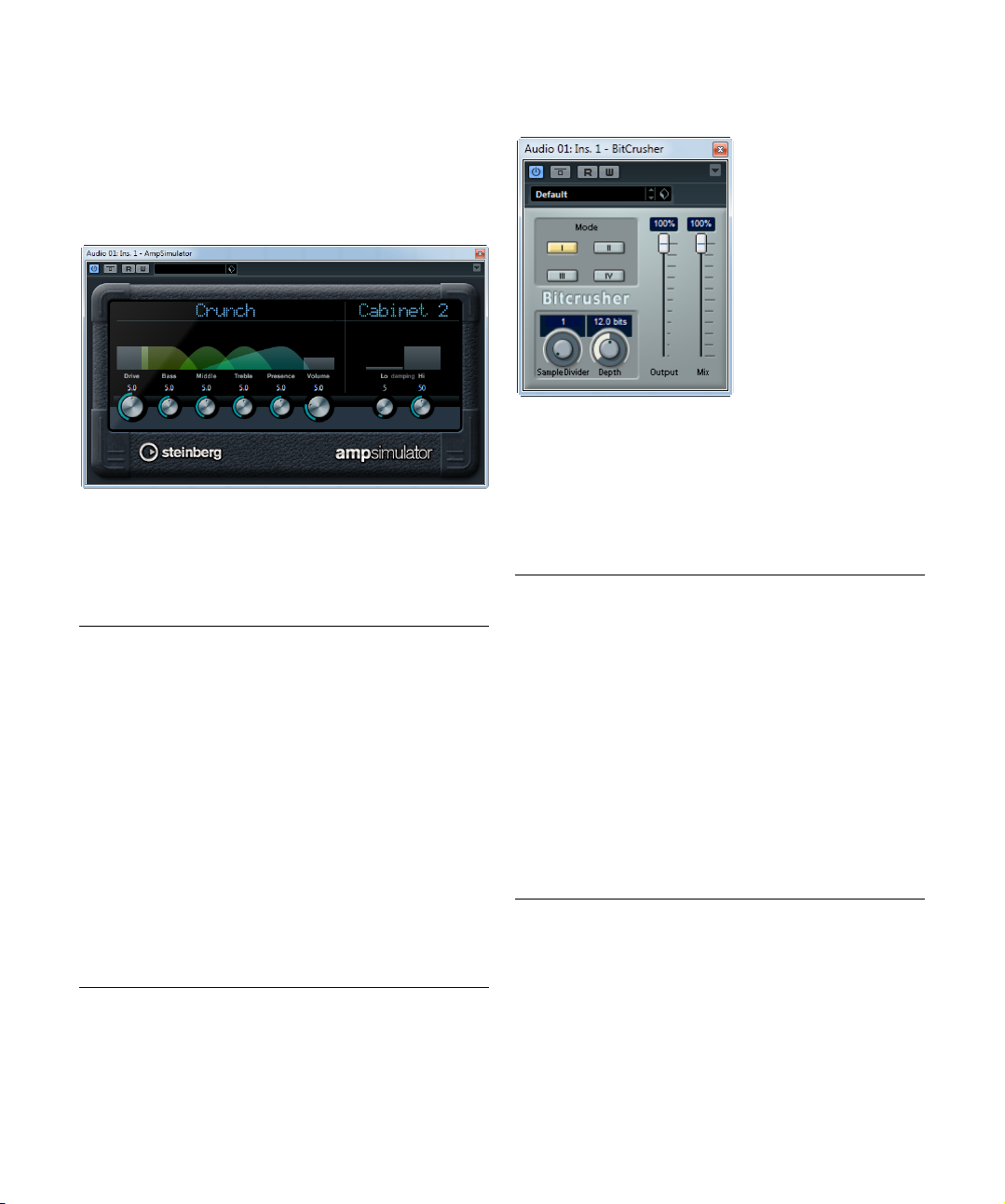
BitCrusher
If you are into lo-fi sound, BitCrusher is the effect for you.
It offers the possibility of decimating and truncating the in
put audio signal by bit reduction, to get a noisy, distorted
sound. You can for example make a 24-bit audio signal
sound like an 8 or 4-bit signal, or even render it completely
garbled and unrecognizable.
The following parameters are available:
Parameter Description
Mode Allows you to select one of the four operating modes of
Sample Divider Sets the amount by which the audio samples are deci-
-
Depth Defines the bit resolution. A setting of 24 gives the high-
Output slider Governs the output level from BitCrusher. Drag the slider
Mix slider Regulates the balance between the output from Bit-
BitCrusher. In each mode the plug-in sounds differently.
Modes I and III are nastier and noisier, while modes II and
IV are more subtle.
mated. At the highest setting (65), nearly all of the information describing the original audio signal is eliminated,
turning the signal into unrecognizable noise.
est audio quality, while a setting of 1 creates mostly
noise.
upwards to increase the level.
Crusher and the original audio signal. Drag the slider upwards for a more dominant effect, and downwards if you
want the original signal to be more prominent.
-
The included effect plug-ins
9
Page 10
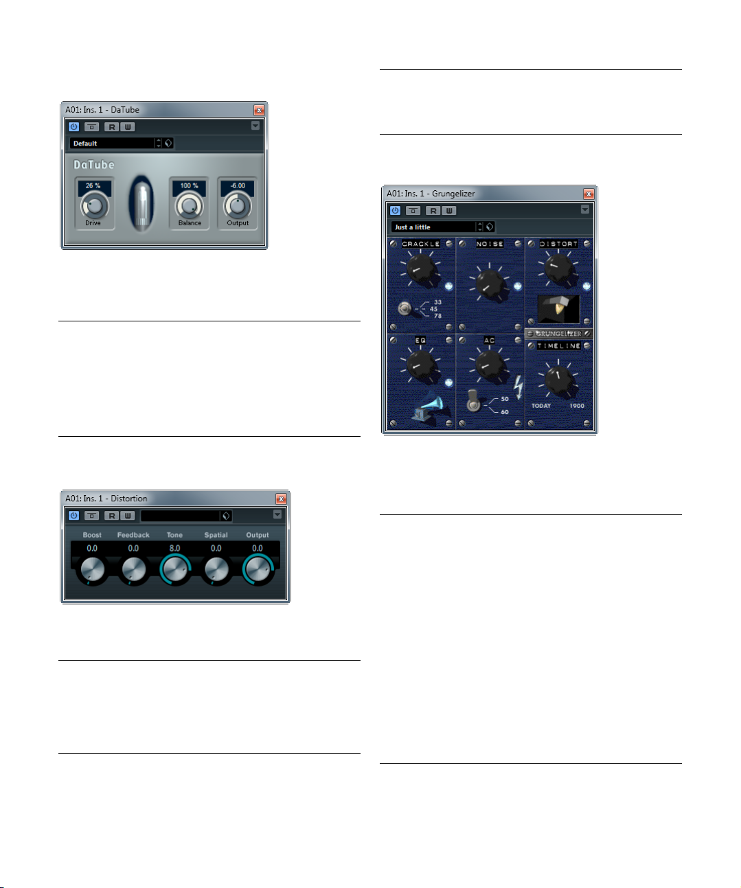
DaTube
This effect emulates the characteristic warm, lush sound
of a tube amplifier.
The following parameters are available:
Parameter Description
Drive Regulates the pre-gain of the “amplifier”. Use high values
Balance Controls the balance between the signal processed by
Output Adjusts the post-gain, or output level, of the “amplifier”.
if you want an overdriven sound just on the verge of
distortion.
the Drive parameter and the dry input signal. For maxi
mum drive effect, set this to its highest value.
-
Parameter Description
Spatial Changes the distortion characteristics of the left and right
Output Raises or lowers the signal going out of the effect.
channel, thus creating a stereo effect.
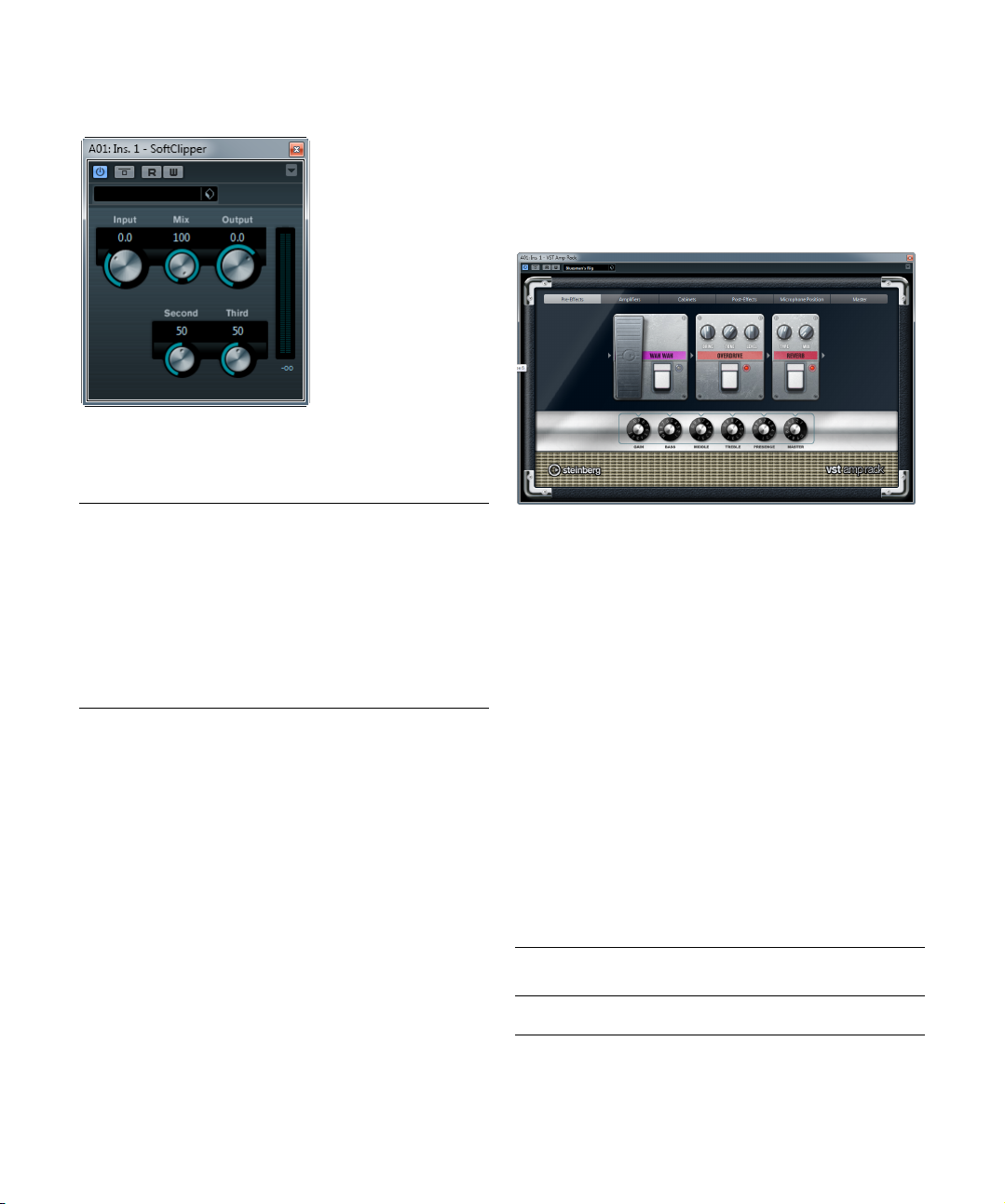
Grungelizer
Distortion
Distortion will add crunch to your tracks.
The following parameters are available:
Parameter Description
Boost Increases the distortion amount.
Feedback Feeds part of the output signal back to the effect input,
increasing the distortion effect.
Tone Lets you select a frequency range to which to apply the
distortion effect.
The included effect plug-ins
Grungelizer adds noise and static to your recordings –
kind of like listening to a radio with bad reception, or a
worn and scratched vinyl record. The following parameters are available:
Parameter Description
Crackle Adds crackle to create that old vinyl record sound. The
RPM switch When emulating the sound of a vinyl record, this switch
Noise Regulates the amount of static noise added.
Distort Adds distortion.
EQ Turn this knob to the right to cut off the low frequencies,
AC Emulates a constant, low hum of AC current.
Frequency
switch
Timeline Regulates the amount of overall effect. The farther to the
10
farther to the right you turn the knob, the more crackle is
added.
lets you set the RPM (revolutions per minute) speed of
the record (33/45/78 RPM).
and create a more hollow, lo-fi sound.
Sets the frequency of the AC current (50 or 60 Hz), and
thus the pitch of the AC hum.
right (1900) you turn the knob, the more noticeable the
effect.
Page 11
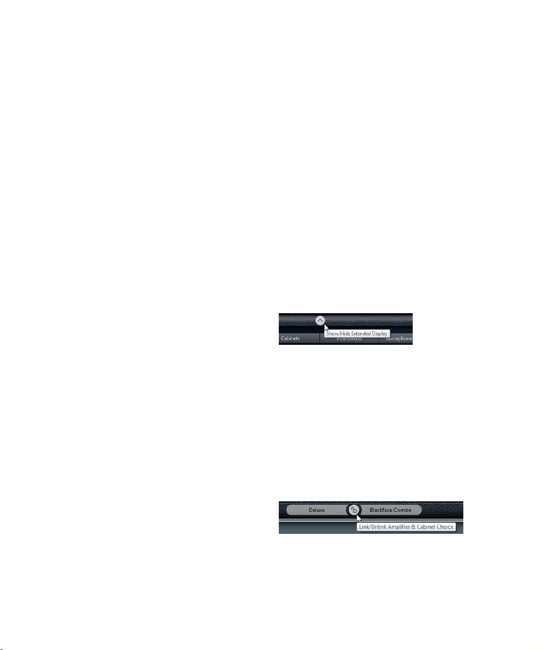
SoftClipper (Cubase only)
This effect adds soft overdrive, with independent control
over the second and third harmonic.
The following parameters are available:
Parameter Description
Input Regulates the pre-gain. Use high values if you want an
Mix Setting Mix to 0 means that no processed signal is added
Output Adjusts the post-gain, or output level.
Second Allows you to adjust the amount of the second harmonic
Third Allows you to adjust the amount of the third harmonic in
overdriven sound just on the verge of distortion.
to the original signal.
in the processed signal.
the processed signal.
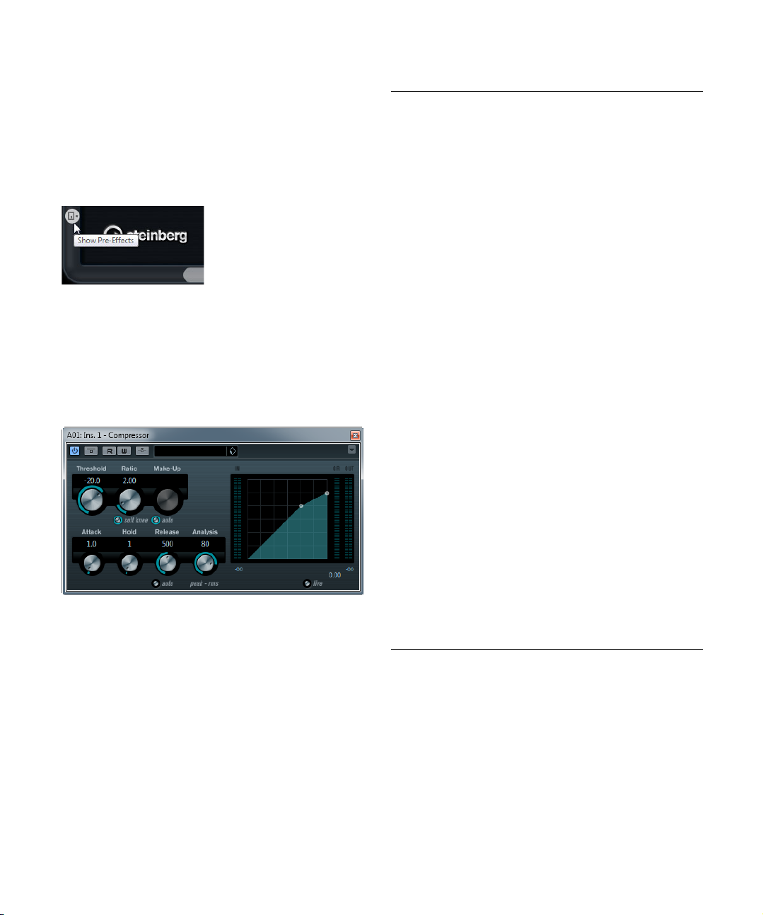
VST Amp Rack
The VST Amp Rack is a powerful guitar amp simulator. It
offers a choice of amplifiers and speaker cabinets that can
be combined with stomp box effects. The plug-in processes the mono sum of the channel and outputs a mono
or stereo signal, depending on the track configuration.
At the top of the plug-in panel there are six buttons, arranged according to the position of the corresponding elements in the signal chain. These buttons open different
pages in the Display section of the plug-in panel: PreEffects, Amplifiers, Cabinets, Post-Effects, Microphone
Position, and Master.
Below the Display section, the selected amplifier is
shown. The color and texture of the area below the amplifier indicate the selected cabinet.
Pre/Post-Effects
On the Pre-Effects and the Post-Effects pages, you can
select up to six common guitar effects. On both pages the
same effects are available, the only difference being the
position in the signal chain (before and after the amplifier).
On each page, every effect can be used once.
Each effect features an On/Off button known from stompbox effects, as well as individual parameters. The following
effects and parameters are available:
Effect Option Description
Wah Wah Pedal Controls the filter frequency sweep.
Volume Pedal Controls the level of the signal passing
11
The included effect plug-ins
through the effect.
Page 12

Effect Option Description
Compressor Intensity Changes the intensity of the compressor ef-
Chorus Rate Allows you to set the sweep rate.
Width Determines the depth of the chorus effect.
Phaser Rate Allows you to set the sweep rate.
Width Determines the width of the modulation effect
Flanger Rate Allows you to set the sweep rate.
Feedback Determines the character of the flanger effect.
Mix Sets the level balance between the dry and
Tremolo Rate Allows you to set the modulation speed.
Depth Governs the depth of the amplitude modula-
Octaver Direct Adjusts the mix of the original signal and the
Octave 1 Adjusts the level of the signal that is gener-
Octave 2 Adjusts the level of the signal that is gener-
Delay Delay Sets the delay time in milliseconds.
Feedback Sets the number of repeats for the delay.
Mix Sets the level balance between the dry and
Tape Delay Delay Tape Delay creates a delay effect known from
Feedback Sets the number of repeats for the delay.
Mix Sets the level balance between the dry and
fect.
This parameter can be synchronized to the
project tempo, see
Higher settings produce a more pronounced
effect.
This parameter can be synchronized to the
project tempo, see
between higher and lower frequencies.
This parameter can be synchronized to the
project tempo, see
Higher settings produce a more “metallic”
sounding sweep.
the wet signal.
This parameter can be synchronized to the
project tempo, see
tion.
generated voices. A value of 0 means only the
generated and transposed signal is heard. By
raising this value, more of the original signal is
heard.
ated one octave below the original pitch. A
setting of 0 means that the voice is muted.
ated two octaves below the original pitch. A
setting of 0 means that the voice is muted.
This parameter can be synchronized to the
project tempo, see
the wet signal.
tape machines. The Delay parameter sets the
delay time in milliseconds.
This parameter can be synchronized to the
project tempo, see
the wet signal.
“Sync mode” on page 13.
“Sync mode” on page 13.
“Sync mode” on page 13.
“Sync mode” on page 13.
“Sync mode” on page 13.
“Sync mode” on page 13.
Effect Option Description
Tape
Ducking
Delay
Overdrive Drive Overdrive creates a tube-like overdrive effect.
Fuzz Boost Fuzz creates a rather harsh distortion effect.
Gate Threshold Determines the level where Gate is activated.
Equalizer Low Changes the level of the low-frequency por-
Reverb Type A convolution-based reverb effect. The Type
Delay Tape Ducking Delay creates a delay effect
Feedback Sets the number of repeats for the delay.
Duck Works like an automatic mix parameter. If the
Tone Works as a filter effect on the added harmon-
Level Adjusts the output level.
Tone Works as a filter effect on the added harmon-
Level Adjusts the output level.
Release Sets the amount of time it takes for the gate to
Middle Changes the level of the mid-frequency por-
High Changes the level of the high-frequency por-
Mix Sets the level balance between the dry and
known from tape machines with a ducking pa
rameter. The Delay parameter sets the delay
time in milliseconds.
This parameter can be synchronized to the
project tempo, see
level of the input signal is high, the portion of
the effect signal is lowered, i.
internal mix value).
If the level of the input signal is low, the portion of the effect signal is raised (high internal
mix value). This way the delayed guitar signal
stays rather dry during loud or intensely played
passages.
The higher the Drive value, the more harmon
ics are being added to the output signal of this
effect.
ics.
The higher the Boost value, the more distor
tion is being created.
ics.
Signal levels above the set threshold trigger
the gate to open, and signal levels below the
set threshold close the gate.
close.
tion of the incoming signal (from -12 dB to
12
dB).
tion of the incoming signal (from -12 dB to
dB).
12
tion of the incoming signal (from -12 dB to
dB).
12
parameter allows you to switch between dif
ferent reverb types (Studio, Hall, Plate, and
Room).
the wet signal.
“Sync mode” on page 13.
e. ducked (low
-
-
-
-
The included effect plug-ins
12
Page 13

Sync mode
!
For some controls, the sync mode can be activated to
synchronize the corresponding parameter with the tempo
of the host application. These plug-in parameters are then
used to specify the base note value for tempo syncing
(1/1 to 1/32, straight, triplet, or dotted).
The names of these parameters are underlined. Click on a
control knob to activate/deactivate tempo sync. An LED at
the top right of the knob indicates that Sync mode is active. You can then select a base note value for tempo
syncing from the pop-up menu above the control.
Using effects
• To insert a new effect, click the plus button that appears
when hovering with the mouse over an empty plug-in slot
or over one of the arrows before or after a used effect slot.
• To remove an effect from an effect slot, click on the effect name and select “None” from the pop-up menu.
• To change the order of the effects in the chain, click on
an effect and drag it to another position.
• To activate or deactivate an effect, click on the pedallike button below the effect’s name.
When an effect is active, the LED next to the button is lit.
Pre-effects are always mono, while post-effects can
be mono or stereo, depending on the track configuration.
Ö Using the Quick Controls in Cubase, you can conveniently set up an external MIDI device such as a foot controller to control the VST Amp Rack effects. For more
information, see the chapter “Track Quick Controls” in the
Operation Manual.
Amplifiers
The amps available on the Amplifiers page were modeled
on real-life amplifiers. Each amp features settings typical
for guitar recording, such as gain, equalizers, and master
volume. The sound-related parameters (Bass, Middle, Tre
ble, and Presence) have a significant impact on the overall
character and sound of the corresponding amp.
The following amp models are available:
• Plexi – Classic British rock tone; extremely transparent sound,
very responsive.
• Plexi Lead – British rock tone of the 70’s and 80’s.
• Diamond – The cutting edge hard rock and metal sounds of
the 90’s.
• Blackface – Classic American clean tone.
• Tweed – Clean and crunchy tones; originally developed as a
bass amp.
• Deluxe – American crunch sound coming from a rather small
amp with a big tone.
• British Custom – Produces the sparkling clean or harmoni-
cally distorted rhythm sounds of the 60’s.
The different amps keep their settings when you switch
models. However, if you want to use the same settings after reloading the plug-in, you need to set up a preset.
Using amplifiers
• To switch amps on the Amplifiers page, simply click on
the model that you want to use.
• Select “No Amplifier” if you only want to use the cabinets and effects.
Cabinets
The cabinets available on the Cabinets page simulate
real-life combo boxes or speakers. For each amp, a corresponding cabinet type is available. However, you can
combine amps and cabinets at will.
Using cabinets
• To switch cabinets on the Cabinets page, simply click
on the model that you want to use. Select “No Cabinet” if
you only want to use the amps and effects.
• If you select “Link Amplifier & Cabinet Choice”, the
plug-in automatically selects the cabinet corresponding to
the selected amp model.
Microphone Position
On the Microphone Position page, you can choose be-
tween 7 positions to place the microphone. These positions result from two different angles (center and edge)
and three different distances from the speaker, as well as
an additional center position at an even greater distance
from the speaker.
The included effect plug-ins
13
Page 14
You can choose between two microphone types: a largediaphragm condenser microphone and a dynamic microphone. Crossfading between the characteristics of the
two microphones is also possible.
Placing the microphone
• To select a microphone position, simply click on the
corresponding ball in the graphic.
The selected position is marked in red.
• To select one of the microphone types or blend between the two types, turn the Mix control between the two
microphones.
View settings
Two differents views for the VST Amp Rack plug-in panel
are available: the default view and a compact view, which
takes up less screen space.
In the default view, you can use the top buttons to open
the corresponding page in the Display section above the
amp controls. In the compact view the page display is hid
den from view. You can still change the amp settings and
switch amps or cabinets using the mouse wheel.
• In the default view, you can horizontally resize the plugin panel by clicking and dragging the edges or corners.
-
Master
Use the Master page to fine-tune the sound. There is an
additional three-band Equalizer, a Tuner, and a Master
level control for the output of the plug-in.
Using the Master controls
• To activate/deactivate the Equalizer, click the pedal-like
On/Off button.
When the Equalizer is active, the LED next to the button is lit.
• To activate/deactivate an equalizer band, click the corresponding Gain knob.
When a band is active, the LED to the left of the Gain knob is lit.
• To tune your guitar strings, click the pedal-like On/Off
button to activate the Tuner and play a string.
When the correct pitch is displayed and the row of LEDs below the digital is green, the string is tuned correctly. The more red LEDs on the left/
right are lit, the lower/higher the pitch.
• To mute the output signal of the plug-in, click the pedallike Master button.
When the LED is off, the output is muted. Use this to tune your guitar in
silence, for example.
• To change the volume of the output signal, use the
Level control in the Master section.
Using the hover controls
Hover controls are buttons that become visible on the
plug-in frame if the mouse pointer is positioned somewhere on the plug-in panel.
Switching between default and compact view
• To toggle between the different views, click the down/
up arrow button (Show/Hide Extended Display) at the top
center of the plug-in frame.
Changing the amplifier and cabinet selection in the
compact view
In the compact view, a hover control on the lower border
of the plug-in frame allows you to select different amplifier
and cabinet models.
• To select a different amplifier or cabinet, click the name
and select a different model from the pop-up menu.
• To lock the amplifier and cabinet combination, activate
the “Link/Unlink Amplifier & Cabinet Choice” button.
If you now select another amp model, the cabinet selection follows.
However, if you select a different cabinet model, the lock is deactivated.
The included effect plug-ins
14
Page 15
Previewing effect settings
In both views, you can show a preview of the pre- and
post-effects that you selected on the corresponding
pages:
• Click and hold the Show Pre-Effects or Show Post-Effects button at the bottom left or right (respectively) of the
plug-in frame.
Dynamics plug-ins
This section contains descriptions of the plug-ins in the
“Dynamics” category.
Compressor
Compressor reduces the dynamic range of the audio, making softer sounds louder or louder sounds softer, or both.
Compressor features separate controls for threshold, ratio,
attack, hold, release and make-up gain parameters. Com
pressor features a separate display that graphically illustrates the compressor curve shaped according to the
Threshold and Ratio parameter settings. Compressor also
features a Gain Reduction meter that shows the amount of
gain reduction in dB, Soft knee/Hard knee compression
modes and a program-dependent Auto feature for the Re
lease parameter.
The following parameters are available:
Parameter Description
Threshold
(-60 to 0 dB)
Ratio
(1:1 to 8:1)
Soft Knee
button
Make-up
(0 to 24 dB or
Auto mode)
Attack
(0.1 to
ms)
100
Hold
(0 to
ms)
5000
Release
(10 to
ms or
1000
Auto mode)
Analysis
(0 to 100)
(Pure Peak to
Pure RMS)
Live button When this button is activated, the “look ahead” feature of
Ö The compression can also be controlled from another
Determines the level where Compressor “kicks in”. Signal
levels above the set threshold are affected, but signal lev
els below are not processed.
Sets the amount of gain reduction applied to signals over
the set threshold. A ratio of 3:1 means that for every 3
the input level increases, the output level will increase by
only 1
dB.
If this button is off, signals above the threshold are compressed instantly according to the set ratio (hard knee).
When Soft Knee is activated, the onset of compression is
more gradual, producing a less drastic result.
This parameter is used to compensate for output gain loss,
caused by compression. If the Auto button is activated, the
knob becomes dark and the output is automatically ad
justed for gain loss.
Determines how fast Compressor will respond to signals
above the set threshold. If the attack time is long, more of
the early part of the signal (attack) passes through unpro
cessed.
Sets the time the applied compression will affect the signal
after exceeding the threshold.
Short hold times are useful for “DJ-style” ducking, while
longer hold times are required for music ducking, e.
when working on a documentary film.
Sets the amount of time it takes for the gain to return to its
original level when the signal drops below the threshold
level. If the Auto button is activated, Compressor will auto
matically find an optimal release setting that varies depending on the audio material.
Determines whether the input signal is analyzed according
to peak or RMS values (or a mixture of both). A value of 0 is
pure peak and 100 pure RMS. RMS mode operates using
the average power of the audio signal as a basis, whereas
Peak mode operates more on peak levels. As a general
guideline, RMS mode works better on material with few
transients such as vocals, and Peak mode better for per
cussive material, with a lot of transient peaks.
Compressor is disengaged. Look ahead produces more
accurate processing, but adds a certain amount of latency
as a trade-off. When Live mode is activated, there is no la
tency, which might be better for “live” processing.
signal source via the side-chain input. When the sidechain signal exceeds the threshold, the compression is
triggered. For a description of how to set up side-chain
routing, see the chapter “Audio effects” in the Operation
Manual.
-
-
dB
-
-
g.
-
-
-
The included effect plug-ins
15
Page 16
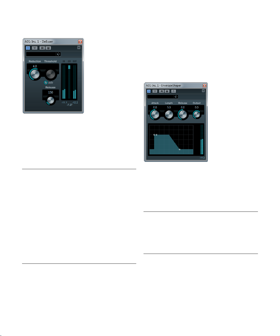
DeEsser (Cubase only)
A de-esser is used to reduce excessive sibilance, primarily
for vocal recordings. Basically, it is a special type of compressor that is tuned to be sensitive to the frequencies
produced by the “s” sound, hence the name de-esser.
Close proximity microphone placement and equalizing can
lead to situations where the overall sound is just right, but
there is a problem with sibilants.
The following parameters are available:
Parameter Description
Reduction Controls the intensity of the de-essing effect.
Threshold When the Auto Threshold option is deactivated, you can
Auto The Auto Threshold function automatically and continu-
Release Sets the amount of time it takes for the de-essing effect
Level meters Indicate the dB values of the input (IN) and output (OUT)
use this control to set a threshold for the incoming signal
level, above which the plug-in starts to reduce the sibilants.
ally chooses an optimum threshold setting independent
of the input signal.
The Auto Threshold function does not work for low-level
signals (< -30
such a file, set the threshold manually.
to return to zero when the signal drops below the thresh
old value.
signals as well as the value by which the level of the sibi
lant (or s-frequency) is reduced (GR). The gain reduction
meter shows values between 0
dB (the s-frequency level is lowered by 20 dB).
-20
db peak level). To reduce the sibilants in
dB (no reduction) and
Positioning the DeEsser in the signal chain
When recording a voice, the de-esser’s position in the
signal chain is usually located after the microphone preamp and before a compressor/limiter. This keeps the
compressor/limiter from unnecessarily limiting the overall
signal dynamics.
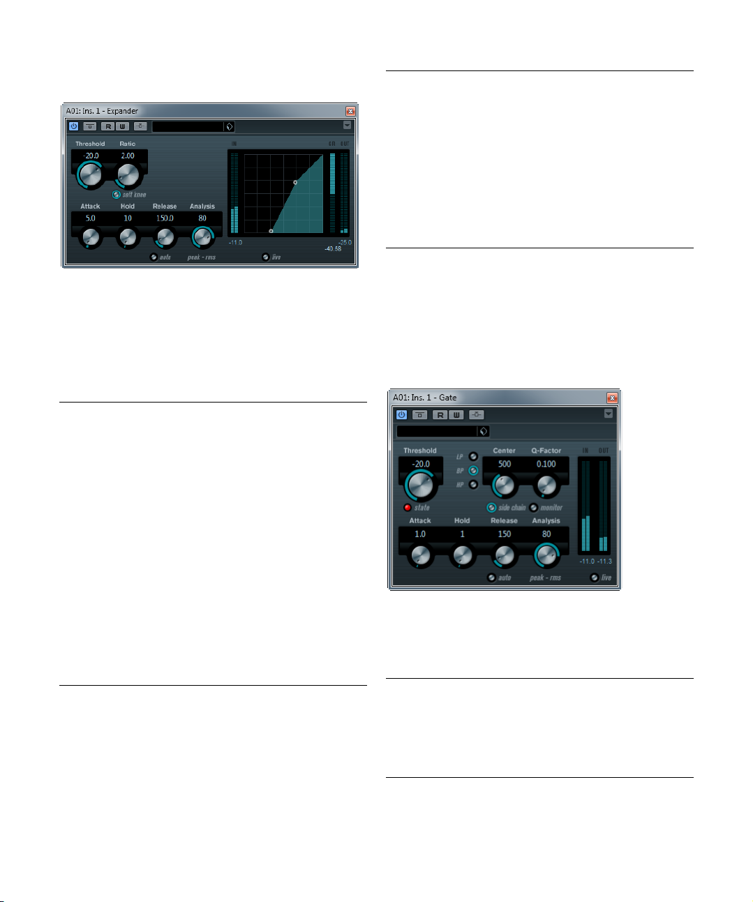
EnvelopeShaper
EnvelopeShaper can be used to cut or boost the gain of
the Attack and Release phase of audio material. You can
either use the knobs or drag the breakpoints in the graph
ical display to change parameter values. Be careful with
levels when boosting the gain and if needed reduce the
Output level to avoid clipping.
The following parameters are available:
Parameter Description
Attack (-20 to 20 dB) Changes the gain of the Attack phase of the
Length (5 to 200 ms) Determines the length of the Attack phase.
Release (-20 to 20 dB) Changes the gain of the Release phase of the
Output (-24 to 12 dB) Sets the output level.
signal.
signal.
-
The included effect plug-ins
16
Page 17
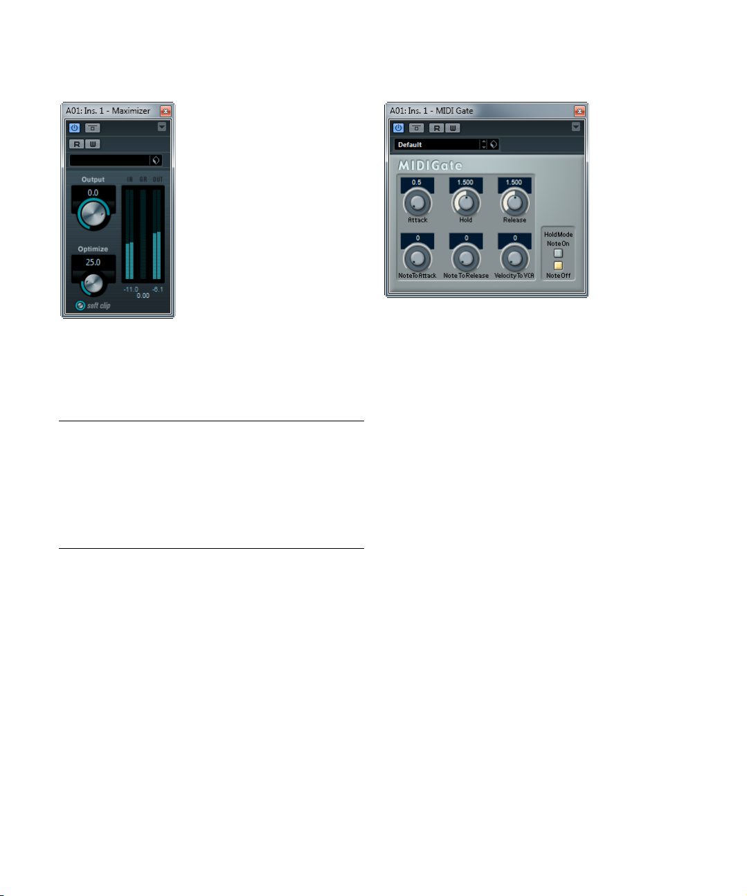
Expander (Cubase only)
Expander reduces the output level in relation to the input
level for signals below the set threshold. This is useful
when you want to enhance the dynamic range or reduce
the noise in quiet passages. You can either use the knobs
or drag the breakpoints in the graphical display to change
the Threshold and the Ratio parameter values.
The following parameters are available:
Parameter Description
Threshold
(-60 to 0 dB)
Ratio
(1:1 to 8:1)
Soft Knee
button
Attack (0.1 to
ms)
100
Hold (0 to
ms)
2000
Release
(10 to
1000
ms or
Auto mode)
Determines the level where expansion “kicks in”. Signal
levels below the set threshold are affected, but signal lev
els above are not processed.
Determines the amount of gain boost applied to signals
below the set threshold.
If this button is off, signals below the threshold are expanded instantly according to the set ratio (“hard knee”).
When Soft Knee is activated, the onset of expansion is
more gradual, producing a less drastic result.
Determines how fast Expander responds to signals below
the set threshold. If the attack time is long, more of the
early part of the signal (attack) passes through unpro
cessed.
Sets the time the applied expansion will affect the signal
below the Threshold.
Sets the amount of time it takes for the gain to return to its
original level when the signal exceeds the threshold level. If
the Auto button is activated, Expander will automatically
find an optimal release setting that varies depending on
the audio material.
-
Parameter Description
Analysis
(0 to 100)
(Pure Peak to
Pure RMS)
Live button When this button is activated, the “look ahead” feature of
Determines whether the input signal is analyzed according
to peak or RMS values (or a mixture of both). A value of 0 is
pure peak and 100 pure RMS. RMS mode operates using
the average power of the audio signal as a basis, whereas
Peak mode operates more on peak levels. As a general
guideline, RMS mode works better on material with few
transients such as vocals, and Peak mode better for per
cussive material, with a lot of transient peaks.
Expander is disengaged. Look ahead produces more ac
curate processing, but adds a certain amount of latency as
a trade-off. When Live mode is activated, there is no la
tency, which might be better for “live” processing.
Ö The expansion can also be controlled from another signal source via the side-chain input. When the side-chain
signal exceeds the threshold, the expansion is triggered.
For a description of how to set up side-chain routing, see
the chapter “Audio effects” in the Operation Manual.
Gate
-
Gating, or noise gating, silences audio signals below a set
threshold level. As soon as the signal level exceeds the set
threshold, the gate opens to let the signal through.
The following parameters are available:
Parameter Description
Threshold
(-60 to 0 dB)
State LED Indicates whether the gate is open (LED lights up in
Determines the level where Gate is activated. Signal levels above the set threshold trigger the gate to open, and
signal levels below the set threshold close the gate.
green), closed (LED lights up in red) or something in be
tween (LED lights up in yellow).
-
-
-
-
The included effect plug-ins
17
Page 18

Parameter Description
Filter buttons
(LP, BP, and
HP)
Side-Chain
button
Center (50 Hz
to 20000
Q-Factor (0.01
to 10000)
Monitor button Allows you to monitor the filtered signal.
Attack (0.1 to
ms)
1000
Hold
(0 to 2000 ms)
Release
(10 to 1000 ms
or Auto mode)
Analysis
(0 to 100)
(Pure Peak to
Pure RMS)
Live button When this button is activated, the “look ahead” feature of
When the Side-Chain button (see below) is activated,
you can use these buttons to set the filter type to either
low-pass, band-pass, or high-pass.
This button (below the Center knob) activates the sidechain filter. The input signal can then be shaped accord
ing to set filter parameters. Internal side-chaining can be
useful for tailoring how the Gate operates.
When the Side-Chain button is activated, this sets the
Hz)
center frequency of the filter.
When the Side-Chain button is activated, this sets the
resonance of the filter.
Sets the time it takes for the gate to open after being triggered. If the Live button (see below) is deactivated, it ensures that the gate will already be open when a signal
above the threshold level is played back. Gate manages
this by “looking ahead” in the audio material, checking for
signals loud enough to pass the gate.
Determines how long the gate stays open after the signal
drops below the threshold level.
Sets the amount of time it takes for the gate to close (after the set hold time). If the Auto button is activated, Gate
will find an optimal release setting, depending on the au
dio material.
Determines whether the input signal is analyzed according to Peak or RMS values (or a mixture of both). A value
of 0 is pure Peak and 100 pure RMS. RMS mode oper
ates using the average power of the audio signal as a basis, whereas Peak mode operates more on peak levels.
As a general guideline, RMS mode works better on mate
rial with few transients such as vocals, and Peak mode
better for percussive material, with a lot of transient
peaks.
Gate is disengaged. Look ahead produces more accurate
processing, but adds a certain amount of latency as a
trade-off. When Live mode is activated, there is no la
tency, which might be better for “live” processing.
-
Limiter
-
Limiter is designed to ensure that the output level never
exceeds a set output level, to avoid clipping in following
devices. Limiter can adjust and optimize the Release pa
rameter automatically according to the audio material, or it
can be set manually. Limiter also features separate meters
-
for the input, output and the amount of limiting (middle
meters).
The following parameters are available:
-
Parameter Description
-
Input
(-24 to +24 dB)
Output
(-24 to +6 dB)
Release
(0.1 to 1000 ms
or Auto mode)
Allows you to adjust the input gain.
Determines the maximum output level.
Sets the amount of time it takes for the gain to return to
its original level. If the Auto button is activated, Limiter
will automatically find an optimal release setting that var
ies depending on the audio material.
-
-
Ö The gate can also be controlled from another signal
source via the side-chain input. When the side-chain signal exceeds the threshold, the gate opens. For a description of how to set up side-chain routing, see the chapter
“Audio effects” in the Operation Manual.
The included effect plug-ins
18
Page 19
Maximizer
Maximizer is used to raise the loudness of audio material
without the risk of clipping. Optionally, there is a soft clip
function that removes short peaks in the input signal and
introduces a warm tube-like distortion to the signal.
The following parameters are available:
Parameter Description
Output
(-24 to +6 dB)
Optimize
(0 to 100)
Soft Clip
button
Determines the maximum output level. Should normally be
set to 0 (to avoid clipping).
Determines the loudness of the signal.
When this button is activated, Maximizer starts limiting (or
clipping) the signal “softly”, at the same time generating
harmonics which add a warm, tube-like characteristic to
the audio material.
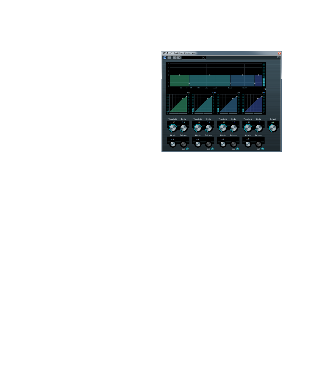
MIDI Gate
Gating, in its fundamental form, silences audio signals below a set threshold level. When a signal rises above the
set level, the gate opens to let the signal through while
signals below the set level are cut off. MIDI Gate, how
ever, is not triggered by threshold levels, but MIDI notes.
Hence it needs both audio and MIDI data to function.
Setting up
To set up MIDI Gate, proceed as follows:
1. Select the audio to be affected by MIDI Gate.
This can be audio material from any audio track, or even a live audio input
(provided you have a low latency audio card).
2. Select MIDI Gate as an insert effect for the audio
track.
The MIDI Gate control panel opens.
3. Select a MIDI track to control the MIDI Gate effect.
This can be an empty MIDI track or a MIDI track containing data, it does
not matter. However, if you wish to use MIDI Gate in realtime – as op
posed to using a recorded part – the track has to be selected for the effect to receive the MIDI output.
4. Open the Output Routing pop-up menu for the MIDI
track and select the MIDI Gate option.
The MIDI output from the track is now routed to the MIDI Gate effect.
What to do next depends on whether you are using live or
recorded audio and whether you are using realtime or re
corded MIDI. We will assume for the purposes of this
manual that you are using recorded audio, and play the
MIDI in realtime.
-
-
-
The included effect plug-ins
19
Page 20
5. Make sure the MIDI track is selected, and start playback.
6. Play a few notes on your MIDI keyboard.
As you can hear, the audio track material is affected by what you play on
your MIDI keyboard.
The following MIDI Gate parameters are available:
Parameter Description
Attack Determines how long it takes for the gate to open after
Hold Regulates how long the gate remains open after a note-
Release Determines how long it takes for the gate to close (in ad-
Note To Attack Determines to which extent the velocity values of the MIDI
Note To
Release
Velocity To
VCA
Hold Mode Use this switch to set the Hold Mode. In Note-On mode,
receiving a signal that triggers it.
on or note-off message (see Hold Mode below).
dition to the value set with the Hold parameter).
notes affect the attack. The higher the value, the more the
attack time increases with high note velocities. Negative
values give shorter attack times with high velocities. If you
do not wish to use this parameter, set it to the 0 position.
Determines to which extent the velocity values of the MIDI
notes affect the release. The higher the value, the more
the release time increases. If you do not wish to use this
parameter, set it to the 0 position.
Controls to which extent the velocity values of the MIDI
notes determine the output volume. At a value of 127 the
volume is controlled entirely by the velocity values, and at
a value of 0 the velocities have no effect on the volume.
the gate only remains open for the time set with the Hold
and Release parameters, regardless of the length of the
MIDI note that triggered the gate. In Note-Off mode, the
gate remains open for as long as the MIDI note plays, and
then the Hold and Release parameters are applied.
MultibandCompressor
(Cubase
The MultibandCompressor allows a signal to be split into
a maximum of four frequency bands, each with its own
freely adjustable compressor characteristic. The signal is
processed on the basis of the settings that you have made
in the Frequency Band and Compressor sections. You
can specify the level, bandwidth and compressor charac
teristics for each band by using the various controls.
The Frequency Band editor
The Frequency Band editor in the upper half of the panel is
where you set the width of the frequency bands as well as
their level after compression. Two value scales and a num
ber of handles are available. The vertical value scale to the
left shows the input gain level of each frequency band.
The horizontal scale shows the available frequency range.
The handles provided in the Frequency Band editor can
be dragged with the mouse. You use them to set the cor
ner frequency range and the input gain levels for each frequency bands.
• The handles at the sides are used to define the frequency
range of the different frequency bands.
• By using the handles on top of each frequency band, you can
cut or boost the input gain by +/- 15 dB after compression.
only)
-
-
-
The included effect plug-ins
20
Page 21
Bypassing frequency bands
Each frequency band can be bypassed using the B button
in each compressor section.
Soloing frequency bands
A frequency band can be soloed using the S button in
each compressor section. Only one band can be soloed
at a time.
Using the Compressor section
By moving breakpoints or using the corresponding knobs,
you can specify the Threshold and Ratio. The first break
point from which the line deviates from the straight diagonal will be the threshold point.
For each of the four bands the following compressor parameters are available:
Parameter Description
Threshold
(-60 to 0 dB)
Ratio
(1000 to 8000)
(1:1 to 8:1)
Attack
(0.1 to 100 ms)
Release
(10 to 1000 ms
or Auto mode)
Determines the level where Compressor “kicks in”. Signal levels above the set threshold are affected, but signal
levels below are not processed.
Determines the amount of gain reduction applied to signals over the set threshold. A ratio of 3000 (3:1) means
that for every 3
level increases by only 1
Determines how fast the compressor responds to signals above the set threshold. If the attack time is long,
more of the early part of the signal (attack) will pass
through unprocessed.
Sets the amount of time it takes for the gain to return to
its original level when the signal drops below the thresh
old level. If the Auto button is activated, the compressor
will automatically find an optimal release setting that var
ies depending on the audio material.
dB the input level increases, the output
dB.
The Output control
The Output knob controls the total output level that the
MultibandCompressor passes on to Cubase. The range is
from -24 to +24
dB.
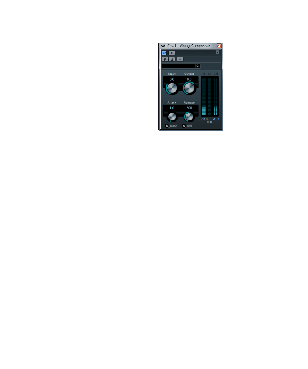
VintageCompressor (Cubase only)
This is modelled after vintage type compressors. This
compressor features separate controls for input and output gain, attack, and release. In addition, there is a Punch
mode which preserves the attack phase of the signal and
a program-dependent Auto feature for the Release pa
rameter.
The available parameters work as follows:
Parameter Description
Input
(-24 to 48 dB)
Output
-
(-48 to 24 dB)
Attack
(0.1 to 100 ms)
Punch
(On/Off)
Release
(10 to 1000 ms
or Auto mode)
In combination with the Output setting, this parameter
determines the compression amount. The higher the in
put gain setting and the lower the output gain setting, the
more compression is applied.
Sets the output gain.
Determines how fast the compressor responds. If the attack time is long, more of the early part of the signal (attack) passes through unprocessed.
When this is activated, the early attack phase of the signal is preserved, retaining the original “punch” in the audio material, even with short Attack settings.
Sets the amount of time it takes for the gain to return to
its original level. If the Auto button is activated, Vintage
Compressor will automatically find an optimal release set
ting that varies depending on the audio material.
-
-
-
Ö The compression can also be controlled from another
signal source via the side-chain input. When the sidechain signal exceeds the threshold, the compression is
triggered. For a description of how to set up side-chain
routing, see the chapter “Audio effects” in the Operation
Manual.
The included effect plug-ins
21
Page 22
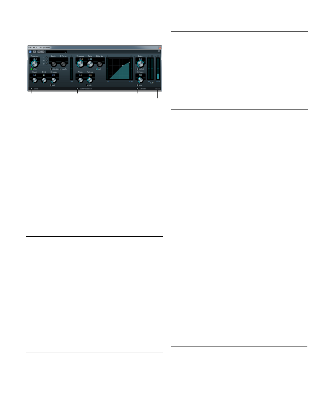
VSTDynamics
Limiter
Module Configuration
Gate
Compressor
VSTDynamics is an advanced dynamics processor. It
combines three separate processors: Gate, Compressor
and Limiter, covering a variety of dynamic processing
functions. The window is divided into three sections, con
taining controls and meters for each processor.
Activating the individual processors
You activate the individual processors using the buttons
at the bottom of the plug-in panel.
The Gate section
Gating, or noise gating, is a method of dynamic processing that silences audio signals below a set threshold level.
As soon as the signal level exceeds the set threshold, the
gate opens to let the signal through. The Gate trigger in
put can also be filtered using an internal side-chain.
The following parameters are available:
Parameter Description
Threshold
(-60 to 0 dB)
State LED Indicates whether the gate is open (LED lights up in
Side-Chain
button
LP (low-pass),
BP (band-pass),
HP (high-pass)
Center (50 to
22000
Hz)
Q-Factor (0.001
to 10000)
Determines the level where Gate is activated. Signal levels above the set threshold trigger the gate to open, and
signal levels below the set threshold close the gate.
green), closed (LED lights up in red) or something in be
tween (LED lights up in yellow).
This button activates the internal side-chain filter. You
can use this to filter out parts of the signal that might
otherwise trigger the gate in places you not want it to, or
to boost frequencies you wish to accentuate, allowing
for more control over the gate function.
These buttons set the basic filter mode.
Sets the center frequency of the filter.
Sets the resonance or width of the filter.
-
Parameter Description
Monitor
(On/Off)
Attack
(0.1 to 100 ms)
Hold
(0 to 2000 ms)
Release
(10 to 1000 ms
or Auto mode)
Input gain meter Shows the input gain.
Allows you to monitor the filtered signal.
Sets the time it takes for the gate to open after being
triggered.
Determines how long the gate stays open after the signal drops below the threshold level.
Sets the amount of time it takes for the gate to close (after the set hold time). If the Auto button is activated,
Gate will find an optimal release setting, depending on
the audio material.
The Compressor section
The compressor reduces the dynamic range of the audio,
-
making softer sounds louder or louder sounds softer, or
both. It works like a standard compressor with separate
controls for threshold, ratio, attack, release and make-up
gain. The compressor features a separate display that
graphically illustrates the compressor curve shaped ac
cording to the Threshold, Ratio and Make-Up Gain parameter settings. It also features meters for input gain and
gain reduction and a program-dependent Auto feature for
the Release parameter.
The available parameters work as follows:
Parameter Description
Threshold
(-60 to 0 dB)
Ratio
(1:1 to 8:1)
Make-Up
(0 to 24 dB)
Attack
(0.1 to 100 ms)
Release
(10 to 1000 ms
or Auto mode)
Graphical
display
Determines the level where the compressor “kicks in”.
Signal levels above the set threshold are affected, but
signal levels below are not processed.
Determines the amount of gain reduction applied to signals above the set threshold. A ratio of 3:1 means that for
every 3
dB the input level increases, the output level in-
creases by only 1 dB.
This parameter is used to compensate for output gain
loss, caused by compression. When the Auto button is
activated, gain loss is being compensated automatically.
Determines how fast the compressor responds to signals
above the set threshold. If the attack time is long, more of
the early part of the signal (attack) passes through un
processed.
Sets the amount of time it takes for the gain to return to
its original level when the signal drops below the thresh
old level. If the Auto button is activated, the compressor
will automatically find an optimal release setting that var
ies depending on the audio material.
Use the graphical display to graphically set the Threshold
and Ratio values. To the left and right of the graphical dis
play you will find two meters that show the amount of input gain and gain reduction in dB.
-
-
-
-
-
The included effect plug-ins
22
Page 23
The Limiter section
The limiter is designed to ensure that the output level
never exceeds a set threshold, to avoid clipping in following devices. Conventional limiters usually require very accurate setting up of the attack and release parameters to
prevent the output level from going beyond the set threshold level. The limiter adjusts and optimizes these parameters automatically according to the audio material. You
can also adjust the Release parameter manually.
The following parameters are available:
Parameter Description
Output
(-24 to +6 dB)
Soft Clip
button
Release
(10 to 1000 ms
or Auto mode)
Meters The three meters show the input gain (IN), the gain re-
Determines the maximum output level. Signal levels
above the set threshold are affected, but signal levels be
low are left unaffected.
If this button is activated, the limiter acts differently.
When the signal level exceeds -6
iting (or clipping) the signal “softly”, at the same time
generating harmonics which add a warm, tube-like char
acteristic to the audio material.
Sets the amount of time it takes for the gain to return to
its original level when the signal drops below the thresh
old level. If the Auto button is activated, the limiter will automatically find an optimal release setting that varies
depending on the audio material.
duction (GR) and the output gain (OUT).
dB, Soft Clip starts lim-
The Module Configuration button
Using the Module Configuration button in the bottom right
corner of the plug-in panel, you can set the signal flow or
der for the three processors. Changing the order of the
processors can produce different results, and the available options allow you to quickly compare what works
best for a given situation. Simply click the Module Configuration button to change to a different configuration. There
are three routing options:
• C-G-L (Compressor-Gate-Limit)
• G-C-L (Gate-Compressor-Limit)
• C-L-G (Compressor-Limit-Gate)
EQ plug-ins
This section describes the plug-ins in the “EQ” category.
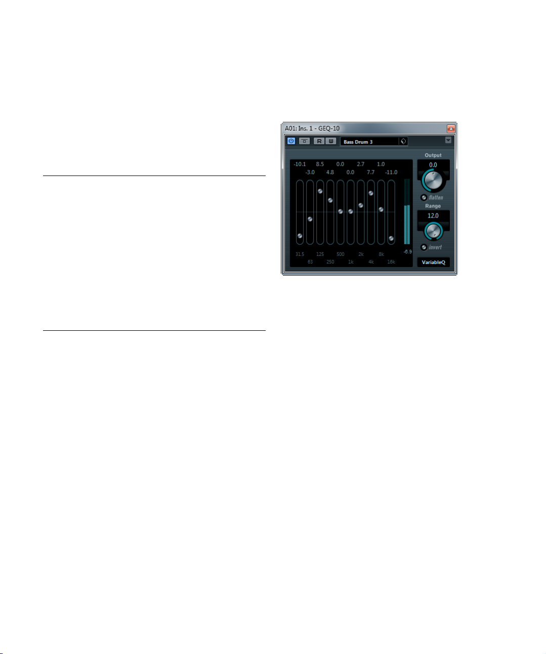
GEQ-10/GEQ-30 (Cubase only)
-
-
-
These graphic equalizers are identical in every respect except for the number of available frequency bands (10 and
30 respectively). Each band can be cut or boosted by up
dB, allowing for fine control of the frequency re-
to 12
sponse. In addition there are several preset modes available which can add “color” to the sound of the GEQ-10/
GEQ-30.
• You can draw response curves in the main display by
click-dragging with the mouse.
Note that you have to click on one of the sliders first before dragging
across the display. You can also point and click to change individual fre
quency bands, or enter values numerically by clicking on a gain value at
the top of the display.
• At the bottom of the window the individual frequency
bands are shown in Hz.
• At the top of the display the amount of cut/boost is
shown in dB.
-
The included effect plug-ins
23
Page 24
Apart from the frequency bands, the following parameters
are available:
Parameter Description
Output Controls the overall gain of the equalizer.
Flatten button Resets all the frequency bands to 0 dB.
Range Allows you to relatively adjust how much a set curve cuts
Invert button Inverts the current response curve.
Mode pop-up
menu
or boosts the signal. If the Range parameter is turned fully
clockwise, the range is +/-12
The filter mode set here determines how the various frequency band controls interact to create the response
curve, see below.
dB.
About the filter modes
On the pop-up menu in the lower right corner there are
several different EQ modes available. These modes can
add color or character to the equalized output in various
ways. The following filter modes are available:
Filter mode Description
True Resp Applies serial filters with an accurate frequency re-
Digi Stand In this mode the resonance of the last band depends on
Classic Applies a classic parallel filter structure where the re-
Variable Q Applies parallel filters where the resonance depends on
ConstQ u Applies parallel filters where the resonance of the first
ConstQ s Applies parallel filters where the resonance is raised
Resonant Applies serial filters where a gain increase of one band
sponse.
the sample rate.
sponse does not follow the set gain values accurately.
the amount of gain.
and last bands depends on the sample rate.
when boosting the gain and vice versa.
will lower the gain in adjacent bands.
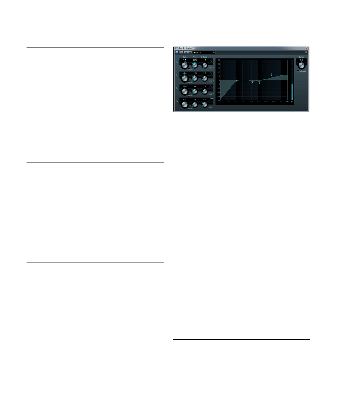
StudioEQ
This is a high-quality 4-band parametric stereo equalizer
with two fully parametric mid-range bands. The low and
high bands can act as either shelving filters (three types),
or as a Peak (band-pass) or Cut (low-pass/high-pass)
filter.
Making settings
1. Click the corresponding On button on the left of the
plug-in panel to activate any or all of the 4 equalizer bands
(Low, Mid 1, Mid 2, and High).
When a band is activated, the corresponding EQ point appears in the
EQ curve display.
2. Set the parameters for an activated EQ band.
This can be done in several ways:
• By using the knobs.
• By clicking on the numeric values and typing in new values.
• By using the mouse to drag points in the EQ curve display.
When using the mouse to change the parameter settings,
the following modifier keys can be used:
Modifier key Description
– When no modifier key is pressed and you drag an EQ
[Shift] Keep the [Shift] key pressed and drag the mouse to
[Alt]/[Option] Keep the [Alt]/[Option] key pressed and drag the
[Ctrl]/[Command] Keep the [Ctrl]/[Command] key pressed and drag the
point in the display, the Gain and Frequency parame
ters are adjusted simultaneously.
change the Q-factor of the corresponding EQ band.
mouse to change the frequency of the corresponding
EQ band.
mouse to change the gain value of the corresponding
EQ band.
-
The included effect plug-ins
24
Page 25
The following parameters are available:
Parameter Description
Band 1 Gain
(-20 to +24 dB)
Band 1 Inv button Inverts the gain value of the filter. Use this button to fil-
Band 1 Freq
(20 to 2000 Hz)
Band 1 Q-Factor
(0.5 to 10)
Band 1
Filter mode
Band 2 Gain
(-20 to +24 dB)
Band 2 Inv button Inverts the gain value of the filter (see the description
Band 2 Freq
(20 to 20000 Hz)
Band 2 Q-Factor
(0.5 to 10)
Band 3 Gain
(-20 to +24 dB)
Band 3 Inv button Inverts the gain value of the filter (see the description
Band 3 Freq
(20 to 20000 Hz)
Band 3 Q-Factor
(0.5 to 10)
Band 4 Inv button Inverts the gain value of the filter (see the description
Band 4 Gain
(-20 to +24 dB)
Band 4 Freq
(200 to 20000 Hz)
Band 4 Q-Factor
(0.5 to 10)
Sets the amount of cut/boost for the low band.
ter out unwanted noise. While looking for the frequency to omit, it sometimes helps to boost it in the
first place (set the filter to positive gain). After you
have found it, you can use the Inv button to cancel it
out.
Sets the frequency of the low band.
Controls the width or resonance of the low band.
For the low band, you can select between three types
of shelving filters, a Peak (band-pass), and a Cut (lowpass/high-pass) filter. When Cut mode is selected,
the Gain parameter is fixed.
-Shelf I adds resonance in the opposite gain direction
slightly above the set frequency.
-Shelf II adds resonance in the gain direction at the
set frequency.
-Shelf III is a combination of Shelf I and II.
Sets the amount of cut/boost for the mid 1 band.
of the Invert button for Band 1).
Sets the center frequency of the mid 1 band.
Sets the width of the mid 1 band: the higher this value,
the “narrower” the bandwidth.
Sets the amount of cut/boost for the mid 2 band.
of the Invert button for Band 1).
Sets the center frequency of the mid 2 band.
Sets the width of the mid 2 band: the higher this value,
the “narrower” the bandwidth.
of the Invert button for Band 1).
Sets the amount of cut/boost for the high band.
Sets the frequency of the high band.
Controls the width or resonance of the high band.
Parameter Description
Band 4
Filter mode
Output
(-24 to +24 dB)
Auto Gain button When this button is activated, the gain is automatically
For the high band, you can select between three types
of shelving filters, a Peak, and a Cut filter. When Cut
mode is selected, the Gain parameter is fixed.
-Shelf I adds resonance in the opposite gain direction
slightly below the set frequency.
-Shelf II adds resonance in the gain direction at the
set frequency.
-Shelf III is a combination of Shelf I and II.
This knob on the top right of the plug-in panel allows
you to adjust the overall output level.
adjusted, keeping the output level constant regardless
of the EQ settings.
Filter plug-ins
This section contains descriptions of the plug-ins in the
“Filter” category.
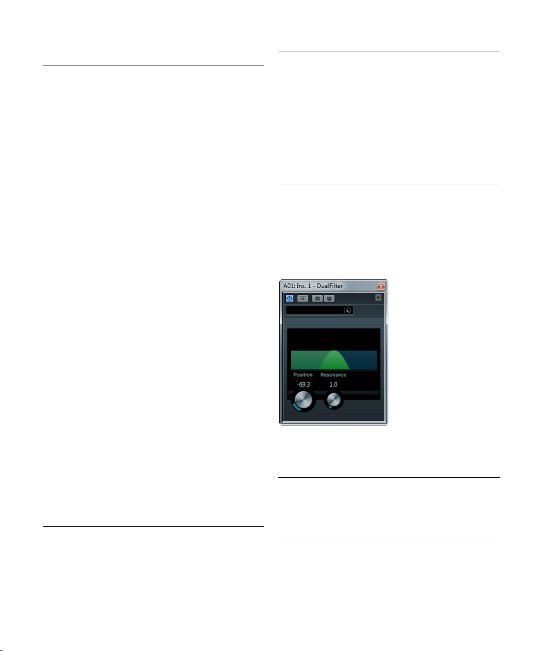
DualFilter
The DualFilter effect filters out certain frequencies while
allowing others to pass through.
The following parameters are available:
Parameter Description
Position Sets the filter cutoff frequency. If you set this to a nega-
Resonance Sets the sound characteristic of the filter. With higher val-
tive value, DualFilter will act as a low-pass filter. Positive
values cause DualFilter to act as a high-pass filter.
ues, a ringing sound is heard.
The included effect plug-ins
25
Page 26
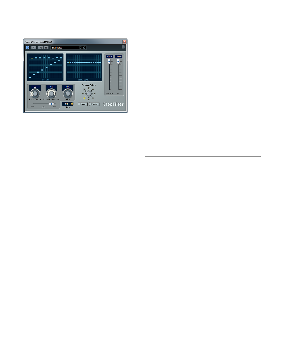
StepFilter
StepFilter is a pattern-controlled multimode filter that can
create rhythmic, pulsating filter effects.
General operation
StepFilter can produce two simultaneous 16-step patterns for the filter cutoff and resonance parameters, synchronized to the sequencer tempo.
Setting step values
• Setting step values is done by clicking in the pattern
grid windows.
• Individual step entries can be freely dragged up or
down the vertical axis, or directly set by clicking in an
empty grid box. By click-dragging left or right, consecutive
step entries are set at the pointer position.
• The horizontal axis shows the pattern steps 1 to 16 from
left to right, and the vertical axis determines the (relative)
filter cutoff frequency and resonance settings.
The higher up on the vertical axis a step value is entered, the higher the
relative filter cutoff frequency or filter resonance setting.
• By starting playback and editing the patterns for the
cutoff and resonance parameters, you can hear how your
filter patterns affect the sound source connected to StepFilter.
Selecting new patterns
• Created patterns are saved with the project, and up to 8
different cutoff and resonance patterns can be saved internally.
Both the cutoff and resonance settings are saved together in the 8 pattern slots.
• Use the Pattern Selector below the Resonance grid to
select a new pattern.
New patterns are all set to the same step value by default.
Using pattern copy and paste to create variations
You can use the Copy and Paste buttons below the Pattern Selector to copy a pattern to another pattern slot,
which is useful for creating variations on a pattern.
• Select the pattern you wish to copy, click the Copy button, select another pattern slot, and click Paste.
The pattern is copied to the new slot, and can now be edited to create
variations using the original pattern as a starting point.
StepFilter parameters
The following parameters are available:
Parameter Description
Base Cutoff Sets the base filter cutoff frequency. Values set in the
Base Resonance Sets the base filter resonance. Values set in the Reso-
Glide This will apply glide between the pattern step values,
Filter mode Use this slider to select a filter mode: low-pass (LP),
Sync button When the Sync button to the right of the Sync pop-up
Sync pop-up
menu (1/1 to
1/32, straight,
triplet, or dotted)
Output slider Sets the overall volume.
Mix slider Adjusts the mix between dry and processed signal.
Cutoff grid are relative to the Base Cutoff value.
nance grid are relative to the Base Resonance value.
Note that very high Base Resonance settings can pro
duce loud ringing effects at certain frequencies.
causing values to change more smoothly.
band-pass (BP), or high-pass (HP) (from left to right).
menu is activated (yellow), the pattern playback is syn
chronized with the project tempo.
Use this pop-up menu to set the pattern beat resolution, i. e. what note values the pattern will play in relation
to the tempo.
-
-
The included effect plug-ins
26
Page 27
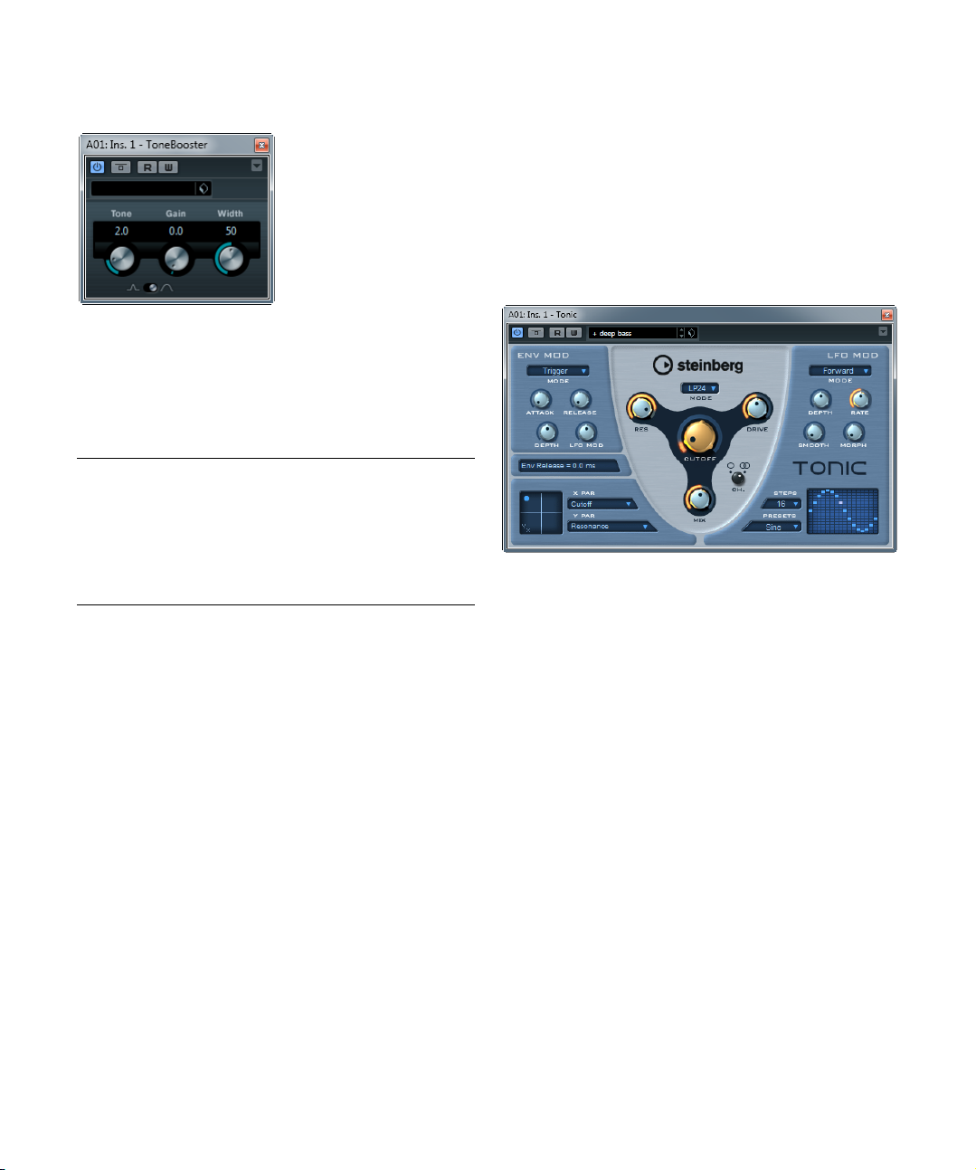
ToneBooster
ToneBooster is a filter that allows you to raise the gain in a
selected frequency range. It is particularly useful when
inserted before AmpSimulator in the plug-in chain (see
“AmpSimulator” on page 9), greatly enhancing the tonal
varieties available.
The following parameters are available:
Parameter Description
Tone Sets the center filter frequency.
Gain Allows you to adjust the gain of the selected frequency
range by up to 24
Width Sets the resonance of the filter.
Mode selector Sets the basic operational mode of the filter; Peak or
Band Mode.
dB.
Tonic (Cubase only)
Tonic is a versatile and powerful analog modeling filter
plug-in based on the filter design of the Monologue monophonic synthesizer. Its variable characteristics plus the
powerful modulation functions make it an excellent choice
for all current music styles. Designed to be more a cre
ative tool rather than a tool to fix audio problems, it can
add color and punch to your tracks while being light on
CPU usage.
Tonic has the following properties:
• Dynamic multimode analog modeling filter (mono/stereo).
• 24 dB low-pass, 18 dB low-pass, 12 dB low-pass, 6 dB
low-pass, 12 dB band-pass, and 12 dB high-pass modes.
• Adjustable drive and resonance up to self-oscillation.
• Envelope follower for dynamic filter control with an
audio signal.
• Audio and MIDI trigger modes.
• Powerful step LFO with smoothing and morphing.
• X/Y matrix pad for additional realtime modulation with
access to all Tonic parameters.
-
The included effect plug-ins
27
Page 28

Filter
In the Filter section at the center of the plug-in panel, the
following parameters are available:
Parameter Description
Mode pop-up
menu
Cutoff Sets the filter cutoff frequency. How this parameter oper-
Res Changes the resonance of the multi-mode filter. Full res-
Drive Adds a soft, tube-like saturation to the sound. As with an
Mix Sets the balance between dry and effect signal.
Channel
selector (Ch.).
Sets the filter type. Available filter types are: 24 dB low-
dB low-pass, 12 dB low-pass, 6 dB low-pass,
pass, 18
dB band-pass, and 12 dB high-pass.
12
ates is governed by the filter type.
onance puts the filter into self-oscillation.
analog filter, the amount of saturation also depends on
the input signal level.
Allows you to choose between mono or stereo operation.
When set to mono, the output signal of Tonic is mono re
gardless of the input signal.
Env Mod
In the Env Mod section, the following parameters are
available:
Parameter Description
Mode pop-up
menu
Attack Controls the attack time of the envelope. Higher attack
Release Controls the release time of the envelope. Higher release
Depth Controls the amount of envelope control applied to the
LFO Mod Using this parameter, the envelope level modulates the
Tonic offers three types of envelope modulation:
“Follow” tracks the input signal’s volume envelope for dy-
namic control of the filter cutoff.
“Trigger” uses the input signal to trigger the envelope
and have it run through a single envelope cycle.
“MIDI” uses any MIDI note to trigger the envelope. The
filter cutoff tracks the keys played on the keyboard. In ad
dition, velocities higher than 80 add an accent to the en-
velope by increasing the envelope depth and reducing
the decay time.
For MIDI control, set up a separate MIDI control track and
select “Tonic” from the Output Routing pop-up menu for
the track.
times result in slower rise times when the envelope is trig
gered.
times result in slower envelope tails.
filter cutoff level.
LFO speed. A rather stunning effect.
X/Y Pad
In the X/Y Pad at the bottom left of the plug-in panel, the
following parameters are available:
Parameter Description
X Par pop-up
menu
Y Par pop-up
menu
XY Pad Use the mouse to control any two of Tonic’s parameters
Sets the parameter to be modulated on the x-axis of the
XY Pad. All of Tonic’s parameters are available as desti
nations.
Sets the parameter to be modulated on the y-axis of the
XY Pad.
in combination. By moving the mouse horizontally you
control the x parameter, and by moving it vertically you
control the y parameter. You can also record controller
movements as automation data.
LFO Mod
-
In the LFO Mod section, the following parameters are
available:
Parameter Description
Mode pop-up
menu
Depth Controls the amount of LFO modulation applied to the fil-
Rate Controls the speed of the LFO modulation. The LFO rate
-
Smooth Controls the smoothing of the LFO steps. This works like
Morph Controls the playback value of the LFO step sequencer. It
-
Steps pop-up
menu
Presets
pop-up menu
Step Matrix Click into the Step Matrix to set the level for each of the
Sets the direction of the step LFO modulation. The available modes are: Forward, Reverse, Alternating, and
Random.
ter cutoff level.
is always in sync with the project tempo. An example: at a
rate of 4.00 steps per beat in a 4/4 time signature, the
step sequencer advances in 16th notes. At a rate of 4.00
beats per step in a 4/4 time signature the LFO advances
only one step per bar.
Note that the current LFO Rate is shown in the field below the Env Mod section.
a glide effect applied to the filter cutoff.
makes the LFO steps drift about randomly. Experiment
freely with the Morph parameter. As you return the knob
to its zero position, the step pattern returns to its original
setting.
Sets the number of steps played in sequence. Deactivated steps are grayed out in the Step Matrix.
Offers a number of step LFO waveform patterns. Choices
include: Sine, Sine+, Cosine, Triangle, Sawtooth,
Square, Random, and User (which is the pattern saved
with the respective program).
16 LFO steps. A higher amount results in a deeper filter
cutoff modulation. Click and drag along the matrix to
“draw” a waveform.
-
The included effect plug-ins
28
Page 29
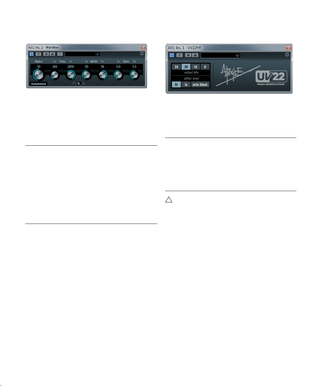
WahWah
!
Mastering – UV22HR
WahWah is a variable slope band-pass filter that can be
auto-controlled by a side-chain signal or via MIDI model
ing the well-known analog pedal effect (see below). You
can independently specify the frequency, width and the
gain for the Lo and Hi Pedal positions. The crossover
point between the Lo and Hi Pedal positions lies at 50.
The following parameters are available:
Parameter Description
Pedal Controls the filter frequency sweep.
Pedal Control
(MIDI) pop-up
menu
Freq Lo/Hi Set the frequency of the filter for the Lo and Hi Pedal po-
Width Lo/Hi Set the width (resonance) of the filter for the Lo and Hi
Gain Lo/Hi Set the gain of the filter for the Lo and Hi Pedal positions.
Filter Slope
selector
Allows you to choose the MIDI controller that is used to
control the plug-in. Set this to “Automation” if you do not
want to use MIDI realtime control.
sitions.
Pedal positions.
Allows you to choose between two filter slope values:
dB or 12 dB.
6
Ö When the side-chain input is activated, a signal routed
to the side-chain input of the effect can control the Pedal
parameter. The louder the signal, the more the filter frequency (Pedal) is raised so that the plug-in acts as an
“auto-wha” effect. For a description of how to set up sidechain routing, see the chapter “Audio effects” in the Operation Manual.
The UV22HR is a dithering plug-in, based on an advanced
algorithm developed by Apogee. For an introduction to the
concept of dithering, see the chapter “Audio effects” in
the Operation Manual.
The following parameters are available:
Option Description
Bit Resolution The UV22HR supports dithering to multiple resolutions:
Hi Try this first, it is the most “all-round” setting.
Lo This applies a lower level of dither noise.
Auto black When this is activated, the dither noise is gated (muted)
8, 16, 20 or 24 bits. You select the desired resolution by
clicking the corresponding button.
during silent passages in the material.
Dithering should always be applied post-fader on an
output bus.
MIDI control
For realtime MIDI control of the Pedal parameter, MIDI
must be directed to the WahWah plug-in.
• Whenever WahWah has been added as an insert effect
(for an audio track or an FX channel), it is available on the
Output Routing pop-up menu for MIDI tracks.
If WahWah is selected on the Output Routing menu, MIDI data is directed to the plug-in from the selected track.
The included effect plug-ins
29
Page 30
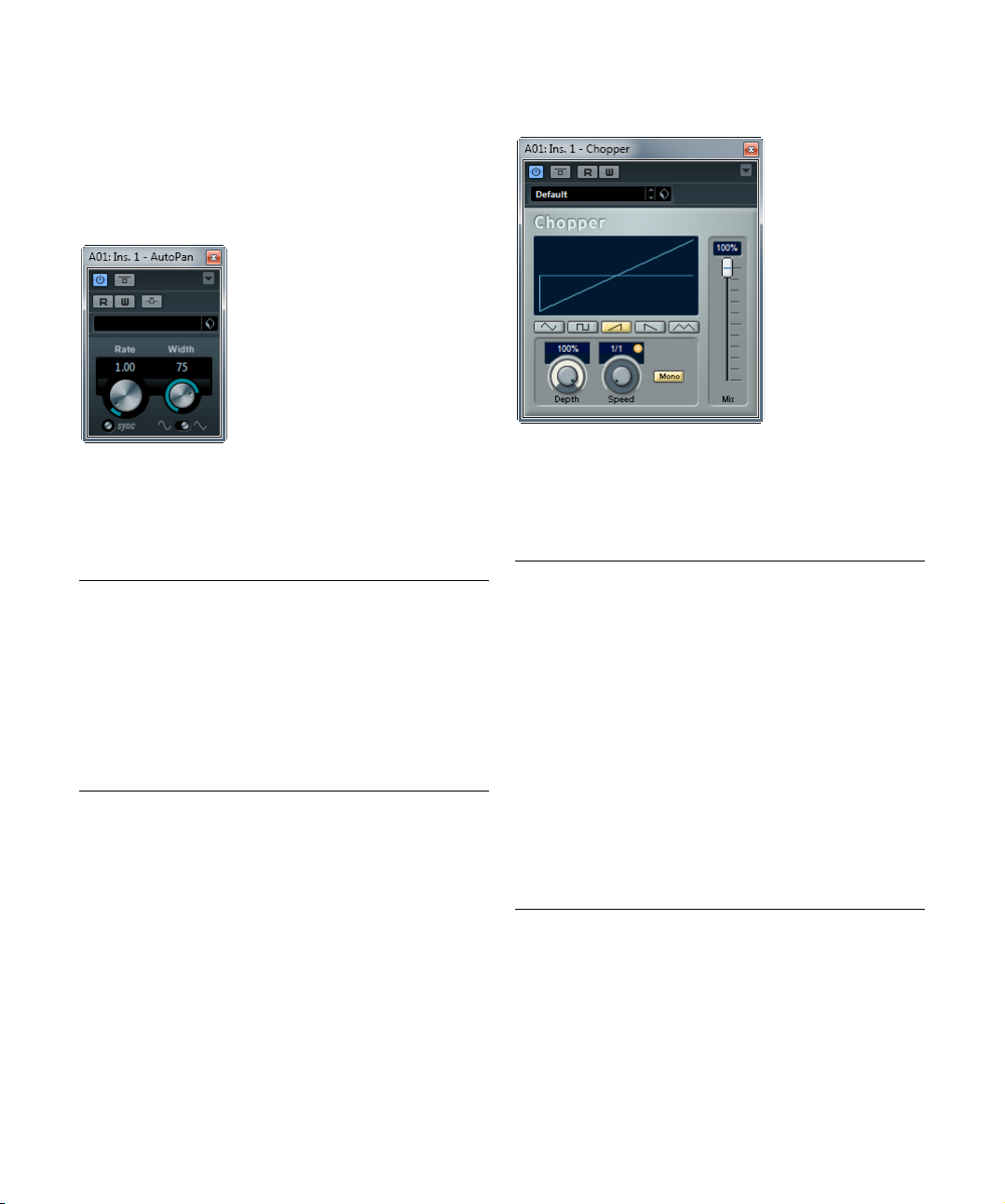
Modulation plug-ins
This section contains descriptions of the plug-ins in the
“Modulation” category.
AutoPan
This is a simple auto-pan effect. It can use different waveforms to modulate the left-right stereo position (pan), either using tempo sync or manual modulation speed
settings.
The following parameters are available:
Parameter Description
Rate If tempo sync is on, this is where you specify the base
Sync button The button below the Rate knob is used to switch tempo
Width Sets the depth of the auto-pan effect.
Waveform
Shape selector
Ö The Width parameter can also be controlled from another signal source via the side-chain input. For a description of how to set up side-chain routing, see the chapter
“Audio effects” in the Operation Manual.
note value for tempo-syncing the effect (1/1 to 1/32,
straight, triplet, or dotted).
If tempo sync is off, the auto-pan speed can be set freely
with the Rate knob.
sync on or off.
Allows you to select the modulation waveform. A sine and
a triangle waveform are available.
Chopper
Chopper is a combined tremolo and autopan effect. It can
use different waveforms to modulate the level (tremolo) or
left-right stereo position (pan), either using tempo sync or
manual modulation speed settings.
The following parameters are available:
Parameter Description
Waveform
buttons
Depth Sets the depth of the Chopper effect. This can also be
Speed If tempo sync is on, this is where you specify the base
Sync button The button above the Speed knob is used to switch
Stereo/Mono
button
Mix Sets the level balance between the dry and the wet sig-
Set the modulation waveform.
set by clicking in the graphical display.
note value for tempo-syncing the effect (1/1 to 1/32,
straight, triplet, or dotted). Note that there is no note
value modifier for this effect.
If tempo sync is off, the tremolo/auto-pan speed can be
set freely with the Speed knob.
tempo sync on (button lights up) or off.
Determines whether the Chopper works as an auto-pan-
ner (button set to “Stereo”) or a tremolo effect (button set
to “Mono”).
nal. If Chopper is used as a send effect, this should be
set to the maximum value.
The included effect plug-ins
30
Page 31

Chorus
This is a single-stage chorus effect. It works by doubling
whatever is sent into it with a slightly detuned version (see
“StudioChorus (Cubase only)” on page 35).
also
The following parameters are available:
Parameter Description
Rate If tempo sync is on, this is where you specify the base
Sync button The button below the Rate knob is used to switch tempo
Width Determines the depth of the chorus effect. Higher set-
Waveform
Shape selector
Spatial Sets the stereo width of the effect. Turn clockwise for a
Mix Sets the level balance between the dry and the wet sig-
Delay Affects the frequency range of the modulation sweep by
Filter Lo/Hi Allow you to roll off low and high frequencies of the effect
note value for tempo-syncing the chorus sweep (1/1 to
1/32, straight, triplet, or dotted).
If tempo sync is off, the sweep rate can be set freely with
the Rate knob.
sync on or off.
tings produce a more pronounced effect.
Allows you to select the modulation waveform, altering
the character of the chorus sweep. A sine and a triangle
waveform are available.
wider stereo effect.
nal. If Chorus is used as a send effect, set this to the maximum value as you can control the dry/effect balance with
the send.
adjusting the initial delay time.
signal.
Ö The modulation can also be controlled from another
signal source via the side-chain input. When the sidechain signal exceeds the threshold, the modulation is con
trolled by the side-chain signal’s envelope. For a description of how to set up side-chain routing, see the chapter
“Audio effects” in the Operation Manual.
Cloner (Cubase only)
The Cloner plug-in adds up to four detuned and delayed
voices to the signal, for rich modulation and chorus effects.
The following parameters are available:
Parameter Description
Voices Allows you to select the number of voices (up to four). For
Spatial Spreads the added voices across the stereo spectrum.
Mix Sets the level balance between the dry and the wet sig-
Output Allows you to reduce or increase the output gain by up to
Detune slider
1–4
Delay slider
1–4
Detune Governs the overall depth of the detuning for all voices. If
Natural button By clicking the Natural button below the Detune knob,
Detune –
Humanize
each added voice, a Detune and a Delay slider are added
in the right half of the panel.
Turn clockwise for a deeper stereo effect.
nal. If Cloner is used as a send effect, set this to the maximum value as you can control the dry/effect balance with
the send.
dB.
12
Controls the relative detune amount for each voice. Posi-
tive and negative values can be set, from -100 to 100. A
value of zero means no detune for that voice.
Controls the relative delay amount for each voice. A value
of zero means no delay for that voice.
this is set to zero, no detuning takes place, regardless of
the Detune slider settings.
you can change the pitch algorithm.
Controls the amount of detune variation when Static De-
tune is deactivated. With Humanize, the detune is constantly modulated for a more natural effect. The value
range is from 0 to 100 (strongest detune variation).
-
The included effect plug-ins
31
Page 32

Parameter Description
Static Detune
button
Delay Governs the overall depth of the delay for all voices. If set
Delay –
Humanize
Static Delay
button
Use this button to activate/deactivate the Static Detune
function. If activated, the set detune amount is static, and
the Humanize knob is grayed out.
to zero, no delay takes place regardless of the Delay
slider settings.
Controls the amount of delay variation when Static Detune is deactivated. With Humanize, the delay is constantly modulated for a more natural effect. The value
range is from 0 to 100 (strongest delay variation).
Use this button to activate/deactivate the Static Delay
function. If activated, the set delay amount is static, and
the Humanize knob is grayed out.
Flanger
Parameter Description
Mix Sets the level balance between the dry and the wet sig-
Waveform
Shape selector
Delay Affects the frequency range of the modulation sweep by
Manual knob Allows you to change the sweep position manually when
Manual button Use this button to activate/deactivate the Manual func-
Filter Lo/Hi Allow you to roll off low and high frequencies of the effect
nal. If Flanger is used as a send effect, set this to the maximum value as you can control the dry/effect balance with
the send.
Allows you to select the modulation waveform, altering
the character of the flanger sweep. A sine and a triangle
waveform are available.
adjusting the initial delay time.
the Manual button is deactivated. The value range is from
0 to 100.
tion. If activated, the flanger sweep is static, i. e. no modulation takes place.
signal.
Ö The modulation can also be controlled from another
signal source via the side-chain input. When the sidechain signal exceeds the threshold, the modulation is con
trolled by the side-chain signal’s envelope. For a description of how to set up side-chain routing, see the chapter
“Audio effects” in the Operation Manual.
-
Flanger is a classic flanger effect with added stereo
enhancement.
The following parameters are available:
Parameter Description
Rate If tempo sync is on, this is where you specify the base
Sync button The button below the Rate knob is used to switch tempo
Range Lo/Hi Set the frequency boundaries for the flanger sweep.
Feedback Determines the character of the flanger effect. Higher
Spatial Sets the stereo width of the effect. Turn clockwise for a
note value for tempo-syncing the flanger sweep (1/1 to
1/32, straight, triplet, or dotted).
If tempo sync is off, the sweep rate can be set freely with
the Rate knob.
sync on or off.
settings produce a more “metallic” sounding sweep.
wider stereo effect.
The included effect plug-ins
32
Page 33

Metalizer
Phaser
Metalizer feeds the audio signal through a variable frequency filter, with tempo sync or time modulation and
feedback control.
The following parameters are available:
Parameter Description
Feedback The higher the value, the more “metallic” the sound.
Sharpness Governs the character of the filter effect. The higher the
Tone Governs the feedback frequency. The effect of this will be
On button Turns filter modulation on and off. When turned off, Met-
Mono button When this is activated, the output of Metalizer is mono.
Speed If tempo sync is on, this is where you specify the base
Sync button The button above the Speed knob is used to switch
Output slider Sets the overall volume.
Mix slider Sets the level balance between the dry and the wet sig-
value, the narrower the affected frequency area, produc
ing a sharper sound and a more pronounced effect.
more noticeable with high Feedback settings.
alizer works as a static filter.
note value for tempo-syncing the effect (1/1 to 1/32,
straight, triplet, or dotted). Note that there is no note
value modifier for this effect.
If tempo sync is off, the modulation speed can be set
freely with the Speed knob.
tempo sync on (button lights up) or off.
nal. If Metalizer is used as a send effect, set this to the
maximum value as you can control the dry/effect balance
with the send.
Phaser produces the well-known “swooshing” phasing
effect with additional stereo enhancement.
The following parameters are available:
Parameter Description
Rate If tempo sync is on, this is where you specify the base
Sync button The button below the Rate knob is used to switch tempo
Width Determines the width of the modulation effect between
Feedback Determines the character of the phaser effect. Higher
Spatial When using multi-channel audio, the Spatial parameter
Mix Sets the level balance between the dry and the wet sig-
Manual knob Allows you to change the sweep position manually when
Manual button Use this button to activate/deactivate the Manual func-
Filter Lo/Hi Allow you to roll off low and high frequencies of the effect
note value for tempo-syncing the phaser sweep (1/1 to
1/32, straight, triplet, or dotted).
If tempo sync is off, the sweep rate can be set freely with
the Rate knob.
sync on or off.
higher and lower frequencies.
settings produce a more pronounced effect.
creates a 3-dimensional impression by delaying modula
tion in each channel.
nal. If Phaser is used as a send effect, set this to the maximum level as you can control the dry/effect balance with
the send.
the Manual button is deactivated. The value range is from
0 to 100.
tion. If activated, the flanger sweep is static, i. e. no modulation takes place.
signal.
-
The included effect plug-ins
33
Page 34

Ö The modulation can also be controlled from another
signal source via the side-chain input. When the sidechain signal exceeds the threshold, the modulation is con
trolled by the side-chain signal’s envelope. For a description of how to set up side-chain routing, see the chapter
“Audio effects” in the Operation Manual.
RingModulator
RingModulator can produce complex, bell-like enharmonic
sounds. Ring modulators work by multiplying two audio
signals. The ring modulated output contains added frequencies generated by the sum of, and the difference between, the frequencies of the two signals.
RingModulator has a built-in oscillator that is multiplied
with the input signal to produce the effect.
The following parameters are available:
Parameter Description
Oscillator –
LFO Amount
Oscillator –
Env. Amount
Oscillator –
Waveform
buttons
Oscillator –
Range slider
Controls how much the oscillator frequency is affected by
the LFO.
Controls how much the oscillator frequency is affected by
the envelope (which is triggered by the input signal). Pos
itive and negative values can be set, with center position
representing no modulation. Left of center, a loud input
signal will decrease the oscillator pitch, whereas right of
center the oscillator pitch will increase when fed a loud
input.
Allows you to select the oscillator waveform; square, sine,
saw, or triangle.
Determines the frequency range of the oscillator in Hz.
Parameter Description
Oscillator –
Frequency
-
Oscillator –
Roll-Off
LFO – Speed Sets the LFO speed.
LFO –
Amount
Env.
LFO –
Waveform
LFO – Invert
Stereo
Envelope
Generator
section –
Attack and
Decay
Lock L<R
button
Output slider Sets the overall volume.
Mix slider Adjusts the mix between dry and processed signal.
Sets the oscillator frequency +/- 2 octaves within the selected range.
Cuts high frequencies in the oscillator waveform, to
soften the overall sound. This is best used when harmon
ically rich waveforms are selected (e. g. square or saw).
Controls how much the input signal level – via the envelope generator – affects the LFO speed. Positive and
negative values can be set, at 0
plied. With negative values, a loud input signal slows
down the LFO, whereas positive values are used to
speed it up at loud input signals.
Allows you to select the LFO waveform; square, sine,
saw, or triangle.
Inverts the LFO waveform for the right channel of the oscillator, which produces a wider stereo perspective for
the modulation.
The Envelope Generator section controls how the input
signal is converted to envelope data, which can then be
used to control oscillator pitch and LFO speed. It has two
main controls:
Attack controls how fast the envelope output level rises in
response to a rising input signal.
Decay controls how fast the envelope output level falls in
response to a falling input signal.
When this button is enabled, the L and R input signals
are merged, and produce the same envelope output level
for both oscillator channels. When disabled, each chan
nel has its own envelope, which affects the two channels
of the oscillator independently.
% no modulation is ap-
Rotary
-
The Rotary plug-in simulates the classic effect of a rotating speaker. A rotary speaker cabinet features speakers
rotating at variable speeds to produce a swirling chorus
effect, commonly used with organs. Rotary features all the
parameters associated with the real thing.
-
-
The included effect plug-ins
34
Page 35

The following parameters are available:
Parameter Description
Speed selector (Stop/
Slow/Fast)
Speed
Change Mode
Speed Mod When the Slow/Fast setting is set to variable control, this
MIDI controller
pop-up menu
Overdrive Applies a soft overdrive or distortion.
CrossOver Sets the crossover frequency (200 to 3000 Hz) between
Horn – Slow Allows for a fine adjustment of the high rotor Slow speed.
Horn – Fast Allows for a fine adjustment of the high rotor Fast speed.
Horn – Accel. Allows for a fine adjustment of the high rotor acceleration
Horn –
Amp
Mod
Horn –
Mod
Freq
Bass – Slow Allows for a fine adjustment of the low rotor Slow speed.
Bass – Fast Allows for a fine adjustment of the low rotor Fast speed.
Bass – Accel. Allows for a fine adjustment of the low rotor acceleration
Bass –
Amp
Mod
Bass – Level Adjusts the overall bass level.
Microphones –
Phase
Microphones –
Angle
Microphones –
Distance
Output Allows you to adjust the overall output level.
Mix Allows you to adjust the mix between dry and processed
Allows you to control the speed of the Rotary in three
steps.
Allows you to select whether the Slow/Fast setting is a
switch (left) or a variable control (right). When switch
mode is selected and Pitchbend is the controller, the
speed will switch with an up or down flick of the bender.
Other controllers switch at MIDI value 64.
allows you to select the rotary speed, from 0 (Stop) to
100 (Fast).
Allows you to choose the MIDI controller that is used to
control the plug-in. Set this to “Automation” if you do not
want to use MIDI realtime control.
the low and high frequency loudspeakers.
time.
Controls the high rotor amplitude modulation.
Controls the high rotor frequency modulation.
time.
Adjusts the modulation depth of the amplitude.
Allows you to adjust the phasing amount in the sound of
the high rotor.
Sets the simulated microphone angle. 0 = mono, 180 =
one mic on each side.
Sets the simulated microphone distance from the
speaker in inches.
signals.
Directing MIDI to the Rotary
For realtime MIDI control of the Speed parameter, MIDI
must be directed to the Rotary.
• Whenever Rotary has been added as an insert effect
(for an audio track or an FX channel), it is available on the
Output Routing pop-up menu for MIDI tracks.
If Rotary is selected on the Output Routing menu, MIDI is directed to the
plug-in from the selected track.
StudioChorus (Cubase only)
The StudioChorus plug-in is a two stage chorus effect
which adds short delays to the signal and pitch modulates
the delayed signals to produce a “doubling” effect. The
two separate stages of chorus modulation are completely
independent and are processed serially (cascaded).
For each stage the following parameters are available:
Parameter Description
Rate If tempo sync is on, this is where you specify the base
Sync button The button below the Rate knob is used to switch
Width Determines the depth of the chorus effect. Higher set-
Waveform
Shape selector
Spatial Sets the stereo width of the effect. Turn clockwise for a
Mix Sets the level balance between the dry and the wet sig-
note value for tempo-syncing the chorus sweep (1/1 to
1/32, straight, triplet, or dotted).
If tempo sync is off, the sweep rate can be set freely
with the Rate knob.
tempo sync on or off.
tings produce a more pronounced effect.
Allows you to select the modulation waveform, altering
the character of the chorus sweep. A sine and a trian
gle waveform are available.
wider stereo effect.
nal. If StudioChorus is used as a send effect, set this to
the maximum value as you can control the dry/effect
balance with the send.
-
The included effect plug-ins
35
Page 36

Parameter Description
Delay Affects the frequency range of the modulation sweep
Filter Lo/Hi Allow you to roll off low and high frequencies of the ef-
by adjusting the initial delay time.
fect signal.
Ö The modulation can also be controlled from another
signal source via the side-chain input. When the sidechain signal exceeds the threshold, the modulation is controlled by the side-chain signal’s envelope. For a description of how to set up side-chain routing, see the chapter
“Audio effects” in the Operation Manual.
Parameter Description
Sync button The button above the Speed knob is used to switch
On button Turns modulation of the pitch parameter on or off.
Mono button Governs whether the output is stereo or mono.
Output slider Allows you to adjust the output level of the effect.
Mix slider Sets the level balance between the dry and the wet sig-
tempo sync on (button lights up) or off.
nal.
Ö Note that clicking and dragging in the display allows
you to adjust the Tone and Depth parameters at the same
time!
Tranceformer
Tranceformer is a ring modulator effect, in which the incoming audio is ring modulated by an internal, variable frequency oscillator, producing new harmonics. A second
oscillator can be used to modulate the frequency of the
first oscillator, in sync with the Song tempo if needed.
The following parameters are available:
Parameter Description
Waveform
buttons
Tone Sets the frequency (pitch) of the modulating oscillator
Depth Governs the depth of the pitch modulation.
Speed If tempo sync is on, this is where you specify the base
Allow you to select a pitch modulation waveform.
to 5000 Hz).
(1
note value for tempo-syncing the effect (1/1 to 1/32,
straight, triplet, or dotted). Note that there is no note
value modifier for this effect.
If tempo sync is off, the modulation speed can be set
freely with the Speed knob.
Tremolo
Tremolo produces amplitude (volume) modulation. The
following parameters are available:
Parameter Description
Rate If tempo sync is on, this is where you specify the base
Sync button The button below the Rate knob is used to switch tempo
Depth Governs the depth of the amplitude modulation.
Spatial Adds a stereo effect to the modulation.
Output Allows you to adjust the output volume.
Ö The modulation can also be controlled from another
signal source via the side-chain input. When the sidechain signal exceeds the threshold, the modulation is con
trolled by the side-chain signal’s envelope. For a description of how to set up side-chain routing, see the chapter
“Audio effects” in the Operation Manual.
note value for tempo-syncing the effect (1/1 to 1/32,
straight, triplet, or dotted).
If tempo sync is off, the modulation speed can be set
freely with the Rate knob.
sync on or off.
-
The included effect plug-ins
36
Page 37

Vibrato
The Vibrato plug-in produces pitch modulation. The following parameters are available:
Parameter Description
Rate If tempo sync is on, this is where you specify the base
Sync button The button below the Rate knob is used to switch tempo
Depth Governs the depth of the pitch modulation.
Spatial Adds a stereo effect to the modulation.
Ö The modulation can also be controlled from another
signal source via the side-chain input. When the sidechain signal exceeds the threshold, the modulation is con
trolled by the side-chain signal’s envelope. For a description of how to set up side-chain routing, see the chapter
“Audio effects” in the Operation Manual.
note value for tempo-syncing the effect (1/1 to 1/32,
straight, triplet, or dotted).
If tempo sync is off, the modulation speed can be set
freely with the Rate knob.
sync on or off.
Pitch Shift plug-ins
This section contains descriptions of the plug-ins in the
“Pitch Shift” category.
Octaver
This plug-in can generate two additional voices that track
the pitch of the input signal one octave and two octaves
below the original pitch, respectively. Octaver is best used
with monophonic signals.
The following parameters are available:
Parameter Description
Direct Adjusts the mix of the original signal and the generated
Octave 1 Adjusts the level of the signal that is generated one oc-
-
Octave 2 Adjusts the level of the signal that is generated two oc-
voices. A value of 0 means only the generated and trans
posed signal is heard. By raising this value, more of the
original signal is heard.
tave below the original pitch. A setting of 0 means that
the voice is muted.
taves below the original pitch. A setting of 0 means that
the voice is muted.
-
The included effect plug-ins
37
Page 38

Pitch Correct
Pitch Correct automatically detects, adjusts and fixes
slight pitch and intonation inconsistencies in monophonic
vocal and instrumental performances in realtime. The ad
vanced algorithms of this plug-in preserve the formants of
the original sound thus allowing for natural sounding pitch
correction without the typical “Mickey Mouse” effect.
Furthermore, you can use Pitch Correct creatively. You
can create backing vocals, for example, by modifying the
lead vocals or vocoder sounds by using extreme values.
You can use an external MIDI controller, a MIDI track or
the virtual keyboard to “play” a note or a scale of target
pitches that determine the current scale notes to which
the audio is shifted. This allows you to change your audio
in a very quick and easy way, which is extremely useful for
live performances. In the keyboard display, the original au
dio will be displayed in blue while the changes are displayed in orange.
The following parameters are available:
Parameter Description
Correction –
Speed
Correction –
Tolerance
Correction –
Transpose
(-12 to 12)
Determines the smoothness of the pitch change. Higher
values cause the pitch shift to occur immediately. 100 is
a very drastic setting that is designed mainly for special
effects (e.
g. the famous “Cher” effect).
Determines the sensitivity of analysis. A low Tolerance
value lets Pitch Correct find pitch changes quickly.
When the Tolerance value is high, pitch variations in the
audio (e.
g. vibrato) will not be immediately interpreted as
note changes.
With this parameter you can adjust (or “retune”) the pitch
of the incoming audio in semitone steps. You can set
positive and negative values from -12 to 12. A value of
zero means that the signal is not transposed.
-
Parameter Description
Scale Source –
Internal
Scale Source –
External MIDI
Scale
Scale Source –
External MIDI
Note
Formant – Shift
(-60 to 60)
Formant –
Optimize (Gen
eral, Male, Female)
Formant –
Preservation
(On/Off)
-
Master Tuning Detunes the output signal. The default setting is 440 Hz.
If you choose the Internal option from the Scale Source
pop-up menu, you can use the pop-up menu next to it to
decide to which scale the source audio will be adapted.
The following options are available:
Chromatic: The audio will be pitched to the closest semitone.
Major/Minor: The audio will be pitched to the major/minor scale specified in the pop-up menu to the right. This
will be reflected on the keyboard display.
Custom: The audio will be pitched to the notes that you
specify by clicking the desired keys on keyboard display.
To reset the keyboard, click on the orange line below the
display.
Select this option if you want the audio to be shifted to a
scale of target pitches, using an external MIDI controller,
the Virtual Keyboard or a MIDI track.
Note that you have to assign the audio track as the output of your MIDI track and that the Speed parameter has
to be set to a value other than Off.
Select this option if you want the audio to be shifted to a
target note, using an external MIDI controller, the Virtual
Keyboard or a MIDI track.
Note that you have to assign the audio track as the output of your MIDI track and that the Speed parameter has
to be set to a value other than Off.
Changes the natural timbre, i. e. the characteristic frequency components of the source audio.
Allows you to specify the sound characteristics of the
sound sources. While General is the default setting,
Male is designed for low pitches and Female for high
pitches.
When set to Off, formants are raised and lowered with
the pitch, provoking strange vocal effects. Higher pitch
correction values result in “Mickey Mouse” effects, lower
pitch correction values in “Monster” sounds.
When set to On, the formants are kept, maintaining the
character of the audio.
The included effect plug-ins
38
Page 39

Reverb plug-ins
This section contains descriptions of the plug-ins in the
“Reverb” category.
REVerence (Cubase only)
REVerence is a convolution tool that allows you to apply
room characteristics (reverb) to the audio. This is done by
processing the audio signal according to an impulse response – a recording of an impulse in a room or another
location that is used to recreate the characteristics of the
room. As a result, the processed audio will sound as if it
were played in the same location. Included with the plugin are top quality samples of real spaces to create rever
beration.
Ö REVerence can be very demanding in terms of RAM.
This is because the impulse responses that you load into
the program slots are preloaded into RAM to guarantee an
artifact-free switching between programs. Therefore you
should always load only those programs that you need for
a given task.
Using the program matrix
A program is the combination of an impulse response and
its settings. These include reverb settings (see
the reverb settings” on page 40), EQ settings (see “Making EQ settings” on page 41), pictures (see “Loading pic-
tures” on page 42), and output settings (see “Making
“Changing
-
output settings” on page 42). The program matrix allows
you to load programs and to view the name of the current
program, i.
e. the impulse response (see “Working with
custom impulse responses” on page 42).
The following parameters are available:
Parameter Description
Program name In the upper left corner of the plug-in panel, either the
Browse button This button opens a browser window showing the avail-
Import button Click this button to load your own impulse response files
Program slots
(1 to 36)
Smooth
Parameter
Changes
button
Store button Stores the active impulse response and its settings as a
Recall button Reloads the selected program. Use this to reset a pro-
Erase button Removes the selected program from the matrix.
name of the loaded impulse response file or the name of
the program is shown. After loading an impulse response,
its number of channels and the length in seconds are dis
played for a few seconds.
able programs. When you select a program in the
browser, it is loaded into the active program slot. To be
able to filter the list of impulse responses in the browser
window, e.
you can activate the Filters section (by clicking the “Set
Up Window Layout” button at the bottom left of the win
dow).
from disk. The files should have a maximum length of 10
seconds. Longer files are automatically cut. For more infor
mation, see “Working with custom impulse responses” on
page 42.
Into these slots you can load all the impulse responses
(programs) that you want to work with in a session. The
selected program slot is indicated by a (blinking) white
frame. Occupied slots are shown in a different color.
Double-clicking an empty program opens a browser win
dow, showing the available programs. Double-clicking an
occupied program slot loads the corresponding impulse
response into REVerence (“Recall”).
The “Smooth Parameter Changes” button is located between the program slots and the Store/Recall/Erase buttons. If it is activated, a crossfade is performed when
switching programs.
Leave this button deactivated while looking for a suitable
program or an appropriate setting for an impulse re
sponse. Once you have set up the program matrix to your
liking, activate the button to avoid hearing artifacts when
switching between programs.
program.
gram to its default settings.
g. by room type or the number of channels,
-
-
-
-
-
The included effect plug-ins
39
Page 40

Programs vs. presets
Δ
You can save your REVerence settings as VST plug-in
presets or programs. The differences between the two
and the advantages are described in the following.
Both presets and programs use the file extension .vstpreset and appear in the same category in the MediaBay
(Plug-In Presets), but they are represented by different
icons:
Icon Description
A REVerence preset contains all settings and parameters for
the plug-in, that is all the loaded impulse responses along
with their parameter settings and positions in the program
matrix. Presets are loaded via the Presets pop-up menu at
the top of the plug-in panel.
A REVerence program only contains the settings related to a
single impulse response. Programs are loaded and managed
via the program matrix.
Presets
Presets are useful in the following situations:
• When you want to save a complete setup with different
impulse responses for later use (e. g. different setups for
explosion sounds that can be reused for other scenes or
movies).
• When you want to save different parameter sets for the
same impulse response so that you can later choose the
set that best suits your needs.
Programs
Programs offer the following advantages:
• Up to 36 programs can be loaded into the program matrix for instant recall.
• A program provides a quick and easy way to save and
recall a subset of the plug-in parameters (i.
for a single impulse response), allowing for short loading
times.
• When automating a project and loading a REVerence
program, only two automation events are written.
If load a plug-in preset instead (which contains a lot more settings than a
program), a lot of unnecessary automation data (for the settings that you
did not use) is written.
e. the settings
Setting up programs
Proceed as follows:
1. In the program matrix, click on a program slot to select
it.
A blinking white frame indicates that this program slot is selected.
2. Click the Browse button or click on the empty slot
again to load one of the included programs.
You can also import a new impulse response file, see “Importing impulse
responses” on page 42.
3. In the browser that appears, select the program containing the impulse response that you want to use and
click OK.
The name of the loaded impulse response is shown in the upper left corner of the REVerence panel.
4. Set up the REVerence parameters as needed and
click the Store button to save the impulse response with
the current settings as a new program.
5. Set up as many programs as you need (up to 36) by
following the steps above.
Ö If you want to use your set of programs in other projects, save your settings as a plug-in preset using the Presets pop-up menu at the top of the plug-in panel.
Changing the reverb settings
The reverb settings allow you to change the characteristics of the room.
The following parameters are available:
Parameter Description
Front All values shown in the top row are for the front speakers.
Rear
Auto Gain
button
Reverse button Reverses the impulse response.
Pre-Delay Controls the amount of time between the dry signal and
Time Scaling Controls the reverb time.
Size Determines the size of the simulated room.
If you are working with surround tracks up to 5.1, you can
use this row to set up an offset for the rear channels.
When this button is activated, the impulse response is
automatically normalized.
the onset of the reverb. With higher pre-delay values you
can simulate larger rooms.
The included effect plug-ins
40
Page 41

Parameter Description
Level A level control for the impulse response. This governs the
ER Tail Split Sets a split point between the early reflections and the
ER Tail Mix Allows you to set up the relation of early reflections and
volume of the reverb.
tail, allowing you to determine where the reverb tail be
gins. A value of 60 means that the early reflections will be
heard for 60
tail. Values above 50 attenuate the early reflections and
values below 50 attenuate the tail.
ms.
-
The impulse response display
The Display section allows you to view the impulse response details and to change the length of the response
(trimming).
The following parameters are available:
Parameter Description
Play button/
Time Scaling
wheel
Time Domain
display
Spectrogram
display
Information
display
Activate
Impulse
Trimming
button
Trim slider Allows you to trim the start and end of the impulse re-
When clicking the play button to apply the loaded impulse
response, a short click is played. This provides a neutral
test sound that makes it easier for you to know how differ
ent settings influence the reverb characteristics.
The Time Scaling wheel lets you adjust the reverb time.
Shows the waveform of the impulse response.
Shows the analyzed spectrum of the impulse response.
Time is displayed along the horizontal axis, frequency
along the vertical axis, and volume is represented by the
color.
Shows additional information, e. g. the name of the program and the loaded impulse response, the number of
channels, the length, and Broadcast Wave File informa
tion.
Use this button at the bottom right of the Impulse display
section to activate impulse trimming. The Trim slider is
shown below the Impulse display.
sponse. Drag the front handle to trim the start of the impulse response, or the end handle to trim the reverb tail.
You can also use the mouse wheel for trimming. Note that
the impulse response will be cut without any fading.
Making EQ settings
In the Equalizer section you can tune the sound of the
reverb.
The following parameters are available:
Parameter Description
EQ curve display Shows the EQ curve. You can use the EQ parameters
Activate EQ
button
Low Shelf On
button
Low Freq
(20 to 500)
-
Low Gain
(-24 to +24)
Mid Peak On
button
Mid Freq
(100 to 10000)
Mid Gain
(-12 to +12)
Hi Shelf On
button
Hi Freq
(5000 to 20000)
Hi Gain
(-24 to +24)
below the display to change the EQ curve, or modify the
curve manually by dragging the curve points.
This button to the right of the EQ parameters activates
the EQ for the effect plug-in.
Activates the low shelf filter that boosts or cuts frequencies below the cutoff frequency by the specified
amount.
Sets the frequency of the low band.
Sets the amount of cut/boost for the low band.
Activates the mid peak filter that creates a peak or
notch in the frequency response.
Sets the center frequency of the mid band.
Sets the amount of cut/boost for the mid band.
Activates the high shelf filter that boosts or cuts frequencies above the cutoff frequency by the specified
amount.
Sets the frequency of the high band.
Sets the amount of cut/boost for the high band.
The included effect plug-ins
41
Page 42

Loading pictures
In the Pictures section you can load graphics files to illustrate the setting, i. e. the recording location or microphone
arrangement of the loaded impulse response. Up to five
pictures can be loaded.
The following parameters are available:
Parameter Description
Output activity
meter
Output slider Allows you to adjust the overall output level.
Out
(-24 to +12)
Mix
(0 to 100)
Indicates the overall level of the impulse response and its
settings.
Raises or lowers the signal output of the plug-in.
Sets the level balance between the dry and the wet
signal.
• To lock the dry/wet balance while browsing through the
available presets and programs, activate the Lock button
(padlock symbol) next to the MIX parameter.
The following parameters are available:
Parameter Description
Add button Opens a file dialog where you can navigate to the graph-
Next button If several pictures are loaded, you can click this button to
Remove button Deletes the active picture. Note that this will not remove
ics file that you want to import. JPG, GIF, and PNG file
formats are supported.
display the next image.
the graphics file from your hard disk.
Ö Pictures are only referenced by the plug-in and will not
be copied to the project folder.
Making output settings
In the Output section you can control the overall level and
determine the dry/wet mix.
Working with custom impulse responses
In addition to working with the impulse responses included
with REVerence, you can import your own impulse responses and save these as programs or presets. WAVE
and AIFF files with a mono, stereo, true-stereo, or multichannel (up to 5.0) configuration are supported. If a multichannel file contains an LFE channel, this channel is
ignored.
REVerence uses the same channel width as the track it is
inserted on. When importing impulse response files with
more channels than the corresponding track, the plug-in
only reads as many channels as needed. If the impulse re
sponse file contains less channels than the track, REVerence generates the missings channels (e. g. the center
channel as a sum of the left and right channels). If the rear
channels are missing (when importing a stereo response
file onto a 4.0 track, for example), the left and right chan
nels are also used for the rear channels. In this case you
can use the Rear offset parameter to create more spatiality.
Importing impulse responses
To import impulse responses, proceed as follows:
1. In the program matrix, click the Import button.
2. Navigate to the file that you want to import, and click
Open.
The file is loaded into REVerence. The channels from an interleaved file
are imported in the same order as in other areas of Cubase (e.
Connections window), see below.
-
g. the VST
-
The included effect plug-ins
42
Page 43

3. Make the appropriate settings and add a picture, if
available.
Pictures residing in the same folder as the impulse response file or in the
parent folder are automatically found and displayed.
4. Click the Store button to save the impulse response
and its settings as a program. That way you can recall the
setup at any time.
The program slot turns blue, indicating that a program is loaded.
Ö When saving a program, the impulse response file itself is only referenced. It still resides in the same location
as before and is not modified in any way.
5. Repeat these steps for any impulse response files that
you want to work with.
REVerence reads input channels in the following order:
No. of input
channels
1 L
2 L/R
3 L/R/C
4 L/R/LS/RS (if inserted on a track with a 4.0 channel con-
4 LL/LR/RL/RR (if inserted on a track with a stereo config-
5 L/R/C/LS/RS
6 L/R/C/LFE/LS/RS (LFE is being ignored.)
Channel order in REVerence
figuration, see below)
uration, see below)
True stereo
Impulse responses recorded as trues-stereo files enable
you to create a very realistic impression of the corre
sponding room. REVerence can only process true-stereo
impulse response files with the following channel configu
ration (in exactly that order): LL, LR, RL, RR.
The channels are defined as follows:
Channel The signal from this
LL left source left microphone
LR left source right microphone
RL right source left microphone
RR right source right microphone
source…
…was recorded with this
microphone
Ö If your true-stereo impulse responses are only available as separate mono files, you can use the Export Audio
Mixdown function in Cubase to create REVerence compli
ant interleaved files (see the chapter “Export Audio Mixdown” in the Operation Manual).
By default, REVerence automatically works in true-stereo
mode when the plug-in is inserted on a stereo track and
you load a 4-channel impulse response.
Therefore, if you are working with surround files, that is,
4-channel impulse responses recorded with a Quadro
configuration (L/R, LS/RS), you need to insert the plug-in
on an audio track with a 4.0 configuration. On a stereo
track these files would be processed in true-stereo mode,
too.
So how can you prevent REVerence from unintentionally
processing surround files in true-stereo mode? The answer is a “Recording Method” attribute that can be written
to the iXML chunk of the corresponding impulse response
file. Whenever you load an impulse response with a
4-channel configuration on a stereo track, REVerence
searches the iXML chunk of the file. If the plug-in finds the
Recording Method attribute, the following happens:
• If the attribute is set to “TrueStereo”, the plug-in works
in true-stereo mode.
• If the attribute is set to “A/B” or “Quadro”, the plug-in
works in normal stereo mode and processes only the L/R
channels of the surround file.
Ö You can use the Attribute Inspector in the MediaBay
to tag your own impulse response files with the Recording
Method attribute. For more information, see the chapter
“MediaBay” in the Operation Manual.
-
Relocating content
Once you have imported your own impulse responses in
REVerence you can comfortably work with them on your
computer. But what if you need to transfer your content to
another computer, for example because you work some
times with a PC and sometimes with a notebook, or you
need to hand over a project to a colleague in the studio?
The factory content will not be a problem since it is also
present on the other computer. For these impulse re
sponses you just need to transfer your REVerence programs and presets to be able to access your setups.
-
-
-
The included effect plug-ins
43
Page 44

User content is a different matter, though. If you have
!
transferred your audio files to an external drive or a different hard disk location on the other computer, REVerence
cannot access the impulse responses any more since the
old file paths have become invalid.
To access your impulse responses again, proceed as follows:
1. Transfer you audio files to a location that you will be
able to access from the second computer (i. e. an external
hard disk).
If you keep the files in the same folder structure as on the first computer,
REVerence will automatically find all files contained in this structure.
2. Transfer any REVerence presets or programs that you
need to the second computer.
If you are unsure where the presets need to be stored, you can find the
paths in the MediaBay (see the chapter “The MediaBay” in the Operation
Manual).
3. Open REVerence on the second computer and try to
load the preset or program that you want to work with.
The Locate Impulse Response dialog opens.
4. Navigate to the folder that contains your impulse responses. Click Open.
REVerence is now able to access all the impulse responses stored in this
location.
The new path to these audio files has not been saved
yet. To make the files permanently available without
having to use the Locate dialog, you need to save
your programs or presets under a different name.
RoomWorks (Cubase only)
RoomWorks is a highly adjustable reverb plug-in for creating realistic room ambience and reverb effects in stereo
and surround formats. The CPU usage is adjustable to fit
the needs of any system. From short room reflections to
cavern-sized reverb, this plug-in delivers high quality re
verberation.
-
The following parameters are available:
Parameter Description
Input – Lo Freq Determines the frequency at which the low-shelving filter
Input – Hi Freq Determines the frequency at which the high-shelving filter
Input –
Lo
Gain
Input – Hi Gain Controls the amount of boost or cut for the high-shelving
Reverb –
Pre-Delay
Reverb –
Reverb Time
Reverb – Size Alters the delay times of early reflections to simulate
Reverb –
Diffusion
Reverb –
Width
Reverb –
Variation
button
Reverb – Hold
button
Damping –
Freq
Lo
Damping –
High Freq
Damping –
Low Level
Damping –
High Level
Envelope –
Amount
takes effect. Both the high and low settings filter the input
signal prior to reverb processing.
takes effect. Both the high and low settings filter the input
signal prior to reverb processing.
Controls the amount of boost or cut for the low-shelving
filter.
filter.
Controls how much time passes before the reverb is ap-
plied. This allows you to simulate larger spaces by increasing the time it takes for first reflections to reach the
listener.
Allows you to set the reverb time in seconds.
larger or smaller spaces.
Affects the character of the reverb tail. Higher values lead
to more diffusion and a smoother sound, while lower val
ues lead to a clearer sound.
Controls the width of the stereo image. 100 % gives you
full stereo reverb. At 0
Pressing this button generates a new version of the same
reverb program using altered reflection patterns. This is
helpful when certain sounds are causing odd ringing or
undesirable results. Creating a new variation will often
solve these issues. There are 1000 possible variations.
Pressing this button freezes the reverb buffer in an infinite
loop (yellow circle around button). You can create some
interesting pad sounds using this feature.
Determines the frequency below which low-frequency
damping will occur.
Determines the frequency above which high-frequency
damping will occur.
Affects the decay time of low frequencies. Normal room
reverb decays quicker in the high- and low-frequency
range than in the mid-range. Lowering the level percent
age causes low frequencies to decay quicker. Values
above 100
slowly than the mid-range frequencies.
Affects the decay time of high frequencies. Normal room
reverb decays quicker in the high- and low-frequency
range than in the mid-range. Lowering the level percent
age causes high frequencies to decay quicker. Values
above 100
slowly than the mid-range frequencies.
Determines how much the envelope attack and release
controls affect the reverb itself. Lower values have a more
subtle effect while higher values lead to a more drastic
sound.
% cause low frequencies to decay more
% cause high frequencies to decay more
%, the reverb is all in mono.
-
-
-
The included effect plug-ins
44
Page 45

Parameter Description
Envelope –
Attack
Envelope –
Release
Surround –
Distance
Surround –
Rotate button
Surround –
Balance
Output – Mix Determines the balance of dry (unprocessed) and wet
Output –
Wet
only
button
Output –
Efficiency
Output –
Export button
Output –
Output meter
The envelope settings in RoomWorks control how the reverb will follow the dynamics of the input signal in a fashion similar to a noise gate or downward expander. Attack
determines how long it takes for the reverb to reach full
volume after a signal peak (in milliseconds). This is similar
to a pre-delay but the reverb is ramping up instead of
starting all at once.
Determines how long after a signal peak the reverb can
be heard before being cut off, similar to a gate’s release
time.
This control is only available for surround configurations.
With this parameter you can control where the virtual lis
tening position is within the room. Positive values position
the listener closer to the front of the room and negative
values place the listener towards the rear of the room.
This button is only available for surround configurations.
When active, the perspective of the room is shifted 90°.
This control is only available for surround configurations.
Balance controls the relative levels between the forward
and rear speakers. Positive values favor the front speak
ers and negative values favor the rear speakers. When
the Rotate option is activated, these relationships will
shift 90°.
(processed) signal. When RoomWorks is used as an in
sert for an FX channel, you will most likely want to set this
to 100
% or use the wet only button.
This button defeats the mix parameter, setting the effect
% wet or affected signal. This button should nor-
to 100
mally be pressed when RoomWorks is being used as a
send effect for an FX or group channel.
Determines how much processing power is used for
RoomWorks. The lower the value, the more CPU re
sources will be used, and the higher the quality of the reverb. Interesting effects can be created with very high
Efficiency settings (>90
Determines if during audio export RoomWorks will use
the maximum CPU power for the highest quality reverb.
During export you may wish to keep a higher efficiency
setting to achieve a specific effect. If you want the high
est quality reverb during export, make sure this button is
activated.
Indicates the level of the output signal.
%). Experiment for yourself.
-
RoomWorks SE
-
RoomWorks SE is a “lite” version of the RoomWorks plugin. This plug-in delivers high quality reverberation, but has
fewer parameters and is less CPU demanding than the full
version.
The following parameters are available:
Parameter Description
Pre-Delay Controls how much time passes before the reverb is ap-
-
Reverb Time Allows you to set the reverb time in seconds.
Diffusion Affects the character of the reverb tail. Higher values lead
Hi Level Affects the decay time of high frequencies. Normal room
Lo Level Affects the decay time of low frequencies. Normal room
Mix Determines the blend of dry (unprocessed) signal to wet
plied. This allows you to simulate larger spaces by increasing the time it takes for first reflections to reach the
listener.
to more diffusion and a smoother sound, while lower val
ues lead to a clearer sound.
reverb decays quicker in the high- and low-frequency
range than in the mid-range. Lowering the level percent
age causes high frequencies to decay quicker. Values
above 100
slowly than the mid-range frequencies.
reverb decays quicker in the high- and low-frequency
range than in the mid-range. Lowering the level percent
age causes low frequencies to decay quicker. Values
above 100
slowly than the mid-range frequencies.
(processed) signal. When using RoomWorks SE inserted
in an FX channel, you will most likely want to set this to
100
% cause high frequencies to decay more
% cause low frequencies to decay more
%.
-
-
-
The included effect plug-ins
45
Page 46

Spatial + Panner plug-ins
This section contains descriptions of the plug-ins in the
“Spatial + Panner” category.
MonoToStereo
This effect will turn a mono signal into a “pseudo-stereo”
signal. The plug-in must be inserted on a stereo track
playing a mono file.
The following parameters are available:
Parameter Description
Width Controls the width or depth of the stereo enhancement.
Delay Increases the amount of differences between the left and
Color Generates additional differences between the channels
Mono button Switches the output to mono, to check for possible un-
Turn clockwise to increase the enhancement.
right channels to further increase the stereo effect.
to increase the stereo effect.
wanted coloring of the sound which sometimes can occur when creating an artificial stereo image.
StereoEnhancer
This plug-in will expand the stereo width of (stereo) audio
material. It cannot be used with mono files.
The following parameters are available:
Parameter Description
Width Controls the width or depth of the stereo enhancement.
Delay Increases the amount of differences between the left and
Color Generates additional differences between the channels
Mono button Switches the output to mono, to check for possible un-
Turn clockwise to increase the enhancement.
right channels to further increase the stereo effect.
to increase the stereo enhancement.
wanted coloring of the sound which sometimes can occur when enhancing the stereo image.
The included effect plug-ins
46
Page 47

Surround plug-ins (Cubase only)
This section describes the plug-ins in the “Surround”
category.
Mix6To2
Mix6To2 lets you quickly mix down your surround mix format to stereo. You can control the levels of up to six surround channels and decide for each channel up to which
level it will be included in the resulting mix.
Ö Mix6To2 does not simulate a surround mix or add any
psycho-acoustical artifacts to the resulting output – it is
simply a mixer. The plug-in should be placed in one of the
post-fader insert effect slots for the output bus.
For each of the surround channels the following parameters are available:
• Two volume faders that govern how much of the signal will be
included in the left and/or right channel of the output bus.
• A Link button that links the two volume faders.
• Two Invert buttons that allow you to invert the phase of the left
and right channel of the surround bus.
For the Output bus the following parameters are available:
• A Link button that links the two Output faders.
• A Normalize button. If activated, the mixed output is normalized, i. e. the output level is automatically adjusted so that the
loudest signal is as loud as possible without clipping.
MixerDelay
MixerDelay allows you to adjust and manipulate each individual channel in a surround track, group or bus.
• Above the individual channel controls you will find
global buttons for turning off Mute, Solo and Invert Phase
switches for all channels.
For each channel the following controls are available:
Parameter Description
Mute button Allows you to mute individual channels.
Solo button Allows you to solo individual channels.
Inv button Lets you invert the phase or polarity for individual chan-
Delay slider Allows you to delay individual speaker channels. The de-
Level slider Allows you to fine-tune the volume balance between the
Volume meter Shows the level of the input signal.
Routing
section
Ö It is common for the center channel in a 5.1 speaker
configuration to be closer to the mix position in order to
accommodate large video monitors or projection screens.
In cases like this, MixerDelay can be used to compensate
for the center channel being too close. Simply adjust the
delay for the center channel by the difference in distance
(in cm) between it and the other speakers to the mix posi
tion. You must delay the closer speaker so that the sound
from it arrives at the same time as the sound from the more
nels.
lay times are shown in milliseconds and centimeters,
making this feature very useful for distance compensation
when playing back surround mixes on different speaker
setups, etc.
surround channels.
Lets you select/switch the desired outputs for the channels quickly. You can assign the same output to several
channels by holding down the [Alt]/[Option] key while se
lecting. Note that there are also several channel routing
presets available.
-
-
The included effect plug-ins
47
Page 48

distant speakers. Note that MixerDelay has a wide range
!
(up to 1000 ms) and fine adjustments are best made by
numerically entering the delay time in centimeters for
speaker alignment.
The MixerDelay is not a mixer – the number of outputs is the same as the number of inputs. If you need
to mix down a surround signal to stereo, use the
Mix6to2, Mix8to2 or MixConvert plug-ins.
Tools plug-ins
This section describes the plug-ins in the “Tools” category.
MultiScope (Cubase only)
MultiScope can be used for viewing the waveform, phase
linearity or frequency content of a signal. There are three
different modes:
• Oscilloscope (Ampl.)
• Phase Correlator (Scope)
• Frequency Spectrum Analyzer (Freq.)
Ö The Freeze button can be used to freeze the display in
all three modes. Click it again to exit freeze mode.
Oscilloscope mode (Ampl.)
• To view a signal waveform, open the MultiScope control
panel and make sure that the “Ampl.” button in the lower
left corner is lit.
• If the source signal is stereo you can now select either
the Left or Right channel for viewing, or Stereo for both
channels to be shown in the window. If it is a mono signal,
this does not matter.
• If MultiScope is used with a multi-channel track or output bus, you can select any speaker channel for viewing,
or All Channels to view them all at once.
• You can now adjust the Amplitude knob to increase/
decrease the vertical size of the waveform, and the Fre
-
quency knob to select the frequency area for viewing.
Frequency Spectrum Analyzer mode (Freq.)
• Click the Freq button so that it lights up.
MultiScope now divides the frequency spectrum into separate vertical
bands, which allows you to get a visual overview of the different frequen
cies’ relative amplitude. The frequency bands are shown left to right,
starting with the lower frequencies.
-
• If the source signal is stereo you can now select either
the Left or Right channel for viewing, or Stereo for both
channels to be shown in the window. If it is a mono signal,
this does not matter.
• If MultiScope is used with a multi-channel track or output bus, you can select any speaker channel for viewing,
or All Channels to view them all at once.
• Adjust the Amplitude knob to increase/decrease the
vertical range of the bands.
The included effect plug-ins
48
Page 49

• By adjusting the Frequency knob, you can divide the
frequency spectrum into 8, 15, or 31 bands, or you set it
to “Spectrum”, which gives you a high-resolution view.
• Use the Mode A and Mode B buttons to switch be-
tween different view modes.
Mode A is more graphically detailed, showing a solid, blue amplitude bar
for each band. Mode B is less detailed, showing a continuous blue line
that displays the peak levels for each band. These view modes do not
have any effect if you have set the Frequency knob to “Spectrum”.
When MultiScope is used with a surround channel in
Scope mode, the pop-up menu to the right of the Scope
button determines the result:
• If “Stereo (Front)” is selected, the display will indicate
the phase and amplitude relationship between the front
stereo channels.
• If “Surround” is selected, the display indicates the
energy distribution in the surround field.
Phase Correlator mode (Scope)
• Click the Scope button so that it lights up.
The phase correlator indicates the phase and amplitude relationship between channels in a stereo pair or a surround configuration.
For stereo pairs, the indications work in the following way:
• A vertical line indicates a perfect mono signal (the left and
right channels are the same).
• A horizontal line indicates that the left channel is the same as
the right, but with an inverse phase.
• A random but fairly round shape indicates a well balanced stereo signal. If the shape “leans” to the left, there is more energy
in the left channel and vice versa (the extreme case of this is if
one side is muted, in which case the phase meter will show a
straight line, angled 90° to the other side).
• A perfect circle indicates a sine wave on one channel, and the
same sine wave shifted by 90° on the other.
• Generally, the more you can see a “thread”, the more bass in
the signal, and the more “spray-like” the display, the more high
frequencies in the signal.
SMPTEGenerator (Cubase only)
This plug-in is not a real audio effect. It sends out SMPTE
timecode to an audio output, allowing you to synchronize
other equipment to Cubase (provided that the equipment
can sync directly to SMPTE timecode). This can be very
useful if you do not have access to a MIDI-to-timecode
converter.
The following parameters are available:
Parameter Description
Main timecode
display
Frame rate
display and
pop-up menu
This display shows the current timecode.
When “Link to Transport” is deactivated, the generator is
in “free run” mode. You can then use the timecode dis
play to set the SMPTE start time.
When “Link to Transport” is activated, you cannot change
any of the values. This display shows the current time
code in sync with the Transport panel. Where applicable,
the offset defined in the offset timecode display is taken
into account (see below).
The frame rate shown to the right of the timecode display
defaults to the frame rate set in the Project Setup dialog.
To generate timecode in a different frame rate (e.
stripe a tape), select another format on the pop-up menu
(only available if “Link to Transport” is deactivated).
Note that for another device to synchronize correctly to
Cubase, the same frame rate has to be set in the Project
Setup dialog, the SMPTE Generator and the receiving
device.
-
-
g. to
The included effect plug-ins
49
Page 50

Parameter Description
Offset
timecode
display
Generate
Code button
Link to
Transport
button
Timecode in
Still Mode
button
This display is only available if “Link to Transport” is activated. It allows you to set an offset with regard to the
timecode used by Cubase. The offset affects the gener
ated SMPTE signal, the current cursor position in Cubase
remains unaffected.
For example, use this when playing back video using an
external device, where the video starts at a different time
code position than in Cubase. A scenario could be as follows: Your have placed the same video several times on
the Cubase timeline, in order to record different audio
versions for that video one after the other. However, since
video playback is done via an external machine (replaying
the same video) you need an offset to match the different
timecode positions in Cubase with the (unchanging) start
position on the external machine.
When you activate this button, the plug-in generates
SMPTE timecode in “free run” mode, meaning that it out
puts continuous timecode independent from the Transport panel. Use this mode if you want to stripe tape with
SMPTE.
When you activate this button, the timecode is synchronized to the Transport panel.
When you activate this button, the plug-in also generates
SMPTE timecode in stop mode. However, note that this
will not be continuous timecode, but timecode generated
at the current cursor position.
For example, this can be useful when working with video
editing software that interprets the absence of timecode
as a stop command. By using this option, the video soft
ware can enter still mode instead so that a still frame is
shown instead of a blank screen.
Ö To change one of the timecode values (main and offset timecode displays), double-click on any of the timecode fields and enter a new value.
Example – Synchronizing a device to Cubase
1. Use the SMPTE Generator as an insert effect on an
audio track, and route that track to a separate output.
Make sure that no other insert or send effect is used on this track. You
should also disable any EQ.
2. Connect the corresponding output on the audio hard-
ware to the timecode input on the device you wish to synchronize to Cubase.
Make all necessary settings for the external device so that it synchronizes
to incoming timecode.
3. If needed, adjust the level of the timecode, either in
Cubase or in the receiving device.
Activate the Generate Code button (make the device send the SMPTE
timecode in “free run” mode) to test the level.
4. Make sure that the frame rate in the receiving device
matches the frame rate set in the SMPTE Generator.
5. Activate the “Link to Transport” button.
-
The SMPTE Generator now outputs timecode that corresponds to the
Cubase time display.
-
6. On the Cubase Transport panel, click Play.
The external device is now synchronized and will follow any position
changes set with the Cubase transport controls.
TestGenerator (Cubase only)
-
This utility plug-in allows you to generate an audio signal,
which can be recorded as an audio file. The resulting file
can then be used for a number of purposes:
-
• For testing the specifications of audio equipment.
• For measurements of various kinds, such as calibrating tape
recorders.
• For testing signal processing methods.
• For educational purposes.
The TestGenerator is based on a waveform generator
which can generate a number of basic waveforms such as
sine and saw as well as various types of noise. Further
more, you can set the frequency and amplitude of the generated signal.
As soon as you add the TestGenerator as an effect on an
audio track and activate it, a signal is generated. You can
then activate recording as usual to record an audio file ac
cording to the signal specifications:
Parameter Description
Waveforms
and noise
section
Allows you to set the basis for the signal generated by the
waveform generator. You can select between four basic
waveforms (sine, triangle, square, and sawtooth) and
three types of noise (white, pink, and brownian).
-
-
The included effect plug-ins
50
Page 51

Parameter Description
Frequency
section
Gain section Allows you to set the amplitude of the signal. The higher
Allows you to set the frequency of the generated signal.
You can select one of the preset values (100, 440, 1000,
Hz), or use the slider to set a value between
or 10000
Hz and 20000 Hz.
1
the value (up to 0
select one of the preset values (e.
slider to set a value between -81 and 0
dB), the stronger the signal. You can
g. -20 dB), or use the
dB.
Tuner
This is a guitar tuner. Simply connect a guitar or other instrument to an audio input and select the Tuner as an insert effect (make sure you deactivate any other effect that
alters pitch, like chorus or vibrato).
When you play a note, the pitch is shown in the middle of
the display. In addition, the frequency in Hz is shown in the
bottom left corner and the octave range in the bottom right
corner.
The two arrows indicate any deviation in pitch. If the pitch
is flat, they are positioned in the left half of the display, if
the pitch is sharp they are in the right half. The deviation is
also shown (in Cent) in the upper area of the display.
• If a string is out of tune (e. g. if the pitch for the E string
is shown as Eb), tune the string so that the correct pitch is
shown and the two arrows are in the middle.
Repeat this procedure for each string.
• To mute the output signal so that you can tune the
strings in silence, activate the Mute button at the bottom
middle of the plug-in panel.
The included effect plug-ins
51
Page 52

2
MIDI effects
Page 53

Introduction
This chapter describes the included MIDI realtime effects
and their parameters.
How to apply and handle MIDI effects is described in the
chapter “MIDI realtime parameters and effects” in the Operation Manual.
Arpache 5
A typical arpeggiator accepts a chord (a group of MIDI
notes) as input, and plays back each note in the chord
separately, with the playback order and speed set by the
user. The Arpache 5 arpeggiator does just that, and more.
Before describing the parameters, let’s look at how to cre
ate a simple, typical arpeggio:
1. Select a MIDI track and activate monitoring (or record
enable it) so that you can play “thru” the track.
Make sure that the track is properly set up for playback to a suitable MIDI
instrument.
2. Select and activate the arpeggiator.
For now, use it as an insert effect for the selected track.
3. In the arpeggiator panel, use the Step Size setting to
set the arpeggio speed.
The speed is set as a note value, relative to the project tempo. For example, setting Step Size to “16” means the arpeggio will be a pattern of sixteenth notes.
4. Use the Length setting to set the length of the arpeggio
notes.
This allows you to create staccato arpeggios (Length value smaller than
the Step Size setting) or arpeggio notes that overlap each other (Length
value greater than Step Size).
5. Set the Key Range parameter to 12.
This will make the notes arpeggiate within an octave.
6. Play a chord on your MIDI instrument.
Now, instead of hearing the chord, you will hear the notes of the chord
played one by one, in an arpeggio.
7. Try the different arpeggio modes by clicking the Play
Order buttons.
The symbols on the buttons indicate the playback order for the notes (Invert, Up Only, etc.). The settings are described below.
Parameters
The Arpache 5 has the following settings:
Setting Description
Play Order
buttons
Step Size Determines the speed of the arpeggio, as a note value re-
Length Sets the length of the arpeggio notes, as a note value re-
Key Range Determines the arpeggiated note range, in semitones
-
Allows you to select the playback order for the arpeggiated
notes. The options are Normal, Invert, Up only, Down only,
Random, User. If you select User, you can set the playback
order manually using the 12 Play Order slots that are now
shown at the bottom of the dialog.
lated to the project tempo. The range is 32T (1/32 note
triplets) to “1.” (dotted note values).
lated to the project tempo. The range is the same as for the
Step Size setting.
counted from the lowest key you play. This works as
follows:
– Any notes you play that are outside this range will be
transposed in octave steps to fit within the range.
– If the range is more than one octave, octave-transposed
copies of the notes you play will be added to the arpeggio
(as many octaves as fit within the range).
53
MIDI effects
Page 54

Setting Description
Play Order
slots
MIDI Thru If this is activated, the notes sent to the arpeggiator (i. e. the
If the User play order is selected, you can use these “slots” to
specify a custom playback order for the arpeggio notes:
Each of the 12 slots corresponds to a position in the arpeggio pattern. For each slot, you specify which note should be
played on that position by selecting a number. The numbers
correspond to the keys you play, counted from the lowest
pressed key.
So, if you play the notes C3-E3-G3 (a C major chord), “1”
would mean C3, “2” would mean E3, and “3” would mean
G3. Note that you can use the same number in several slots,
creating arpeggio patterns that are not possible using the
standard play modes.
Please note that you need to begin with the left-most slot
and then fill the slots to the right.
chord you play) will pass through the plug-in (sent out to
gether with the arpeggiated notes).
Arpache SX
This is an even more versatile and advanced arpeggiator,
capable of creating anything from traditional arpeggios to
complex, sequencer-like patterns. The Arpache SX has
two different modes: Classic and Sequence.
Classic vs. Sequence mode
The Classic mode determines the basic behavior of the
Arpache SX. When Sequence mode is selected, the Arpache SX uses the events of an additional MIDI part as a
pattern. This pattern then forms the basis for the arpeggio,
in conjunction with the MIDI input.
Classic mode
The following parameters are available:
Parameter Description
Direction This allows you to choose how the notes in the chord you
One Shot
Mode
Transpose When a setting other than “Off” is selected, the arpeggio
Repeats The “Repeats” setting sets the number of transposed re-
Pitch Shift The “Pitch Shift” setting determines the transposition of
MIDI Thru If this is activated, the notes sent to the arpeggiator (i. e.
Step Size Determines the resolution of the arpeggio, i. e. its “speed”
Length Determines the length of the arpeggio notes (in fixed note
Max.
Polyphony
Sort by When you play a chord into the Arpache SX, the arpeg-
Velocity Determines the velocity of the notes in the arpeggio. Us-
play should be arpeggiated. In Classic mode you can
choose a value from a pop-up menu, in Sequence mode
you will find additional options, see below.
Activate this option if you want the phrase to be played
only once. When this option is deactivated, the phrase
will be looped.
will be expanded upwards, downwards or both (depend
ing on the mode). This is done by adding transposed repeats of the basic arpeggio pattern.
peats.
each repeat.
the chord you play) will pass through the plug-in (sent out
together with the arpeggiated notes).
(in fixed note values or PPQ, if the PPQ button is acti
vated). In Sequence mode you can also activate the “from
sequence” option, see below.
values or PPQ, if the PPQ button is activated). In Se
quence mode you can also activate the “from sequence”
option, see below.
Determines how many notes should be accepted in the
input chord. The “All” setting means there are no limita
tions.
giator will sort the notes in the chord in the order specified here. For example, if you play a C-E-G chord, with
“Note Lowest” selected, C will be the first note, E will be
the second and G the third. This affects the result of the
Arp Style setting.
ing the slider you can set a fixed velocity, or you can activate the “via Input” button to use the velocity values of the
corresponding notes in the chord you play. In Sequence
mode you can also activate the “from sequence” option,
see below.
Sequence mode
In Sequence mode you can import a MIDI part into the Arpache SX by dragging it from the Project window and dropping it in the “Drop MIDI Sequence” field on the right of the
Arpache SX panel.
-
-
-
-
54
MIDI effects
Page 55

Now, the notes in the dropped MIDI part will be sorted internally, either according to their pitch (“MIDI Seq. sort by
pitch” checkbox activated) or according to their play order
in the part. This results in a list of numbers. For example, if
the notes in the MIDI part are C E G A E C and they are
sorted according to pitch, the list of numbers will read 1 2
3 4 2 1. Here, there are 4 different notes/numbers and 6
trigger positions.
The MIDI input (the chord you send into the Arpache SX)
will generate a list of numbers, with each note in the chord
corresponding to a number depending on the “Sort by”
setting.
Furthermore, the two lists of numbers will be matched –
the Arpache SX tries to play back the pattern from the
dropped MIDI part but using the notes from the MIDI input
(chord). The result depends on the Play Mode setting:
Option Description
Trigger The whole pattern from the dropped MIDI file will be played
Trigger Cnt. As above, but even when all keys are released, the phrase
Sort Normal Matches the notes in the MIDI input with the notes in the
Sort First As above, but if there are fewer notes in the MIDI input,
Sort Any As above, but if there are fewer notes in the MIDI input,
Arp. Style As above, but if there are fewer notes in the MIDI input,
Repeat In this mode, the chords played will not be separated into
back, but transposed according to one of the notes in the
MIDI input. Which note is used for transposing depends
on the Sort by setting.
continues playing from the last position (where it stopped),
when a new key is pressed on the keyboard. This is typi
cally used when playing “live” through the Arpache SX.
dropped MIDI part. If there are fewer notes (numbers) in
the MIDI input, some steps in the resulting arpeggio will
be empty.
the missing notes will be replaced by the first note.
the missing notes will be replaced by any (random) note.
the missing notes will be replaced by the last valid note in
the arpeggio.
notes. Instead they will be used as is, and only the rhythm
of the dropped MIDI part is used for playback.
-
Note also that you can choose to keep the original note
timing, note length and note velocities from the dropped
MIDI part, by selecting “from sequence” for the Step Size,
Length and Velocity options.
Auto LFO
This plug-in works like an LFO in a synthesizer, allowing you
to send out continuously changing MIDI controller mes
sages. One typical use for this is automatic MIDI panning,
but you can select any MIDI continuous controller event
type. The Auto LFO effect has the following parameters:
Waveform
These settings determine the shape of the controller curves
sent out. You can click on a waveform symbol, or choose a
value from the pop-up menu.
Wavelength
This is where you set the speed of the Auto LFO, or rather
the length of a single controller curve cycle. Using the
slider or by choosing an entry from the pop-up menu, you
can set this to rhythmically exact note values (or PPQ val
ues if the PPQ button is activated). The lower the note
value, the slower the speed. For example, if you set this to
“1/8”, the waveform will be repeated every eighth note.
Controller Type
Determines which continuous controller type is sent out.
Typical choices would include pan, volume and brightness,
but your MIDI instrument may have controllers mapped to
various settings, allowing you to modulate the synth para
meter of your choice – check the MIDI implementation chart
for your instrument for details!
-
-
-
55
MIDI effects
Page 56

Step
display
Flam position settings,
see “Adding flams” on
page 59.
Pattern display
(12 patterns on
4 subbanks)
Swing settings, see
“The Swing setting”
on page 58.
Swing and
Offset controls
Lane Name
fields
Jump mode
Step resolution
Number of steps for this pattern
Density
This determines the density of the controller curves sent
out. The value can be set to “small”, “medium”, or “large”,
or to rhythmically exact note values (by choosing from the
pop-up menu). The higher the note value, the smoother
the controller curve. For example, if you set this to “1/16”,
a new controller event will be sent out at every 1/16 note
position.
Value Range
These two sliders are used to determine the range of controller values sent out, i. e. the “bottom” and “top” of the
controller curves.
Beat Designer
The Beat Designer is a MIDI pattern sequencer that allows
you to create your own drum parts or “patterns” for a project. With the Beat Designer, you can quickly and easily
set up the drums for a project, by experimenting and creating new drum sequences from scratch.
Normally, you will work on a short sequence, adjusting and
modifying it while playing it back in a loop until you get the
desired result. The drum patterns can then either be con
verted to MIDI parts on a track or triggered using MIDI
notes during playback, see “Converting patterns into MIDI
parts” on page 60 and “Triggering patterns” on page 60.
To use the Beat Designer, select it as MIDI insert effect for
a MIDI track (routed to a VSTi or an external device) or an
instrument track.
Overview
When you open the control panel for the Beat Designer
for the first time, it shows a display with 8 empty lanes,
each containing 16 steps.
Patterns and subbanks
The Beat Designer patterns are saved as pattern banks.
One pattern bank contains 4 subbanks which in turn con
tain 12 patterns each.
In the pattern display in the lower part of the Beat Designer,
subbanks and patterns are displayed graphically. To select
a subbank, click on a number (1 to 4) at the top of the dis-
play. To select a pattern within this subbank, click on a “key”
in the keyboard display below.
Initial settings
The steps represent the beat positions in the pattern. You
can specify the number of steps and the step resolution
globally for a pattern:
• Click in the “Number of steps for this pattern” value field
and enter the desired value.
The maximum number of steps is 64. By default, 16 steps are shown.
• The playback length, i. e. the note value for the steps,
can be specified in the Step resolution pop-up menu next
to the Number of Steps setting.
On this menu, you can also set triplet values. These also affect the Swing
setting, see
“The Swing setting” on page 58. The default setting is 1/16.
-
56
MIDI effects
Page 57

Selecting drum sounds
To specify a drum sound, click in the drum name field for a
lane and select the desired drum sound from the pop-up
menu. The available drum sounds depend on the selected
drum map. If no drum map is selected for the track, the
GM (General MIDI) drum names are used.
• To find the right sound, you can audition the selected
drum sound by clicking the Preview Instrument button (the
speaker icon).
Entering drum steps
To enter a drum step, click on the step field where you
want to add a beat. You could e.
each downbeat for a lane and a bass drum on a second
lane. When you click in an empty field, it becomes “filled”,
indicating that you will hear a drum beat on this step.
You can also click and drag to enter a continuous range of
drum steps.
Ö When working on drum patterns, it is a good idea to
play back a section of the project in a loop while inserting
the drum sounds, as this allows you to hear the result immediately.
g. add a snare drum on
Removing steps
• To remove a drum step, simply click on the corresponding field again.
• To remove a range of drum steps, click and drag over
them.
Setting the velocity
When entering a drum step, the velocity setting of this
step is determined by where you click: Click in the upper
part of a step for the highest velocity setting, in the middle
section for a medium velocity and in the lower part for the
lowest velocity setting. This is a quick way of roughly set
ting the velocity on the fly while entering drum sounds. In
the display, the different velocity settings are indicated by
different colors.
• You can fine-tune the velocity setting for an existing
drum step by clicking on it and dragging up or down.
The current velocity is indicated numerically while you drag, allowing you
to find the desired setting easily. The available range is from 1 to 127.
• You can also fine-tune the velocity for a range of drum
steps. Click on the first step, drag up or down to enter into
velocity edit mode, and then drag sideways and up or
down to modify the velocity for all the steps.
• If you hold down [Shift] while dragging up or down, you
can change the velocity for all steps on a lane.
Ö If you change the velocity for several steps at the same
time, the relative velocity differences will be kept for as long
as possible (until the minimum or maximum setting is
reached).
The velocity for the steps will be increased or decreased by the same
amount.
• You can also create a crescendo (or decrescendo) for
an existing range of drum steps by holding down [Alt]/
[Option], clicking on the first step, dragging up or down
and then dragging to the left or right.
Editing operations
• You can move all drum steps on a lane by holding down
[Shift], clicking on the lane and dragging to the left or right.
• You can also “invert” a lane, i. e. add drum sounds for all
steps that were empty while removing all existing drum
steps. This lets you create unusual rhythmic patterns. To
do so, hold down [Alt]/[Option] and drag the mouse over
the lane.
• You can copy the content of a lane onto another lane by
holding down [Alt]/[Option], clicking in the section to the
left of the lane you want to copy and dragging to the de
sired position.
When you drag, a vertical line and a plus symbol will be displayed.
Lane handling
If you find that you have too many or too few lanes in the
Beat Designer, you can add or remove them.
-
• To add a lane, click on the “Add Instrument Lane” button at the bottom right of the last lane shown.
• To remove a lane, click on the “Remove Instrument Lane”
button in the controls section at the far right of the lane.
• You can change the order of the drum lanes by clicking
in an empty area in the section to the left of a lane (i. e. not
on a button) and dragging it to another position.
-
57
MIDI effects
Page 58

• You can mute or solo a lane by clicking the respective
!
buttons to the left of the step display.
The lane operations always affect all patterns in the
Beat Designer instance, not only the one you edit.
The Pattern Functions menu
This menu contains the following editing functions:
Option Description
Shift Left This moves all steps of the current pattern (all steps on all
Shift Right This moves all steps of the current pattern (all steps on all
Reverse Reverses the pattern, so that it plays backwards.
Copy
Pattern
Paste
Pattern
Clear
Pattern
Insert
Pattern at
Cursor
Insert
Subbank at
Cursor
Insert Pattern at Left
Locator
Insert
Subbank at
Left Locator
Fill Loop with
Pattern
lanes) to the left.
lanes) to the right.
This copies the pattern to the clipboard.
Copied patterns can be pasted into another pattern subbank (see below), and even directly into the project.
The default key command for this is [Ctrl]/[Command]-[C].
Allows you to paste a complete pattern, e. g. into another
pattern subbank, even into another instance of the Beat De
signer. This is handy when you want to create variations
based on existing patterns.
The default key command for this is [Ctrl]/[Command]-[V].
This resets the current pattern.
This creates a MIDI part for the current pattern and inserts it
in the Project window, at the position of the project cursor
“Converting patterns into MIDI parts” on page 60).
(see also
This creates a number of MIDI parts (one for each used pat-
tern in the subbank) and inserts them one after the other,
starting at the project cursor (see also
into MIDI parts” on page 60).
This creates a MIDI part for the current pattern and inserts it
in the Project window, at the left locator (see also
ing patterns into MIDI parts” on page 60).
This creates a number of MIDI parts (one for each used pattern in the subbank) and inserts them one after the other,
starting at the left locator (see also
into MIDI parts” on page 60).
This creates a MIDI part for the current pattern and inserts it
in the Project window as often as needed to fill the current
loop area (the space between the left and right locators),
“Converting patterns into MIDI parts” on page 60.
see also
“Converting patterns
“Convert-
“Converting patterns
• You can set up key commands for the Insert options
and the Fill Loop command in the Key Commands dialog.
How to set up and use key commands is described in the chapter “Key
Commands” in the Operation Manual.
The Swing setting
This parameter can be used to create a swing or shuffle
rhythm, which allows you to add a more human feel to
drum patterns that might otherwise be too static. This is
done by offsetting every second drum step for a lane. If a
triplet step resolution is used, every third drum step will be
offset instead.
In the lower right section of the Beat Designer panel, you
can find two Swing sliders. Dragging a slider to the right
will delay every second (or third, see above) drum step in
the pattern. Dragging to the left will make them play a little
earlier.
You can set up two swing settings with these sliders and
then quickly switch between these during playback. By de
fault, the first swing setting is used (activated) in all lanes,
but the slider is set to zero (middle position). Change the
setting for this slider to hear how the pattern’s feel changes.
Drag the upper fader to set swing setting I and the lower fader to set
swing setting II.
You can switch between the two swing settings using the
Swing buttons to the right of the step display.
Click on the buttons to select the respective swing setting
or click on a selected button to deactivate swing for this
lane.
-
58
MIDI effects
Page 59

Adding flams
Click here to add up to three flams to the step.
With these sliders, you can specify the velocity for the separate flams.
Here, you can specify the flam positions for all steps containing one,
two and three flams, respectively.
The Flam parameter lets you add flams (short secondary
drum hits just before or after the actual main drum beat).
You can add up to three flams for each pattern step:
1. Click in the lower left corner of the step you want to
add a flam to.
Little squares appear in the step when you point with the mouse at the
step. After you clicked, the first square becomes filled to indicate that
you added a flam.
2. Click again to add the second and third flam, if
needed.
3. In the lower left section of the Beat Designer panel
you can make settings for the flams you created.
Offsetting lanes
To the right of the step display, you can find the Offset
sliders for the lanes. These allow you to offset all drum
steps on this lane. Drag a slider to the left to make the
drum steps start a little earlier and to the right to let them
start later.
Playing e. g. the bass drum or snare a little earlier allows
you to add more “urgency” to the drums, delaying these
drum sounds will result in a more relaxed drum pattern.
Experiment with the settings to find out which fit best in
your project.
Note that this function can also be used to correct faulty
drum samples: If a drum sound has an attack that is
slightly late, simply adjust the Offset slider for the lane.
Saving and loading presets
You can save all 48 Beat Designer patterns as a pattern
bank. This can then be loaded in other projects. Pattern
banks contain all the step and lane settings for a pattern
(Mute and Solo, number and order of the lanes, pitch, etc.).
To save a pattern bank, proceed as follows:
1. In the Beat Designer, click the Preset Management
button to the right of the preset name field.
• The first (topmost) Position slider specifies the flam position for all steps containing one single flam, the second
slider the flam positions for all steps containing two flams,
and the third slider the flam position for all steps containing three flams.
• Drag a Position slider to the left to add the flams before
the drum step and to the right to add them after the step.
• When you add flams before the very first drum step in a
pattern, this is indicated in the display by a small arrow in
the top left corner of this step. This indicates that you have
to treat this pattern with special care in playback and ar
ranging. Starting playback at the normal pattern start
would result in these flams not being played.
• Use the vertical sliders to the right of the flam sliders to
set the velocity for the flams.
4. Start playback to hear the flams you created.
2. On the pop-up menu select “Save Preset”.
A dialog appears.
3. Enter a name for the preset and click OK.
The preset will now be available on the Presets browser, in
the MediaBay and on the Load Track Preset pop-up menu
in the Inspector.
Pattern banks are handled much like track presets in the
MediaBay. For further information, refer to the chapters
“The MediaBay” and “Working with track presets” in the
Operation Manual.
59
MIDI effects
Page 60

Using the drum patterns in your project
!
!
Click here and drag to convert this subbank into separate MIDI parts.
Click here and drag to convert this pattern into a MIDI part.
Jump mode is activated.
You can use the drum patterns created with the Beat
Designer in two ways: either by converting them to MIDI
parts on a MIDI or instrument track or by triggering the different patterns using MIDI notes.
Converting patterns into MIDI parts
You can convert the drum patterns created in the Beat
Designer into a MIDI part by dragging them into the Project window.
Proceed as follows:
1. Set up one or more patterns of the same subbank.
2. In the lower part of the window, click on a pattern or
subbank and drag it at the desired position onto a MIDI or
instrument track in the Project window.
If you drag the pattern or subbank to an empty area in the Project window, a new MIDI track is created. This will be an exact copy of the original track for which you opened the Beat Designer.
• If you drag a single pattern into the Project window, one
MIDI part is created containing the drum sounds of the
pattern.
• If you drag a subbank into the Project window, several
MIDI parts (one for each used pattern in the subbank) are
created and inserted one after the other in the project.
Only the used patterns in a subbank are inserted, i. e.
if you did not enter drum steps in a pattern, this will
not be converted into a MIDI part.
You can also use the Pattern Functions menu to insert
patterns or subbanks into the project, see
Functions menu” on page 58.
When you have created MIDI parts for your drum
patterns this way, make sure to deactivate the Beat
Designer, to avoid doubling of the drums. The Beat
Designer will continue to play as long as it is acti
vated.
“The Pattern
• If you import patterns that sound before the first step
(due to flams or lane offsets), the MIDI part will be lengthened accordingly.
The inserted MIDI parts can now be edited as usual in the
project. You can e.
g. fine-tune your settings in the Drum
Editor.
Ö Once a pattern is converted into a MIDI part, it cannot
be opened in the Beat Designer again.
Triggering patterns
When you want to be able to modify your drum patterns in
the Beat Designer while working on the project, you can
not convert them into parts, as these cannot be opened
again in the Beat Designer. Instead, you can trigger the
patterns from within the project.
You can trigger the patterns in the Beat Designer using
Note On events. These can either be events on a MIDI
track or be played live via a MIDI keyboard. Which pattern
will be triggered depends on the pitch of the MIDI notes.
The trigger range is four octaves starting with C1 (i.
to B4).
Proceed as follows:
1. Open the Beat Designer for a track.
Again, this can be a MIDI or an instrument track.
2. Click on the Jump field to activate Jump mode.
In this mode, a MIDI note-on event will trigger a new pattern.
• When you want to trigger the patterns using a MIDI part
containing trigger events, you can specify whether the
pattern will be switched directly (at the moment the event
is received) or at the next bar: Click on the field to the right
(where it says “Now”) to activate the immediate switching
of patterns. When Now is deactivated, patterns will switch
at the beginning of the next bar in the project.
• When you want to trigger the patterns “live” via a MIDI
keyboard, the new patterns are always played when the
next bar in the project is reached.
Switching immediately would always produce an undesirable interruption
in playback.
-
60
MIDI effects
-
e. C1
Page 61

Now, you can trigger the patterns in the following way:
1. Play back the project and press a key on your MIDI
keyboard to trigger the next pattern.
The pattern will start at the next bar line.
2. Create a MIDI part and enter notes at the positions in
the project where you want to switch patterns.
Depending on the Jump mode setting, the new pattern will be played directly or start at the following bar.
• You can also drag a pattern or subbank into the Project
when Jump mode is active to automatically create MIDI
parts containing the trigger events.
Ö When triggering a pattern that contains sound before
the first step (due to flams or lane offsets), these are taken
into account as well.
Chorder
The Chorder is a MIDI chord processor, allowing you to
assign complete chords to single keys in a multitude of
variations. These can then be played back live or using re
corded notes on a MIDI track.
There are three main operating modes: “All Keys”, “One
Octave”, and “Global Key”. You can switch between
these modes using the Chords pop-up, see below.
For every key you can record up to eight different chords
or variations on so-called “layers”. This is described in detail in the section “Using layers” on page 62.
Operating modes
In the lower left section of the Chorder window, you can
choose an option from the Chords pop-up menu to decide which keys in the keyboard display will be used to record your chords.
Global Key
In this mode, you can assign chords to each key on the
keyboard display. When you play any of these keys, you
will hear the assigned chords instead.
One Octave
The One Octave mode is similar to the All Keys mode, but
you can only set up chords for each key of a single octave
(that is, up to eight different chords on twelve keys). When
you play a note (e.
a transposed version of the chords set up for this key.
Global Key
In Global Key mode, you can set up chords for a single
-
key only. These chords (that you recorded on C3) are then
played by all keys on the keyboard, but transposed according to the note you play.
g. C) on a different octave, you will hear
The chord indicator lane
At the top of the keyboard display you will find a thin lane
with a small rectangle for each key that you can use to record a chord. These rectangles are shown in blue for all
keys that already have chords assigned to them.
Ö In Global Key mode the C3 key has a special marking
instead since this is the only key used in this mode.
61
MIDI effects
Page 62

Entering chords
To enter chords you need to switch to Learn mode. In this
mode a transparent red bar indicates which element is
ready for “learning” a note or chord. When you choose the
trigger note for a chord, for example, the keyboard display
is shown in red.
The keyboard display in Learn mode
The second layer in Learn mode
Proceed as follows:
1. Click the Learn button at the top of the Chorder window
to activate Learn mode.
The chord indicator lane is now tinted red, indicating that it is active.
2. Select the key to which you want to assign a chord by
clicking on it on the keyboard display, or by pressing the
key on a connected MIDI keyboard.
The red bar will now move to the first layer, indicating that you are ready
to record the first chord.
Ö In Global Key mode you do not have to choose a trigger key. The first layer is activated directly.
3. Play a chord on the MIDI keyboard and/or use the
mouse to enter or change the chord in the layer display.
Any notes you enter are immediately shown in the Chorder display. The
notes are shown in different colors, depending on the pitch.
• If you are entering chords via a MIDI keyboard, the
Chorder will learn the chord as soon as you release all
keys of your MIDI keyboard simultaneously.
As long as a key is pressed, you can continue looking for the right chord.
• If more than one layer is shown, the Chorder will jump
automatically to the next layer where you can record another chord.
When all the layers for a key are filled, the red bar will jump back to the
keyboard display so that you can choose a different trigger key (in Global
Key mode the Learn mode is deactivated instead).
• If you are entering chords with the mouse, the Chorder
will not jump to the next layer automatically.
You can select/deselect as many notes as you wish and then click on another layer or deactivate the Learn mode to continue.
4. Repeat the above with any other keys you wish to use.
Using layers
The Layers pop-up menu at the bottom right of the window
allows you to set up chord variations in the layer display
above the keyboard. This works with all three modes and
provides up to eight variations for each assignable key (that
is, a maximum of 8 different chords in Global Key mode,
x 8 chords in One Octave mode and 128 x 8 chords in
12
All Keys mode).
The different layers can be triggered by velocity or interval.
Proceed as follows to set up your layers:
1. Open the Layers pop-up menu and select Velocity or
Interval. Set this to Single Mode if you want to set up only
one chord per key.
2. Use the slider below the Layers pop-up menu to specify how many variations (layers) you want to use.
3. Enter the chords as described above.
4. Now you can play the keyboard and trigger the varia-
tions according to the selected layer mode.
62
MIDI effects
Page 63

The layer modes work as follows:
Trigger mode Description
Velocity The full velocity range (1–127) is divided into “zones”,
Interval In this mode, the Chorder will play one chord at a time –
Single Mode Select this if you do not wish to use different layers.
according to the number of layers you specified. For ex
ample, if you are using two variations (Number of Layers
is set to 2) there will be two velocity “zones”: 1–63 and
64–127. Playing a note with velocity 64 or higher will
trigger the second layer, while playing a softer note will
trigger the first layer.
Using the “Velocity spread” slider at the bottom right of
the window, you can change the velocity ranges of the
layers so that a different layer will be activated using the
same velocity value.
you cannot play several different chords simultaneously.
When the Interval mode is selected, you press two keys
on your keyboard to trigger the desired layer, with the
lower key determining the base note for the chord. The
layer number will be the difference, i.
tween the two keys. To select layer 1, press a key one semitone higher than the base note, for layer 2, press a key
two semitones higher, and so on.
e. the interval, be-
Playstyle
From the Playstyle pop-up menu at the bottom of the pane
you can choose one of seven different styles that determine
-
in which order the individual notes of the chords are played
back.
The following options are available:
Playstyle Description
simultaneous In this mode all notes are played back simultaneously.
fast up In this mode a small arpeggio is added, starting with
slow up Similar to “fast up”, but using a slower arpeggio.
fast down Similar to “fast up”, but starting with the highest note.
slow down Similar to “slow up”, but starting with the highest note.
fast random In this mode the notes are played back in a rapidly
slow random Similar to “fast random”, but the note changes occur
the lowest note.
changing random order.
more slowly.
Empty layers
If you enter less chords than layers present for a key, these
layers will be filled automatically when you end the Learn
mode.
This works according to the following rules:
• Empty layers are filled from bottom to top.
• If there are empty layers below the first layer with a
chord, these are filled from top to bottom.
An example:
If you have a setup with 8 layers, and you enter the chord
C in layer 3 and G7 in layer 7, you get the following result:
chord C in layers 1 to 6 and G7 in layers 7 and 8.
Resetting layers
In Learn mode, you can use the “Reset layers” button at
the top left of the Chorder window to delete all notes in
the different layers for the selected trigger key.
Compressor
This MIDI compressor is used for evening out or expanding differences in velocity. Though the result is similar to
what you get with the Velocity Compression track para
meter, the Compress plug-in presents the controls in a
manner more like regular audio compressors.
The following parameters are available:
Parameter Description
Threshold Only notes with velocities above this value will be affected
Ratio This determines the rate of compression applied to the
by the compression/expansion.
velocity values above the threshold level. Ratios greater
than 1:1 result in compression (i.
locity) while ratios lower than 1:1 result in expansion (i. e.
greater difference in velocity).
What actually happens is that the part of the velocity
value that is above the threshold value is divided by the
ratio value.
e. less difference in ve-
-
63
MIDI effects
Page 64

Parameter Description
Gain This adds or subtracts a fixed value from the velocities.
Since the maximum range for velocity values is 0–127,
you may need to use the Gain setting to compensate,
keeping the resulting velocities within the range. Typi
cally, you would use negative Gain settings when expanding and positive Gain settings when compressing.
-
Context Gate
The Context Gate allows for selective triggering/filtering
of MIDI data. It features two modes: in Poly Mode the
Context Gate recognizes certain chords that are played
and in Mono Mode only certain MIDI notes are let through.
These modes can be used for context selective control of
MIDI devices and are, for example, very useful in certain
live scenarios.
The following parameters are available:
Poly Mode – Polyphony Gate
This allows you to filter MIDI according to the number of
pressed keys within a given key range. This can be used
independently or in conjunction with the Chord Gate
function.
• The Key Range Limit sliders are used to set the key
range.
Only notes within this range will be let through.
• The “Minimum Polyphony” value field allows you to specify the minimum number of notes required to open the gate.
Poly Mode – Chord Gate
When Chord Gate is activated, only notes in recognized
chords are let through.
• Two Recognition modes are available: Simple and Normal. In Simple mode, all standard chords (major/minor/b5/
dim/sus/maj7 etc.) are recognized, whereas Normal mode
takes more tensions into account.
Mono Mode – Channel Gate
When this is activated, only single note events in a specified MIDI channel are let through, which can be used with
MIDI controllers that can send MIDI over several channels
simultaneously, for example guitar controllers which send
data for each string over a separate channel.
• You can set Mono Channel to a specific channel (1 to
16), or to “Any”, i. e. no channel gating.
Mono Mode – Velocity Gate
This can be used independently or in conjunction with the
Channel Gate function. Played notes will sound (no noteoff message) until a note is played inside the set range (and
additionally the set Channel Gate channel, if checked).
• The Key Range Limit sliders are used to set the key
range.
Only notes within this range will be let through.
• Notes below the Minimum Velocity threshold value will
be gated.
Auto Gate Time
If there is no input activity, all resounding notes are sent a
note-off message after the set time, in seconds or milliseconds.
Panic Reset button
Sends an “All Notes Off” message over all channels, in
case of hanging notes.
Learn Reset button
When this is activated, you can specify a Reset trigger
event via MIDI. Whenever this specific MIDI event is sent,
it triggers an “All Notes Off” message. When you have set
the Reset event, the Learn button should be deactivated.
64
MIDI effects
Page 65

Application examples
Poly Mode
In Poly mode, you could use the Context Gate to accompany yourself during a live guitar performance using a VST
instrument. To do this, you might use a guitar to MIDI converter: You could then program the Context Gate, for example, to allow only those notes to pass the gate that are
part of a four-note chord. During your performance you
would then play a four-note chord every time that you
want to trigger the VST instrument. The instrument will
play until the Auto Gate Time is reached and fade out. For
more complex performances this can be combined with
an arpeggiator, without having to use external pedals to
trigger the effect.
Micro Tuner
Mono Mode
In Mono Mode you could use the Context Gate to trigger
variations played with a drum machine/VST instrument. To
do this, you will need a guitar to MIDI converter: You could
then filter the MIDI channel using the Input Transformer
(optional) and program the Context Gate to allow only
certain notes on your guitar to pass the gate (e.
ning at the 12th band). When you now play one of these
notes, the note-off command will not be send out and the
corresponding note will sound until the note is played
again, a new note is let through, or the Auto Gate Time is
reached. This way you can trigger lots of different effects
or notes using the high notes on you guitar without having
to use an additional MIDI instrument.
g. begin-
Density
This generic control panel affects the “density” of the
notes being played from (or thru) the track. When this is
set to 100
Density setting below 100
“mute” notes. Raising the setting above 100
randomly add notes that have been played before.
%, the notes are not affected. Lowering the
% will randomly filter out or
% will instead
The Micro Tuner lets you set up a different microtuning
scheme for the instrument, by detuning each key.
• Each Detune slider corresponds to a key in an octave (as indi-
cated by the keyboard display). Adjust a Detune field to raise or
lower the tuning of that key, in cents (hundreds of a semitone).
• By keeping the [Alt]/[Option] key pressed, you can adjust all
keys by the same amount.
The Micro Tuner comes with a number of presets, including both classical and experimental microtuning scales.
MIDI Control
This generic control panel allows you to select up to eight
different MIDI controller types, and use the value fields or
sliders (which are displayed when you click on a value field
while holding down the [Alt]/[Option] key) to set values for
these. A typical use for this would be if you are using a
MIDI instrument with parameters that can be controlled by
MIDI controller data (e.
g. filter cutoff, resonance, levels,
65
MIDI effects
Page 66

etc.). By selecting the correct MIDI controller types, you
can use the plug-in as a control panel for adjusting the
sound of the instrument from within Cubase, at any time.
• To select a controller type, use the pop-up menus on
the right.
• To deactivate a controller slider, set it to “Off” (drag the
slider all the way down).
For example, setting this to -2 will cause the first echo
note to have a pitch two semitones lower than the original
note, the second echo note two semitones lower than the
first echo note, and so on.
Repeats
This is the number of echoes (1 to 12) from each incoming note.
MIDI Echo
This is an advanced MIDI Echo, which will generate additional echoing notes based on the MIDI notes it receives.
It creates effects similar to a digital delay, but also features
MIDI pitch shifting and much more. As always it is impor
tant to remember that the effect does not “echo” the actual audio, but the MIDI notes which will eventually
produce the sound in the synthesizer.
The following parameters are available:
Velocity Offset
This parameter allows you to raise or lower the velocity
values for each repeat so that the echo fades away or in
creases in volume (provided that the sound you use is velocity sensitive). For no change of velocity, set this to 0
(middle position).
Pitch Offset
If you set this to a value other than 0, the repeating (echoing) notes will be raised or lowered in pitch, so that each
successive note has a higher or lower pitch than the pre
vious. The value is set in semitones.
Beat Align
During playback, the Beat Align parameter quantizes the
position of the first echo note. You can either set this to
“rhythmically exact” values (displayed as note values – see
the table below) or activate the PPQ button and choose a
PPQ value.
Setting this to “1/8”, for example, will cause the first echo
note to sound on the first eighth position after the original
note.
Ö The echo time can also be affected by the Delay Decay parameter.
Ö During live mode, this parameter has no effect since
the first echo will always be played together with the note
event itself.
Delay
The echoed notes will be repeated as set up with this parameter. You can either set this to “rhythmically exact” val-
-
ues (displayed as note values – see the table below) or
activate the PPQ button and choose a PPQ value. This
makes it easy to find rhythmically relevant delay values, but
still allows experimental settings in between.
Delay Decay
This parameter lets you adjust how the echo time should
be changed with each successive repeat. The value is set
as a percentage.
-
• When set to 100 % (middle position) the echo time will be the
same for all repeats (as set with the Delay parameter).
• If you raise the value above 100 %, the echoing notes will play
with gradually longer intervals (i. e. the echo will become
slower).
• If you lower the value below 100 %, the echoing notes will be-
come gradually faster, like the sound of a bouncing ball.
-
66
MIDI effects
Page 67

Length
This sets the length of the echoed notes. This can either
be identical with the length of the original notes (parameter set to its lowest value) or the length you specify manually. You can either set this to “rhythmically exact” values
(displayed as note values – see the table below) or activate
the PPQ button and choose a PPQ value.
Ö The length can also be affected by the Length Decay
parameter.
Length Decay
This parameter lets you adjust how the length of the
echoed notes should change with each successive re
peat. The higher the setting (25–100), the longer the
echoed notes will be, compared to their original notes.
About ticks and note values
The timing and position-related parameters (Delay, Length
and Beat Align) can all be set in ticks (or PPQ which denotes the same thing here). There are 480 ticks to each
quarter note. While the parameters allow you to step between the rhythmically relevant values (displayed as note
values), the following table can also be of help, showing
you the most common note values and their correspond
-
ing number of ticks:
Note Value Ticks
1/32 note 60
1/16 note triplet 90
1/16 note 120
1/8 note triplet 160
1/8 note 240
Quarter note triplet 320
Quarter note 480
Half note 960
MIDI Modifiers
This plug-in is essentially a duplicate of the MIDI Modifiers
section in the Inspector. This can be useful, for example, if
you need extra Random or Range settings.
The MIDI Modifiers effect also includes the “Scale Transpose” function that is not available among the track parameters.
Scale Transpose
This allows you to transpose each incoming MIDI note, so
that it fits within a selected musical scale. The scale is
specified by selecting a key (C, C#, D, etc.) and a scale
type (major, melodic or harmonic minor, blues, etc.).
Ö To turn Scale Transpose off, select “No Scale” from
the Scale pop-up menu.
MIDI Monitor
The MIDI Monitor is used to monitor incoming MIDI events.
You can choose whether to analyze live or playback events
and which types of MIDI data are to be monitored. Use this,
for example, to analyze which MIDI events are being gener
ated by a MIDI track, or to find “suspicious” events, such as
notes with velocity 0 that certain MIDI devices might fail to
interpreted as note-off events.
67
MIDI effects
-
Page 68

Inputs section
!
In this section you can choose whether to monitor Live
Events or Playback Events.
Show section
Here, you can activate/deactivate the different types of
MIDI events, e.
choose the Controller option you can also define which
type of controller to monitor.
Data table
In the table in the lower section of the window, you will see
detailed information about the monitored MIDI events.
Buffer pop-up menu
In the Buffer pop-up menu you can set the buffer size to
100, 1000 or 10000 events. This is the maximum number
of events that is kept in the list of monitored events. Once
this list is full, the oldest entries will be deleted when new
events are received.
Ö The larger the buffer, the more processing resources
are required. To avoid a negative impact on your system’s
performance, make sure to use the smallest possible buf
fer size.
g. notes or program change events. If you
Note to CC
This effect will generate a MIDI continuous controller event
for each incoming MIDI note. The value of the controller
event corresponds to the velocity of the MIDI note, which is
then used to control the selected MIDI controller (by default
CC 7, Main Volume). For each note end, another controller
event with the value 0 is sent. The incoming MIDI notes
pass through the effect unaffected.
The purpose of this plug-in is to generate a gate effect.
This means that the notes played are used to control
something else. For example, if Main Volume (CC 7) is se
lected, notes with low velocity will lower the volume in the
MIDI instrument, while notes with a high velocity will raise
the volume.
Note that a controller event is sent out each time a
new note is played. If high and low notes are played
simultaneously, this may lead to confusing results.
-
Therefore, the Note to CC effect is best applied to
monophonic tracks (playing one note at a time).
-
Export function
Click the Export button to export the monitoring data as a
simple text file.
Record events button
Use this button to the left of the Inputs section to start or
stop the monitoring of MIDI events.
Clear list button
The Clear List button to the left of the Show section allows you to clear the table of recorded MIDI events.
MIDI effects
Quantizer
Quantizing is a function that changes the timing of notes
by moving them towards a “quantize grid”. This grid may
consist of e.
notes would all get perfect sixteenth note timing), but
could also be more loosely related to straight note value
positions (applying a “swing feel” to the timing, etc.).
Ö The main Quantize function in Cubase is described in
the Operation Manual.
68
g. straight sixteenth notes (in which case the
Page 69

Number of
steps
SwingStep
size
Pattern selector
Controller pop-up menu
Shift octave
up/down
Shift steps
left/right
While the Quantize function on the Edit menu applies the
timing change to the actual notes on a track, the Quantizer
effect allows you to apply quantizing “on the fly”, changing
the timing of the notes in real time. This makes it easier to
try out different settings when creating grooves and
rhythms. Note however, that the main Quantize function
contains settings and features that are not available in the
Quantizer.
The Quantizer has the following parameters:
Parameter Description
Quantize Note This sets the note value on which the quantize grid is
Swing This allows you to offset every second position in the grid,
Strength This determines how close the notes should be moved to
Delay This delays (positive values) or advances (negative val-
Realtime
quantize
based. Straight notes, triplets and dotted notes are avail
able. For example, “16” means straight sixteenth notes
and “8T” means eighth note triplets.
creating a swing or shuffle feel. The value is a percentage
– the higher you set this, the farther to the right every
even grid position is moved.
the quantize grid. When set to 100
forced to the closest grid position; lowering the setting
will gradually loosen the timing.
ues) the notes in milliseconds. Unlike the Delay setting in
the Track Parameters, this delay can be automated.
During live mode this option can be used to change the
timing of the notes played so that they fit the quantize grid.
%, all notes will be
StepDesigner
-
The StepDesigner is a MIDI pattern sequencer that sends
out MIDI notes and additional controller data according to
the pattern you set up. It does not make use of the incom
ing MIDI, other than automation data (such as recorded
pattern changes).
Creating a basic pattern
1. Use the Pattern selector to choose which pattern to
create.
Each StepDesigner can hold up to 200 different patterns.
2. Use the “Step size” setting to specify the “resolution”
of the pattern.
In other words, this setting determines how long each step is. For example, if this is set to “1/16” each step will be a sixteenth note.
3. Specify the number of steps in the pattern with the
“Number of steps” setting.
As you can see in the note display, the maximum number of steps is 32.
For example, setting “Step size” to 16 and “Number of steps” to 32
would create a two bar pattern with sixteenth note steps.
4. Click in the note display to insert notes.
You can insert notes on any of the 32 steps, but the StepDesigner will
only play back the number of steps set with the Step size parameter.
-
69
MIDI effects
Page 70

• The display spans one octave (as indicated by the pitch
list to the left). You can scroll the displayed octave up or
down by clicking in the pitch list and dragging up or down.
This way you can insert notes at any pitch. Note that each step can contain one note only – the StepDesigner is monophonic.
Click and drag to view other octaves.
• To remove a note from the pattern, click on it again.
5. On the Controller pop-up menu, select Velocity.
This pop-up menu determines what is shown in the lower controller
display.
6. Adjust the velocity of the notes by dragging the velocity bars in the controller display.
7. To make notes shorter, select “Gate” on the Controller
pop-up menu and lower the bars in the controller display.
When a bar is set to its maximum value (fully up), the corresponding note
will be the full length of the step (as set with the Step size parameter).
8. To make notes longer, you can tie two notes together.
This is done by inserting two notes and clicking in the Tie
column for the second note.
When two notes are tied, the second note will not be triggered – the
previous note is lengthened instead. Also, the tied (second) note will au
tomatically get the same pitch as the first note. You can add more notes
and tie them in the same way, creating longer notes.
9. If you now start playback in Cubase, the pattern will
play as well, sending out MIDI notes on the track’s MIDI
output and channel (or, if you have activated the StepDe
signer as a send effect, on the MIDI output and channel
selected for the send in the Inspector).
Adding controller curves
The Controller pop-up menu has two more items: two
controller types.
• You can select which two controller types (filter cutoff,
resonance, volume, etc.) should be available on the popup menu by clicking the Setup button and selecting controllers from the lists that appears.
This selection is global, i. e. it applies to all patterns.
• To insert controller information in a pattern, select the
desired controller from the pop-up menu and click in the
controller display to draw events.
The MIDI controller events will be sent out during playback along with the
notes.
Ö If you drag a controller event bar all the way down, no
controller value is sent out on that step.
Other pattern functions
The following functions make it easier to edit, manipulate
and manage patterns:
Function Description
Shift Octave
up/down
Shift Steps
left/right
Reverse Reverses the pattern, so that it plays backwards.
Copy/Paste Allows you to copy the current pattern and paste it in an-
-
Reset Clears the pattern, removing all notes and setting control-
Randomize Generates a completely random pattern – useful for ex-
Swing The Swing parameter allows you to offset every second
-
Presets Handling of presets is described in the chapter “MIDI real-
These buttons allow you to shift the entire pattern up or
down in octave steps.
Moves the pattern one step to the left or right.
other pattern location (in the same StepDesigner instance
or another).
ler values to default.
perimenting.
step, creating a swing or shuffle feel. The value is a per
centage – the higher you set this, the farther to the right
every even step is moved.
time settings” in the Operation Manual. Note that a stored
Preset contains all 200 patterns in the StepDesigner.
-
70
MIDI effects
Page 71

Automating pattern changes
You can create up to 200 different patterns in each StepDesigner – just select a new pattern and add notes and
controllers as described above.
Typically, you want the pattern selection to change during
the project. You can accomplish this by automating the
Pattern selector, either in real time by activating the Write
automation and switching patterns during playback or by
drawing in the automation track for the StepDesigner’s
MIDI track. Note that you can also press a key on your
MIDI keyboard to change patterns. For this, you have to
set up the StepDesigner as an insert effect for a record
enabled MIDI track. Press C1 to select pattern 1, C#1 to
select pattern 2, D1 to select pattern 3, D#1 to select pat
tern 4 and so on. If you want, you can record these pattern
changes as note events on a MIDI track.
Proceed as follows:
1. Select the desired MIDI track or create a new one and
activate the StepDesigner as an insert effect.
2. Set up several patterns as described above.
3. Press the Record button and press the desired keys
on your keyboard to select the corresponding patterns.
The pattern changes will be recorded on the MIDI track.
4. Stop recording and play back the MIDI track.
You will now hear the recorded pattern changes.
Ö This will only work for the first 92 patterns.
Track Control
-
The Track Control effect contains three ready-made control
panels for adjusting parameters on a GS or XG compatible
MIDI device. The Roland GS and Yamaha XG protocols are
extensions of the General MIDI standard, allowing for more
sounds and better control of various instrument settings. If
your instrument is compatible with GS or XG, the Track
Controls effect allows you to adjust sounds and effects in
your instrument from within Cubase.
Selecting a control panel
At the top of the Track Controls effect window you will
find a pop-up menu. This is where you select which of the
available control panels to use:
Control panel Description
GS 1 Effect sends and various sound control parameters for
XG 1 Effect Sends and various sound control parameters for
XG 2 Global settings (affecting all channels) for instruments
use with instruments compatible with the Roland GS
standard.
use with instruments compatible with the Yamaha XG
standard.
compatible with the Yamaha XG standard.
71
MIDI effects
Page 72

About the Reset and Off buttons
Regardless of the selected mode, you will find two buttons labeled “Off” and “Reset” at the top of the control
panel:
• Clicking the Off button will set all controls to their lowest value, without sending out any MIDI messages.
• Clicking the Reset button will set all parameters to their
default values, and send out the corresponding MIDI messages.
For most parameters, the default values will be zero or “no adjustment”,
but there are exceptions to this. For example, the default “Send 1” setting
is 64.
GS 1
The following controls are available when the GS 1 Controls mode is selected:
Control Description
Send 1 Send level for the reverb effect.
Send 2 Send level for the chorus effect.
Send 3 Send level for the “variation” effect.
Attack Adjusts the attack time of the sound. Lowering the value
Decay Adjusts the decay time of the sound. Lowering the value
Release Adjusts the release time of the sound. Lowering the value
Cutoff Adjusts the filter cutoff frequency.
Resonance Adjusts the filter resonance.
Express Allows you to send out expression pedal messages on
Ch. Press. Allows you to send out aftertouch (channel pressure)
Breath Allows you to send breath control messages on the
Modul. Allows you to send modulation messages on the track’s
shortens the attack, while raising it gives a slower attack.
Middle position (64) means no adjustment is made.
shortens the decay, while raising it makes the decay lon
ger.
shortens the release, while raising it makes the release
time longer.
the track’s MIDI channel.
messages on the track’s MIDI channel. This is useful if
your keyboard cannot send aftertouch, but you have
sound modules that respond to aftertouch. The default
value for this parameter is zero.
track’s MIDI channel.
MIDI channel (just as you normally do with a modulation
wheel on a MIDI keyboard).
XG 1
The following controls are available when the XG 1 mode
is selected:
Control Description
Send 1 Send level for the reverb effect.
Send 2 Send level for the chorus effect.
Send 3 Send level for the “variation” effect.
Attack Adjusts the attack time of the sound. Lowering this value
Release Adjusts the release time of the sound. Lowering this value
Harm.Cont Adjusts the harmonic content of the sound.
Bright Adjusts the brightness of the sound.
CutOff Adjusts the filter cutoff frequency.
Resonance Adjusts the filter resonance.
shortens the attack, while raising it gives a slower attack.
Middle position means no adjustment is made.
shortens the release, while raising it makes the release
time longer. Middle position means no adjustment is
made.
XG 2
In this mode, the parameters affect global settings in the
instrument(s). Changing one of these settings for a track
will in fact affect all MIDI instruments connected to the
same MIDI output, regardless of the MIDI channel setting
of the track. Therefore, to avoid confusion it might be a
-
good idea to create an empty track and use this only for
these global settings.
The following controls are available:
Control Description
Eff. 1 This allows you to select which type of reverb effect
Eff. 2 This allows you to select which type of chorus effect
Eff. 3 This allows you to select one of a large number of “varia-
Reset Sends an XG reset message.
MastVol This is used to control the Master Volume of an instrument.
should be used:
No effect (the reverb turned off), Hall 1–2, Room 1–3,
Stage 1–2 or Plate.
should be used: No effect (the chorus turned off), Chorus
1–3, Celeste 1–3 or Flanger 1–2.
tion” effect types. Selecting “No Effect” is the same as
turning off the variation effect.
Normally you should leave this in its highest position and
set the volumes individually for each channel (with the vol
ume faders in the Cubase mixer or in the Inspector).
-
72
MIDI effects
Page 73

Transformer
The Transformer is a realtime version of the Logical Editor.
With this you can perform very powerful MIDI processing
on the fly, without affecting the actual MIDI events on the
track.
The Logical Editor is described in the corresponding chapter in the Operation Manual. As the parameters and functions are almost identical, the descriptions for the Logical
Editor also apply to the Transformer. Where there are differences between the two, this is clearly stated.
73
MIDI effects
Page 74

3
The included VST instruments
Page 75

Introduction
This chapter contains descriptions of the included VST instruments and their parameters.
Ö Most of the included instruments are compatible with
VST3, this is indicated by an icon in front of the name (for
further information, see the section “About VST 3” in the
chapter “Audio effects” in the Operation Manual).
Embracer – Surround Pad Synthesizer (Cubase only)
Embracer is a simple but powerful polyphonic synthesizer
designed entirely for producing pads and accompaniment
sounds. With its easy-to-use envelope and tone controls,
it gives you fast access to the sounds you need without
having to search through thousands of presets. However,
the most powerful feature of Embracer is its surround out
put. With a single switch, you can turn the instrument from
stereo to surround and the width control allows you to
spread your pad sound anywhere from mono to stereo to
full 360° surround. The unique “eye” controller gives you
an exact idea of how the sound is placed in a mix.
If you have never worked with a surround system before,
now is the time to start exploring these possibilities.
• “Eye” controller for simultaneous tone and width control.
• Full MIDI control implementation.
Osc 1 and 2
Parameter Description
Wave Selects the waveform for each oscillator. Available wave-
Tone Embracer offers a high pass and low pass filter for each
Width Controls the spatial spread of the signal. A value of 0 %
-
Coarse
(Oscillator 2
only)
Fine (Oscillator
2 only)
forms are: Carpet, DigiPad, Choir, Ensemble, Metal Phaze,
Phase Strings, Sing Sing, Soft Wave, Spit Strynx, Step
floor, Submerged, Wave Bellz.
Note: If you want to use only one oscillator, set the waveform to OFF. In this case only one voice per key is used.
oscillator. Both filters are controlled via a single Tone
knob. In the 50
Reducing the tone value adds low pass filtering. Values
above 50
also be controlled by the “eye” controller.
puts the signal mono into the center position. In stereo
mode, a value of 100
width. In surround mode, a value of 100
360° surround image. The width parameter can be con
trolled by a variety of modulation sources, as well as by
the “eye” controller.
Changes the pitch in semitones. Maximum range is +1/24
semitones = 2 octaves.
Changes the pitch in fine steps with a range of up to ±50
cents.
Note: If you want to create a slight detune effect between
the oscillators, make sure to set the master tune parame
ter to a negative value of the same amount to keep the instrument in tune.
% center position, the signal is not filtered.
% add high pass filtering. This parameter can
% results in a maximum stereo
% creates a full
-
-
-
The Embracer Surround Pad Synthesizer has the following properties:
• Embracer is a Polyphonic surround pad synthesizer.
• 2 oscillators with 12 waveforms.
• Independent envelope and tone controls.
• Stereo and surround outputs.
• Up to 32 voices of polyphony per instance.
• Dynamic width control for exciting 3D sounds.
The included VST instruments
Envelope and Level
Parameter Description
Attack Controls the attack time of each oscillator. Higher values
Attack Vel Sets the amount of velocity control of the attack time.
Level Controls the oscillator output level.
Level Vel Sets the amount of velocity control of the oscillator level.
75
create slower attacks.
Higher values increase the velocity sensitivity.
Higher values increase the velocity sensitivity.
Page 76

Master
Parameter Description
Release Controls the overall release time of the volume envelope.
Mode Sets the output mode of Embracer. You can choose be-
Width Ctr Use this parameter to select a modulation source for the
Max Poly Sets the total number of voices available. Each oscillator
Fine Tune Use this to adjust the pitch of the whole instrument.
Master Out Sets the overall output volume of the instrument.
Higher values result in longer release times.
tween “Stereo” and “Surround”. In Stereo Mode, Embracer has one stereo output in the VST Mixer. In Surround
Mode, Embracer has either a quadraphonic 4-channel out
put or two independent stereo outputs in the Mixer. See
below for more details on using Embracer in a surround
mixer setup.
width parameter. Available sources are: Mod Wheel, Af
tertouch, Velocity and Envelope.
Both oscillators are controlled simultaneously. However,
modulation depth is controlled independently by the re
spective width parameter of each oscillator.
uses one voice per note played. Thus, a two-oscillator
sound with 8 voices results in 4-voice polyphony. The de
fault value for Max Poly is 16.
Range is ±50 cents. Use Fine Tune in combination with
the Fine Tune parameter of OSC 2 to create smooth de
tune effects.
-
The “Eye”
The Embracer’s unique “Eye” controller offers a creative
new way of controlling the sound’s overall character and
shape. This controller gives you access to several para
-
meters at the same time.
For each oscillator, there is a circle representing the tone
and width of the sound. Click and drag the corresponding
circle to change its shape. There are also two (numbered)
oscillator handles. You can drag these vertically to change
the tone or horizontally to change the width of the respec
tive oscillator. When you drag a handle, the respective
Tone and Width knobs of the oscillator are adjusted ac
-
cordingly. Play a note while editing to hear the effect.
The “eye” cannot only be used as a controller for the tone
and width parameters, but also works as a surround
scope for monitoring the spatial integration of the current
sound. The display represents the sound’s position in the
stereo or surround sound field. In stereo mode, the sound
position is shown only in the upper half of the display and
represents the front part of the sound field. In surround
mode, the sound position is shown in the upper and lower
half of the display and represents the front and rear part of
the sound field.
• You can use Embracer’s automation feature to record
the movements of the mouse within the “eye” controller!
-
Using Embracer in Surround Mode
When you want to enjoy Embracer in 3D, set it up in surround mode and listen to it on a surround system. Let’s
assume you have a surround monitoring system set up
-
with your VST mixer and your VST output connections are
properly set up. Proceed as follows:
1. Open an instance of Embracer in the VST instruments
rack and set it to surround mode.
-
2. When you open the mixer you see two separate stereo
channels for the Embracer. The first is titled “Embracer”
and the second “Embracer rear”.
-
3. Assign both channel outputs to the surround output
bus.
The two channel strips now show independent surround panners. By default, the first output pair is assigned to the front left and right channels
and the second output pair to the rear left and right channels. The sur
round width can be controlled with the “width” parameter.
4. Double-click on the surround panner to open its control panel. Set the “Mono/Stereo” parameter to either
“Y-Mirror”, “X-mirror” or “XY-mirror”. You can now freely
adjust the surround panning to your taste.
5. If your surround configuration includes a center or LFE
channel, you can also add some of Embracer’s signal to
the center or LFE channels. Feel free to experiment to find
-
out what works best in a given project and mix.
-
The included VST instruments
76
Page 77

Groove Agent ONE
Groove Agent ONE is an easy-to-use sample-based
MPC-style virtual drum machine for creating beats and
reconstructing loops.
Audio samples can be associated with the Groove Agent
ONE pads. Each pad is associated with a MIDI pitch, allowing you to trigger individual pads via MIDI notes.
To facilitate the creation of your own drum patterns, Groove
Agent ONE provides a number of advanced functions.
Groups and pads
The pads and all functions related to the associating and
auditioning of sounds can be found in the right half of the
Groove Agent ONE panel.
Groove Agent ONE provides up to 128 pads, organized in
eight groups of 16 pads. You can switch between the different groups by clicking on the corresponding group buttons (labeled 1 to 8) above the pads. Each pad is mapped
to a particular MIDI note (C-2 to G8, which equals 128
notes).
• The button of the active group is highlighted. If one or
more pads of a group have samples mapped to them, an
additional red frame is displayed around group buttons.
By default, group 3 is active when you open Groove Agent ONE.
Pad functions
• The pads show the associated MIDI note in the top right
corner.
You can change the MIDI note by right-clicking it and selecting a different note from the pop-up menu.
• You can assign up to eight samples to a pad.
See “Drag & drop of audio material” on page 78.
• If one or more samples have been assigned to a pad,
the name of the first of these samples is displayed at the
bottom of the pad.
To change the name, right-click it, enter a new name and press [Enter].
This allows you, e.
this pad.
g., to indicate that more than one sample is mapped to
• To remove a sample assignment, click on the pad and
drag the associated sample(s) to the trash icon in the
LCD display to the left (see
Note that the trash icon is found only on either the Voice, Filter or Amplifier
pages.
“Editing sounds” on page 79).
• The pad status is indicated by different colors.
During playback, a pad lights up yellow for as long as a sample mapped
to this pad is played back. When either the Voice, Filter or Amplifier but
ton is activated in the Pad Edit section and you click on a pad, it turns
light green to indicate that it is selected for editing. Unselected pads not
playing back any samples are gray.
• To select multiple pads for sound editing, [Ctrl]/[Command]-click on the pads.
The pad that has been selected first lights up light green, the rest of the
selected pads turn dark green (see
“Editing sounds” on page 79).
• To mute or solo a pad, click the corresponding icon in
the upper left corner of a pad.
The icon lights up to indicate that the pad is muted or soloed. If you solo
a pad, all other pads are muted automatically. To unmute or unsolo the
pad, click once more on the icon.
• You can drag a sample from one pad to another pad.
If the second pad already has a sample mapped to it, the sample assignment is swapped. Note that you can also swap the MIDI notes of the two
pads by pressing [Shift] when dropping the sample.
• You can drag and drop samples between groups.
Click on a pad that has a sample mapped to it, keep the mouse button
pressed and move the mouse pointer over the button of another group.
When the pad display now changes to display the pads of the other
group, drag and drop the sample on the desired pad.
Velocity
• The velocity is determined by where on the pad you
click: it is lowest at the bottom of the pad and highest at
the top.
• You can force all pads to a velocity value of 127 by activating the V-Max button in the Global section in the top
right corner of the Groove Agent ONE panel.
-
The included VST instruments
77
Page 78

Resetting pads
!
You can find a Reset button in the Global section in the
top right corner of the Groove Agent ONE panel. It allows
you to clear all pad assignments of the current instance of
Groove Agent ONE.
As a safety precaution, the Reset button is locked by default. Clicking the Reset button when it is locked has no
effect.
To unlock the Reset button, hold down the [Shift] key
while clicking. The button color changes to red. When you
click Reset now, all pad assignments are reset.
The Reset button is re-locked automatically five seconds after unlocking it.
Drag & drop of audio material
Groove Agent ONE provides advanced drag & drop support. You can drag one or more samples at the same time
from Cubase onto Groove Agent ONE. Samples can either be mapped to the same pad, or to different pads.
You can drag files to Groove Agent ONE from the following Cubase locations:
•MediaBay
• Project window
•Pool
• Sample Editor (regions)
• Audio Part Editor
• LoopMash (slices)
Layering samples on the same pad
When you select between one and eight samples and drag
them to Groove Agent ONE, dropping them onto a pad (or
onto the Layer indicator – see below) automatically creates
a corresponding number of layers for this pad.
Drag & drop to several pads
Rather than dropping several samples to the same pad,
you can also let Groove Agent ONE distribute samples
across the available pads in one or several groups. To do
so, select the desired samples, drag them to the Groove
Agent ONE window, press [Shift] and drop the samples
onto a pad. The samples are mapped to the available
pads, starting with the pad on which you initially dropped
the samples, and then upwards according to the MIDI
pitches of the pads.
How many samples can be dropped to several pads depends on the number of pads available in your current instance of Groove Agent ONE. If Groove Agent ONE
cannot supply a sufficient number of free pads for the
number of dropped samples, a dialog is displayed in
which you can confirm or cancel the operation.
Replacing individual samples
To replace a sample mapped to one pad with another
sample, proceed as follows:
• Drag the new sample to the pad, press [Alt]/[Option]
and drop it.
To replace a sample in a pad layer with another sample,
proceed as follows:
• Drag the new sample to the Layer indicator, press [Alt]/
[Option] and drop it onto the required layer.
Slicing a loop and triggering individual sounds via MIDI
Drag & drop to several pads has a number of uses. For example, it allows you to trigger individual sounds from an
audio loop via MIDI. Proceed as follows:
1. Slice up a drum loop using the Sample Editor. Open
the resulting audio part in the Audio Part Editor and press
[Ctrl]/[Command]-[A] to select all audio events.
See the Operation Manual for details about slicing.
2. In the Audio Part Editor, click on one of the selected
events and drag it to the Groove Agent ONE window.
3. Press the [Shift] key.
4. Point the mouse pointer at an empty pad and let go of
the mouse button.
The individual samples from the audio part are now mapped to the available pads of Groove Agent ONE.
Now look at the Exchange section (to the left of the pads):
the MIDI Export pad (the field displaying a double arrow)
at the bottom of the section is lit. When mapping several
samples to several pads, Groove Agent ONE creates a
MIDI file containing all MIDI information to trigger these
pads, and maps this file to the MIDI Export pad.
The included VST instruments
78
Page 79

5. Drag this MIDI file from the MIDI Export pad onto the
!
Cubase Project window.
Dropping the file onto the Project window creates a new MIDI track. You
can also drop the MIDI file to an existing MIDI or instrument track.
6. Play back the MIDI file.
The unedited MIDI file plays the same groove as the original audio loop.
By editing the MIDI file you can change the original groove.
Ö You can also use LoopMash to slice an audio loop,
and drag an individual slice directly from LoopMash to a
Groove Agent One sample pad. For further information
about LoopMash, see
“LoopMash” on page 82.
Saving the Groove Agent ONE setup
You can save the current configuration of Groove Agent
ONE either as a plug-in preset or as a combination of a
Groove Agent ONE archive (.gak) and a plug-in preset.
These presets and archives are useful in cases where you
want to use your current settings and samples on a different computer.
• When a sample belonging to a preset cannot be found,
Groove Agent ONE prompts you to locate the missing
files. You can click either Ignore to skip this message,
click Locate File to navigate to a specific folder containing
the missing file(s), or click Search Folder to browse a spe
cific folder and any subfolders that might contain the missing file(s).
Saving a GAK archive
You can save all Groove Agent ONE settings, and the
sample files referenced by the current configuration, as a
Groove Agent ONE kit. The file name extension of these
kit files is “*.gak”. Proceed as follows:
1. Set up Groove Agent ONE the way you want it.
2. In the Exchange section, click the Export button.
The “Export Groove Agent ONE kit” dialog opens in which you can specify a location and a name for the new archive.
3. Click Save.
The archive is created and the dialog is closed.
-
Saving plug-in presets
You can save your current Groove Agent ONE configuration, including all settings for samples, pads and groups,
as a plug-in preset.
1. At the top of the Groove Agent ONE window, click the
VST Sound button to the right of the Presets pop-up
menu and select “Save Preset”.
The Save Preset dialog opens.
2. Enter a name for the new preset and click OK.
The preset is saved in the User Content folder on your system.
Loading plug-in presets
To load an existing plug-in preset, proceed as follows:
1. At the top of the Groove Agent ONE window, click the
VST Sound button and select “Load Preset” from the
pop-up menu.
The Presets browser opens.
2. The Presets browser shows all presets it finds in the
VST 3 Presets folder for Groove Agent ONE. Double-click
the desired preset to load it.
The Presets browser is closed and the preset is loaded into Groove
Agent ONE.
Note that a plug-in preset file is created alongside
the .gak file. This plug-in preset references the samples inside the .gak file. It can be browsed in the MediaBay, giving you access to all Groove Agent ONE
settings (including all samples) from within Cubase.
Loading a GAK archive
To load the GAK file, proceed as follows:
1. In the Exchange section, click the Import button.
Navigate to the GAK file.
2. Click Open.
The saved settings and all samples are imported into Groove Agent
ONE.
Editing sounds
All sound editing functions can be found in and below the
LCD display in the left half of the panel.
The LCD display can show four different sound editing
pages, selected by clicking one of the four buttons in the
Pad Edit section.
The information on the Play page refers to this instance of
Groove Agent ONE as a whole. When the Play button is
activated, the LCD display shows the name of the loaded
VST preset and information on the number of samples and
The included VST instruments
79
Page 80

pads used by this instance of Groove Agent ONE. The
Size parameter indicates the amount of RAM occupied by
the currently loaded samples. The Polyphony counter
shows the number of pads currently playing.
• Click on a pad for sound editing.
It turns light green and the display shows its sample parameters.
• To adjust a parameter, either use one of the quick controls below the display, or click on the parameter in the
display and adjust it by dragging your mouse.
• You can select multiple pads for sound editing by [Ctrl]/
[Command]-clicking on them, and adjust their parameters
in one go with the quick controls below the display.
The first selected pad lights up light green, all other selected pads turn
dark green. The display shows the parameters of the first selected pad.
• By default, the parameters of the selected samples are
adjusted in relation to their previous settings. If you want
to set a specific value for all selected samples, [Ctrl]/
[Command]-click the quick control to set an initial value,
release [Ctrl]/[Command] and adjust the value.
The parameter will be set to the same value for all selected sample pads.
On the Voice, Filter, and Amplifier pages, sample-specific
data is displayed:
Parameter Description
Brightness
slider
VST Preset The name of a loaded VST Preset is displayed in the top
Sample/Pad The name of the sample (and the pad to which it is as-
Trash icon You can remove the current sample assignment by click-
MIDI input off When the MIDI symbol button in the top right corner of the
Layer indicator The long bar near the top of the LCD display shows the
Layer number The layer number indicates which is the active layer of the
Use the little slider at the very top of the LCD display to
set the display brightness.
left of the LCD display.
signed).
ing on a pad or on the Layer indicator (see below) and
dragging it onto the trash icon.
LCD display is activated, the LCD display shows the
waveform and parameter values of the currently playing
sample. When this button is deactivated, the display
shows only the data for the currently edit selected sample.
active layer for the current pad. If more than one layer ex
ist for the selected pad, the bar is divided accordingly.
You can drag the dividing line between layers to change
the velocity ranges of the layers. You can drag a new
sample from the MediaBay and drop it directly onto the
Layer indicator bar (this is the same as dropping a sample
on a pad). You can drag layers to a different position on
the bar.
current pad.
Parameter Description
Sample This is the name of the sample file.
Velocity Here you can specify a velocity range for the current
Coarse Here you can tune the sample by up to ±12 semitones.
Fine This parameter lets you fine-tune the sample by up to
Volume Sets the sample volume.
Waveform
display
s/e locators in
waveform
display
layer.
±100 cents.
The waveform of the current sample.
You can define the sample start and end points by dragging the s and e locators in the waveform display. When
you click on a locator and press [Ctrl], this will zoom in on
the waveform and center the display around the locator.
Note that the locators automatically snap to zero cross
ings.
Depending on the selected page (Play, Voice, Filter, Amplifier), up to six quick controls with different pad-specific
parameter assignments are displayed.
Play parameters
The parameter controls on the Play page are copies of the
parameters on the Voice, Filter, and Amplifier pages.
The row of parameter controls below the LCD display
shows six parameters:
Parameter Description
Volume The volume of the pad currently selected for editing.
Pan The panorama setting of the pad currently selected for
Coarse Use this control to tune the pad by up to ±12 semitones.
Cutoff Sets the filter cutoff frequency.
Q Sets the filter resonance.
Output Groove Agent ONE provides up to 16 stereo outputs. You
editing.
can route pads to individual outputs using this control.
Voice parameters
The row of parameter controls below the LCD display
-
shows six parameters:
Parameter Description
Mode Here you can reverse the currently selected sample so
Coarse Use this control to tune the pad by up to ±12 semitones.
Fine Use this control to fine-tune the pad by up to ±100
that you hear it backwards.
cents.
-
The included VST instruments
80
Page 81

Parameter Description
Mute Gr. With this control you can assign a pad to one of eight
Tr. Mode The sample of the currently selected pad is played either
Output Groove Agent ONE provides up to 16 stereo outputs.
mute groups. Pads within a mute group never play back
simultaneously. New notes cancel previous notes.
from start to finish (One Shot) or only for as long as you
hold the mouse button/key (Key Hold). Key Hold can also
be determined by the length of the corresponding MIDI
note on your track.
You can route pads to individual outputs using this con
trol. See the Operation Manual for information on how to
use multitimbral instruments in Cubase.
Filter parameters
The row of parameter controls below the LCD display
shows four parameters used to edit the Groove Agent
ONE filter:
Parameter Description
Type Sets the filter type: low-pass (LP), high-pass (HP) or band-
Cutoff Sets the filter cutoff frequency.
Q Sets the filter resonance.
Mod This parameter determines the influence that velocity has
pass (BP). When you set this knob to OFF, the settings on
this editing page have no effect.
on the cutoff frequency. When set to 0
no effect. When set to any other value, the cutoff fre
quency changes depending on the velocity.
%, the setting has
-
Amplifier parameters
The row of parameter controls below the LCD display
shows six parameters:
Parameter Description
Volume The volume of the pad currently selected for editing.
Pan The panorama setting of the pad currently selected for
Attack Controls the amplifier envelope attack time.
Release Controls the amplifier envelope release time. Reduce the
Amp Mod This parameter determines the influence that velocity has
Attack Mod This parameter determines the influence that velocity has
editing.
release time to shorten the decay of sounds played in
one-shot mode.
on the pad volume setting. When set to 100
sounds louder the higher the velocity. When set to 0
velocity has no effect on the pad volume.
on the Attack setting. When set to 0
effect on the attack. When set to 100
pad with high velocity, the Attack time is increased by
%. The higher the Attack Mod setting, the longer the
50
additional attack time for a pad.
%, the pad
%, velocity has no
% and playing a
%,
Master volume
In the Master section in the lower left of the Groove Agent
ONE panel you can find a master volume slider that sets
the output volume of the instrument.
The Exchange section
This section is used to import or export data to/from
Groove Agent ONE.
-
Importing MPC files
Clicking the Import button opens a file dialog in which you
can navigate to a PGM file (.pgm is the AKAI MPC ex
change format).
Ö Groove Agent ONE imports only the mapping data
from the PGM file. Any additional information (on MPC effects, etc.) cannot be imported into Groove Agent ONE.
The MIDI Export pad is described in detail in the section
“Slicing a loop and triggering individual sounds via MIDI”
on page 78.
The function of the Export button is described in detail in
the section
“Saving a GAK archive” on page 79.
Automation of Groove Agent ONE parameters
When opening an automation subtrack for a track that
uses Groove Agent ONE, you can select the following
plug-in parameters from the Add Parameters dialog:
•Volume
•Pan
•Mute
•Cutoff
• Resonance
These parameters are available for the pads C1 to B4.
HALion Sonic SE
This VST instrument is described in detail in the separate
PDF document “HALion Sonic SE”.
-
The included VST instruments
81
Page 82

LoopMash
LoopMash is one of a kind: a powerful tool for the slicing
and instant re-assembling of any kind of rhythmic audio
material. With LoopMash, you can preserve the rhythmic
pattern of one audio loop, but you can replace all sounds
of this loop with the sounds from up to seven other loops.
LoopMash provides dozens of possibilities to influence
the way the slices are re-assembled, thus giving you full
control over the results of your performance. You can
choose from a variety of effects and apply them to single
slices or to your overall performance. Finally, you can store
your configuration as scenes on scene pads, and trigger
these scene pads with your MIDI keyboard. All this turns
LoopMash into a really powerful instrument for live perfor
mances and recordings!
LoopMash is fully integrated into Cubase, which allows you
to drag and drop audio loops from the MediaBay or Project
window directly onto the LoopMash panel. Furthermore,
you can drag and drop slices from LoopMash to the sam
ple pads of Groove Agent One. This allows you to extract
certain sounds that you like from LoopMash and use them
with Groove Agent One. LoopMash supports the undo and
redo functionality of Cubase, so that you can see and mod
ify your steps in the Edit History dialog, as long as the
LoopMash panel is open (for further information about the
Edit History dialog, see the Operation Manual).
Getting started
To give you a first impression of what you can do with
LoopMash, we have created a tutorial preset. Proceed as
follows:
1. In Cubase, create an instrument track with LoopMash
as the associated VST instrument.
2. In the Inspector for the new track, click the Edit Instrument button to open the LoopMash panel.
It has two main areas: the track section in the upper part of the panel,
and the parameter section at the bottom.
3. At the top of the plug-in panel, click on the icon to the
right of the preset field and select Load Preset from the
pop-up menu.
4. The Presets browser opens, showing presets found in
the VST 3 Presets folder for LoopMash.
5. Select the preset called “A Good Start…(Tutorial) 88”.
The preset is loaded into LoopMash.
6. At the bottom of the panel, make sure that the sync
button in the transport controls is off, and start playback
by clicking the play button.
In the LoopMash panel, you can see a sliced loop waveform in the top (red) track. This track is selected (which is
indicated by the track’s background color and the lit button to the left of the waveform display).
The selected track holds the master loop. The rhythmic pattern of the LoopMash output is governed by the master
-
-
-
e. what you hear is the rhythmic pattern of this loop.
loop – i.
7. Look at the 24 pads below the track section: the pad
labeled “Original” is selected. Select the pad named
“Clap”.
A new loop is displayed on the second track in the track display, and you
hear that the snare drum sound of the first loop has been replaced with a
handclap sound.
8. Select the pad labeled “Trio”, and then the pad labeled “Section”. Each time you click, a new loop is added
to the mash.
Note how the rhythmic pattern of the music stays the same, although an
increasing number of sounds is taken from the other loops.
The included VST instruments
82
Page 83

9. Select other pads to find out how different parameter
Slices 1 to 4 selected for playback.
Master track slices for playback steps 1 to 4.
settings influence the LoopMash output. For a detailed
description of the available parameters, see the section
“LoopMash parameters” on page 84.
Some of the pads have the same label, e. g. “Original” and “Replaced”.
The scenes that are associated with these pads form the basis for varia
tions of that scene. The variations of a scene are associated with the
scene pads to the right of the original scene, i.
“SliceFX” is a variation of the scene labeled “Original” and shows an ex
ample for the usage of slice effects (see “Applying slice selection modi-
fiers and slice effects” on page 86).
e., the scene labeled
On the left of each track, you find the similarity gain sliders.
These sliders are the most important control elements of
LoopMash: the further to the right you move the similarity
gain slider of a track, the more slices will be played back
from this track.
How does LoopMash work?
Whenever you import a loop into LoopMash, the plug-in
analyzes the audio material. It generates so-called “perceptual descriptors” (information on tempo, rhythm, spectrum, timbre, etc.) and then slices the loop into eighthnote segments.
This means that after you have imported several loops,
LoopMash knows the rhythmic pattern of each loop and
the location of various sounds that make up this pattern
within each loop. During playback, LoopMash uses the
perceptual descriptors to determine how similar each
slice is to the current slice of the master track.
Note that LoopMash does not categorize the sounds, but
looks for overall similarity in the sound. For example, Loop
Mash might replace a low snare drum sound with a kick
drum sound, even though a high snare sound is also avail
able. LoopMash always tries to create a loop acoustically
similar to the master loop, but using other sounds.
The similarity is shown by the brightness of each slice on
each track, and also by the position of each slice on the
similarity gain slider to the left of each track (when you
click on a slice, its position is highlighted on the similarity
gain slider). The brighter a slice, the more similar a slice is
to the current master track slice, and the further to the
right it is displayed on the similarity gain slider. Darker
slices are less similar and can be found further to the left
on the slider.
The similarity gain settings of the various tracks determine
which slice gets playback priority. This creates a new loop,
over and over again, but with the rhythmic pattern of the
original master loop.
In the following figure you can see four tracks. The track at
-
the top is the master track. During playback, LoopMash
moves through the master loop step-by-step (which is indicated by a rectangle in the track’s color around the cur-
-
rent slice) and automatically selects four slices from these
tracks to replace the slices of the master track. The currently playing slice is indicated by a white rectangle
around the slice.
The following figure shows the result of the selection process for each playback step.
-
-
For best performance, use audio files that have the same
sample rate as your project (to avoid sample rate conversion when loading presets or storing scenes).
Experiment with the provided LoopMash presets, and with
your own loops of different lengths and with different
rhythms, containing many different sounds – LoopMash is
like an instrument, and we very much encourage you to
play it!
The included VST instruments
83
Page 84

LoopMash parameters
Similarity gain sliders
Ruler showing bars and beats
Track volume
Loop range selector
Master track on/off
VU meter
Track transposition value
Similarity threshold control
Track display
You can influence the process of constantly assembling a
new loop with the various functions and parameter controls of LoopMash.
Ö Note that many of LoopMash’s parameters can be automated. See the description for the automation of VST instrument parameters in the chapter “VST instruments and
instrument tracks” in the Operation Manual.
The track section
The track section contains the track display with the track
controls for setting the track volume and a transposition
value to the right of each track. To the left of the track dis
play you will find the similarity gain sliders. With the button
between the similarity gain slider and the track, you can
define the master track that serves as the reference for
rhythm and timbre. At the top of the track display you will
find a ruler that shows bars and beats and the loop range
selector.
Importing and removing loops
You can import up to eight audio loops onto the eight
tracks in the track display. Proceed as follows:
1. Locate the audio loop that you want to import in one of
the following locations: MediaBay and the MediaBay related browsers (e. g. the Mini Browser), Project window,
Pool, Sample Editor (regions), Audio Part Editor, or the
Explorer/Finder.
The quickest way to find the LoopMash content is to use the MediaBay:
Navigate to the LoopMash content via the VST Sound node.
2. Drag the loop file onto a track in LoopMash.
Dragging a loop to a track already occupied replaces the original loop.
LoopMash separates the loop into slices, analyzes them,
and displays them as a waveform on the track. One track
can hold up to 32 slices. Even if a long loop were to con
tain more than 32 slices, LoopMash imports only the first
32. Ideally, you would use a loop file cut at bar boundaries.
When you import your file from the MediaBay, LoopMash
uses the tempo information supplied by the MediaBay for
the slicing of the loop.
• To remove a loop from a LoopMash track, right-click the
track and select “Clear track”.
Defining the master loop
One track is always selected. This is the master track: it
provides the rhythmic pattern that you hear, and it is the
sounds of this loop that are replaced by slices selected
from the other loops in the current LoopMash configura
tion.
• To make a track the master track, activate the button to
the left of the track display.
Auditioning slices
To audition the slices, proceed as follows:
• Click on the slice that you want to hear.
• Use the Step function in the transport controls (see
“Transport controls” on page 87) to step through the
slices.
-
-
The included VST instruments
84
Page 85

Playback and master slice indicators
A rectangle in the track color around a slice indicates the
current position within the master loop, i. e. the master
slice. The slice currently selected for playback is indicated
by a white rectangle.
Setting a loop range
At the top of the track display, a ruler showing bars and
beats (using the project’s time signature) is displayed. In
the ruler, you also find the loop range selector (the
bracket) that defines the play length.
• To shorten the play length, click and drag the handles of
the loop range selector (the bracket) at the top of the track
display.
This allows you to select even a very small range within your master loop
for playback – the rest of the loop is not taken into consideration. Note
that short loop ranges (less than 1 bar) may conflict with the jump interval
setting (see
“Storing your configuration as scenes” on page 87).
• To change the playback range, click the loop range selector and drag it to a different position as a whole.
Setting track transposition value and track volume
The track controls to the right of each track allow you to
set a track transposition value and the track volume for
each track individually.
• To set a track transposition value, click the button to the
right of the track and select the desired transposition interval from the pop-up menu.
The set value is displayed on the button.
Ö This function is tied to the setting for the Slice
Timestretch parameter (see “Audio Parameters” on page
88). When Slice Timestretch is deactivated, transposition
is created by increasing/decreasing the playback speed
of the slices (transposing a track up by one octave corresponds to playing the slices twice as fast). With Slice
Timestretch on, you get true pitch shifting, i.
e., there is no
change in playback speed.
• You can change the relative volumes of your tracks with
the volume controls on the far right of each track.
This is useful for level adjustments between tracks. A VU meter to the left
of the volume control provides visual feedback of the current volume.
Setting the similarity
With the similarity gain slider (to the left of each track) you
can determine how important a particular track is for the
“mashing up” of the master loop. By moving the slider, you
specify that a track is more/less similar to the master track,
thus “overruling” the result of the LoopMash analysis. As a
result, more/less slices from this track are included in the
current mash.
• Move the slider to the right to select more slices from
the corresponding track for playback, and to the left to re
duce the number of slices for playback (set to middle position by default).
The brightness of the slices changes when moving the similarity gain
slider. The further to the right, the lighter the color, and the higher the
playback priority for these slices.
The vertical lines on the similarity gain slider correspond to
the slices in this loop. The changing pattern of slices indicates similarity of each slice, on all tracks, to the current
master track slice. The further to the right a line is, the
greater the similarity of this slice to the master slice.
• Drag the similarity threshold control (the thin line with
handles at the top and bottom intersecting all similarity
gain sliders) to the left or right to determine a minimum
similarity that slices must match to be considered for play
back.
Slices with a similarity below (i. e. to the left of) this threshold are not
played.
On the Slice Selection page at the bottom of the LoopMash panel, you can make further settings for influencing
which slices will be played (see
“Slice Selection” on page
88).
Creating composite tracks
LoopMash allows you to build composite tracks, i. e., as
soon as you drag a slice to a different position on the
same track or another track, you will be asked if you want
to create a composite track.
-
-
The included VST instruments
85
Page 86

To build a composite track, proceed as follows:
Move this slider to specify the number of slices that the track will
include.
Composite
track
1. Import the loop that you want to extract sounds from.
2. Audition the slices and drag the slices that you want to
use onto an empty track.
A dialog opens asking you to confirm that you want to create a composite track, and to determine the number of slices that the track will contain.
If you enter a higher number of slices than the track actually contains, the
track will be filled up with empty slices.
3. Click OK.
The destination track of the dragged slice becomes composite, indicated
by a “C” to the left of the track.
You can use this feature in a very versatile way:
• You can assemble a combination of sounds that you like
most on one track.
• You can define a certain rhythmic pattern by combining
slices from different loops on a composite track and mak
ing this track the master loop.
• You can use a composite track as a clipboard, allowing
you to include sounds from more than eight loops into
your mash.
You can use one track for importing and removing the loops that you
want to search for sounds, and use the remaining seven tracks as com
posite tracks. This allows for including up to 32 sounds from up to 32
different loop files on each of the seven composite tracks.
Ö Composite tracks are quantized according to the set
tempo (see
“Transport controls” on page 87).
Applying slice selection modifiers and slice effects
Right-clicking a slice opens a context menu where you
can influence the selection of individual slices and which
effect is applied to them. The upper part of the context
menu shows the slice selection modifiers. The following
options are available:
Option Description
Always Only available for master track slices. The slice is played
Always Solo Only available for master track slices. The slice is played
Exclude The slice is never selected for playback.
Boost Increases the similarity for this particular slice, so that it is
always.
always and exclusively (independent of the Voices parameter that you set on the Slice Selection page, see
Selection” on page 88).
played back more often.
Below the selection modifiers, the context menu shows
the slice effects. The following options are available:
Option Description
Mute Mutes the slice.
Reverse Plays the slice in reverse.
Staccato Shortens the slice.
Scratch A, B Plays the slice as if scratched.
Backspin 4 Simulates a turntable backspin lasting over 4 slices.
Slowdown Applies a slowdown.
Tapestart Simulates a tapestart, i. e., speeds the slice up.
Tapestop 1, 2 Simulates a tapestop, i. e., slows the slice down.
Slur 4 Stretches the slice over 4 slice lengths.
Slur 2 Stretches the slice over 2 slice lengths.
-
Stutter
2, 3, 4, 6, 8
Plays only the initial portion of a slice, and repeats it 2, 3,
4, 6, or 8 times during one slice length, respectively.
The best way to hear the results of the effects is to try
them out!
Ö You can also apply effects to your overall performance
-
“Performance Controls” on page 89).
(see
“Slice
The included VST instruments
86
Page 87

Transport controls
Tempo field Play Locate Step left/right
!
Save scene Remove scene
Jump interval
Pad with associated scene
Selected scene
Empty scene pad
The transport controls can be found at the bottom of the
LoopMash panel.
Button Description
Play Click the Play button to start or stop playback.
Locate Click the Locate button to return to the beginning of the
Step Clicking the Step left/right button steps backwards/for-
Setting the LoopMash tempo
During playback, LoopMash can be synchronized to the
tempo set in Cubase, or can follow its own tempo setting:
• Click the sync button (to the right of the Play button) to
activate or deactivate synchronization to the project
tempo set in Cubase.
When sync is on, you can start playback using the Cubase transport
controls. With sync off, LoopMash starts playing only when you click the
Play button in LoopMash.
• When the sync button is deactivated, the current LoopMash tempo (in BPM) is displayed in the tempo field to the
left of the master button. To change the “local” tempo, click
in the tempo field, enter a new value, and press [Enter].
• When the sync button is deactivated, you can click the
master button (to the right of the tempo field) to copy the
tempo of the current master loop into the tempo field.
The sync on/off parameter can be automated. This is useful to control
LoopMash in a Cubase project – with sync off, the playback of Loop
Mash within a project is paused.
Controlling transport functions with your MIDI keyboard
You can control the start, stop, sync on, and sync off function with your MIDI keyboard.
Function Key
Start C2
Stop D2
Sync on E2
Sync off F2
loop (bar 1/beat 1). Playback always starts automatically
when clicking this button.
wards through the timeline, playing one slice at a time.
Ö If you do not have a MIDI keyboard connected to your
computer, you can make use of the Virtual Keyboard feature in Cubase (see the Operation Manual).
Storing your configuration as scenes
On the Slice Selection and the Audio Parameters pages
you will find a row of 24 pads. To each of these pads, you
can save one “scene”, i.
tracks with all parameter settings. By triggering the pads,
you can quickly change between different scenes during
your performance.
• To save the current settings as a scene, click the round
button and then a pad.
This saves your setup to that pad.
• To recall a scene, click on the corresponding scene
pad.
• To remove a scene from a pad, click the x button and
then the desired pad.
• To edit a scene pad label, double-click on the scene
pad and enter a name.
• To rearrange the scene pads, click on a scene pad and
drag it to a new position.
Once you have set up a LoopMash configuration, you
should save it to a scene pad. Changing scenes with-
-
87
The included VST instruments
out saving means discarding any unsaved changes.
Setting a jump interval
You can determine a point at which LoopMash changes to
the next scene during playback when you trigger a pad.
Proceed as follows:
• Click the Jump interval button and select an option from
the pop-up menu that opens.
Ö The option “e: End” means that the current loop is
played to the end before switching scenes. When you set
up a short loop range, you may need to set the interval to
“e: End” to ensure that the jump point is reached.
e. a combination of up to eight
Page 88

Triggering scene pads with your MIDI keyboard
As you can see, the scene pads are arranged according to
the keys on a MIDI keyboard. You can trigger the 24
scene pads with a connected MIDI keyboard starting from
C0 and ending with B1. You can also make use of the Vir
tual Keyboard for triggering the scene pads (see the Operation Manual).
Slice Selection
Click the Slice Selection button (above the transport controls) to open the Slice Selection page. The options on
this page allow you to further influence which slices will be
selected for playback.
The following parameters are available:
Parameter Description
Number of
Voices
Voices per Track This is the maximum number of slices that can be se-
Selection Offset Move this slider to the right to allow slices that are less
Random
Selection
Selection Grid Here you can determine how often LoopMash will look
Here you can set the total number of slices from all
tracks that are used to replace the master slice (ac
cording to the current similarity gain settings). The
range is from one (left) to four (right) voices, i.
from up to four loops can play simultaneously. Increas
ing the number of voices increases the CPU load.
lected from a single track. The range is from one to four.
The less slices can be picked from the same track, the
more variety you get in the LoopMash output.
similar to be selected for playback. This setting affects
all tracks of this scene (see
as scenes” on page 87).
Move this slider to the right to allow more variation
when selecting slices for playback, adding a more “ran
dom” feel to the selection process. This setting affects
all tracks of this scene (see
as scenes” on page 87).
for similar slices during playback: always (left position),
or only every 2nd, 4th, or 8th (right position) step. For
example, if you set the Selection Grid to every 8th step
(right position), LoopMash will replace similar slices ev
ery 8th step. Between two “replacement” steps it plays
back the tracks of the slices that have been selected in
the last replacement step, resulting in longer playback
sequences on one track.
“Storing your configuration
“Storing your configuration
-
e. sounds
Parameter Description
-
-
Similarity
Method
Here you can modify the criteria that LoopMash considers when comparing the slices for similarity. There are
three similarity methods:
Standard – This is the standard method, where all
slices on all tracks are compared and various charac
teristics regarding rhythm, tempo, spectrum, etc. are
taken into account.
Relative – This method does not only consider the
overall similarity of all slices on all tracks, but also takes
the relation to the other slices on the same track into
account, e.
est sound on one track with the loudest, lowest sound
on another track.
Harmonic – This method only takes the analyzed tonal
information into account, so that a slice is replaced by a
harmonically similar slice, rather than by a rhythmically
similar slice. With this method, also the track transposi
tion value is considered, i. e., a master slice with a
C
D
the transposition value of the track of the slice with the
D
ity gain sliders in a low position when you work with this
method, because otherwise you may produce dishar
monies. You can modify the transposition values to play
back more slices of a specific track.
g., LoopMash may replace the loudest, low-
major chord will not be replaced by a slice with a
major chord. But it will indeed be replaced if you set
major chord to “-2”. It is advisable to keep the similar-
Audio Parameters
Click the Audio Parameters button (above the transport
controls) to open the Audio Parameters page. With the
options on this page you can influence the sound of the
LoopMash audio output.
The following parameters are available:
Option Description
Adapt Mode With Adapt Mode, you can adapt the sound of the
-
Adapt Amount Move this slider to the right to increase the adapta-
Slice Quantize Move this slider to the right to apply quantizing to
selected slice to the sound of the master slice. The
available options are:
Volume – changes the overall volume of the selected slice.
Envelope – modifies volume changes within the
slice.
Spectrum – modifies the spectrum of the slice
(equalization).
Env + Spectrum – this is a combination of the Envelope and Spectrum modes.
tion specified with the Adapt Mode parameter.
the slices, i.
note grid. When the slider is all the way to the left,
the slices follow the rhythmic pattern defined by
the original master loop.
e. the slices are aligned to a eighth-
-
-
-
The included VST instruments
88
Page 89

Option Description
Slice Timestretch Use this option to apply realtime timestretching to
Staccato Amount When you move this slider to the right, the length
Dry/Wet Mix This sets the balance between the volumes of the
the slices, filling gaps or avoiding overlaps be
tween slices that are not played back at their original tempo, or when combining slices with different
original tempos. Applying timestretch increases
the CPU load and may affect the sound quality.
Reduce the need for timestretching by using loops
with similar original tempos. See also the descrip
tion of the track transposition value (see “Setting
track transposition value and track volume” on
page 85).
of the slices is gradually reduced, giving the output
a staccato feel.
master loop and the selected slices from the other
tracks.
-
Performance Controls
Click the Performance Controls button to open the Performance Controls page. On this page you find a row of buttons that are arranged according to the keys on a MIDI
keyboard.
• By clicking these buttons during playback, you can apply effects to your overall performance.
An effect will be applied as long as you keep the button activated.
Most of the available effects correspond to the effects that
you can apply to single slices, with the green buttons corresponding to the stutter and slur effects and the red buttons to the Mute, Reverse, Staccato effects, etc. (see
“Applying slice selection modifiers and slice effects” on
page 86).
Ö Effects triggered with the Performance Controls buttons override the slice effects.
With the blue buttons and the yellow button, you can apply
additional effects that cannot be applied to single slices:
Button Description
Cycle 4, 2, 1 Temporally sets up a short cycle over 4, 2, 1 slice,
Continue Plays back the tracks of the currently selected
respectively. This short cycle is always set up
within the loop range that is set in the ruler (see
“Setting a loop range” on page 85). Setting up a
cycle over 1 slice means that this slice is repeated
until you release the button.
slices continuously until you release the button.
Ö You cannot save these global effects in scenes. To
apply effects and save them in scenes, you should use
slice effects.
Triggering the Performance Controls with your MIDI
keyboard
You can trigger the Performance Controls with your MIDI
-
keyboard starting from C3 upwards. You can also make
use of the Virtual Keyboard for triggering the Performance
Controls (for information about the Virtual Keyboard see
the Operation Manual).
Saving and loading VST presets
You can save all current scenes as a VST preset. Proceed
as follows:
1. At the top of the LoopMash window, click the icon to
the right of the Preset field and select “Save Preset” from
the pop-up menu.
The Save Preset dialog opens.
2. Enter a name for the new preset and click OK.
The preset is saved in the User Content folder on your system. Make
sure that you tag your presets for better handling in the MediaBay.
To load an existing VST preset, proceed as follows:
1. At the top of the LoopMash window, click the icon to
the right of the Preset field and select “Load Preset” from
the pop-up menu.
The Presets browser opens.
2. The Presets browser shows all presets it finds in the
VST 3 Presets folder for LoopMash. Double-click the desired preset.
The Presets browser is closed and the preset is loaded into LoopMash.
• When a loop belonging to a preset cannot be found,
LoopMash displays a standard file dialog in which you can
navigate to the file.
Ö The “Empty” preset clears all settings of the current
LoopMash instance.
Loading VST presets saved with a former version of
LoopMash
When you load a VST preset that was saved with a previous version of LoopMash, all new parameters will automatically be set to values that match the behavior of the
previous LoopMash version.
The included VST instruments
89
Page 90

Ö To ensure MIDI control compatibility, the saved
scenes are shifted to the scene pads 13-24, i. e., the
scene on pad 1 is shifted to pad 13, the scene on pad 2
to pad 14, and so on.
Monologue – Monophonic Analog Modeling Synthesizer (Cubase only)
Monologue is a monophonic analog synthesizer based on
physical modeling technology. It offers full, rich and color
ful sounds without consuming a lot of CPU power. The
Monologue synthesizer is the perfect tool for bass, lead
and sequenced sounds.
The Monophonic Analog Modeling Synthesizer has the
following properties:
• 2 oscillators with sawtooth, square and triangle waveforms.
• An additional noise generator for white noise.
• Monologue has two filters: a high pass filter and a versatile
multimode filter.
• Monologue has a single LFO.
• Monologue has 4-stage ADSR mod and amp envelopes.
• Monologue has an effects section with chorus, phaser, and
flanger effects, plus separate delay and overdrive units.
• Monologue has a X/Y matrix pad for additional realtime modulation with access to all Monologue parameters.
-
Osc 1 and 2
In the OSC 1 and OSC 2 sections, the following parameters are available:
Parameter Description
Waveform
(pop-up menu)
Coarse Sets the coarse pitch in semitones. The available range is
Fine Allows you to fine-tune the pitch in cent increments. The
Depth Controls the pitch modulation depth for the mod source
Mod Src Defines the pitch modulation source. Available sources
PWM
(OSC2 only)
Sync
(OSC2 only)
This is where you select the waveform: Saw, Square and
Sub for oscillator 1 and Saw, Square and Triangle for Os
cillator 2.
±1 octave.
available range is ±50 cents.
defined in the “mod src” field. The available range is ±1
octave.
are: Modwheel, Aftertouch, Pitchbend, Velocity, LFO and
Mod Env.
Controls the pulse width of the square wave. In the center
position, pulse width is 50/50. Turning the PWM knob
clockwise or counter clockwise creates a positive or neg
ative pulse, respectively.
Activating the sync button synchronizes the pitch of oscillator 2 to the pitch of oscillator 1. When this is active,
changing or modulating the pitch of oscillator 2 changes
the tone and not the pitch. For the typical sync sound,
turn osc 1 down in the mix and use osc 2 only.
Mix
In the Mix section, the following parameters are available:
Parameter Description
Osc 1 Sets the pre-filter level for oscillator 1.
Noise Sets the pre-filter noise level.
Osc 2 Sets the pre-filter level for oscillator 2.
Filter
In the Filter section, the following parameters are available:
Parameter Description
Mode Sets the filter type. Available filter types are 24 dB Low
Cutoff Sets the filter cutoff frequency. How this parameter oper-
High Pass Sets the cutoff frequency of the additional high-pass filter.
Res Changes the resonance of the multi-mode filter. Full res-
pass, 18
dB Low pass, 12 dB Low pass, 6 dB Low pass,
dB Band pass and 12 dB High pass.
12
ates is governed by the filter type.
onance puts the filter into self-oscillation.
-
-
The included VST instruments
90
Page 91

Parameter Description
Key Track Determines the amount of key tracking applied to the filter
Mod Src
(A+B)
Depth
(A+B)
cutoff frequency. The available range is 0 to 100
range of 100
keyboards pitch 1:1.
Defines the filter modulation source. The available
sources are: Modwheel, Aftertouch, Pitchbend, Velocity,
LFO, and Mod Env.
Controls the filter modulation depth for the mod source
set in the “mod src” field.
% tunes the filter cutoff frequency to the
%. A
Envelope
In the Envelope section, the following parameters are
available:
Parameter Description
A – (Attack) Sets the attack time.
D – (Decay) Sets the decay time.
S – (Sustain) Sets the sustain level.
R – (Release) Sets the release time.
Mod Src
(A+B)
Depth (A+B) Controls the envelope modulation depth for the mod
Defines the envelope modulation source. You can select:
Modwheel, Aftertouch, Pitchbend, Velocity, LFO and
Mod Env.
source defined in the “mod src” field.
LFO
In the LFO section, the following parameters are available:
Parameter Description
Waveform
(pop-up menu)
Rate Adjusts the frequency of the LFO, thus changing the rate
Sync When “Sync” is “on” the LFO speed is synchronized to
Mod Src Defines the LFO modulation source. Available sources
Depth Controls the LFO modulation depth for the mod source
Here, you can select the waveform for the low frequency
oscillator. Available waveforms are: Triangle, Square,
Sawtooth, Sample & Hold and Random.
of the modulation. Depending on the LFO sync parame
ter, you can edit the rate in Hertz or in note values.
the sequencer’s tempo. This also affects the LFO rate
format.
are:
Modwheel, Aftertouch, Pitchbend, Velocity, LFO and
Mod Env.
defined in the “mod src” field.
X/Y Pad
In the X/Y Pad section, the following parameters are available:
Parameter Description
X Par Sets the parameter to be modulated on the x axis of the
Y Par Sets the parameter to be modulated on the y axis of the
XY Pad Use the mouse to control any two of Monologue’s param-
XY Pad. All of Monologue’s parameters are available as
destinations.
XY Pad.
eters in combination. By moving the mouse horizontally,
you can control the x parameter, by moving it vertically,
you can control the y parameter. You can also record
controller movements as automation data.
Effects
In the Effects section, the following parameters are available:
Parameter Description
FX Type
(pop-up menu)
Rate Use this to adjust the rate of the effect modulation.
Depth Use this to adjust the depth of the effect modulation.
FBK Controls the feedback of the effect.
Mix Controls the balance between dry and wet (effect) signal.
Overdrive Controls the amount of overdrive (distortion) added to the
Delay Sets the delay time in musical values. The delay effect is
Spread Controls the stereo spread of the delay signal. If you set
-
Tone Adds a low pass filter to the delay. Increasing “tone”
FBK Controls the amount of feedback of the delay. High feed-
Mix Controls the balance between dry and wet (effect) signal.
Selects the effect type for Monologue’s pitch effects. The
available types are Chorus, Flanger and Phaser.
Set to 0, the effect is off. Set to 50, the balance between
dry and wet signal is 50/50.
slight amount of overdrive creates punch and
signal. A
bottom. Higher amounts add distortion.
always in sync with the song tempo.
this to 0, the delay is centered mono. Higher amounts of
spread shift the left and right delay channels. If you set
this to 100, the delays “ping-pong” between the left and
right channels at an even rate.
makes every delay repetition darker in tone.
back levels create infinite delays. Use this parameter with
caution.
Set to 0, the effect is off. Set to 50, the balance between
dry and wet signal is 50/50.
The included VST instruments
91
Page 92

Master
In the Master section, the following parameters are available:
Parameter Description
Glide Mode The available modes are: “held”, “on” and “off”. With
Rate Controls the glide rate – the time it takes for a note to
PB Range Controls the range of a pitch bend MIDI controller. Range
Env Trigger When set to “Multi”, each keystroke re-triggers the enve-
Note Priority Defines which note is played when multiple keys are held.
Oct Controls the master pitch of Monologue in octave steps.
Master Out Controls the master output level that is sent to the VST
Keyboard Pressing the “keyboard” button reveals a six octave virtual
“held” selected, a glide effect only occurs for notes
played legato.
reach its destination pitch.
can be set between 1 and 24 semitones for a total of two
octaves.
lopes. When set to “single”, legato notes do not retrigger
the envelopes, effectively holding the envelopes on the
sustain level until all keys are released before a new note
is triggered.
Options are: First, Lowest, Highest, and Last.
Range is ±4 octaves.
mixer. Use it to adjust the balance between different pre
sets. Use the VST mixer channel volume to control or automate the Monologue master volume.
keyboard. Pressing the “keyboard” button again hides the
keyboard and displays the master section again.
Mystic
The synthesis method used by Mystic is based on three
parallel comb filters with feedback. A comb filter is a filter
with a number of “notches” in its frequency response, with
the notch frequencies harmonically related to the frequency
-
of the fundamental (lowest) notch.
A typical example of comb filtering occurs if you are using
a flanger effect or a delay effect with very short delay time.
As you probably know, raising the feedback (the amount
of signal sent back into the delay or flanger) causes a res
onating tone – this tone is basically what the Mystic produces. This astonishingly simple synthesis method is
capable of generating a wide range of sounds, from gentle
plucked-string tones to weird, non-harmonic timbres.
The basic principle is the following:
• You start with an “impulse sound”, typically with a very
short decay.
The spectrum of the impulse sound largely affects the tonal quality of the
final sound. To set up an impulse sound on the Mystic you use a slightly
simplified version of the synthesis found on the Spector synth.
• The impulse sound is fed into the three comb filters, in
parallel. Each of these has a feedback loop.
This means the output of each comb filter is fed back into the filter. This
results in a resonating feedback tone.
• When the signal is fed back into the comb filter, it goes
via a separate, variable low pass filter.
This filter corresponds to the damping of high frequencies in a physical
instrument – when set to a low cutoff frequency it causes high harmonics
to decay faster than the lower harmonics (as when plucking a string on a
guitar, for example).
-
The included VST instruments
92
Page 93

• The level of the feedback signal is governed by a feed-
back control.
This determines the decay of the feedback tone. Setting this to a negative value simulates the traveling wave in a tube with one open end and
one closed end. The result is a more hollow, square wave-like sound,
pitched one octave lower.
• A detune control offsets the fundamental frequencies of
the three comb filters, for chorus-like sounds or drastic
special effects.
Finally you have access to the common synth parameters
– two LFOs, four envelopes and an effect section.
• By default, envelope 2 controls the level of the impulse
sound – this is where you set up the short impulse decay
when emulating string sounds, etc.
Ö The signal flow of the Mystic synth is illustrated in the
section
“Diagrams” on page 118.
Sound parameters
The Impulse Control section
This is where you set up the impulse sound – the sound
fed into the comb filters, serving as a starting point for the
sound. The Impulse Control has two basic waveforms that
are filtered through separate spectrum filters with adjust
able base frequency; the output is an adjustable mix between the two waveform/spectrum filter signals.
• To set up the contour, click in one of the displays and
drag the mouse to draw the desired curve. Note that this
produces the inverse contour in the other display, for max
imum sonic versatility.
To set up the contour independently for the two filters, hold down [Shift]
and click and drag the mouse in either display.
• Use the Preset pop-up menu to select a preset contour
if you like.
• If you want to random calculate a spectrum filter curve,
you can choose the Randomize function from the Preset
pop-up menu.
Each time you choose this function, a new randomized spectrum appears.
Waveform pop-up menu
The pop-up menu at the bottom of the waveform section
(the central box at the top of the panel) allows you to select
a basic waveform to be sent through filter contour A. The
options are especially suited for use with the spectrum filter.
Cut
This offsets the frequency of the filter contour, working
somewhat like a cutoff control on a standard synth filter.
To use the filter contour in its full frequency range, set Cut
to its maximum value.
-
Spectrum displays
The displays allow you to draw a filter contour with your
mouse for spectrum filters A & B.
The included VST instruments
Morph
Adjusts the mix between the two signal paths: waveform A
spectrum contour A and waveform B spectrum contour B.
Coarse
This offsets the pitch for the impulse sound. In a typical
“string setup”, when the impulse sound is very short, this
does not change the pitch of the final sound, but the tonal
color.
93
Page 94

Raster
This removes harmonics from the impulse sound. As the
harmonic content of the impulse sound is reflected in the
comb filter sound, this changes the final timbre.
Comb filter sound parameters
Damping
This is a 6 dB/oct low pass filter that affects the sound being fed back into the comb filters. This means the sound becomes gradually softer when decaying, i.e. high harmonics
to decay faster than the lower harmonics (as when plucking
a string on a guitar, for example).
• The lower the Damping, the more pronounced this effect.
If you open the filter completely (turn Damping up to max) the harmonic
content is static – i.e. the sound does not get softer when decaying.
Level
This determines the level of the impulse sound being fed
into the comb filters. By default, this parameter is modu
lated by envelope 2. That is, you use envelope 2 as a level
envelope for the impulse sound.
• For a string-type sound, you want an envelope with a
quick attack, a very short decay and no sustain (an “impulse” in other words), but you can also use other envelopes for other types of sounds.
Try raising the attack for example, or raising the sustain to allow the impulse sound to be heard together with the comb filter sound.
Crackle
This allows you to send noise directly into the comb filters.
Small amounts of noise produce a “crackling”, erratic effect; higher amounts give a more pronounced noise sound.
-
Feedback
This determines the amount of signal sent back into the
comb filters (the feedback level).
• Setting Feedback to zero (twelve o’clock) effectively turns off
the comb filter sound, as no feedback tone is produced.
• Setting Feedback to a positive value creates a feedback tone,
with higher settings generating longer decays.
• Setting Feedback to a negative value creates a feedback tone
with a more hollow sound, pitched one octave lower. Lower
settings generate longer decays.
Detune
This offsets the notch frequencies of the three parallel
comb filters, effectively changing the pitches of their feedback tones. At low settings, this creates a chorus-like detune effect. Higher settings detunes the three tones in
wider intervals.
Pitch and Fine
Overall pitch adjustment of the final sound. This changes
the pitch of both the impulse sound and the final comb filter sound.
Key Tracking
This button determines whether the impulse sound should
track the keyboard or not. This affects the sound of the
comb filters in a way similar to a key track switch on a regular subtractive synth filter.
Portamento
This parameter makes the pitch glide between the notes
you play. The parameter setting determines the time it
takes for the pitch to glide from one note to the next. Turn
the knob clockwise for longer glide time.
The “Mode” switch allows you to apply glide only when
you play a legato note (when switch is set to Legato). Legato is when you play a note without releasing the previously played note. Note that Legato mode only works with
monophonic parts.
The included VST instruments
94
Page 95

Master Volume and Pan
The master Volume controls the master volume (amplitude) of the instrument. By default this parameter is controlled by Envelope 1, to generate an amplitude envelope
for the oscillators.
The Pan knob controls the position in the stereo spectrum
for the instrument. You can use Pan as a modulation des
tination.
Modulation and controllers
The lower half of the control panel displays the various
modulation and controller assignment pages available as
well as the effect page. You switch between these pages
using the buttons above this section.
The following pages are available:
• The LFO page has two low frequency oscillators (LFOs)
for modulating parameters – see below.
• The Envelope page contains the four Envelope generators which can be assigned to control parameters – see
“Envelope page” on page 97.
• The Event page contains the common MIDI controllers
(Mod wheel, Aftertouch, etc.) and their assignments – see
“Event page” on page 98.
• The Effect page has three separate effect types available; Distortion, Delay and Modulation – see “Effects
(EFX) page” on page 99.
LFO page
The LFO page is opened by clicking the LFO button at the
top of the lower half of the control panel. The page contains all parameters and the modulation and velocity destinations for two independent LFOs.
-
Depending on the currently selected preset, there may already be modulation destinations assigned, in which case
these are listed in the “Mod Dest” box for each LFO – see
“Assigning LFO modulation destinations” on page 96.
A low frequency oscillator (LFO) is used for modulating
parameters, for example the pitch of an oscillator (to produce vibrato), or for any parameter where cyclic modulation is desired.
The two LFOs have identical parameters:
Parameter Description
Speed This governs the rate of the LFO. If MIDI Sync is activated
Depth This controls the amount of modulation applied by the
Waveform This sets the LFO waveform.
Sync mode
(Part/MIDI/
Voice/Key)
About the sync modes
The Sync modes determine how the LFO cycle affects the
notes you play:
Parameter Description
Part In this mode, the LFO cycle is free running and affects all
MIDI In this mode the LFO rate is synced in various beat incre-
(see below), the available rate values are selectable as
note values, so the rate is synced to the sequencer tempo
in Cubase in various beat increments.
LFO. If set to zero, no modulation is applied.
This sets the sync mode for the LFO. See below for a description.
the voices in sync. “Free running” means that the LFO cy
cles continuously, and does not reset when a note is
played.
ments to MIDI clock.
-
The included VST instruments
95
Page 96

Parameter Description
Voice In this mode each voice in the Part has its own indepen-
Key Same as Voice except that it is not free running – for
dent LFO cycle (the LFO is polyphonic). These cycles are
also free running – each key down starts anywhere in the
LFO cycle phase.
each key down the LFO cycle starts over.
About the waveforms
Most standard LFO waveforms are available for LFO modulation. You use Sine and Triangle waveforms for smooth
modulation cycles, Square and Ramp up/down for differ
ent types of stepped modulation cycles and Random or
Sample for random modulation. The Sample waveform is
different:
• In this mode, the LFO actually makes use of the other
LFO as well.
For example, if LFO 2 is set to use Sample the resulting effect also depends on the speed and waveform of LFO 1.
Assigning LFO modulation destinations
To assign a modulation destination for an LFO, proceed
as follows:
1. Click in the “Mod Dest” box for one of the LFOs.
A pop-up menu appears in which all possible modulation destinations
are shown. All Sound parameters as well as most LFO and Envelope pa
rameters are available as destinations.
2. Select a destination, e.g. Cut.
The selected modulation destination is now shown in the list. Beside the
destination, a default value (50) has been set. The value represents the
modulation amount.
• You can set positive and negative modulation values by
clicking on the value in the list, typing in a new value and
pressing the Enter key.
To enter negative values type a minus sign followed by the value.
3. Select a suitable LFO Waveform, Speed, Depth, and
Sync mode.
You should now hear the Cut parameter being modulated by the LFO.
4. Using the same basic method, you can add any number of modulation destinations for the LFO.
They are all listed in the “Mod Dest” box.
-
• To remove a modulation destination click on its name in
the list and select “Off” from the pop-up menu.
Assigning LFO velocity destinations
You can also assign LFO modulation that is velocity controlled (i.e. governed by how hard or soft you strike a key).
Proceed as follows:
1. Click in the “Vel Dest” box for one of the LFOs.
A pop-up menu appears in which all possible velocity destinations are
shown.
2. Select a destination.
The selected velocity destination is now shown in the list. Beside the
destination, a default value (50) has been set. The value represents the
modulation amount. See below for an example of how velocity modula
-
tion works.
• You can set positive and negative values by clicking on
the value in the list, typing in a new value and pressing the
Enter key.
To enter negative values type a minus sign followed by the value.
3. Using the same basic method, you can add any number of velocity destinations for the LFO.
They are all listed in the “Vel Dest” box.
• To remove a modulation destination click on its name in
the list and select “Off” from the pop-up menu.
LFO modulation velocity control – an example:
If you follow the steps above and select the Cut parameter
as a Velocity destination, the following happens:
• The harder you strike the key, the more the Cut parameter is modulated by the LFO.
• If you enter a negative value for the velocity modulation
amount, the opposite happens; the harder you play the
less the Cut parameter is modulated by the LFO.
-
The included VST instruments
96
Page 97

Envelope page
The Envelope page is opened by clicking the ENV button
at the top of the lower half of the control panel. The page
contains all parameters and the modulation and velocity
destinations for the four independent envelope genera
tors.
Envelope generators govern how a parameter value
changes when a key is pressed, when a key is held and
finally when a key is released.
On the Envelope page, the parameters for one of the four
envelope generators is shown at a time.
• You switch between the four envelopes in the section to
the left.
Clicking on either of the four mini curve displays 1 to 4 selects it and displays the corresponding envelope parameters to the right. The mini curve
displays also reflect the envelope settings for each corresponding enve
lope.
• Envelope generators have four parameters; Attack, Decay, Sustain, and Release (ADSR).
See below for a description of these.
• You can set envelope parameters in two ways; either by
using the sliders or by click-dragging the curve in the Envelope curve display.
You can also do this in the mini curve displays.
• By default Envelope 1 is assigned to the master volume,
and therefore acts as an amplitude envelope. The ampli
tude envelope is used to adjust how the volume of the
sound changes from the time you press a key until the key
is released.
If no amplitude envelope were assigned, there would be no output.
• Envelope 2 is by default assigned to the Level parameter.
See “Level” on page 94.
-
-
The Envelope parameters are as follows:
Attack
The attack phase is the time it takes from zero to the maximum value. How long this takes is governed by the Attack
setting. If the Attack is set to “0”, the maximum value is
reached instantly. If this value is raised, it takes time before
the maximum value is reached. Range is from 0.0 millisec
onds to 91.1 seconds.
Decay
After the maximum value has been reached, the value starts
to drop. How long this takes is governed by the Decay time
parameter. The Decay time has no effect if the Sustain
parameter is set to maximum. Range is from 0.0 millisec
onds to 91.1 seconds.
Sustain
The Sustain parameter determines the level the envelope
rests at after the Decay phase. Note that Sustain represents a level, whereas the other envelope parameters represent times. Range is from 0 to 100.
-
Release
Release determines the time it takes for the value to fall
back to zero after releasing the key. Range is from 0.0 mil
liseconds to 91.1 seconds.
Punch
When Punch is activated, the start of the decay phase is
delayed a few milliseconds (the envelope “stays” at top
level for a moment before moving on to the decay phase).
The result is a punchier attack similar to a compressor ef
fect. This effect is more pronounced with short attack and
decay times.
Retrigger
When Retrigger is activated, the envelope re-triggers
each time you play a new note. However, with certain tex
tures/pad sounds and a limited number of voices it is recommended to leave the button deactivated, due to click
noises that might occur, when the envelope is ended up
abruptly. This is caused by the incoming re-trigger that
forces the envelope to start over again.
-
-
-
-
-
The included VST instruments
97
Page 98

Assigning Envelope modulation destinations
To assign a modulation destination for an Envelope, proceed as follows:
1. Click in the “Mod Dest” box for one of the Envelopes.
A pop-up menu appears in which all possible modulation destinations
are shown. All Sound parameters as well as most LFO and Envelope pa
rameters are available as destinations.
2. Select a destination, e.g. Cut.
The selected modulation destination is now shown in the list. Beside the
destination, a default value (50) has been set. The value represents the
modulation amount.
• You can set positive and negative modulation values by
clicking on the value in the list, typing in a new value and
pressing the Enter key.
To enter negative values type a minus sign followed by the value.
3. Select a suitable envelope curve for the modulation.
You should now hear the Cut parameter being modulated by the envelope as you play.
4. Using the same basic method, you can add any number of modulation destinations for the envelope.
They are all listed in the “Mod Dest” box.
• To remove a modulation destination click on its name in
the list and select “Off” from the pop-up menu.
Assigning Envelope velocity destinations
You can also assign Envelope modulation that is velocity
controlled (i.e. governed by how hard or soft you strike a
key). Proceed as follows:
1. Click in the “Vel Dest” box for one of the envelopes.
A pop-up menu appears in which all possible velocity destinations are
shown.
2. Select a destination.
The selected velocity destination is now shown in the list. Beside the
destination, a default value (50) has been set. The value represents the
modulation amount. See below for an example of how velocity modula
tion works.
-
• You can set positive and negative values by clicking on
the value in the list, typing in a new value and pressing the
Enter key.
To enter negative values type a minus sign followed by the value.
3. Using the same basic method, you can add any number of velocity destinations for the Envelope.
They are all listed in the “Vel Dest” box.
• To remove a modulation destination click on its name in
the list and select “Off” from the pop-up menu.
Envelope modulation velocity control – an example:
If you follow the steps above and select the Cut parameter
as a Velocity destination, the following happens:
-
• The harder you strike the key, the more the parameter is
modulated by the Envelope.
• If you enter a negative value for the velocity modulation
amount, the opposite happens; the harder you play the
less the Cut parameter is modulated by the Envelope.
Event page
The Event page is opened by clicking the EVENT button
at the top of the lower half of the control panel. This page
contains the most common MIDI controllers and their respective assignments.
The following controllers are available:
Controller Description
Modulation
Wheel
Velocity Velocity is used to control parameters according to how
Aftertouch Aftertouch, or channel pressure, is MIDI data sent when
Key Pitch
Tracking
The modulation wheel on your keyboard can be used to
modulate parameters.
hard or soft you play notes on your keyboard. A common
application of velocity is to make sounds brighter and
louder if you strike the key harder.
pressure is applied to a keyboard after the key has been
struck, and while it is being held down or sustained. Af
tertouch is often routed to control filter cutoff, volume,
and other parameters to add expression. Most (but not
all) MIDI keyboards send Aftertouch.
This can change parameter values linearly according to
where on the keyboard you play.
-
The included VST instruments
98
Page 99

To assign any of these controllers to one or several parameters, proceed as follows:
1. Click in the “Mod Dest” box for one of the controllers.
A pop-up menu appears in which all possible modulation destinations
are shown. All Sound parameters as well as most LFO and Envelope pa
rameters are available as destinations.
2. Select a destination.
The selected modulation destination is now shown in the list. Beside the
destination, a default value (50) has been set. The value represents the
modulation amount when the controller is at its full range.
• You can set positive and negative modulation values by
clicking on the value in the list, typing in a new value and
pressing the Enter key.
To enter negative values type a minus sign followed by the value.
3. Using the same basic method, you can add any number of modulation destinations for the controllers.
They are all listed in the “Mod Dest” box for the respective controller.
• To remove a modulation destination click on its name in
the list and select “Off” from the pop-up menu.
Effects (EFX) page
This page features three separate effect units: Distortion,
Delay and Modulation (Phaser/Flanger/Chorus). The Effect page is opened by clicking the EFX button at the top
of the lower half of the control panel.
• Each separate effect section is laid out with a row of
buttons that determine the effect type or characteristic
and a row of sliders for making parameter settings.
• To activate an effect, click the “Active” button so that a
dot appears.
Clicking again deactivates the effect.
• Tube Emulation produces distortion similar to valve amplifiers.
The parameters are as follows:
Parameter Description
Drive Sets the amount of distortion by amplifying the input sig-
-
Filter This parameter sets the crossover frequency of the dis-
Tone This parameter controls the relative amount of low-pass
Level This controls the output level of the effect.
nal.
tortion filter. The distortion filter consists of a low pass filter and a high pass filter with a cutoff frequency equal to
the crossover frequency.
and high-pass filtered signal.
Delay
You can select between 3 basic delay characteristics:
• Stereo Delay has two separate delay lines panned left and
right.
• In Mono Delay the two delay lines are connected in series for
monophonic dual tap delay effects.
• In Cross Delay the delayed sound bounces between the ste-
reo channels.
The parameters are as follows:
Parameter Description
Song Sync This switches tempo sync of the delay times on or off.
Delay 1 Sets the delay time ranging from 0 ms to 728 ms. If MIDI
Delay 2 Same as Delay 1.
Feedback This controls the decay of the delays. With higher set-
Filter A low pass filter is built into the feedback loop of the de-
Level This controls the output level of the effect.
sync is activated the range is from 1/32 to 1/1; straight,
triplet or dotted.
tings the echoes repeat longer.
lay. This parameter controls the cutoff frequency of this
feedback filter. Low settings result in successive echoes
sounding darker.
Distortion
You can select between 4 basic distortion characteristics:
• Distortion provides hard clipping distortion.
• Soft Distortion provides soft clipping distortion.
• Tape Emulation produces distortion similar to magnetic tape
saturation.
The included VST instruments
99
Page 100

Modulation
You can select between 3 basic modulation characteristics:
• The Phaser uses an 8-pole allpass filter to produce the classic
phasing effect.
• The Flanger is composed of two independent delay lines with
feedback for the left and the right channel respectively. The
delay time of both delays is modulated by one LFO with ad
-
justable frequency.
• Chorus produces a rich chorus effect with 4 delays modulated
by four independent LFOs.
The parameters are as follows:
Parameter Description
Song Sync This switches tempo sync of the Rate parameter on or off.
Rate Sets the rate of the LFOs modulating the delay time. If
Depth This parameter controls the depth of the delay time mod-
Delay This parameter sets the delay time of the four delay lines.
Feedback The feedback parameter controls the amount of positive
Level This controls the output level of the effect.
Song Sync is activated the rate is synced to various beat
increments.
ulation.
or negative feedback for all four delay lines. The adjust
able range is from -1 to 1.
-
SR parameters
With these buttons you can change the sample rate. Lower
sample rates basically reduce the high frequency content
and sound quality, but the pitch is not altered. This is a great
way to emulate the “lo-fi” sounds of older digital synths!
• If button “F” is active, the selected Part’s program plays back
with the sample rate set in the host application.
• If button “1/2” is active, the selected Part’s program plays
back with half the original sample rate.
• If button “1/4” is active, the selected Part’s program plays
back with a quarter of the original sample rate.
• A bonus effect of using lower sample rates is that it re-
duces the load on the computer CPU, allowing more simultaneous voices to be played, etc.
Prologue
Prologue is modelled on subtractive synthesis, the method
used in classic analog synthesizers. It has the following ba
sic features:
• Multimode filter
Variable slope low pass and high pass, plus band pass and notch filter
modes – see
• Three oscillators, each with 4 standard waveforms plus
an assortment of specialized waveforms.
See “Selecting Waveforms” on page 101.
• Frequency modulation.
See “About frequency modulation” on page 103.
• Ring Modulation.
See “Ring modulation” on page 103.
• Built-in effects.
See “Effects (EFX) page” on page 109.
• Prologue receives MIDI in Omni mode (on all MIDI
channels).
You do not have to select a MIDI channel to direct MIDI to the Prologue.
Ö The signal flow of the Prologue synth is illustrated in
the section “Diagrams” on page 118.
“About the filter types” on page 104.
-
The included VST instruments
100
 Loading...