


Warmluft-Hände- und Haartrockner
...mehr als Sie denken!
Händetrockner Baureihe T 500, T 500 E Haartrockner Baureihe TH 500, TH 500 Z, TH 500 E
DMontageund Gebrauchsanleitung Seite 5–8
GB Mounting Instructions and
Directions for Use
Pages 9–12
FInstructions de montage et de service
page 13–16
IIstruzioni per il montaggio e l’uso
Pagina 17–20
EInstrucciones de montaje y de uso Páginas 21–24
PManual de Instruções de Montagem e Utilização Páginas 25–28
DK Monteringsog brugsanvisning Side 29–31
NMonteringsoch bruksanvisning Sidan 32–34
SMonteringsoch bruksanvisning Sidan 35–38
NL Montageen gebruikershandleiding blz. 39–42
PL Instrukcja obs∏ugi i monta˝u Strona 43–46
HSzerelési és használati útmutató
oldal 47–50
Dieses Gerät nicht ohne Beachtung der Gebrauchsanleitung verwenden.
30 ÷ 50 |
|
ca. 2060 für Haartrockner |
ca. 1160 für Händetrockner |
2
5
w 4 x
8 q  7
7  1 4 9
1 4 9
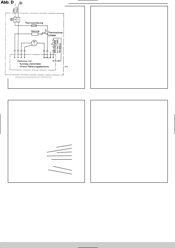
Schaltplan
T 500 E, TH 500,
TH 500 Z, TH 500 E mit im Gerät eingebauten Kurzwegzeitschaltern bzw. Infrarot-Näherungselectronic.
2

Schaltplan |
Schaltplan |
TH 500 mit externem Ein-/Ausschalter |
TH 500, TH 500 Z, TH 500 E mit Münzschalter |
|
|
DBeschreibung
|
1 |
Gehäusefläche/Diebstahlsicherung |
5 |
Anschlußleitung Gerät |
9 |
Leitungsdurchführung |
|
2 |
Montageplatte/Wandhalter |
6 |
Luft-Ansauggitter |
0 |
Anschlußleitung/Installation |
|
3 |
Unterputz-Steckdose |
7 |
Unterputzleitung |
q Netzklemme |
|
|
4 |
Sollbruchstelle |
8 |
Zugentlastungsschelle |
w Befestigungsbohrungen |
|
|
|
|
|
|
|
|
GB |
Description |
|
|
|
|
|
|
1 |
Housing surface/theft protection |
5 |
Power supply cable |
9 |
Lead-through |
|
2 |
Mounting plate/wall bracket |
6 |
Air intake grille |
0 |
Connecting cable/installation |
|
3 |
Flush socket |
7 |
Concealed wire |
q Mains terminal |
|
|
4 |
Predetermined breaking point |
8 |
Strain relief clamp |
w Mounting holes |
|
FDescription
1 |
Surface inférieur du boitier/Antivol |
5 |
Conducteur de raccordement de l’appareil |
9 |
Passage de la ligne |
2 |
Plaque de montage/Fixation au mur |
6 |
Grille d’aspiration d’air |
0 |
Ligne de raccordement/Installation |
3 |
Prise encastrée |
7 |
Conduite encastrée |
q Borne de réseau |
|
4 |
Point prédécoupé |
8 |
Bride de serrage |
w Trous de fixation |
|
IDescrizione
1 |
Piastra di copertura/sicurezza antifurto |
5 |
Cavo dell’apparecchio |
9 |
Apertura di passaggio per il cavo |
2 |
Supporto d montaggio/supporto da parete |
6 |
Griglia di aspirazione dell’aria |
0 |
Cavo di collegamento/installazione |
3 |
Presa sotto-intonaco |
7 |
Linea sotto-intonaco |
q Morsetto per l’allacciamento alla rete |
|
4 |
Punto di frattura |
8 |
Fascette di scarico della tensione |
w Fori di fissaggio |
|
3

EDescripción
1 |
Placa de cubierta/Aseguramiento anti-hurto |
5 |
Línea de connexión del aparato |
9 |
Boquilla de paso |
2 |
Placa de montaje/Dispositivo fijador mural |
6 |
Rejilla de aspiración de aire |
0 |
Línea de connexión/Instalación |
3 |
Caja de enchufe empotrada |
7 |
Línea eléctrica empotrada |
q Borne de red |
|
4 |
Punto teórico de rotura |
8 |
Brida presora de cables |
w Águjeros de fijación |
|
PDescrição
|
1 |
Face da caixa/Protecção contra furto |
5 |
Cabo de ligação do equipamento |
9 |
Passagem do condutor |
|
2 |
Placa de montagem/Suporte de parede |
6 |
Grade de aspiração de ar |
0 |
Cabo de ligação/Instalação |
|
3 |
Tomada embutida |
7 |
Condutor embutido |
q Terminal de rede |
|
|
4 |
Ponto de ruptura controlada |
8 |
Braçadeira de alívio de tracção |
w Furos de fixação |
|
|
|
|
|
|
|
|
DK |
Beskrivelse |
|
|
|
|
|
|
1 |
Tyversikring |
5 |
Apparat tilslutning |
9 |
Ledningsgennemføring |
|
2 |
Monteringsplade |
6 |
Luftindsugningsfilter |
0 |
Nettilslutning |
|
3 |
Forsænket stikdåse |
7 |
Skjult ledning |
q Netklemme |
|
|
4 |
Brudlinie |
8 |
Aflastning |
w Monteringspunkter |
|
NBeskrivelse
1 |
Kapsling/Tyverisikring |
5 |
Ledning app. |
9 |
Ledningsgjennomføring |
2 |
Montasjeplate/Veggholder |
6 |
Luftinntaksgitter |
0 |
Tilførselsledning |
3 |
Innfelt stikkontakt |
7 |
Skjult ledningsinst. |
q Nettklemme |
|
4 |
Svekking |
8 |
Strekkavlaster |
w Festehull |
|
SBeskrivning
|
1 Kåpans yta |
5 |
Anslutningsledning apparat |
9 |
Ledningsgenomföring |
|
|
2 |
Monteringsplatta/vägghållare |
6 |
Luftinsugningsgaller |
0 |
Anslutningsledning/installation |
|
3 |
Infällt uttag |
7 |
Infälld ledning |
q Nätklämma |
|
|
4 |
Avsett brottställe |
8 |
Dragavlastningsklämma |
w Fastsättningshål |
|
|
|
|
|
|
|
|
NL |
Beschrijving |
|
|
|
|
|
|
1 |
Huisoppervlakte/Diefstalveiligh |
5 |
Kabel |
9 |
Doorvoerleiding |
|
2 |
Montageplaat/Wandhouder |
6 |
Luchtaanzuigstuk |
0 |
Aansluiting/installatie |
|
3 |
Ingebouwd stopcontact |
7 |
Ingebouwde leiding |
q Kroonsteen |
|
|
4 |
Opangbeugel |
8 |
Trekontlaster |
w Bevestigingsgaatje |
|
|
|
|
|
|
|
|
PL |
Opis |
|
|
|
|
|
|
1 |
Powierzchnia obudowy/zabezpieczenie |
5 |
Przewód przy∏àczowy do urzàdzenia |
9 |
Przepust przewodowy |
|
|
przeciwkradzie˝owe |
6 |
Siatka zasysajàca powietrze |
0 Przewód przy∏àczowy/instalacja |
|
|
2 |
P∏ytka monta˝owa/podpora Êcienna |
7 |
Przewód podtynkowy |
q Zacisk sieciowy |
|
|
3 |
Podtynkowe gniazdko sieciowe |
8 |
Uchwyty odcià˝ajàce |
w Otwory do zamocowania |
|
|
4 |
Miejsce prze∏omu (p´kni´cia) |
|
|
|
|
HLeírás
1 |
FedŒlemez/lopás elleni biztosítás |
5 |
Csatlakozóvezeték |
9 |
Vezetékátvezetés |
2 |
SzerelŒlemez/falitartó |
6 |
LevegŒszívó-rács |
0 Hálózati csatlakozó kapocs |
|
3 |
Süllyesztett dugaszolósaljzat |
7 |
Süllyesztett vezeték |
q RögzítŒ furatok |
|
4 |
Kijelölt töréshely |
8 |
HúzásmegszüntetŒ bilincs |
w RögzítŒ furatok |
|
|
|
|
|
|
|
4

DHändetrockner T 500, T 500 E Haartrockner TH 500, TH 500 Z, TH 500 E
Wir haben diese Gebrauchsanleitung erstellt, damit Sie Ihr neues Gerät schnell und umfassend kennenlernen.
●Bitte lesen Sie vor Inbetriebnahme des Gerätes diese Anleitung aufmerksam durch. Sie gibt wichtige Hinweise für die Sicherheit, den Gebrauch, die Wartung und Entsorgung.
●Machen Sie sich in der Reihenfolge dieser Gebrauchsanleitung mit Ihrem neuen Gerät und seinen verschiedenen Funktionen vertraut.
●Beachten Sie alle Hinweise und Erklärungen, die sich auf die richtige Bedienung und Behandlung beziehen. Damit erreichen Sie ständige Einsatzbereitschaft und eine lange Lebensdauer Ihres Gerätes.
●Besonders sind die Hinweise zu berücksichtigen, die die Sicherheit betreffen. Sie helfen, Unfälle zu verhüten und Ihr Gerät vor Schaden zu schützen.
●Bewahren Sie die Gebrauchsanleitung auf, sie kann Ihnen auch später noch in manchen Fällen ein nützlicher Helfer sein.
Dieses Gerät entspricht den anerkannten Regeln der Technik und den einschlägigen Sicherheitsbestimmungen für Elektrogeräte Der Hersteller haftet nicht für evtl. Schäden, die durch nicht bestimmungsgemäßen Gebrauch oder falsche Bedienung verursacht werden.
2. Lieferumfang.
Haarbzw. Händetrockner
4Dübel
4Halbrundholzschrauben 1 Netzklemme q
2 Senkblechschrauben für Abdeckplatte 1
2 Zugentlastungsschellen 8
4Linsenblechschrauben für Zugentlastungsschellen
1 Schraubendreher (bei TH 500 Z und allen E-Typen)
3. Technische Daten
|
|
|
Warmluft- |
|
Warmluft- |
|
|
|
|
|
Händetrockner |
|
Haartrockner |
|
|
|
|
|
T 500 |
T 500 E |
TH 500 |
TH 500 Z |
TH 500 E |
Nennleistung |
1800 |
Watt |
X |
X |
X |
X |
X |
Heizleistung |
1700 |
Watt |
X |
X |
X |
X |
X |
Motorleistung |
100 |
Watt |
X |
X |
X |
X |
X |
Luftstrom |
38 I/s |
X |
X |
X |
X |
X |
|
Abmessungen: |
|
|
|
|
|
|
|
B 258, T 152, H 315 mm |
|
|
X |
X |
X |
X |
X |
B 261, T 155, H 345 mm |
|
|
|
|
|
|
|
Gewicht mit Wandhalter: |
3,2 kg |
X |
X |
X |
X |
X |
|
Prüfzeichen: |
|
|
|
|
|
|
|
v g c e q IP 23 |
|
|
|
|
|
|
|
5

Ausstattung: |
T 500 |
T 500 E |
TH 500 |
TH 500 Z |
TH 500 E |
electronischer Kurzweg-Zeitschalter |
X |
|
|
|
|
Schalterlaufzeit 32 sec. |
|
|
|
|
|
electronischer Kurzweg-Zeitschalter |
|
|
|
X |
|
Schalterlaufzeit ca. 4 min. |
|
|
|
|
|
electronischer Infrarot-Näherungsschalter |
|
X |
|
|
X |
ohne Schalteinrichtung (zu betreiben z. B. mit |
|
|
X |
|
|
Münzzeitschalter MZS 4) |
|
|
|
|
|
Sicherheits-Netzstecker-Anschluß |
X |
X |
X |
X |
X |
Sicherheits-Temperaturbegrenzer |
X |
X |
X |
X |
X |
Sensor-Sicherheitsabschaltung |
|
X |
|
|
X |
Thermo-Schmelzsicherung |
X |
X |
X |
X |
X |
integrierte Montageplatte |
X |
X |
X |
X |
X |
Diebstahlsicherung durch Abdeckplatte |
X |
X |
X |
X |
X |
absaugbares Lufteintrittsgitter |
X |
X |
X |
X |
X |
|
|
|
|
|
|
4. Montageanleitung.
Mit der Montage ist ein Fachmann zu beauftragen, damit gewährleistet ist, daß das Gerät unter Beachtung der Sicherheitsvorschriften angeschlossen wird. In Räumen mit Duschen und Badewannen darf das Gerät nicht innerhalb der in den VDE-Vorschriften festgelegten Sicherheitsbereiche (0,6 m zum Duschbzw. Badewannenrand und 1,2 m zu Brauseköpfen) angebracht werden. In der elektrischen Installation muß ein Schalter mit einer Kontaktöffnung >= 3 mm vorhanden sein, der das Gerät allpolig abschaltet.
5. Montagereihenfolge.
Das servicefreundliche Montagekonzept
Das T 500-Montage-System ermöglicht eine einfache, servicefreundliche Wandanbringung, ohne das Gerät zu öffnen. Praktisch haben wir das Gerät in zwei Komponenten aufgeteilt: Der Installateur setzt eine Steckdose (oder einen Festanschluß), schraubt die Montageplatte an, schiebt das betriebsfertige Gerät auf, steckt den Netzstecker ein (oder schließt an), schraubt die Diebstahlsicherung auf – fertig. Einfacher geht’s nicht!
1.Die (nicht festgeschraubte) Abdeckplatte 1 nach unten aus dem Gerät ziehen. Die auf der Geräterückseite einge-
schobene Montageplatte 2 ebenfalls nach unten herausziehen.
2.Nach Festlegung des Anbringungsortes die 4 Befestigungsbohrungen w mit der Montageplatte 2 als Schablone anzeichnen, bohren (8 mm Ø), Dübel einsetzen und die Montageplatte mit den A beiliegenden Halbrundholzschrauben befestigen. Wir empfehlen die Anbringung in einer Höhe entsprechend Abb. A, B oder C. Eine solide Befestigung an einer massiven Wand muß gewährleistet sein.
3.Die 5 nachstehend beschriebenen Anschlußarten sind möglich.
3.1Anbringung über installierte Unterputz-Steckdose.
Der obere Teil der Abdeckplatte 1 wird nicht benötigt. Brechen Sie ihn an der Sollbruchstelle 4 ab. Nach Befestigung der Montageplatte 2 entspr. Abb. B das Gerät von oben auf die Montageplatte schieben, den Stecker in die Steckdose 3 stecken und das Gerät ganz nach unten schieben. Abdeckplatte mit den 2 beiliegenden Senkblechschrauben befestigen.
3.2Unterputzleitung.
Anschluß über eine (anstatt der Steckdose) aus der Wand kommende Unterputzleitung 7. Montageplatte 2 entspr. Abb. C an der Wand befestigen. Die Abdeckplatte von unten in die Montageplatte schieben und dabei die aus der Wand kommende Leitung durch die Öffnung in
6

der Abdeckplatte führen. Beiliegende Netzklemme q einsetzen. An der Anschlußleitung 5 des Gerätes den Stecker abschneiden, die Leitung abmanteln, abisolieren und Aderendhülsen anquetschen. Beide Leitungen entsprechend Abb. C anschließen. Auf richtigen Anschluß von L (braun) und N (blau) achten. Die Anschlußleitung des Gerätes mit beiliegender Zugentlastungsschelle 8 sichern.
Gerät ganz nach unten auf die Abdeckplatte schieben und die 2 beiliegenden Senkblechschrauben eindrehen.
3.3Aufputzleitung von oben.
Hierzu die auf der Geräterückseite, oben Mitte, vorgesehene Leitungsdurchführung ausbrechen. Nach Befestigung der Montageplatte 2 entspr. Abb. C die Aufputzleitung auf der Montageplatte nach unten unter die Abdeckplatte 1 und durch die Öffnung führen. Der weitere Anschluß erfolgt wie unter 3.2, 2. Absatz beschrieben.
3.4Aufputzleitung von unten.
Hierzu die in der Abdeckplatte 1 unten Mitte, vorgesehene Leitungsdurchführung 9 ausbrechen. Nach Befestigung der Montageplatte 2 entspr. Abb. C die Aufputzleitung durch die Öffnung in der Abdeckplatte führen. Der weitere Anschluß erfolgt wie unter 3.2, 2. Absatz beschrieben.
3.5Anschlußleitung mit Stecker.
Anschluß an eine in der Nähe vorhandenen Steckdose mit einer flexiblen Anschlußleitung mit Stecker. Hierzu die in der Abdeckplatte 1, unten Mitte, vorhandene Leitungsdurchführung 9 ausbrechen. Die Abdeckplatte von unten in die Montageplatte schieben. Beiliegende Netzklemme q einsetzen. An der Anschlußleitung 5 des Gerätes den Stecker abschneiden, die Leitung abmanteln, abisolieren und Aderendhülsen anquetschen. Anschlußleitung mit Stecker in gleicher Weise konfektionieren, und durch die Offnung in der Abdeckplatte führen. Beide Leitungen entspr. Abb. C anschließen und mit beiliegenden Zugentlastungsschellen 8 sichern.
Gerät ganz nach unten auf die Abdeckplatte schieben und die 2 beiliegenden Senkblechschrauben eindrehen.
Die Geräte sind jetzt betriebsbereit.
6. Schaltmöglichkeiten.
T 500, TH 500 Z
Bei T 500 und TH 500 Z electronischen Kurzweg-Zeit- schalter betätigen. Schalterlaufzeit bei T 500 32 sec. bei TH 500 Z 4 min.
Die Geräte schalten automatisch ab.
Die Schalterlaufzeit bei TH 500 Z kann vom Fachmann verändert werden. Sie ist in 9 Stufen einstellbar auf 1–9 min.
Hierzu den beiliegenden Schraubendreherstift in die Bohrung links im Ansauggitter 6 stecken und den eingebauten Schalter nach links auf 3–2–1 min. oder rechts auf 5–6–7–8–9 min. verstellen.
Beachten Sie, daß die Schalterstellung O eine Blindstellung ist, bei der das Gerät nicht funktioniert.
T 500 E, TH 500 E
Die Geräte werden durch eine Infrarot-Näherungselectronic berührungslos einund ausgeschaltet.
Der Schaltabstand (Abstand zwischen Geräteunterkante und Händen bzw. Kopf) beträgt bei T 500 ca. 15 cm und bei TH 500 ca. 40 cm. Die Schaltempfindlichkeit kann vom Fachmann verändert werden. Hierzu den beiliegenden Schraubendreherstift in die Öffnung links im Ansauggitter 6 stecken und das eingebaute Potentiometer nach links (unempfindlicher) oder nach rechts (empfindlicher) verstellen. In sehr hellen Räumen ist eine unempfindlichere Einstellung notwendig.
TH 500
Dieses Gerät wird ohne Schalter geliefert. Es wird durch einen Münzzeitschalter MZS 4 einen handelsüblichen Ein/Ausschalter oder einen Wandzeitschalter betätigt, der in üblicher Höhe neben dem Gerät an der Wand befestigt und nach Schaltplan s. Abb. E bzw. F angeschlossen wird.
Sensor-Sicherheitsabschaltung T 500 E, TH 500 E,
Die eingebaute Electronic verhindert Dauerlauf bei abgedecktem Infrarot-Näherungsschalter z. B. KaugummiVandalismus.
T 500-Modelle schalten dann nach 2 min. und TH 500Modelle nach 10 min. ab. Nach Beseitigung der Störquelle sind die Trockner wieder betriebsbereit.
7

Münzzeitschalter MZS 4
Beim Betreiben der Haartrockner TH 500 Z/E mit einem Münzzeitschalter bleibt die Funktion der Schalterbzw. die Funktion der Näherungselectronic erhalten. Der MZS 4 wird zur schnellen Amortisation und zum Schutz vor mißbräuchlicher Benutzung eingesetzt.
7. Höheneinstellung für Starmix Haartrockner.
Die formschöne robuste Starmix Höheneinstellung THH 500 ermöglicht es, den Haartrockner stufenlos und individuell der Körpergröße anzupassen. Dadurch wird besonders Kindern und Rollstuhlfahrern das Haaretrocknen wesentlich erleichtert. Alternativ zur Höheneinstellung können Sie auch zwei Haartrockner in einem Höhenunterschied von 40 cm montieren (Reichweite des electronischen Infrarot-Nähe- rungsschalters max. 40 cm).
8. Reinigung und Pflege.
Das Luft-Ansauggitter 6 an der Geräteunterseite zur Reinigung von anhaftenden Flusen und Staub bei Bedarf mit Staubsauger-Fugendüse absaugen. Festhaftende Verschmutzung im Gitter mit Bürste entfernen.
9.Sicherheitshinweise.
–Prüfen Sie vor Anschluß des Gerätes, ob die auf dem Typenschild angegebene Spannung mit derjenigen Ihres Hausanschlusses übereinstimmt. Das Typenschild finden Sie auf der unteren, schrägen Gehäusefläche 1.
–Bitte beachten Sie, daß beim unsachgemäßen Umgang mit Elektrogeräten Gefahren entstehen können, die möglicherweise von Kindern nicht erkannt werden.
–Übergeben Sie diese Gebrauchsanweisung auch anderen Benutzern des Gerätes, damit auch diese sich über alle Funktionen und Hinweise informieren können.
–Schalten Sie grundsätzlich vor allen Eingriffen und Reinigung die Netzzuleitung allpolig ab.
8

GB |
Hand dryers T 500, T 500 E |
Hair dryers TH 500, TH 500 Z, TH 500 E |
|
|
|
These Operating Instructions will ensure that you can quickly and comprehensively familiarize yourself with the new appliance.
●Please, read the following carefully before using the appliance for the first time. These instruction give important information concerning use, safety, care and maintenance, and waste disposal.
●Familiarize yourself in the same sequence as these Operating Instructions with the new appliance and its different functions.
●Observe all instructions for the correct operation and care of the appliance to maintain its operating readiness at all times and to ensure a long and dependable service life.
●Ensure that all instructions concerning safety are carefully observed to prevent accidents and to protect the appliance against damage.
●Keep these Operating Instructions in a safe place as they could prove to be a useful source of reference on a future occasion.
The appliance complies with the accepted rules of technology and the requisite laws on the safety of electrical appliances. The manufacturer cannot be held liable for possible damage resulting from incorrect appliance use or operation.
2. Items supplied.
Hair or hand dryer
4dowels
4round-head wood screws 1 mains terminal q
2 countersunk sheet metal screws for the cover plate 1 2 strain relief clamps 8
4pan-head tapping screws for the strain relief clamps 1 screwdriver (with TH 500 Z and all E models)
3. Technical Data.
|
|
|
Hot air |
|
Hot air |
|
|
|
|
hand dryer |
|
hair dryer |
|
||
|
|
T 500 |
|
T 500 E |
TH 500 |
TH 500 Z |
TH 500 E |
Rated capacity |
1800 watt |
X |
|
X |
X |
X |
X |
Heating capacity |
1700 watt |
X |
|
X |
X |
X |
X |
Motor output |
100 watt |
X |
|
X |
X |
X |
X |
Air flow rate |
38 I/s |
X |
|
X |
X |
X |
X |
Dimensions: |
|
|
|
|
|
|
|
W 258, D 152, H 315 mm |
|
X |
|
X |
X |
X |
X |
W 261, D 155, H 345 mm |
|
|
|
|
|
|
|
Weight with wall bracket: |
3,2 kg |
X |
|
X |
X |
X |
X |
Test symbols: |
|
|
|
|
|
|
|
v g c e q IP 23 |
|
|
|
|
|
|
|
9

Features: |
T 500 |
T 500 E |
TH 500 |
TH 500 Z |
TH 500 E |
Electronic short-duration timer |
X |
|
|
|
|
Timer running time 32 sec. |
|
|
|
|
|
Electronic short-duration timer |
|
|
|
X |
|
Timer running time approx. 4 min. |
|
|
|
|
|
Electronic infared proximity switch |
|
X |
|
|
X |
Without switching facility (for coin-operated |
|
|
X |
|
|
timer MZS 4) |
|
|
|
|
|
Safety mains connection |
X |
X |
X |
X |
X |
Safety temperature limiter |
X |
X |
X |
X |
X |
Safety sensor switch-off |
|
X |
|
|
X |
Thermal safety fuse |
X |
X |
X |
X |
X |
Integrated mounting plate |
X |
X |
X |
X |
X |
Theft-proofing cover plate |
X |
X |
X |
X |
X |
Air-inlet grille, cleanable by suction |
X |
X |
X |
X |
X |
|
|
|
|
|
|
4. Mounting instructions.
The appliance must be installed by a specialist to ensure that the requisite safety rules for the connection of electrical appliances are observed. In rooms with showers and baths the appliance must not be installed within the safety areas set forth in the VDE German standard (0.6 m from the edge of showers or baths, and 1.2 m from shower heads). The electrical wiring must incorporate a switch with a contact opening of >= 3 mm for all-pole disconnection of the appliance.
5. Mounting sequence.
The service friendly mounting concept
The T 500 mounting system ensures simple wall installation without having to open the appliance. For reasons of practicality the appliance is subdivided into 2 sections. The electrician must first install a socket outlet (or a permanent connection), then screw the mounting plate to the wall, slide the ready-to-operate appliance onto the plate, plug the power supply cable into the socket (or connect the permanent wiring), screw the anti-theft plate onto the appliance – and that’s it. It just couldn’t be easier!
1.Pull the cover plate 1 (which is not screwed tight) down out of the appliance.
The mounting plate 2 inserted in the back of the appliance is likewise pulled down.
2.After having determined the point of installation, mark out the 4 mounting holes w using the mounting plate 2 as a template for this purpose, and then drill 8 mm diameter holes. Insert the dowels and fasten the mounting plate with the 4 supplied wood screws. The appliance should be mounted at a level indicated in figs. A, B or C. The appliance must be firmly mounted on a solid wall.
3.The 5 subsequently described methods of connection are possible.
3.1Connection by way of flush-mounted socket:
The top part of the cover plate 1 is not required. Break it off at the predetermined breaking point 4. Fasten the mounting plate 2 as indicated in fig. B, push the appliance from above onto the mounting plate, plug the power supply cable into the socket outlet 3, and push the appliance all the way down. Fasten the cover plate with the 2 supplied countersunk sheet metal screws.
3.2Connection by way of concealed wiring:
Connect with the concealed wire 7 coming out of the wall (in place of the socket). Fasten the mounting plate 2 to the wall as indicated in fig. C. Push the mount plate from underneath into the mounting plate. Conduct the wire coming out of the wall through the hole in the
10
cover plate. Insert the supplied mains terminal q. Cut the plug off the power supply cable 5.
Remove the cable sheath and conductor insulation, and crimp on the wire end sleeves. Connect the two conductors as shown in fig. C. Ensure that L (brown) and N (blue) are correctly connected. Secure the connecting cable of the appliance-with the supplied strain relief clamp 8.
Push the appliance right down onto the cover plate and secure with the 2 supplied countersunk sheet metal screws.
3.3Connection from above by way of surface-mounted wiring:
Break out the lead-through 9 at the top in the middle of the back of the appliance. Fasten the mounting plate 2 as indicated in fig. C. Conduct the surfacemounted cable on the mounting plate down to the cover plate 1 and pass it through the hole.
Connect as described in section 3.2.2.
3.4Connection from below by way of surface-mounted wiring:
Break out the predetermined lead-through 9 at the bottom in the middle of the cover plate 1. Fasten the mounting plate 2 as indicated in fig. C. Conduct the surface-mounted cable through the opening in the cover plate. Connect as described in section 3.2.2.
3.5Connection by way of power supply cable with plug: Connection to an adjacent mains socket by way of a flexible power supply cable with plug. For this purpose break out the predetermined lead-through 9 at the bottom in the middle of the cover plate 9. Push the cover plate from underneath into the mounting plate. Insert the supplied mains terminal q.
Cut the plug off the power supply cable 5 of the appliance. Remove the cable sheath and conductor insulation and crimp on the wire end sleeves. Prepare the free end of the power supply cable with plug in the
same manner, and conduct it through the opening in the cover plate. Connect the two cables as indicated in fig. C., and secure with the 2 supplied strain relief clamps 8.
Push the appliance right down onto the cover plate and secure with the 2 supplied countersunk sheet metal screws.
The appliance is now ready for operation.
6. Switching functions.
T 500, TH 500 Z
Actuate the electronic short-duration timer on the T 500 and TH 500 Z. Timer running time on the T 500 32 sec. on the TH 500 Z 4 min.
The appliances are automatically switched off.
The timer running time on the TH 500Z can be changed by a specialist. It is adjustable in 9 settings from 1–9 min. For this purpose insert the screwdriver pin in the hole on the left-hand side of the air intake grille 8 and turn the built-in switch anti-clockwise to 3–2–1 min., or clock wise to 5–6–7–8–9 min.
The O-position of the switch is a blind setting in which the appliance will not operate.
T 500 E, TH 500 E
The appliances are switched ON/OFF by an electronic infrared proximity switch.
The switch spacing between the bottom edge of the appliance and the hands or head for the T 500 is approx. 15 cm, and for the TH 500 approx. 40 cm. The switching sensitivity can be changed by a specialist. For this purpose insert the screwdriver pin in the opening on the left-hand side of the air intake grille 8 and turn the built-in potentiometer anti-clockwise to reduce the sensitivity, or clockwise to increase the sensitivity. Bright rooms require a lower sensitivity setting.
TH 500
This appliance is supplied without switch. It can be operated by the MZS 4 coinoperated timer, a normal ON/OFF switch or a wall-mounted timer. It is mounted on the wall at the same level as the appliance and connected according to the circuit diagram, see fig. E or F.
T 500 E, TH 500 E sensor safety switch off
The built-in electronic safety circuit prevents continuous operation in the event that the infrared proximity switch is covered, e.g. chewing-gum, vandalism.
T 500 models switch off after 2 minutes, and TH 500 models after 10. The dryers are once again operable as soon as the fault has been remedied.
MZS 4 coin-operated timer
The function of the power-saving electronic switch and the proximity switch are retained when the TH 500 Z/E hair dryers are operated with a coin-operated timer. Installation of the MZS 4 will ensure that the cost of the hair dryers will be quickly refunded and protect the appliance against improper use.
11

7. Height adjustment for Starmix hair dryer.
Height adjustment of the strong attractively designed Starmix THH 500 is continuously variable so that the hair dryer can be easily adapted to the individual’s height. This makes it substantially easier for children and people in wheelchairs to dry their hair.
As an alternative to height adjustment it is also possible to mount two separate hair dryers at a height difference of 40 cm (the maximum range of the electronic infrared proximity switch is 40 cm).
8. Cleaning and care.
Use a vacuum cleaner with crevice nozzle to remove fluff and dust adhering to the air intake grille 6 at the bottom of the appliance. Stubborn grime in the grille must be removed with a brush.
9.Safety instructions.
–Before connecting the appliance check that the voltage specified on the rating plate matches the mains voltage. The rating plate is located on the lower sloping housing surface 1.
–Improper use of electrical appliances can result in hazards that may not be recognized by children.
–Make these Operating Instructions available to other users so that they can inform themselves of all the functions of the appliance.
–All-pole disconnection from the power supply is imperative before cleaning or repairing the appliance.
12

FSèche-mains: T 500, T 500 E Sèche-cheveux: TH 500, TH 500 Z, TH 500 E
Nous avons établi ce mode d’emploi, pour que vous appreniez rapidement à connaître votre nouvel appareil.
●Veuillez lire entièrement et attentivement ces instructions avant la mise en service de l’appareil. Elles donnent des indications importantes en ce qui concerne la sécurité, I’utilisation, I’entretien et les précautions pour l’environnement.
●Apprenez à connaître votre nouvel appareil et ses différentes fonctions en suivant l’ordre de ce mode d’emploi.
●Respectez les indications et les explications pour obtenir un maniement et un entretien corrects. Ainsi, vous serez sûrs que votre appareil restera en ordre de marche et aura une longévité exceptionnelle.
●Vous devez surtout tenir compte des instructions qui
concernent la sécurité. Elles vous aideront à éviter des accidents et à protéger votre appareil d’éventuels dommages.
●Conservez ce mode d’emploi: il pourra plus tard dans bien des cas vous être une aide précieuse.
Cet appareil est conforme aux normes techniques et aux prescriptions de sécurité en vigueur relatives aux appareils électriques. Le constructeur n’est pas responsable de dommages éventuels, qui auraient été causés par une utilisation non appropriée ou une erreur de maniement.
2. Livraison.
Sèche-cheveux ou sèche-mains
4chevilles
4vis à bois à tête demi-ronde 1 borne de réseau q
2 vis à tôle à tête conique pour plaque de recouvrement 1 2 brides de serrage 8
4vis à tôle à tête conique-bombée pour brides de serrage 1 tournevis en plastique (pour le TH 500 Z et tous les
types E)
3. Données techniques.
|
|
|
Sèche-mains |
|
Sèche-chevaux |
|
|||
|
|
|
à air chaud |
|
|
à air chaud |
|
||
|
|
|
T 500 |
T 500 E |
TH 500 |
|
TH 500 Z |
|
TH 500 E |
Puissance nominale |
1800 |
W |
X |
X |
X |
|
X |
|
X |
Puissance de chauffage |
1700 |
W |
X |
X |
X |
|
X |
|
X |
Rendement du moteur |
100 |
W |
X |
X |
X |
|
X |
|
X |
Débit à l’air |
38 I/s |
X |
X |
X |
|
X |
|
X |
|
Poids des appareils: |
|
|
|
|
|
|
|
|
|
B 258, T 152, H 315 mm |
|
|
X |
X |
X |
|
X |
|
X |
B 261, T 155, H 345 mm |
|
|
|
|
|
|
|
|
|
Poids avec fixation: |
3,2 Kg |
X |
X |
X |
|
X |
|
X |
|
Signes d’homologations: |
|
|
|
|
|
|
|
|
|
v g c e q IP 23 |
|
|
|
|
|
|
|
|
|
13

Equipment: |
T 500 |
T 500 E |
TH 500 |
TH 500 Z |
TH 500 E |
Interrupteur électronique avec minuterie extra courte; |
X |
|
|
|
|
Durée de fonctionnement 32 secondes. |
|
|
|
|
|
Interrupteur électronique avec minuterie extra courte; |
|
|
|
X |
|
Durée de fonctionnement environ 4 minutes. |
|
|
|
|
|
Interrupteur électronique de proximité à infrarouges |
|
X |
|
|
X |
Sans mécanisme de couplage (à utiliser par exemple |
|
|
X |
|
|
avec la minuterie de monnayeur MZS 4) |
|
|
|
|
|
Raccort de sécurité à la prise de secteur |
X |
X |
X |
X |
X |
Régulateur de température de sécurité |
X |
X |
X |
X |
X |
Plaque de montage intégrée |
|
X |
|
|
X |
Antivol par plaque de recouvrement |
X |
X |
X |
X |
X |
Grille d’entrée d’air nettoyable à l’aspirateur |
X |
X |
X |
X |
X |
|
|
|
|
|
|
4. Instructions de montage.
Faire effectuer le montage par un spécialiste afin d’être certain que l’appareil est connecté en conformité avec les prescriptions de sécurité. Dans les pièces équipées de douches ou de baignoires, on ne doit pas installer l’appareil dans les secteurs spécifiés par les prescriptions de sécurité VDE (à 0,6 m du bord de la douche ou de la baignoire et à 1,2 m de la pomme de la douche). L’installation électrique doit comporter un interrupteur ayant une ouverture de contact à 3 mm qui mette l’appareil hors circuit sur tous les pôles.
5. Marche à suivre pour le montage.
Un concept de montage facile à réaliser.
Le système de montage T 500 permet de procéder de manière simple et facile à la pose de l’appareil contre le mur sans l’ouvrir. Pour une pose pratique, nous avons divisé l’appareil en deux éléments: I’installateur pose une prise (ou un raccordement fixe), visse la plaque de montage, glisse dessus l’appareil prêt à fonctionner, enfonce la prise (ou fait le branchement) et termine en vissant l’antivol. On ne peut pas faire plus simple!
1.Retirer de l’appareil en la tirant vers le bas la plaque de recouvrement (non vissée). Retirer de la même façon la plaque de montage glissée à l’arrière de l’appareil.
2.Après avoir déterminé l’endroit où sera fixé l’appareil,
marquer les 4 trous de fixation w en se servant de la plaque de montage 2 comme gabarit, percer les trous (8 mm de diamètre), introduire les chevilles et fixer la plaque de montage avec les 4 vis à bois à tête demi-ronde qui y sont jointes. Nous conseillons de fixer l’appareil à une hauteur correspondant aux figures A, B, ou C. Il faut être absolument certain que le dispositif est fixé solidement dans un mur plein.
3.Les 5 méthodes de branchement décrites ci-dessous sont possibles:
3.1Branchement par une prise encastrée.
On n’a pas besoin de la partie supérieure de la plaque de recouvrement. La casser à l’endroit prévue à cet effet. Après fixation de la plaque de montage 2 suivant la figure B, pousser par en haut l’appareil sur la plaque de montage, enfoncer la fiche dans la prise 3 et pousser l’appareil tout en bas. Fixer la plaque de recouvrement avec les deux vis à tôle à tête coniques jointes.
3.2Fil encastré
Branchement à un conducteur électrique encastré 7 sortant du mur (à la place de la prise). Fixer au mur la plaque de montage 2 suivant la figure C. Faire glisser la plaque de recouvrement par le bas dans la plaque de
montage et en même temps faire passer le conducteur électrique au mur par l’orifice de la plaque de recouvrement. Mettre en place la borne de réseau q. Sectonner la fiche du cordon de branchement 7 de l’appareil, dénuder les brins et raccorder. Brancher les deux fils suivant la figure C. Veiller à brancher correctement les fils L (marron) et N (bleu). Bloquer le cordon de
14

branchement de l’appareil avec les brides de serrage jointes. Enfoncer l’appareil en le faisant glisser sur la plaque de haut en bas et verrouiller l’appareil avec les 2 vis jointes.
3.3Branchement en saillie par le haut
Pour ce faire libérer le passage prévu pour faire traverser le conducteur se trouvant en haut et au milieu du panneau arrière de l’appareil. Après fixation de la plaque de montage 2 suivant la fiugre C, faire passer le cordon apparent sur la plaque de montage en bas, en passant par dessous la plaque de recouvrement 1 et à travers l’orifice. Le reste du branchement s’effectue comme décrit au paragraphe 3.2.
3.4Branchement en saillie par le bas
Pour ce faire, libérer le passage 9 prévu pour faire
traverser le cordon en bas et au milieu de la plaque de recouvrement 1. Après fixation de la plaque de montage 2 suivant la figure C, faire le branchement en saillie en passant par l’orifice de la plaque de recouvrement. Le reste du branchement s’effectue comme décrit au paragraphe 3.2.
3.5Cordon de branchement avec fiche
On effectue ce branchement avec un cordon flexible avec fiche sur une prise se trouvant à proximité. Pour ce faire, libérer le passage 9 en bas et au milieu de la plaque de recouvrement 1. Faire glisser la plaque de recouvrement par en-dessous dans la plaque de montage. Utiliser la barre de réseau q jointe.
Sectionner la fiche du cordon de branchement 5 de l’appareil, dénuder le fil et attacher les cosses des fils. Préparer de la même manière le cordon avec fiche et le faire passer par l’orifice de la plaque de recouvrement. Brancher les deux fils suivant la figure C et les bloquer avec les brides 8 jointes. Repousser l’appareil vers le bas et visser les deux vis à tôle à tête conique jointes.
Les appareils sont maintenant prêts à fonctionner!
6. Possibilities de branchement.
T 500, TH 500 Z
Pour les T 500 et TH 500 Z actionner la minuterie électronique extra-courte. Durée de fonctionnement pour T 500: 32 secondes; pour TH 500 Z: 4 minutes.
Les appareils s’arrêtent automatiquement.
La durée de fonctionnement du TH 500 Z puet être modifiée par un spécialiste. Elle est réglable en 9 échelons de 1 à 9 minutes.
Pour ce faire, enfoncer le tournevis spécial en plastique dans le trou à gauche de la grille d’aspiration 6 et régler le commutateur intègre sur 3–2–1 minutes en tournant vers la gauche et sur 5–6–7–8–9 minutes en tournant vers la droite. Veuillez noter que le réglage O est une position déwattée et que l’appareil ne fonctionne pas sur cette position.
T 500 E, TH 500 E
Les appareils sont mis en route et arrêtés sans contact à l’aide d’un système électronique de détection de proximité à infra-rouge. La distance de déclenchement (distance entre l’extrémité inférieure de l’appareil et les mains ou la tête) est d’environ 15 cm pour le T 500 et 40 cm pour le TH 500. La sensibilité de déclenchement peut être modifiée par un spécialiste. Pour ce faire, enfoncer la goupille du tournevis dans le trou à gauche de la grille d’aspiration 6 et régler le potentiomètre intégré vers la gauche (moins sensible) ou vers la droite (plus sensible). Dans les locaux très clairs, il faut procéder à un réglage sur une position moins sensible.
TH 500
Cet appareil est livré sans commutateur. ll est actionné par une minuterie à pièces de monnaie MZS 4 un interrupteur de marche/arrêt courant dans le commerce et une minuterie murale fixée au mur à la hauteur habituelle à côté de l’appareil qu’on branche selon le plan électrique, figure E ou F.
Coupe-circuit de sécurité du détecteur T 500 E, TH 500 E
Le système électronique intégré évite que l’appareil marche sans arrêt lorsque le détecteur de proximité à infra-rouge est recouvert, par exemple lorsqu’un voyou colle un chewing-gum dessus. Dans ce cas, les modèles TH 500 au bout de 10 minutes. Lorsque l’origine de la panne est éliminée, les appareils sont à nouveau prêts à servir.
15

Minuterie à pièces de monnaie MZS 4
Lorsque les sèche-cheveux TH 500 Z/E fonctionnent avec une minuterie à pièas de monnaie, les commutateurs ou le système électronique de détection de proximité continuent à fonctionner. On utilise la MZS 4 pour obtenir un amortissement rapide et pour éviter une utilisation abusive.
7. Réglage en hauteur pour sèche-cheveux Starmix.
Ce réglage en hauteur pour sèche-cheveux STARMIX permet d’adopter à la hauteur désirea le séchoir à la taille des individus. Cela permet aux enfants et aux handicapés de se sécher les cheveux beaucoup plus facilement. Une autre possibilité consiste à monter deux sèche-cheveux à des hauteurs différentes distantes de 40 cm (portée maximale du détecteur de proximité à infra-rouge 40 cm).
8. Nettoyage et entretien.
Aspirer la grille d’aspiration d’air 6 sous l’appareil avec le suceur de l’aspirateur pour le débarasser des impuretés et de la poussière qui s’y accrochent. Brosser les saletés qui restent collées.
9.Conseils de sécurite.
–Avant de raccorder l’appareil, contrôler si le voltage indiqué sur la plaquette signalétique correspond à celui que vous utilisez. La plaquette signalétique se trouve sur la face inférieure du boitier.
–Veuillez tenir compte des dangers causés par une mauvaise utilisation des appareils électriques, ces dangers n’étant pas connus des enfants.
–Transmettez ces instructions aux autres personnels utilisant cet appareil, afin qu’elles puissent être informées de toutes les fonctions et instructions diverses.
–Avant toute intervention ou nettoyage, déconnecter l’appareil.
16
 Loading...