


HX-870
Page 1HX870
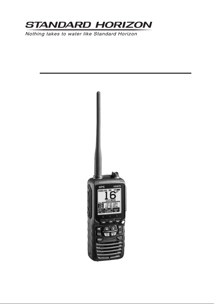
HX870
6 Watt VHF/FM
Floating Class D DSC Marine Transceiver with GPS
Owner’s Manual

Page 2
HX870
TABLE OF CONTENTS
Quick Reference Guide ............................................................................... 4
Introduction ..................................................................................................5
1 GENERAL INFORMATION ..................................................................... 6
2 PACKING LIST .......................................................................................6
3 OPTIONAL ACCESSORIES ................................................................... 7
4 ONLINE WARRANTY REGISTRATION (in USA or Canada only) .......8
5 ABOUT THIS RADIO .............................................................................. 9
5.1 PROHIBITED COMMUNICATIONS .............................................9
5.2 ABOUT VHF RADIO .................................................................... 9
5.3 DISTRESS AND HAILING (CHANNEL 16) ..................................9
5.4 CALLING ANOTHER VESSEL (CHANNEL 16 OR 9)................10
5.5 MAKING TELEPHONE CALLS .................................................. 11
5.6 BRIDGE CHANNELS 13 AND 67 .............................................. 11
5.7 AUTOMATED RADIO CHECK SERVICE ..................................12
6 GETTING STARTED.............................................................................13
6.1 BATTERIES AND CHARGERS..................................................13
6.1.1 Battery Safety ..................................................................13
6.1.2 Rechargable Battery Installation/Removal .......................15
6.1.3 Battery Life Information ....................................................15
6.1.4 Using the SBH-12 Charger Cradle ...................................16
6.1.5 Installation of the SBT-13 Battery Case ...........................17
6.2 BELT CLIP INSTALLATION / REMOVAL ...................................18
6.3 ATTACHING AN ANTENNA .......................................................18
6.4 CHECKING GPS SIGNAL (GPS STATUS DISPLAY) ................19
6.5 CHANGING THE GPS TIME .....................................................20
6.6 CHANGING THE TIME LOCATION ...........................................21
6.7 CHANGING THE TIME FORMAT ..............................................21
7 CONTROLS AND INDICATORS ..........................................................22
8 BASIC OPERATION .............................................................................25
8.1 TURNING ON AND OFF THE TRANSCEIVER .........................25
8.2 RECEPTION ..............................................................................25
8.3 TRANSMISSION ........................................................................25
8.3.1 Transmit Power ................................................................26
8.4 TRANSMIT TIME-OUT TIMER (TOT) ........................................26
8.5 SIMPLEX/DUPLEX CHANNEL USE .......................................... 27
8.6 USA, INTERNATIONAL, AND CANADA MODE ........................27
8.7 NOAA WEATHER CHANNELS ..................................................27
8.7.1 NOAA Weather Alert ........................................................28
8.7.2 NOAA Weather Alert Testing ............................................28
8.8 MULTI WATCH (TO PRIORITY CHANNEL) ..............................29
8.8.1 Setting up the Multi Watch Operation ..............................29
8.8.2 Starting the Dual Watch ...................................................29
8.9 SCANNING ................................................................................30
8.9.1 Selecting the Scan Type ..................................................30
8.9.2 Programming Scan Memory ............................................31
8.9.3 Memory Scanning (M-SCAN) ..........................................31
8.9.4 Priority Scanning (P-SCAN) .............................................32
8.10 PRESET CHANNELS: INSTANT ACCESS ...............................32
8.10.1 Programming .................................................................32
8.10.2 Operation .......................................................................33
8.10.3 Deletion ..........................................................................33
8.11 MOB OPERATION .....................................................................34
8.12 VOX OPERATION .....................................................................34
8.13 OPERATION MENU ..................................................................35
9 GPS OPERATION.................................................................................36
9.1 DISPLAYING POSITION INFORMATION ..................................36
9.1.1 GPS Information Compass Display .................................36
9.1.2 GPS Information Numerical Display ................................36
9.2 CHECKING GPS STATUS .........................................................37
9.3 GPS LOGGER OPERATION .....................................................37
10 DIGITAL SELECTIVE CALLING (DSC) ...............................................38
10.1 GENERAL ..................................................................................38
10.2 MARITIME MOBILE SERVICE IDENTITY (MMSI) ....................38
10.2.1 What is an MMSI? ..........................................................38
10.2.2 Programming the MMSI .................................................39
10.3 DSC DISTRESS CALL...............................................................40
10.3.1 Transmitting a DSC Distress Call ...................................40
10.3.2 Receiving a DSC Distress Call ......................................42
10.4 ALL SHIPS CALL .......................................................................44
10.4.1 Transmitting an All Ships Call ........................................44
10.4.2 Receiving an All Ships Call ............................................45
10.5 INDIVIDUAL CALL .....................................................................46
10.5.1 Setting up the Individual / Position Call Directory ..........46
10.5.2 Setting up the Individual Call Reply ...............................47
10.5.3 Enabling the Individual Call Acknowledgment ...............48
10.5.4 Transmitting an Individual Call .......................................48
10.5.5 Receiving an Individual Call ...........................................50
10.5.6 Setting up the Individual Call Ringer ..............................52
10.6 GROUP CALL ............................................................................53
10.6.1 Setting up a Group Call ..................................................53
10.6.2 Transmitting a Group Call ..............................................55
10.6.3 Receiving a Group Call ..................................................57
10.6.4 Setting up the Group Call Ringer ...................................58
10.7 POSITION REQUEST ...............................................................59
10.7.1 Transmitting a Position Request to Another Vessel .......59
10.7.2 Receiving a Position Request ........................................61
10.7.3 Manual Input of Position Information .............................61
10.7.4 Setting up a Position Request Ringer ............................62
10.8 POSITION REPORT ..................................................................63
10.8.1 Transmitting a DSC Position Report Call .......................63
10.8.2 Receiving a DSC Position Report Call ...........................65
10.8.3 Navigating to the Reported Position ..............................65
10.8.4 Saving the Reported Position as a Waypoint .................66
10.8.5 Setting up a Position Report Ringer ...............................67
10.9 POLLING CALL..........................................................................68
10.9.1 Transmitting a Polling Call to a Vessel ...........................68
10.9.2 Receiving a Polling Call .................................................69
10.10 AUTO POS POLLING ................................................................ 70
10.10.1 Setting up the Polling Operation ..................................70
10.10.2 Setting up the Polling Time Interval .............................70
10.10.3 Selecting Vessels to be Automatically Polled ...............71
10.10.4 Enabling/Disabling Auto POS Polling ...........................72
10.11 DSC TEST .................................................................................73
10.11.1 Programming MMSI into Individual Directory ...............73
10.11.2 Transmitting a DSC Test to Another Vessel..................73
10.11.3 Receiving a DSC Test Call ...........................................74
10.12 DSC LOG OPERATION .............................................................75
10.12.1 Reviewing and Resending a
Transmitted Logged Call ........75
10.12.2 Reviewing a Logged DSC Distress Call .......................76
10.12.3 Reviewing Other Logged Calls ....................................76
10.12.4 Deleting Logged Calls from the DSC Log Directory .....77
10.13 DSC LOOP BACK OPERATION ................................................78
11 NAVIGATION ........................................................................................79
11.1 WAYPOINT OPERATION ..........................................................79
11.1.1 Starting and Stopping Navigation ...................................79
11.1.2 Setting Up Waypoint Directory .......................................81
11.1.3 Selecting the Display Range ..........................................85
11.1.4 Selecting the Arrival Range ............................................85
11.2 ROUTING OPERATION.............................................................86
11.2.1 Setting Up Routing Directory ..........................................86
11.2.2 Starting and Stopping Route Navigation ........................88
11.2.3 Changing the Destination ...............................................89
11.2.4 Selecting Automatic or Manual Routing .........................89

Page 3HX870
TABLE OF CONTENTS
12 GM OPERATION ..................................................................................90
12.1 SETTING UP GM OPERATION .................................................90
12.1.1 Setting Up Group Directory ............................................90
12.1.2 Setting Up the Polling Time Interval ...............................91
12.1.3 Enabling/Disabling Transmission during
GM Operation ............92
12.2 STARTING GM OPERATION ....................................................92
12.2.1 Transmitting a DSC Call to a Group Member ................93
12.2.2 Starting Navigation to a Group Member ........................93
13 CONFIGURATION SETUP ...................................................................94
13.1 DIMMER ADJUSTMENT............................................................94
13.2 LAMP .........................................................................................94
13.3 DISPLAY CONTRAST ...............................................................95
13.4 KEY BEEP .................................................................................95
13.5 BATTERY SAVER ......................................................................96
13.6 STROBE LED ............................................................................96
13.6.1 Emergency LED .............................................................96
13.6.2 Water Hazard LED .........................................................97
13.7 SOFT KEYS ...............................................................................98
13.7.1 Key Assignment .............................................................98
13.7.2 Key Timer .......................................................................99
13.8 RESET .......................................................................................99
13.9 SUMMARY OF THE CONFIGURATION SETUP .....................100
14 CHANNEL FUNCTION SETUP .......................................................... 101
14.1 CHANNEL GROUP ..................................................................101
14.2 WEATHER ALERT ...................................................................101
14.3 SCAN MEMORY ......................................................................101
14.4 SCAN TYPE .............................................................................101
14.5 SCAN RESUME .......................................................................102
14.6 WATCH TYPE ..........................................................................102
14.7 PRIORITY CHANNEL ..............................................................102
14.8 SUB CHANNEL........................................................................103
14.9 CHANNEL NAME.....................................................................104
14.10 NOISE CANCELLATION .........................................................105
14.11 VOX OPERATION ...................................................................105
14.11.1 Enabling the VOX Operation ......................................105
14.11.2 Setting the VOX Level ................................................106
14.11.3 Setting the VOX Delay Time ......................................106
14.12 AUDIO FILTER OPERATION...................................................107
14.13 SUMMARY OF THE CANNEL FUNCTION SETUP .................108
15 DSC SETUP ........................................................................................ 109
15.1 INDIVIDUAL DIRECTORY .......................................................109
15.2 INDIVIDUAL REPLY ................................................................109
15.3 INDIVIDUAL ACKNOWLEDGMENT ........................................109
15.4 INDIVIDUAL RINGER ..............................................................109
15.5 GROUP DIRECTORY ..............................................................109
15.6 AUTO POS POLLING ..............................................................11 0
15.7 AUTO POS INTERVAL ............................................................ 110
15.8 CHANNEL SWITCH TIMER ..................................................... 11 0
15.9 NO ACT (ACTION) TIMER.......................................................111
15.10 WAIT TIME FOR POSITION FIX ............................................. 111
15.11 DSC BEEP ............................................................................... 112
15.12 SUMMARY OF THE DSC SETUP MENU................................112
16 GPS SETUP ........................................................................................ 113
16.1 GPS ON/OFF ........................................................................... 113
16.2 POWER SAVE .........................................................................113
16.3 DISPLAY DIRECTION .............................................................114
16.4 LOCATION FORMAT ............................................................... 115
16.5 TIME OFFSET .........................................................................11 5
16.6 TIME AREA .............................................................................. 115
16.7 TIME FORMAT.........................................................................115
16.8 UNITS OF MEASURE .............................................................116
16.9 PINNING .................................................................................. 116
16.10 SBAS (Satellite Based Augmentation System) ........................ 117
16.11 OUTPUT SENTENCES ........................................................... 117
16.12 LOGGER INTERVAL ...............................................................11 8
16.13 LOG ERASE ............................................................................ 118
16.14 SUMMARY OF THE GPS SETUP ........................................... 119
17 MAINTENANCE .................................................................................. 120
17.1 REPLACEMENT PARTS .........................................................120
17.2 FACTORY SERVICE ...............................................................121
17.3 TROUBLESHOOTING CHART ................................................121
18 CHANNEL ASSIGNMENTS................................................................122
19 WARRANTY........................................................................................128
20 CONNECTING A USB DATA TERMINAL TO THE PC ......................131
21 SPECIFICATIONS ..............................................................................132
21.1 GENERAL ................................................................................132
21.2 TRANSMITTER .......................................................................132
21.3 RECEIVER (for Voice and DSC) ..............................................133
21.4 GPS .........................................................................................133
21.5 NMEA OUTPUT .......................................................................133
22 FCC RADIO LICENSE INFORMATION ..............................................134
22.1 STATION LICENSE..................................................................134
22.2 RADIO CALL SIGN ..................................................................134
22.3 CANADIAN SHIP STATION LICENSING .................................134
22.4 FCC / INDUSTRY CANADA INFORMATION ...........................134
23 RF EXPOSURE SAFETY STATEMENT ............................................. 135
24 FCC NOTICE ...................................................................................... 136
Page 4
HX870
Quick RefeRence Guide
The HX870 is equipped with the E2O (Easy-To-Operate) menu system. Basic
operation may be accomplished by following the procedure below:
: Press and hold to turn on/off the transceiver.
PTT (Push-To-Talk): Activates the transmitter when pressed.
SQL: Press to display the SQL level setting screen, then press the CH▲
key to squelch or press the CH▼ to un-squelch the radio.
MIC: Speak slowly and clearly into the MIC hole having it about 1/2 to 1
inch (1.2 to 2.5 cm) away from your mouth while pressing the PTT key.
◄/►: Press to toggle the on-screen menus to right/left.
CLR: Press to cancel a function or menu selection.
MENU: Press to access MENU.
DISTRESS: Activates a DSC distress call. Lift the red cover, press the
DISTRESS once, then press and hold until the radio alarms.
Soft keys: These three programmable keys can be customized through
the setup menu mode. By pressing one of these keys briey, display the
key functions at the bottom of the display.
Strobe Light: Blinks the internationally-recognized Morse Code “S.O.S”
message by pressing the [STROBE] soft key.
CH▼/CH▲: Press to change the operating channel.
: Press and hold to lock and unlock the keypad.
16/S: Press to recall channel 16. Press and hold to recall the sub channel.
VOL−/VOL+: Press to adjust the speaker audio volume.

Page 5HX870
intRoduction
Congratulations on your purchase of the HX870! Whether this is your rst
portable marine VHF transceiver, or if you have other STANDARD HORIZON
equipment, the STANDARD HORIZON organization is committed to ensuring
your enjoyment of this high performance transceiver, which should provide you
with many years of satisfying communications even in the harshest of environ-
ments. STANDARD HORIZON technical support personnel stand behind every
product sold, and we invite you to contact us by phone (800) 767-2450.
We appreciate your purchase of the HX870, and encourage you to read this
manual thoroughly, so as to learn and fully understand the capabilities of the
HX870.
:
Marine Division of YAESU USA
RADIO CARE
Before using the radio:
1. It is recommended to fully charge the battery. See section “6.1.4 Using
the SBH-12 Charger Cradle” for details.
2. Be sure that the speaker microphone cap, antenna and battery are in place
and rmly tightened.
3. Care must be taken if the radio was dropped and a close inspection may
be needed to insure the radio case and gaskets are in adequate condition.
NOTE
To keep the LCD, keypad and speaker grill clean and in top operating
condition after exposure to water: Clean the radio with fresh water after
exposure to salt water by rinsing the radio under a sink faucet or by
dunking the radio in a bucket of fresh water. After washing, use a soft
cloth and thoroughly dry all parts of the radio.

Page 6
HX870
1 GENERAL INFORMATION
The STANDARD HORIZON HX870 Portable Marine transceiver is designed
to be used in USA, International, and Canadian Marine bands. The HX870 can
be operated from 11 to 16 VDC and has a switchable RF output power of 1 watt,
2 watts or 6 watts.
The HX870 is capable of DSC (Digital Selective Calling) ITU-R M.493 Class D
operation. Class D operation allows continuous receiving of Digital Selective
Calling functions on channel 70 even if the radio is receiving a call. The HX870
operates on all currently-allocated marine channels which are switchable for
use with USA, International, or Canadian regulations. Emergency channel 16
can be immediately selected from any channel by pressing the red 16/S key.
NOAA weather channel can also be accessed immediately by pressing the
[WX] soft key.
With the internal high-performance 66 Channel GPS receiver, WAAS and QZSS
satellites can be received.
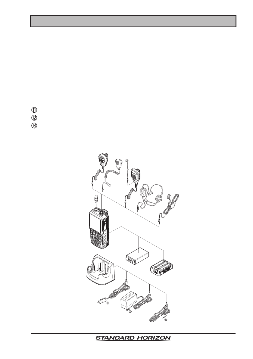
2 PACKING LIST
When the package containing the transceiver is rst opened, please check it
for the following contents:
HX870 Transceiver
CAT460 Antenna
SBR-13LI 7.4V 1800mAh Li-ion Battery Pack
SBH-12 Charger Cradle for HX870
SAD-11B 120VAC Wall Charger for SBH-12
E-DC-19A DC Cable with 12 V Cigarette Lighter Plug for SBH-12
SBT-13 Alkaline Battery Case for AAA x 5
Clip-22 Belt Clip
YS-05-01 Hand Strap
T9101606 USB Cable (Type USB “A” plug to Type USB mini “B” plug)
Owner’s Manual
Page 7HX870
3 OPTIONAL ACCESSORIES
MH-73A4B ...............................................Submersible Speaker/Microphone
MH-57A4B ............................................................ Mini Speaker/Microphone
SSM-14A .............. Submersible Speaker/Microphone with Earphone Jack
SEP-10 ................................................................... Earphone for SSM-14A
VC-24 ....................................................................................VOX Headset
SSM-55A ................................................................... Earpiece/Microphone
CN-3 ....................................................... Radio-to-Ship’s-Antenna Adapter
SBR-13 LI ............................................7.4V 1800mAh Li-ion Battery Pack
SBT-13 ...............................................Alkaline Battery Case (AAA x 5 pcs)
SBH-12 ............................................................................... Charger Cradle
E-DC-19A .................................DC Cable with 12 V Cigarette Lighter Plug
SAD-11B/C/U
.............................................. Wall Charger for the SBH-12
E-DC-6 ......................................................... DC Cable; plug and wire only
:
“B” sufx is for use with 120 VAC (Type-A plug), “C” sufx is for use with 230
VAC (Type-C plug), and “U” sufx is for use with 230 VAC (Type-BF plug).

Page 8
HX870
4 ONLINE WARRANTY REGISTRATION
(in USA or Canada only)
Please visit www.standardhorizon.com to register the HX870 Marine VHF. It
should be noted that visiting the website from time to time may be benecial
to you, as new products are released they will appear on the STANDARD
HORIZON website.
PRODUCT SUPPORT INQUIRIES
If you have any questions or comments regarding the use of the HX870, you
can visit the STANDARD HORIZON website to send an E-Mail or contact the
Product Support team at (800) 767-2450 M-F 8:00-5:00 PST.

Page 9HX870
5 ABOUT THIS RADIO
5.1 PROHIBITED COMMUNICATIONS
The FCC prohibits the following communications:
• False distress or emergency messages:
• Messages to “any boat” except in emergencies and radio tests;
• Messages to or from a vessel on land;
• Transmission while on land;
• Obscene, indecent, or profane language (potential ne of $10,000).
5.2 ABOUT VHF RADIO
The radio frequencies used in the VHF marine band lie between 156 and 158
MHz with some shore stations available between 161 and 163 MHz. The marine
VHF band provides communications over distances that are essentially “line of
sight” (VHF signals do not travel well through objects such as buildings, hills
or trees). Actual transmission range depends much more on antenna type,
gain and height than on the power output of the transmitter. On a xed mount
25W radio transmission expected distances can be greater than 15 miles, for
a portable 6W radio transmission the expected distance can be greater than
5 miles in “line of sight”.
5.3 DISTRESS AND HAILING (CHANNEL 16)
Channel 16 is known as the Hail and Distress Channel. An emergency may
be dened as a threat to life or property. In such instances, be sure the
transceiver is on and set to CHANNEL 16. Then use the following procedure:
1. Press the PTT (Push-To-Talk) button and say “Mayday, Mayday, Mayday.
This is , , ” (your vessel’s name).
2. Then repeat once: “Mayday, ” (your vessel’s name).
3. Now report your position in latitude/longitude, or by giving a true or magnetic
bearing (state which) to a well-known landmark such as a navigation aid
or geographic feature such as an island or harbor entry.
4. Explain the nature of your distress (sinking, collision, aground, re, heart
attack, life-threatening injury, etc.).
5. State the kind of assistance your desire (pumps, medical aid, etc.).
6. Report the number of persons aboard and condition of any injured.
7. Estimate the present seaworthiness and condition of your vessel.
8. Give your vessel’s description: length, design (power or sail), color and other
distinguishing marks. The total transmission should not exceed 1 minute.
9. End the message by saying “OVER”. Release the PTT button and listen.
10. If there is no answer, repeat the above procedure. If there is still no response,
try another channel.

Page 10
HX870
NOTE
The HX870 has the DSC Distress calling, that can transmit a distress
call digitally to all ships with compatible DSC radios. Refer to section
“10 DIGITAL SELECTIVE CALLING (DSC)”.
5.4 CALLING ANOTHER VESSEL (CHANNEL 16 OR 9)
Channel 16 may be used for initial contact (hailing) with another vessel.
However, its most important use is for emergency messages. This channel
must be monitored at all times except when actually using another channel.
It is monitored by the U.S. and Canadian Coast Guards and by other vessels.
Use of channel 16 for hailing must be limited to initial contact only. Call-
ing should not exceed 30 seconds, but may be repeated 3 times at 2-minute
intervals. In areas of heavy radio trafc, congestion on channel 16 resulting
from its use as a hailing channel can be reduced signicantly in U.S. waters
by using channel 9 as the initial contact (hailing) channel for non-emergency
communications. Here, also, calling time should not exceed 30 seconds but
may be repeated 3 times at 2-minute intervals.
Prior to making contact with another vessel, refer to the channel charts in this
manual, and select an appropriate channel for communications after initial
contact. For example, Channels 68 and 69 of the U.S. VHF Charts are some
of the channels available to non-commercial (recreational) boaters. Monitor
your desired channel in advance to make sure you will not be interrupting
other trafc, and then go back to either channel 16 or 9 for your initial contact.
When the hailing channel (16 or 9) is clear, press the PTT button and state the
name of the other vessel you wish to call and then “this is” followed by the
name of your vessel and your Station License (Call Sign) then release the PTT
button. When the other vessel returns your call, immediately request another
channel by pressing the PTT button and saying “go to”, the number of the
other channel, say “over” and release the PTT button. Then switch to the new
channel. When the new channel is not busy, call the other vessel.
After a transmission, say “over”, and release the PTT button. When all commu-
nication with the other vessel is completed, end the last transmission by stating
your Call Sign and the word “out”. Note that it is not necessary to state your
Call Sign with each transmission, only at the beginning and end of the contact.
Remember to return to Channel 16 when not using another channel. Some
radios automatically monitor Channel 16 even when set to other channels or
when scanning.

Page 11HX870
5.5 MAKING TELEPHONE CALLS
To make a radiotelephone call, use a channel designated for this purpose.
The fastest way to learn which channels are used for radiotelephone trafc
is to ask at a local marina. Channels available for such trafc are designated
Public Correspondence channels on the channel charts in this manual. Some
examples for USA use are Channels 24, 25, 26, 27, 28, 84, 85, 86, and 87. Call
the marine operator and identify yourself by your vessel’s name. The marine
operator will then ask you how you will pay for the call (telephone credit card,
collect, etc.) and then link your radio transmission to the telephone lines.
The marine telephone company managing the VHF channel you are using may
charge a link-up fee in addition to the cost of the call.
5.6 BRIDGE CHANNELS 13 AND 67
Channel 13 is used at docks, bridges and by vessels maneuvering in port.
Messages on this channel must concern navigation only, such as meeting and
passing in restricted waters.
Channel 67 is used for navigational trafc between vessels.
By regulation, power is normally limited to 1 Watt on these channels. Your radio
is programmed to automatically reduce power to this limit on these channels.
However, in certain situations it may be necessary to temporarily use a higher
power. See Page 26 for means to temporarily override the low-power limit on
these two channels.

Page 12
HX870
5.7 AUTOMATED RADIO CHECK SERVICE
In areas across the country, Sea Tow offers boaters a way to conduct radio
checks. To use Sea Tow’s free Automated Radio Check service, simply tune
your VHF radio to the appropriate channel for your location and conduct a
radio check as you typically would. Upon releasing your radio’s microphone,
the system will play an automated message and relay your transmission back
to you, thereby letting you know how your signal will sound to other boaters.
The Automated Radio Check Service is currently available in the areas listed
below.
West Coast Sea Tow Newport/LA - Ch. 27
Sea Tow San Diego - Ch. 27
Northeast Sea Tow Portland-Midcoast (Maine) - Ch. 27
Sea Tow Boston - Ch. 27
Sea Tow South Shore (Mass.) - Ch. 28
Sea Tow Rhode Island - Ch. 24
Sea Tow Eastern Long Island - Ch. 27
Sea Tow Huntington (N.Y.) - Ch. 27
Sea Tow Manasquan (N.J.) - Ch. 28
Mid-Atlantic Sea Tow Northern Chesapeake (Md.) - Ch. 28
Sea Tow Central Chesapeake (Md.) - Ch. 27
Sea Tow Hampton Roads (Va.) - Ch. 28
North Carolina Sea Tow Wrightsville Beach - Ch. 28
Sea Tow Ocean Isle Beach - Ch. 28
Florida Sea Tow Sebastian - Ch. 28
Sea Tow Fort Lauderdale - Ch. 27
Sea Tow Charlotte Harbor - Ch. 24
Sea Tow Tampa Bay - Ch. 27
Sea Tow Horseshoe Beach - Ch. 27
Sea Tow Carrabelle/St. Marks - Ch. 27
Sea Tow Pensacola/Orange Beach (Ala.) - Ch. 27
Page 13HX870
6 GETTING STARTED
NOTE
Water resistance of the transceiver is assured only when the battery
cover is attached to the transceiver, DATA jack cover is locked and
MIC/SP cap is installed in the MIC/SP jack.
6.1 BATTERIES AND CHARGERS
If the radio has never been used, or its charge is depleted, it may be charged
by connecting the SBH-12 Charger Cradle with the SAD-11B battery charger,
as shown in the illustration. If 12V DC power is available, the E-DC-19A DC
Cable with 12 V Cigarette Lighter Plug or the optional E-DC-6 DC Cable may
be used for charging the battery. The SAD-11B, E-DC-19A and E-DC-6 will
charge a completely discharged SBR-13LI battery pack in about 3 hours.
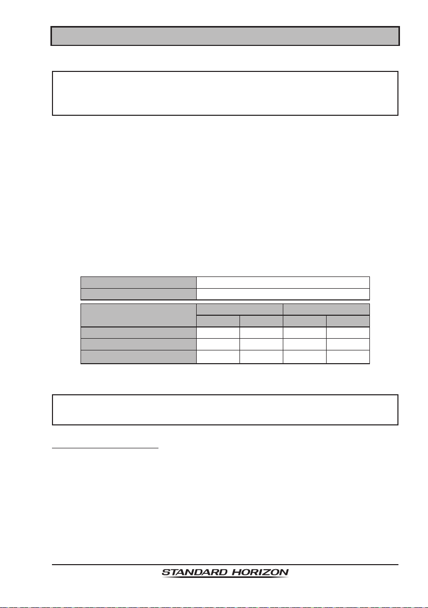
The SBR-13LI is a high performance Li-ion battery providing high capacity in
a compact package.
SBR-13LI Rechargeable Battery Pack
Capacity 1800 mAh
Nominal Voltage 7.4 V
Temperature Range
Minimum Maximum
°C °F °C °F
Charge 5 41 35 95
Discharge –20 –4 60 140
Storage
–10 14 35 95
CAUTION
To avoid risk of explosion and injury, SBR-13LI battery pack should only
be removed, charged or recharged in non-hazardous environments.
6.1.1 Battery Safety
Battery packs for your transceiver contain Li-ion batteries. This type of battery
stores a charge powerful enough to be dangerous if misused or abused,
especially when removed from the transceiver. Please observe the following
precautions:
DO NOT SHORT BATTERY PACK TERMINALS: Shorting the terminals that
power the transceiver can cause sparks, severe overheating, burns, and battery
cell damage. If the short is of sufcient duration, it is possible to melt battery
components. Do not place a loose battery pack on or near metal surfaces or

Page 14
HX870
objects such as paper clips, keys, tools, etc. When the battery pack is installed
on the transceiver, the terminals that transfer current to the transceiver are not
exposed. The terminals that are exposed on the battery pack when it is mounted
on the transceiver are charging terminals only and do not constitute a hazard.
DO NOT INCINERATE: Do not dispose of any battery in a re or incinerator. The
heat of re may cause battery cells to explode and/or release dangerous gases.
Battery Maintenance
For safe and proper battery use, please observe the following:
Battery packs should be charged only in non-hazardous environments.
Use only STANDARD HORIZON-approved batteries.
Use only a STANDARD HORIZON-approved charger. The use of any
other charger may cause permanent damage to the battery.
Follow charging instructions provided with the chargers.
Keep the battery contacts clean.
Battery Storage
Store the batteries in a cool place to maximize storage life. Since batteries are
subject to self-discharge, avoid high storage temperatures that cause large
self-discharge rates. After extended storage, a full recharge is recommended.
Battery Recycling
DO NOT PLACE USED BATTERIES IN YOUR REGULAR TRASH!
LI-ION BATTERIES MUST BE COLLECTED, RECYCLED OR DISPOSED
OF IN AN ENVIRONMENTALLY SOUND MANNER.
The incineration, land lling or mixing of Li-ion batteries with
the municipal solid waste stream is PROHIBITED BY LAW
in most areas.
Return batteries to an approved Li-ion battery recycler. This
may be where you purchased the battery.
Contact your local waste management ofcials for other
information regarding the environmentally sound collection,
recycling and disposal of Li-ion batteries.
Page 15HX870
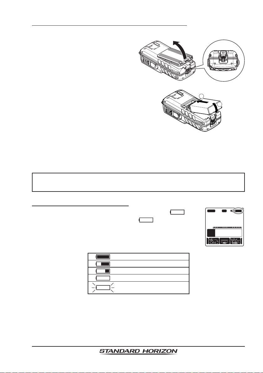
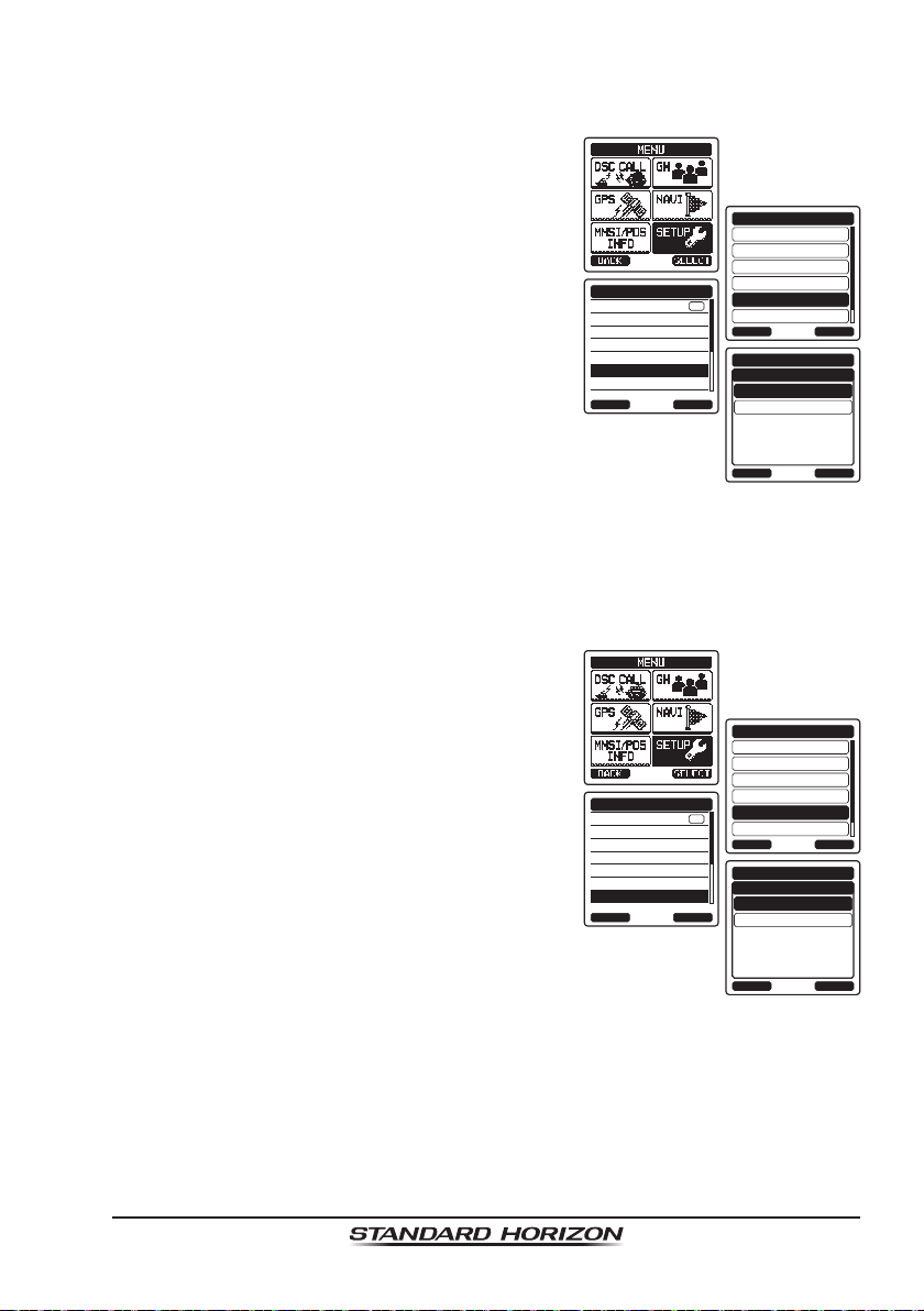
6.1.2 Rechargable Battery Installation/Removal
1. Turn the transceiver off.
2. Slide the battery cover lock
switch to the “UNLOCK” position,
then press “PUSH” to open the
battery cover.
3. Install the SBR-13LI battery pack
into the battery rest aligning it to
the battery contacts until it clicks.
4. Attach the battery cover, then
slide the battery cover lock switch
to the “LOCK” position.
2
1
To remove the battery pack, turn the transceiver off, open the battery cover,
then push and lift up the bottom end of the battery pack.
NOTE
The battery lock must be set to “LOCK” position to ensure water integrity
and keep the battery from coming loose.
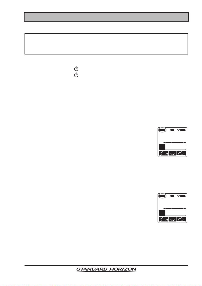
6.1.3 Battery Life Information
When the battery charge is almost depleted, a “
” icon
will appear on the display. When the “
” icon appears, it
is recommended that you charge the battery soon.
A
P
16
DISTRESS
VOL
118
°
09.582
33
°
37.120
W
s
LOC 09.56AM
BUSY HI
USA
TIME
LON
LAT
C
A
MEM
P-SET
: Full battery power
: Enough battery power
: Low battery power
: Poor battery power
: Charge (or replace) the battery
Page 16
HX870
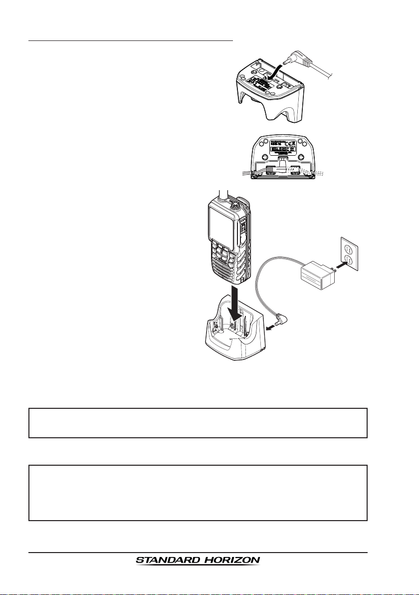
6.1.4 Using the SBH-12 Charger Cradle
1. Insert the DC plug from the
SAD-11B into the DC jack at the
bottom of the SBH-12.
Put the wire of the SAD-11B into
either of the left or right hook at
the bottom of the SBH-12.
2. Plug the SAD-11B into the AC
line outlet.
3. Insert the HX870 (with the battery
pack) into the SBH-12; the anten-
na should be at the left side when
viewing the charger from the
front.
If the HX870 is inserted correctly,
the HX870’s LCD display will
show the battery charging icon.
A fully-discharged pack will be
charged completely in approxi-
mately 3 hours.
When charging is completed, the battery charging icon will disappear.
CAUTION
The SBH-12 is NOT designed to be waterproof. Charge the radio in
a dry location.
NOTE
The SBH-12 is only designed for the charging of the HX870’s battery,
and is not suitable for other purposes. The SBH-12 may contribute
noise to TV and radio reception in the immediate vicinity, so we do not
recommend its use adjacent to such devices.
Page 17HX870
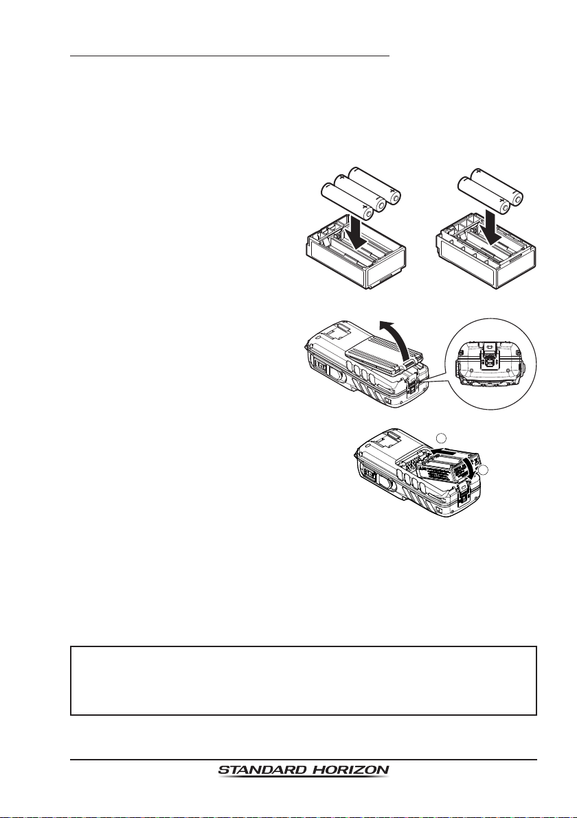
6.1.5 Installation of the SBT-13 Battery Case
The SBT-13 is a battery case that holds ve “AAA” size Alkaline batteries and
is used with the HX870 transceiver. The Alkaline batteries can be used for
reception and transmission in an emergency, and battery life will be shortened
dramatically.
1. Turn the transceiver off.
2. Slide the ve “AAA” size Alkaline
batteries into the SBT-13 with the
Negative (−) side of the batteries
touching the spring connections
inside the SBT-13.
Put three batteries into the
compartment on the front side
and two on the back side.
Front Back
3. Slide the battery cover lock
switch to the “UNLOCK” position,
then press “PUSH” to open the
battery cover.
4. Install the SBT-13 into the battery
rest aligning it to the battery
contacts until it clicks.
2
1
5. Attach the battery cover, then slide the battery cover lock switch to the
“LOCK” position.
To remove the battery case, turn the transceiver off, open the battery cover,
then push and lift up the bottom end of the battery case.
NOTE
• When the SBT-13 Alkaline Battery Case is used, the HX870 transmit
output is xed to 1 W.
• The HX870 will oat with the SBT-13 attached.
Page 18
HX870
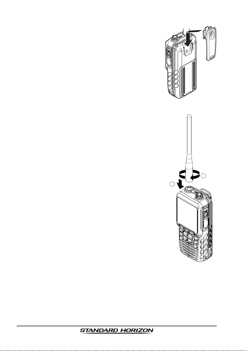
6.2 BELT CLIP INSTALLATION / REMOVAL
1. To install, align the Belt Clip Clip-22 to the groove of
the Battery pack, then press the Belt Clip downward
until it locks in place with a “Click”.
2. To remove, pull the Clip-22 tab away from the
battery pack to unlock the Clip-22, then slide the
Clip-22 upward to remove it.
6.3 ATTACHING AN ANTENNA
Insert the CAT460 antenna into the ANT jack at the top
panel, hold the bottom end of the antenna, then screw
it onto the mating connector on the transceiver until it
is snug. Do not over-tighten.
2
1

Page 19HX870
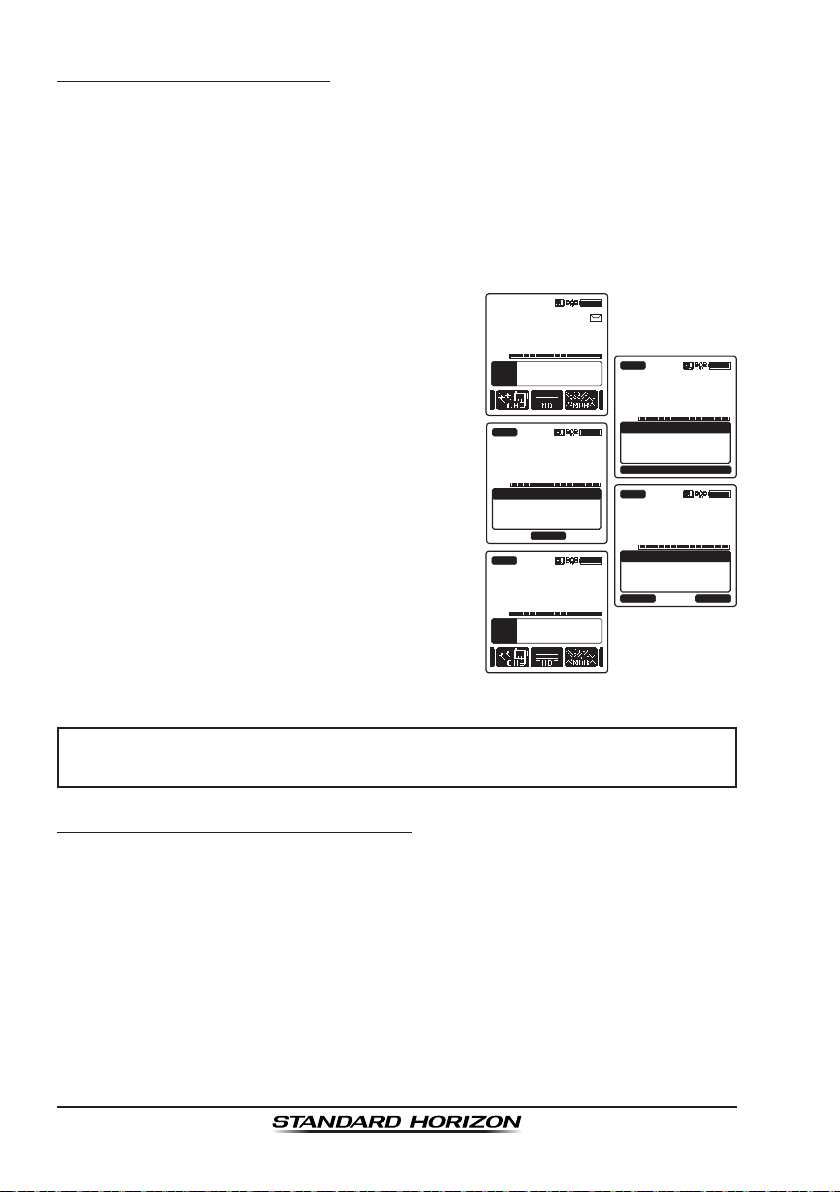
6.4 CHECKING GPS SIGNAL (GPS STATUS DISPLAY)
When the HX870 receives the GPS signal, a small satellite icon “ ” will
appear on the display and your current location (latitude/longitude) is shown
on the display.
The HX870 has a GPS status display which shows the
satellites currently being received, along with a graphi-
cal (bar-graph) representation of the relative signal
strengths from the satellites.
(GPS StatuS DiSPlay moDe)
HIUSA
LAT/LON
23
°
56.890E
123
°
56.890W
Oct/25 09:56AM
DATE
STATUS
FIX 3D
65
A
BUSY
1. Press and hold the POWER key on the left
side of the transceiver to turn it on.
GPS INFO
COMPASS
ENTER
GPS
GPS STATUS
BACK
HIUSA
LAT/LON
23
°
56.890S
123
°
56.890W
LOC 09:56AM
TIME
STATUS
SEARCH
65
A
BUSY
2. Press the MENU key to display “MENU”, then
select “GPS” with the CH▼/CH▲/◄/► key.
3. Press the [SELECT] soft key, then select
“GPS STATUS” with the CH▼/CH▲ key.
4. Press the [ENTER] soft key to display the
GPS status currently being received.
5. Press the CLR key to return to radio opera-
tion.
NOTE
• When the HX870 is rst turned on, it may take several minutes to
compute a x of your position. This is normal, as the HX870 is down-
loading “almanac” information from the GPS satellites.
• When using the HX870 inside of a cabin where GPS reception is limited,
choose a place where GPS satellite reception is good enough referring
to the GPS status display.

Page 20
HX870
6.5 CHANGING THE GPS TIME
From the factory the HX870 shows GPS satellite time or UTC (Universal Time
Coordinated) time. A time offset is needed to show the local time in your area.
The time offset must be changed in order for the radio to display the current
time in your area. See the Offset Time Table below.
offSet time table
1. Press the MENU key to display “MENU”, then
select “SETUP” with the CH▼/CH▲/◄/►
key.
DSC SETUP
GM SETUP
BACK
SETUP
WAYPOINT SETUP
CH SETUP
GPS SETUP
CONFIGURATION
SELECT
GPS ON/OFF
POWER SAVE
DIRECTION
LOCATION FORMAT
TIME OFFSET
TIME AREA
TIME FORMAT
GPS SETUP
BACK SELECT
ON
+09:00
BACK
GPS SETUP
+08:30
+08:00
+07:30
+07:00
ENTER
TIME OFFSET
2. Select “GPS SETUP” with the CH▼/CH▲ key.
3. Press the [SELECT] soft key, then select
“TIME OFFSET” with the CH▼/CH▲ key.
4. Press the [SELECT] soft key, then press the
CH▼/CH▲ key to select time offset of your
location. See illustration above to nd your
offset time. If “00:00” is assigned, the time
is the same as UTC or GPS satellite time.
5. Press the [ENTER] soft key to store the time
offset.
6. Press the CLR key to return to radio operation.
Page 21HX870
6.6 CHANGING THE TIME LOCATION
This menu selection allows the radio to show UTC time or local time with offset.
1. Press the MENU key to display “MENU”, then
select “SETUP” with the CH▼/CH▲/◄/►
key.
DSC SETUP
GM SETUP
BACK
SETUP
WAYPOINT SETUP
CH SETUP
GPS SETUP
CONFIGURATION
SELECT
GPS ON/OFF
POWER SAVE
DIRECTION
LOCATION FORMAT
TIME OFFSET
TIME AREA
TIME FORMAT
GPS SETUP
BACK SELECT
ON
UTC
BACK
GPS SETUP
LOCAL
ENTER
TIME AREA
2. Press the [SELECT] soft key, then select
“GPS SETUP” with the CH▼/CH▲ key.
3. Press the [SELECT] soft key, then press the
CH▼/CH▲ key to “TIME AREA”.
4. Press the [SELECT] soft key.
5. Press the CH▼/CH▲ key to select “UTC” or
“LOCAL”.
6. Press the [ENTER] soft key to store the
selected setting.
7. Press the CLR key to return to radio opera-
tion.
6.7 CHANGING THE TIME FORMAT
This menu selection allows the radio to setup to show time in 12-hour or
24-hour format.
1. Press the MENU key to display “MENU”, then
select “SETUP” with the CH▼/CH▲/◄/►
key.
DSC SETUP
GM SETUP
BACK
SETUP
WAYPOINT SETUP
CH SETUP
GPS SETUP
CONFIGURATION
SELECT
GPS ON/OFF
POWER SAVE
DIRECTION
LOCATION FORMAT
TIME OFFSET
TIME AREA
TIME FORMAT
GPS SETUP
BACK SELECT
ON
24hour
BACK
GPS SETUP
12hour
ENTER
TIME FORMAT
2. Press the [SELECT] soft key, then select
“GPS SETUP” with the CH▼/CH▲ key.
3. Press the [SELECT] soft key, then press the
CH▼/CH▲ key to select “TIME FORMAT”.
4. Press the [SELECT] soft key.
5. Press the CH▼/CH▲ key to select “12hour”
or “24hour”.
6. Press the [ENTER] soft key to store the
selected setting.
7. Press the CLR key to return to radio opera-
tion.

Page 22
HX870
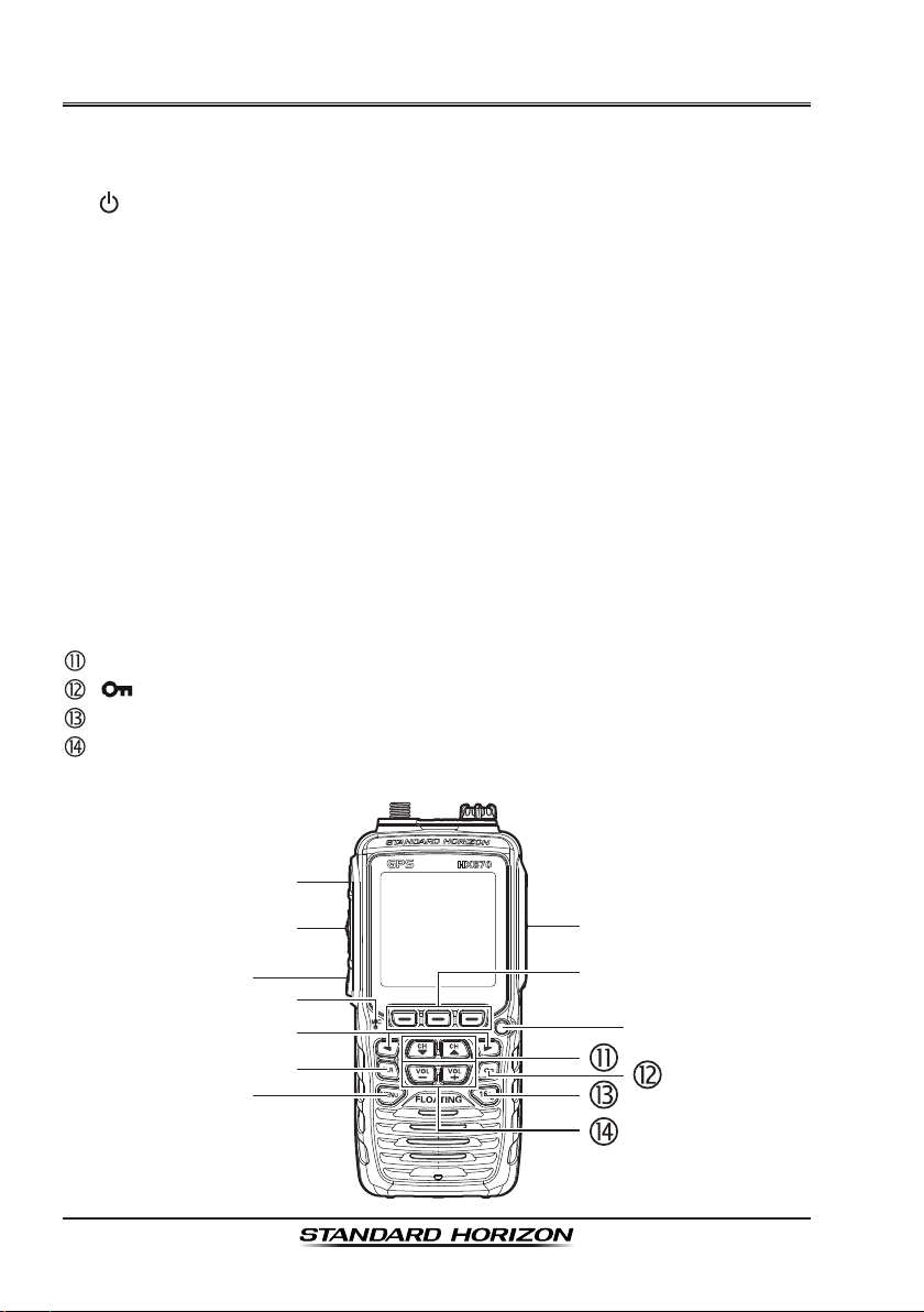
7 CONTROLS AND INDICATORS
This section denes each control of the transceiver. See illustration below for
location of controls. For detailed operating instructions refer to chapter 8 of
this manual.
NOTE
When transmitting, position
your mouth about 1/2 to 1
inch (1.2 ~ 2.5 cm) away
from the small mic hole.
Speak slowly and clearly
into the microphone.
ANT jack
(
Top side
)
The supplied CAT460 exible antenna is attached here.
(Power) switch (Left side)
Press and hold to toggle the radio on or off.
PTT (Push-To-Talk) button (Left side)
When pushed activates the transmitter.

Page 23HX870
SQL switch (Left side)
Press this key to activate the squelch adjusting mode. Press the CH▲ or
CH▼ key to adjust the squelch threshold level.
Press and hold the squelch key for 3 seconds to open the squelch, allow-
ing you to monitor the operating channel. Press this key to resume normal
(quiet) monitoring.
MIC hole
The internal microphone is located here.
NOTE
When transmitting, position your mouth about 1/2 to 1 inch (1.2 ~
2.5 cm) away from the small mic hole. Speak slowly and clearly
into the microphone.
Keypad
MENU key
Press to access MENU.
CH▲ key
This key is used to change the operating channel and squelch thresh-
old level.
Press the key momentarily, the channel (or level) increases one step.
Holding the key, the channel (or level) increases continuously.
CH▼ key
This key is used to change the operating channel and squelch thresh-
old level.
Press the key momentarily, the channel (or level) decreases one step.
Holding the key, the channel (or level) decreases continuously.
key
Hold down this key to lock the keypad so that they are not accidentally
changed. “LOCK” will appear on the entire screen, to indicate that the
functions are locked. Hold down this key until “UNLOCK” appears to
unlock the radio.
◄/► key
Press to toggle the on-screen menus to right/left.
VOL+ key
Press to increase the speaker audio volume level.

Page 24
HX870
VOL− key
Press to decrease the speaker audio volume level.
16/S key
Pressing this key immediately recalls channel 16 from any channel
location. Holding down this key recalls the SUB channel (The default
setting is channel 9). Pressing this key again reverts to the previous
selected working channel.
CLR key
Press this key to cancel a menu selection and/or keypad entry.
MIC/SP jack (Top side)
The jack accepts the optional MH-73A4B Submersible Speaker/Microphone,
MH-57A4B Mini Speaker/Microphone, VC-24 VOX Headset, SSM-10
Submersible Speaker/Microphone, or SSM-55A Earpiece/Microphone.
When this jack is used, the internal speaker and microphone are disabled.
DATA jack (Right side)
Use the USB mini type B jack to output the NMEA data, congure the
transceiver settings and download the GPS logger data.
DISTRESS
key (Right side)
Used to send a DSC Distress Call. To send the distress call, refer to section
“9.3.1 Transmitting a DSC Distress Call”.
Soft keys
The 3 programmable soft keys can be customized by the Setup Menu
mode described in section “12.7 SOFT KEYS”. When one of the soft keys
is pressed briey, the functions will appear above each key on the display.
Strobe light indicator
When the Emergency feature is activated, this indicator blinks the interna-
tionally-recognized Morse Code “S.O.S” message.
When the Water Hazard feature is activated, this indicator illuminates if the
transceiver is submerged.
Speaker
The internal speaker is located here.
Battery pack lock (Bottom side)
Turn the Battery Pack Lock to the “UNLOCK” position for battery removal.
Page 25HX870
8 BASIC OPERATION
NOTE
Before operating the HX870 for the rst time, it is recommended that
you fully charge the battery. See section “6.1.4 Using the SBH-12
Charger Cradle” for details.
8.1 TURNING ON AND OFF THE TRANSCEIVER
1. Press and hold the key on the left side of the radio to turn the radio on.
2. Press and hold the key again to turn the radio off.
8.2 RECEPTION
1. Press the SQL key, then press the CH▼ key until noise is heard from the
speaker. This state is known as “squelch off”.
2. Press the VOL−/VOL+ key until noise or audio from the speaker is at a
comfortable level.
3. Press the SQL key, then press the CH▲ key until the random noise disap-
pears. This state is known as the “squelch threshold”.
4. Press the CH▼/CH▲ key to select the desired channel.
Refer to the channel chart on Pages 125 to 127 for avail-
able channels.
5. When a message is received, adjust the volume to the
desired listening level. The “[BUSY]” indicator on the
display indicates that communications are being received.
A
P
16
DISTRESS
VOL
118
°
09.582
33
°
37.120
W
s
LOC 09.56AM
BUSY HI
USA
TIME
LON
LAT
C
A
MEM
P-SET
8.3 TRANSMISSION
1. Perform steps 1 through 4 of RECEPTION.
2. Before transmitting, monitor the channel to ensure it is clear.
THIS IS AN FCC REQUIREMENT!
3. Press the PTT (push-to-talk) button. The “[TX]” indicator
on the LCD is displayed.
4. Speak slowly and clearly into the MIC hole.
5. When the transmission is nished, release the PTT button.
A
P
16
DISTRESS
VOL
118
°
09.582
33
°
37.120
W
s
LOC 09.56AM
TX HI
USA
TIME
LON
LAT
C
A
MEM
P-SET
Page 26
HX870
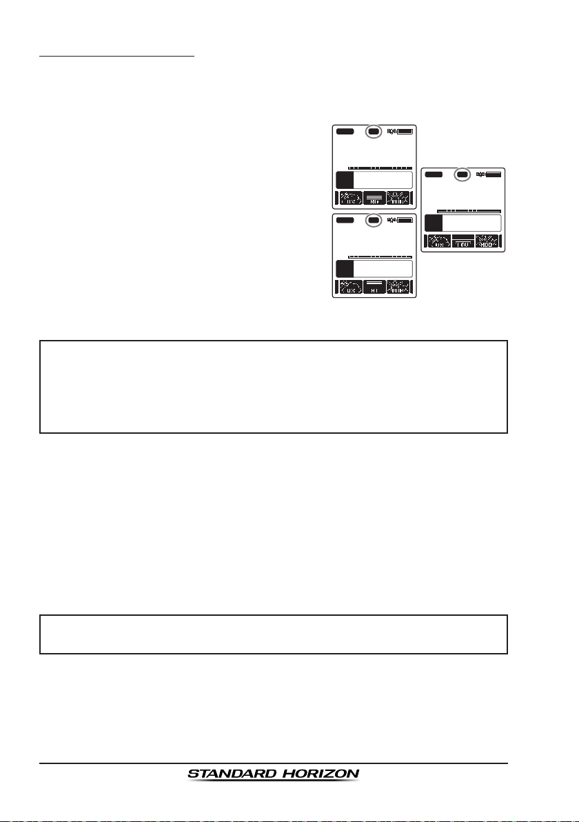
8.3.1 Transmit Power
The TX output power of the HX870 is set to high level (6W) in factory default,
and the “[HI]” indicator is displayed on the top part of the screen.
To switch the TX output power:
1. Press ◄/► key repeatedly until the [HI],
[MD], or [LOW] soft key is displayed at the
bottom of the screen.
A
P
16
DISTRESS
VOL
118
°
09.582
33
°
37.120
W
s
LOC 09.56AM
TX HI
USA
TIME
LON
LAT
C
A
MEM
P-SET
A
P
16
DISTRESS
VOL
118
°
09.582
33
°
37.120
W
s
LOC 09.56AM
TX MD
USA
TIME
LON
LAT
C
A
MEM
P-SET
A
P
16
DISTRESS
VOL
118
°
09.582
33
°
37.120
W
s
LOC 09.56AM
TX LO
USA
TIME
LON
LAT
C
A
MEM
P-SET
2. Press the [HI], [MD], or [LOW] soft key to
switch between HI (6W), MD (2W), or LO
(1W) output power.
NOTE
• When the SBT-13 Alkaline Battery Case is used, only the low power
(1W) can be set.
• Depending on the remaining power of the SBR-13LI Battery Pack, the
HX870 may transmit with the medium or low power even though the
“[HI]” indicator is displayed.
8.4 TRANSMIT TIME-OUT TIMER (TOT)
When the PTT button is held down, transmit time is limited to 5 minutes. This
limits unintentional transmissions due to a stuck microphone. About 10 seconds
before automatic transmitter shutdown, a warning beep will be heard from the
speaker(s). The transceiver will automatically go to receive mode, even if the
PTT button is continually held down. Before transmitting again, the PTT button
must rst be released and then pressed again.
NOTE
Once the transmitter is shut down by the TOT, transmission to the last
channel is only allowed 10 seconds after the shutdown.
Page 27HX870
8.5 SIMPLEX/DUPLEX CHANNEL USE
Refer to the VHF MARINE CHANNEL CHART (Pages 125 to 127) for instruc-
tions on use of simplex and duplex channels.
NOTE
All channels are factory-programmed in accordance with FCC (USA),
Industry Canada (Canada), and International regulations. Mode of
operation cannot be altered from simplex to duplex or vice-versa.
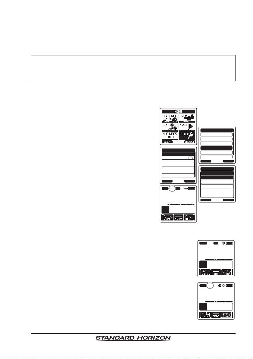
8.6 USA, INTERNATIONAL, AND CANADA MODE
To change the channel group from USA to International or Canada:
1. Press the MENU key to display “MENU”, then
select “SETUP” with the CH▼/CH▲/◄/►
key.
DSC SETUP
GM SETUP
BACK
SETUP
WAYPOINT SETUP
CH SETUP
GPS SETUP
CONFIGURATION
SELECT
CH GROUP
WX ALERT
SCAN MEMORY
SCAN TYPE
SCAN RESUME
MULTI WATCH
PRIORITY CH
CH SETUP
BACK SELECT
ON
USA
BACK
CH SETUP
INTL
CAN
ENTER
CH GROUP
A
P
16
DISTRESS
VOL
118
°
09.582
33
°
37.120
W
s
LOC 09.56AM
TX HI
USA
TIME
LON
LAT
C
A
MEM
P-SET
2. Press the [SELECT] soft key, then press the
CH▼/CH▲ key to select “CH SETUP”.
3. Press the [SELECT] soft key, then press the
CH▼/CH▲ key to select “CH GROUP”.
4. Press the [SELECT] soft key.
5. Press the CH▼/CH▲ key to select desired
channel group “USA”, “INTL”, or “CAN”.
6. Press the [ENTER] soft key to store the
selected setting.
7. Press the CLR key to return to radio opera-
tion.
8.7 NOAA WEATHER CHANNELS
1. To receive a NOAA weather channel, press ◄/► key
repeatedly until the [WX] soft key is displayed at the bottom
of the screen.
A
P
16
DISTRESS
VOL
118
°
09.582
33
°
37.120
W
s
LOC 09.56AM
BUSY HI
USA
TIME
LON
LAT
C
A
MEM
P-SET
07
162.525MHz
VOL
118
°
09.582
33
°
37.120
W
s
LOC 09.56AM
BUSY
WX
TIME
LON
LAT
2. Press the [WX] soft key. The “WX” indicator appears on
the top part of the screen.
3. Press the CH▼/CH▲ key to select a different NOAA
weather channel.
4. To exit from the NOAA weather channels, press the [CH]
soft key. The transceiver returns to the channel it was on
prior to a weather channel and the “WX” indicator disap-
pears from the display.
Page 28
HX870
8.7.1 NOAA Weather Alert
In the event of extreme weather disturbances, such as storms and hurricanes,
the NOAA (National Oceanic and Atmospheric Administration) sends a weather
alert accompanied by a 1050 Hz tone and subsequent weather report on one
of the NOAA weather channels.
The HX870 can receive weather alerts when monitoring a weather channel
and, on the last selected weather channel during scanning modes or while on
another working channel.
When an alert is received on a NOAA weather
channel, scanning will stop and the transceiver
will emit a loud beep to alert the user of a NOAA
broadcast. Press any key to stop the alert.
After stopping the beep sound, the weather
alert reception conrmation screen will appear.
Press [OK] to display a conrmation screen.
The conrmation screen will ask you whether
to move to the weather channel or return in the
marine channel. Press [YES] to switch to the
weather channel, and press [NO] to return to
the marine channel.
To disable the weather alert function, refer to
section “14.2 WEATHER ALERT”.
07
162.525MHz
VOL
118
°
09.582
33
°
37.120
W
s
LOC 09.56AM
WX
TIME
LON
LAT
10
163.275MHz
VOL
BUSY
WX
!Warning!
Radio received
Weather Alert!
Press any key
10
163.275MHz
VOL
BUSY
WX
!Warning!
Radio received
Weather Alert!
OK
10
163.275MHz
VOL
BUSY
WX
!Warning!
Do you want to
change the CH?
YES NO
10
163.275MHz
VOL
118
°
09.582
33
°
37.120
W
s
LOC 09.56AM
BUSY
WX
TIME
LON
LAT
NOTE
If no key is pressed the alert will sound for 5 minutes and then the
weather report will be received.
8.7.2 NOAA Weather Alert Testing
NOAA tests the alert system ever Wednesday between 11AM and 1PM. To
test the HX870’s NOAA weather feature, setup as in section “8.7.1 NOAA
Weather Alert” and conrm the alert is heard on Wednesdays between 11AM
and 1PM local time.

Page 29HX870
8.8 MULTI WATCH (TO PRIORITY CHANNEL)
Multi watch is used to scan two or three channels for communications.
In Dual Watch, a normal VHF channel and the priority channel are scanned
alternately.
In Triple Watch, a normal VHF channel, the priority channel, and the sub
channel are scanned alternately.
When a signal is received on the normal channel the radio briey switches
between the normal channel and the priority channel to look for a transmission.
If the radio receives communications on the priority channel the radio stops
and listens to priority channel until communication ends and then starts dual
or triple watch scan again.
8.8.1 Setting up the Multi Watch Operation
1. Press the MENU key to display “MENU”, then
select “SETUP” with the CH▼/CH▲/◄/►
key.
DSC SETUP
GM SETUP
BACK
SETUP
WAYPOINT SETUP
CH SETUP
GPS SETUP
CONFIGURATION
SELECT
CH GROUP
WX ALERT
SCAN MEMORY
SCAN TYPE
SCAN RESUME
MULTI WATCH
PRIORITY CH
CH SETUP
BACK SELECT
ON
DUAL
BACK
CH SETUP
TRIPLE
ENTER
MULTI WATCH
2. Press the [SELECT] soft key, then press the
CH▼/CH▲/◄/► key to select “CH SETUP”.
3. Press the [SELECT] soft key, then select
“MULTI WATCH” with the CH▼/CH▲ key.
4. Press the [SELECT] soft key.
5. Press the CH▼/CH▲ key to select “DUAL”
or “TRIPLE”.
6. Press the [ENTER] soft key to store the
selected setting.
7.
Press the CLR key to return to radio operation.
8.8.2 Starting the Dual Watch
1. Press the SQL key, then press the CH▼/CH▲ key until the background
noise disappears.
2. Press the CH▼/CH▲ key to select a channel you wish to watch.
3. Press ◄/► key repeatedly until the [Dual Watch] soft key
is displayed at the bottom of the screen, press the [DUAL
WATCH] soft key.
A
22
USCG
DW
16
VOL
118
°
09.582
33
°
37.120
W
s
LOC 09.56AM
BUSY HI
USA
TIME
LON
LAT
C
A
MEM
P-SET
The radio will monitor the priority channel and the channel
that was selected in step 2.
If a signal is received on the channel selected in step 2,
the HX870 will dual watch to priority channel.
4. To stop dual watch, press one of the soft keys, then press the [DUAL
WATCH] soft key again.

Page 30
HX870
When selecting “TRIPLE” in the SETUP menu, [TRIPLE WATCH] will be
displayed as the soft key instead of [DUAL WATCH].
NOTE
The priority channel may be changed from CH16 (default) to another
channel. Refer to section “14.7 PRIORITY CHANNEL”.
8.9 SCANNING
The HX870 will automatically scan channels programmed into the preset
channel memory and also the scan channel memory, and the last selected
weather channel.
When an incoming signal is detected on one of the channels during scan, the
radio will pause on that channel, allowing you to listen to the incoming transmis-
sion. The radio will automatically start scanning again after the transmission
stops.
8.9.1 Selecting the Scan Type
1. Press the MENU key to display “MENU”, then
select “SETUP” with the CH▼/CH▲/◄/►
key.
DSC SETUP
GM SETUP
BACK
SETUP
WAYPOINT SETUP
CH SETUP
GPS SETUP
CONFIGURATION
SELECT
CH GROUP
WX ALERT
SCAN MEMORY
SCAN TYPE
SCAN RESUME
MULTI WATCH
PRIORITY CH
CH SETUP
BACK SELECT
ON
PRIORITY
BACK
CH SETUP
MEMORY
ENTER
SCAN TYPE
2. Press the [SELECT] soft key, then press the
CH▼/CH▲/◄/► key to select “CH SETUP”.
3. Press the [SELECT] soft key, then select
“SCAN TYPE” with the CH▼/CH▲ key.
4. Press the [SELECT] soft key.
5. Press the CH▼/CH▲ key to select “PRIOR-
ITY” or “MEMORY”.
6. Press the [ENTER] soft key to store the
selected setting.
7. Press the CLR key to return to radio opera-
tion.
MeMory Scan
(
M-Scan
)
CH12
CH09
CH01A
CH15
CH18
CH22A
CH61A
CH68A
CH68A
CH88A
Priority Scan
(
P-Scan
)
Priority Channel
CH12
CH09
CH01A
CH15
CH18
CH22A
CH61A
CH68A
CH68A
CH88A
 Loading...