


HX290
Floating Marine Transceiver
Owner’s Manual
HX290 |
Page 1 |
|
|

TABLE OF CONTENTS
QUICK REFERENCE GUIDE........................................................................................................ |
3 |
|||
1. |
GENERAL INFORMATION .................................................................................................... |
4 |
||
|
1.1 |
INTRODUCTION ......................................................................................................... |
4 |
|
|
4.2 |
RF EXPOSURE SAFETY STATEMENT ................................................................... |
4 |
|
2. |
ACCESSORIES ...................................................................................................................... |
5 |
||
|
2.1 |
PACKING LIST ........................................................................................................... |
5 |
|
|
2.2 |
OPTIONS ..................................................................................................................... |
5 |
|
3. |
ABOUT THIS RADIO ............................................................................................................ |
6 |
||
|
3.1 |
ABOUT THE VHF MARINE BAND .......................................................................... |
6 |
|
|
3.2 |
ABOUT WATER RESISTANCE ................................................................................. |
6 |
|
|
3.3 |
DISTRESS AND HAILLING (CHANNEL 16) ............................................................ |
6 |
|
|
3.4 |
CALLING ANOTHER VESSEL (CHANNEL 16 OR 9) ............................................ |
7 |
|
|
3.5 |
OPERATING ON CHANNEL 13 ............................................................................... |
8 |
|
|
3.6 |
OPERATING ON CHANNEL 67 ............................................................................... |
8 |
|
|
3.7 |
SIMPLEX/DUPLEX CHANNEL USE ......................................................................... |
8 |
|
4. |
GETTING STARTED ............................................................................................................ |
10 |
||
|
4.1 |
RADIO CARE ............................................................................................................ |
10 |
|
|
4.2 |
BELT CLIP, HAND STRAP INSTALLATION AND REMOVAL ............................. |
10 |
|
|
4.3 |
BATTERIES AND CHARGERS ............................................................................... |
11 |
|
|
|
4.3.1 |
BATTERY SAFETY ....................................................................................... |
11 |
|
|
4.3.2 BATTERY INSTALLATION / REMOVAL ....................................................... |
12 |
|
|
|
4.3.3 |
BATTERY CHARGING ................................................................................. |
13 |
5. |
CONTROLS AND INDICATORS ......................................................................................... |
14 |
||
|
5.1 |
CONTROLS AND SWITCHES ................................................................................ |
14 |
|
|
5.2 |
LCD INDICATORS .................................................................................................... |
17 |
|
6. |
BASIC OPERATION ............................................................................................................ |
18 |
||
|
6.1 |
PROHIBITED COMMUNICATIONS ......................................................................... |
18 |
|
|
6.2 |
INITIAL SETUP ......................................................................................................... |
18 |
|
|
6.3 |
RECEPTION .............................................................................................................. |
18 |
|
|
6.4 |
TRANSMISSION ....................................................................................................... |
19 |
|
|
|
6.4.1 |
TRANSMIT TIME-OUT TIMER (TOT)........................................................... |
19 |
|
6.5 |
USA, CANADA, AND INTERNATIONAL CHANNELS .............................................. |
20 |
|
|
6.6 |
KEYPAD LOCKING .................................................................................................. |
20 |
|
|
6.7 |
NOAA WEATHER CHANNELS ............................................................................... |
21 |
|
|
|
6.7.1 |
NOAA WEATHER ALERT ............................................................................. |
21 |
|
|
6.7.2 NOAA WEATHER ALERT TESTING ............................................................ |
21 |
|
|
6.8 |
PRESET CHANNELS (0 ~ 9): INSTANT ACCESS ................................................ |
22 |
|
|
|
6.8.1 |
PROGRAMMING .......................................................................................... |
22 |
|
|
6.8.2 |
OPERATION ................................................................................................. |
22 |
|
6.9 |
SCANNING ................................................................................................................ |
23 |
|
|
|
6.9.1 SELECTING THE SCAN TYPE .................................................................... |
23 |
|
|
|
6.9.2 |
PROGRAMMING SCAN MEMORY ............................................................ |
24 |
|
|
6.9.3 |
MEMORY SCANNING (M-SCAN) ................................................................ |
24 |
|
|
6.9.4 |
PRIORITY SCANNING (P-SCAN) ................................................................ |
24 |
|
6.10 |
DUAL WATCH ........................................................................................................... |
25 |
|
7. |
MENU (“SET”) MODE .......................................................................................................... |
26 |
||
8. |
MAINTENANCE .................................................................................................................... |
28 |
||
|
8.1 |
GENERAL .................................................................................................................. |
28 |
|
|
8.2 |
REPLACEMENT PARTS .......................................................................................... |
28 |
|
|
8.3 |
TROUBLESHOOTING CHART ................................................................................ |
29 |
|
9. |
VHF MARINE CHANNEL ASSIGNMENT .......................................................................... |
30 |
||
10. WARRANTY .......................................................................................................................... |
|
36 |
||
11. |
INSTALLATION OF OPTION .............................................................................................. |
39 |
||
|
11.1 |
FBA-42 ALKALINE BATTERY CASE ........................................................................ |
39 |
|
12. SPECIFICATIONS ................................................................................................................. |
40 |
|||
|
12.1 |
GENERAL .................................................................................................................. |
40 |
|
|
12.2 |
TRANSMITTER ......................................................................................................... |
40 |
|
|
12.3 |
RECEIVER ................................................................................................................ |
40 |
|
13. |
FCC & CANADA RADIO LICENSE INFORMATION ....................................................... |
41 |
||
14. |
FCC NOTICE |
....................................................................................................................... |
42 |
|
Page 2 |
|
HX290 |
|
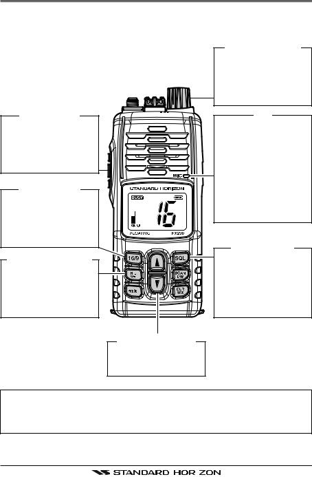
QUICK REFERENCE GUIDE
This transceiver is equipped with the E2O (Easy-To-Operate) system. You can do the basic operation in numerical order of the illustration below.
[PWR/VOL] KNOB
[PTT] SWITCH
Speak into the microphone in a normal voice level while pressing this switch.
[16/9] BUTTON
Press to recall channel 16.
Press and hold to recall channel 9.
[H/L( )] BUTTON
Press to toggle the transmit power between High (5W) and Low (1W).
[ ]/[ ] BUTTONS
Selects the operating channel.
Rotate this knob clockwise to turn on the radio, and adjust the audio level.
MIC
When transmitting, position your mouth 1 inch (2.5 cm) away from the small mic hole.
Speak slowly and clearly into the microphone.
[SQL] BUTTON
Press this key first, then press the [ ] key to squelch or press the [ ] key to un-squelch the radio.
NOTE
For additional details, refer to next page or section “5. CONTROLS AND
INDICATORS”.
HX290 |
|
Page 3 |
|

1.GENERAL INFORMATION
1.1INTRODUCTION
Congratulations on your purchase of the HX290! The HX290 is a JIS-8/IPX8
Submersible Floating 5-Watt portable two way marine transceiver. The transceiver has all allocated USA, International, or Canadian channels. It has emergency channel 16 which can be immediately selected from any channel by pressing the  key. NOAA (National Oceanic and Atmospheric Administration) Weather channels can also be accessed immediately by pressing and holding the
  key.
key.
The HX290 includes the following features: 10 Programmable Preset Channels, Memory, Priority, Dual Watch Scanning, NOAA Weather Alert, easy-to- read large LCD display, EEPROM memory back-up, Battery Life displayed on LCD, Glow-In-The-Dark strip, and a transmit Time-Out Timer (TOT).
The HX290 transmitter provides a full 5 Watt of transmit power and also is selectable to 1 Watt to assist the user in ensuring maximum battery life.
JIS-8/IPX8: 1.5 m (about 5Ft) for 30 minutes
1.2 RF EXPOSURE SAFETY STATEMENT
Your wireless handheld portable transceiver contains a low power transmitter.
When the Push-to-Talk (PTT) button is pushed, the transceiver sends out radio frequency (RF) signals. In August 1996, the Federal Communications Commission adopted RF exposure guidelines with safety levels for hand-held wireless devices.
This device is authorized to operate at a duty factor not to exceed 50% (this corresponds to 50% transmission time and 50% reception time).
WARNING: To maintain compliance with the FCC’s RF exposure guidelines, this transmitter and its antenna must maintain a separation distance of at least
1 inch (2.5 centimeters) from your face. Speak in a normal voice, with the antenna pointed up and away from the face at the required separation distance.
Use only the supplied antenna. Unauthorized antennas, modifications, or attachments could damage the transmitter, and may violate FCC regulations.
Page 4 |
|
HX290 |
|
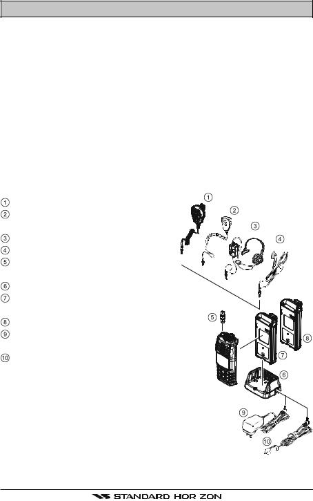
2.ACCESSORIES
2.1PACKING LIST
When the package containing the transceiver is first opened, please check it for the following contents:
HX290 Transceiver
CAT460 Antenna
FNB-110LI 7.4 V, 1170 mAh Li-Ion Battery Pack
CD-52 Charger Cradle for HX290
PA-44B 120VAC Wall Charger for CD-52
E-DC-19A DC Cable with 12 V Cigarette Lighter Plug
CLIP-22 Belt Clip
Hand Strap
Owner’s Manual
2.2OPTIONS
MH-73A4B |
Speaker/Microphone |
|
||||
MH-57A4B |
Mini Speaker/Micro- |
|
||||
|
phone |
|
||||
VC-24 |
VOX Headset |
|
||||
VC-27 |
Earpiece/Microphone |
|
||||
CN-3 |
Radio-to-Ship’s Antenna |
|
|
|
|
|
|
|
|||||
|
Adapter |
|
|
|
||
|
|
|
||||
CD-52 |
Charger Cradle |
|
||||
|
||||||
FNB-110LI |
7.4 V, 1170 mAh Li-Ion |
|
||||
|
Battery Pack |
|
||||
FBA-42 |
Alkaline Battery Case |
|
||||
PA-44B/C/U AC Wall Charger for the |
|
|||||
|
||||||
|
CD-52 |
|
||||
E-DC-19A |
DC Cable with 12 V Ciga- |
|
||||
|
rette Lighter Plug |
|
||||
: “B” suffix is for use with 120 VAC (Type-A plug), “C” suffix is for use with 230 VAC
(Type-C plug), and “U” suffix is for use with 230 VAC (Type-BF plug).
Note: Before operating the HX290 for the first time, it is recommended that the battery
be charged. Please see section “4.3.3 BATTERY CHARGING” for details.
HX290 |
|
Page 5 |
|

3. ABOUT THIS RADIO
3.1 ABOUT THE VHF MARINE BAND
The radio frequencies used in the VHF marine band lie between 156 and 162
MHz. The marine VHF band provides communications over distances that are essentially “Line of sight” Actual transmission range depends much more on antenna type, gain and height than on the power output of the transmitter. On a fixed mount 25 W radio transmission expected distances can be greater than 15 miles, for a portable 5 W radio transmission the expected distance can be greater than 5 miles in “Line of sight”.
The user of a Marine VHF radio is subject to severe fines if the radio is used on land. The reasoning for this is you may be near an inland waterway, or propagation anomalies may cause your transmission to be heard in a waterway. If this occurs, depending upon the marine VHF channel on which you are transmitting, you could interfere with a search and rescue case, or contribute to a collision between passing ships. For VHF Marine channel assignments refer to section “9”.
WARNING
This radio is capable of transmitting on Marine VHF.
The FCC allows the use of VHF Marine band on water areas only. However the FCC does not allow the use of the VHF Marine band when on land. If persons use the VHF Marine Band on land and interfere with others communicating, the FCC will be notified and search for the interference. Responsible parties found to be transmitting on the VHF Marine Band on land could be fined up to $10,000 for the first offense.
3.2 ABOUT WATER RESISTANCE
Water resistance of the transceiver is ensured only when the battery pack is attached to the transceiver and MIC/SP cap is installed in the MIC/SP jack.
3.3 DISTRESS AND HAILLING (CHANNEL 16)
Channel 16 is known as the Hail and Distress Channel. An emergency may be defined as a threat to life or property. In such instances, be sure the transceiver is on and set to “Channel 16”. Then use the following procedure:
1.Press the PTT (Push-To-Talk:  ) switch and say “Mayday, Mayday, Mayday. This is _____, _____, _____” (your vessel’s name).
2.Then repeat once: “Mayday, _____” (your vessel’s name).
3.Now report your position in latitude/longitude, or by giving a true or magnetic bearing (state which) to a well-known landmark such as a navigation
Page 6 |
|
HX290 |
|

aid or geographic feature such as an island or harbor entry.
4.Explain the nature of your distress (sinking, collision, aground, fire, heart attack, life-threatening injury, etc.).
5.State the kind of assistance your desire (pumps, medical aid, etc.).
6.Report the number of persons aboard and condition of any injured.
7.Estimate the present seaworthiness and condition of your vessel.
8.Give your vessel’s description: length, design (power or sail), color and other distinguishing marks. The total transmission should not exceed 1 minute.
9.End the message by saying “OVER”. Release the PTT ( ) switch and listen.
10.If there is no answer, repeat the above procedure. If there is still no response, try another channel.
3.4 CALLING ANOTHER VESSEL (CHANNEL 16 OR 9)
Channel 16 may be used for initial contact (hailing) with another vessel.
However, its most important use is for emergency messages. This channel must be monitored at all times except when actually using another channel.
It is monitored by the U.S. and Canadian Coast Guards and by other vessels.
Use of channel 16 for hailing must be limited to initial contact only. Calling should not exceed 30 seconds, but may be repeated 3 times at 2-minute intervals. In areas of heavy radio traffic, congestion on channel 16 resulting from its use as a hailing channel can be reduced significantly in U.S. waters by using
Channel 9 as the initial contact (hailing) channel for non-emergency communications. Also hailing on channel 9, the calling time should not exceed 30 seconds but may be repeated 3 times at 2-minute intervals.
Prior to making contact with another vessel, refer to the channel charts in this manual, and select an appropriate channel for communications after initial contact. For example, Channels 68 and 69 of the U.S. VHF Charts are some of the channels available to non-commercial (recreational) boaters. Monitor your desired channel in advance to make sure you will not be interrupting other traffic, and then go back to either channel 16 or 9 for your initial contact.
When the hailing channel (16 or 9) is clear, state the name of the other vessel you wish to call and then “this is” followed by the name of your vessel and your Station License (Call Sign). When the other vessel returns your call, immediately request another channel by saying “go to”, the number of the other channel, and “over”. Then switch to the new channel. When the new channel is not busy, call the other vessel.
After a transmission, say “over”, and release the PTT (Push-To-Talk:  ) switch.
When all communication with the other vessel is completed, end the last trans-
HX290 |
|
Page 7 |
|

mission by stating your Call Sign and the word “out”. Note that it is not necessary to state your Call Sign with each transmission, only at the beginning and end of the contact.
Remember to return to Channel 16 when not using another channel.
3.5 OPERATING ON CHANNEL 13
Channel 13 is used at docks, bridges and for maneuvering in port. Messages on this channel must concern navigation only, such as meeting and passing in restricted waters. In emergencies and when approaching blind river bends,
High power is allowed. Pressing the  key will change the power output from Low Power (1 Watt) to High (5 Watts). When you change from this channel then return to it, low power will be automatically selected.
3.6 OPERATING ON CHANNEL 67
When channel 67 is used for navigational bridge-to-bridge traffic between ships,
High power may be used temporarily (in the USA band) by pressing the  key. When the PTT (
 ) switch is released, the transceiver will revert to low power.
3.7 SIMPLEX/DUPLEX CHANNEL USE
Refer to the section “9. VHF MARINE CHANNEL ASSIGNMENT” for instructions on use of simplex and duplex channels.
NOTE
All channels are factory-programmed in accordance with FCC, Industry Canada, and International regulations. The mode of operation cannot be altered from simplex to duplex or vice-versa. Simplex (ship to ship) or duplex (marine operator) mode is automatically activated, depending on the channel and whether the USA, Canadian or International operating band is selected.
Page 8 |
|
HX290 |
|

MEMO
HX290 |
|
Page 9 |
|
4.GETTING STARTED
4.1RADIO CARE
CAUTION
Before following the instructions below, insure the battery pack is in place and firmly connected. Care must be taken if the radio was dropped and a close inspection may be needed to insure the radio case and gaskets are in adequate condition.
The design of the HX290 allows water to enter between the radio and the battery pack, however waterproof performance is not compromised.
After using the HX290 in salt water environment is recommended to clean the radio with fresh water by rinsing the battery and radio (separately) under a sink facet or by dunking in a fresh water. After washing, use a soft cloth to thoroughly dry all parts of the radio and battery.
This will keep the radio parts and the battery clean and in top operating condition.
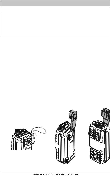
4.2 BELT CLIP, HAND STRAP INSTALLATION AND REMOVAL
To install the Belt Clip: align the Belt Clip to the groove of the Battery pack, then press the Belt Clip downward until it locks in place with a “Click.”
To remove the Belt Clip: press the Belt Clip Tab away from the battery pack to unlock the Belt Clip, then slide the Belt Clip upward to remove it.
To install the Hand Strap: slide the small loop of the Hand Strap through the belt clip as shown below. Next slide big loop on the
Hand Strap inside the small loop and pull tight.
Belt Clip Tab 

Page 10 |
|
HX290 |
|
4.3 BATTERIES AND CHARGERS
If the radio has never been used, or its charge is depleted, it may be charged by connecting the CD-52 Charger Cradle with the PA-44B battery charger, as shown in the illustration. If 12V DC power is available, the optional E-DC-19A
DC Cable with 12 V Cigarette Lighter Plug or the optional E-DC-6 DC Cable may be used for charging the battery. The PA-44B, E-DC-19A, and E-DC-6 will charge a completely discharged FNB-110LI battery pack in about 6 hours.
The FNB-110LI is a high performance Li-Ion battery providing high capacity in a compact package.
CAUTION
To avoid risk of explosion and injury, FNB-110LI battery pack should only be removed, charged or recharged in non-hazardous environments.
4.3.1 BATTERY SAFETY
Battery packs for your transceiver contain Li-Ion batteries. This type of battery stores a charge powerful enough to be dangerous if misused or abused, especially when removed from the transceiver. Please observe the following precautions:
DO NOT SHORT BATTERY PACK TERMINALS: Shorting the terminals that power the transceiver can cause sparks, severe overheating, burns, and battery cell damage. If the short is of sufficient duration, it is possible to melt battery components. Do not place a loose battery pack on or near metal surfaces or objects such as paper clips, keys, tools, etc. When the battery pack is installed on the transceiver, the terminals that transfer current to the transceiver are not exposed. The terminals that are exposed on the battery pack when it is mounted on the transceiver are charging terminals only and do not constitute a hazard.
DO NOT INCINERATE: Do not dispose of any battery in a fire or incinerator. The heat of fire may cause battery cells to explode and/or release dangerous gases.
Battery Maintenance
For safe and proper battery use, please observe the following:
Battery packs should be charged only in non-hazardous environments;
Use only STANDARD HORIZON-approved batteries;
Use only a STANDARD HORIZON approved charger. The use of any other charger may cause permanent damage to the battery.
Follow charging instructions provided with the chargers.
Keep the battery contacts clean.
HX290 |
|
Page 11 |
|

Battery Storage
Store the batteries in a cool place to maximize storage life. Since batteries are subject to self-discharge, avoid high storage temperatures that cause large self-discharge rates. After extended storage, a full recharge is recommended.
Battery Recycling
DO NOT PLACE USED BATTERIES IN YOUR REGULAR TRASH!
LI-ION BATTERIES MUST BE COLLECTED, RECYCLED OR DISPOSED OF IN AN ENVIRONMENTALLY SOUND MANNER.
The incineration, land filling or mixing of Li-Ion batteries with the municipal solid waste stream is PROHIBITED BY LAW in most areas.
Return batteries to an approved Li-Ion battery recycler. This may be where you purchased the battery.
Contact your local waste management officials for other information regarding the environmentally sound collection, recycling and disposal of Li-Ion batteries.
4.3.2 BATTERY INSTALLATION/REMOVAL
To install the battery pack, hold the transceiver with your left hand, so your palm is over the speaker and your
thumb is on the top of the belt clip. Insert the battery pack into the battery
compartment on the back of the radio while tilting the Belt Clip outward, then
push the bottom side of the battery pack until the battery pack locks with the Battery Pack Latch.
To remove the battery, turn the radio off. Slide the Battery Pack Latch on the bottom of the radio, then lift up on the bottom of the battery and remove it from the radio.
Page 12 |
|
HX290 |
|

4.3.3 BATTERY CHARGING
1.Turn the transceiver off.
2.Insert the DC plug from the PA-44B into
the DC jack on the CD-52 Charger Cradle side panel, then plug the PA-44B into the AC line outlet.
3. |
Insert the HX290 (with the battery pack) |
|
|
into the CD-52; the antenna should be at |
|
|
the left side when viewing the charger from |
PA-44B |
|
the front. |
|
|
|
|
4. |
If the HX290 is inserted correctly, the LED |
|
|
indicator will glow red. A fully-discharged |
|
|
pack will be charged completely in ap- |
|
|
proximately 6 hours. |
|
5. |
When charging is completed, the red LED CD-52 |
|
|
indicator will change to green. Remove the |
|
|
transceiver from the CD-52, and unplug |
|
|
the PA-44B from the AC line outlet. |
|
CAUTION
The CD-52 Charger Cradle is NOT designed to be waterproof. Do not attempt to charge in water hazardous locations.
NOTE
The CD-52 Charger Cradle is only designed for the charging of the
HX290’s battery, and is not suitable for other purposes. The CD-52 may contribute noise to TV and radio reception in the immediate vicinity, so we do not recommend its use adjacent to such device.
HX290 |
|
Page 13 |
|
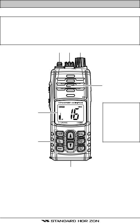
5.CONTROLS AND INDICATORS
5.1CONTROLS AND SWITCHES
NOTE
This section defines each control of the transceiver. For detailed operating instructions, refer to section “6. BASIC OPERATION”. Refer to illustrations for the location of the following controls, switches, and connections.


NOTE
When transmitting, position your mouth about 1/2 to 1 inch (1.2 ~ 2.5 cm) away from the small mic hole.
Speak slowly and clearly into the microphone.
ANT Jack (Top Panel)
The supplied CAT460 flexible antenna is attached here.
MIC/SP Jack (Top Panel)
The jack accepts the optional MH-73A4B Speaker/Microphone, MH-57A4B Mini Speaker/Microphone, VC-24 VOX Headset, or VC-27 Earpiece/Microphone. When this jack is used, the internal speaker and microphone are disabled.
Page 14 |
|
HX290 |
|
 Loading...