


CP155C
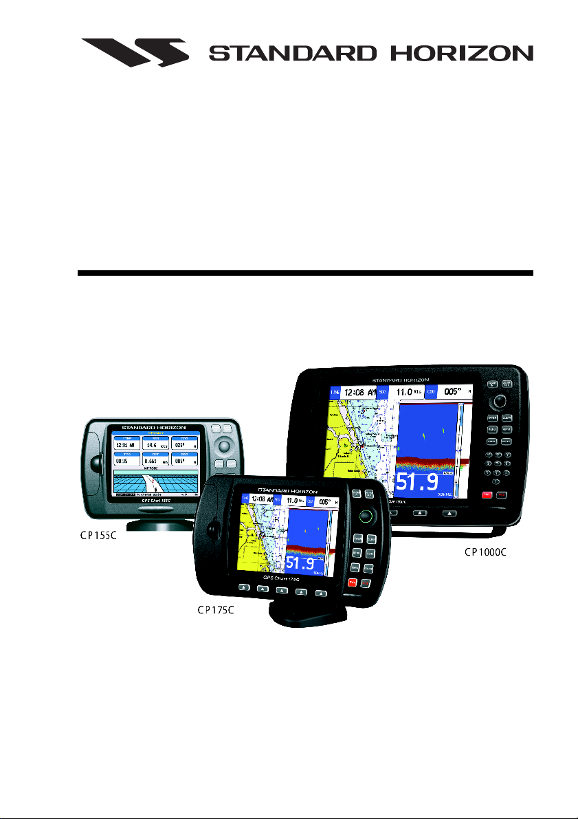
CP155C / CP175C / CP1000C
GPS Chartplotter
Owner's Manual

WARNING!!!
Electronic charts displayed by the chartplotter are believed to be accurate and
reliable, but that are not intended to be a substitute for the official charts, which
should remain your main reference for all matters related to the execution of safe
navigation.
For this reason we would like to remind you that you should carry on board and use
the official published and approved nautical charts.
FCC Compliance Statement
This device complies with Part 15 of the FCC limits for Class A digital devices. This
equipment generates, uses, and can radiate radio frequency energy and, if not
installed or used in accordance with the instructions may cause harmful interference
with radio communications.
There is no guarantee that interference will not occur in a particular instance. If this
equipment does cause harmful interference to other equipment, try to correct the
problem by relocating the equipment.
Consult an authorized STANDARD HORIZION dealer or other qualified service
technician if the problem cannot be corrected. Operation is subject to the following
conditions: (1) This device cannot cause harmful interference, and (2) this device
must accept any interference received, including interference that may cause
undesired operation.
Copyright 2004. STANDARD HORIZON All rights reserved. Printed in Italy.
No part of this publication may be reproduced or distributed in any form or by any means, or stored in a database
or retrieval system, without prior written permission of the publisher.

Congratulations on you purchase of the GPS chartplotter!
Whether this is your first chartplotter, or if you have other STANDARD
HORIZON equipment, the STANDARD HORIZON organization is committed
to ensuring your enjoyment of this chartplotter. STANDARD HORIZON
technical support personnel stand behind every product we sell, and our
Product Support team invites you to contact us should you require technical
advice or assistance, at 800/767-2450.
CLEANING PROCEDURE FOR THE CHART PLOTTER SCREEN
Cleaning of the chartplotter screen is a very important operation and must be done
carefully. Since the surface is covered by a antireflective coating, the procedure for
cleaning all the surfaces can be performed using the following procedure: You need
a tissue or lens tissue and a cleaning spray containing Isopropanol (a normal spray
cleaner sold for the PC screen, for example PolaClear by Polaroid). Fold the tissue
or lens tissue into a triangular shape, moisten the tip and use the index finger behind
a corner to move the tissue across the surface, in overlapping side to side strokes.
If the tissue is too wet, a noticeable wet film will be left in its path and you will need
to repeat the process. If too dry, the tissue won’t glide easily, and may damage the
surface.

Page 6 GPS chartplotters
CAUTION
- The chartplotter is designed for maritime use. Please give attention to avoid water
intrusion into the C-MAP NT
+
C-CARD cartridge holder.
- Extensive exposure to heat may result in damage to the chartplotter.
- The chartplotter contains dangerous high voltage circuits which only experienced
technicians can handle.
- STANDARD HORIZON will not be liable for errors contained herein, or for
incidental or consequential damages in connection with the performance or use
of this material.

GPS chartplotters Page 7
TABLE OF CONTENTS
1. INTRODUCTION ...................................................................................................... 11
1.0 GENERAL INFORMATION .................................................................................... 11
1.1 PACKING LIST ...................................................................................................... 11
1.1.0 CP155C Packing List ................................................................................. 11
1.1.1 CP175C Packing List ................................................................................. 12
1.1.2 CP1000C Packing List ............................................................................... 12
1.2 OPTIONAL ACCESSORIES .................................................................................. 12
1.2.0a CP155C Optional Accessories .................................................................. 12
1.2.0b CP1000C Optional Accessories ................................................................ 12
2. GETTING STARTED ...................................................................................................... 15
2.0 MOUNTING THE GPS CHARTPLOTTER ............................................................. 15
2.1 BRACKET MOUNTING .......................................................................................... 15
2.2 FLUSH MOUNTING ................................................................................................ 15
2.3 MOUNTING THE GPS SMART ANTENNA ........................................................... 16
2.3.0 Flush Mounting .......................................................................................... 17
2.4 CONNECTIONS ..................................................................................................... 17
2.4.0a Connection Table for CP155C/CP1000C .................................................. 18
2.4.0b Connection Table for CP175C ................................................................... 18
2.4.1a Connection for CP155C ............................................................................. 19
2.4.1b Connection for CP175C ............................................................................. 19
2.4.1c Connection for CP1000C ........................................................................... 19
2.5 BATTERY CONNECTIONS ................................................................................... 20
2.6 NMEA CONNECTIONS .......................................................................................... 20
2.7 GPS POSITION ON A VHF RADIO ....................................................................... 20
2.8 OPTIONAL BLACK BOX FISH FINDER ................................................................ 21
2.9 CONNECTING DIGITAL INSTRUMENTS/AUTOPILOT/RADAR .......................... 21
2.10 OUTPUTTING NMEA TO A PERSONAL COMPUTER......................................... 21
2.11 NMEA DATA PAGE ................................................................................................ 22
2.12 VIDEO INPUT (for CP1000C only) ......................................................................... 22
2.12.0 Video Camera Input .................................................................................... 22
2.12.1 VCR or DVD Input ....................................................................................... 22
2.13 OPTIONAL C-MAP NT+ CARTOGRAPHY ............................................................ 24
2.14 INSERTING THE C-CARD ..................................................................................... 24
3. CONTROLS AND INDICATORS ...................................................................................... 25
3.0 CONTROLS AND CONNECTIONS ....................................................................... 25
3.0a The alphanumeric keys on CP1000C .................................................................... 26
3.0b The soft keys on CP175C/CP1000C ...................................................................... 26
3.1 GETTING STARTED .............................................................................................. 26
3.1.0 Power On, Off and ShuttlePoint operation ................................................ 26
3.1.1 Cursor Vs. Home Mode ............................................................................. 27
3.1.2 Cursor and Menu selection speed ............................................................. 28
3.1.3 Changing the Ships Icon ........................................................................... 28
3.1.4 Changing the backlight and contrast ......................................................... 29
3.1.5 Selecting North Up or Course Up .............................................................. 29
3.2 ADJUSTING THE TIME ......................................................................................... 30
3.3 SELECTING LORAN TD OR OTHER COORDINATE SYSTEM .......................... 31
3.4 CHANGING THE CHART COLOR ......................................................................... 32
3.5 SELECTING PAGES USING SOFT KEYS ............................................................ 32
3.6 CUSTOMIZING THE SOFT KEYS .........................................................................33

Page 8 GPS chartplotters
3.7 OTHER SETTINGS IN GENERAL SETUP MENU ................................................ 33
4. USING FIND SERVICES & MORE FUNCTION .............................................................. 35
4.0 PORT SERVICES................................................................................................... 35
4.1 OTHER AVAILABLE SEARCHES .......................................................................... 35
5. CREATING MARKS ...................................................................................................... 37
5.0 CREATING A NEW MARK USING THE CHART PAGE ....................................... 37
5.1 EDITING a MARK ................................................................................................... 37
5.1.0 Deleting a Mark or Waypoint ......................................................................... 38
5.1.1 Moving a Mark or Waypoint ........................................................................... 38
5.2 MARK/WAYPOINTS LIST ...................................................................................... 39
5.3 Creating a NEW MARK with the MARK/WAYPOINTS LIST ................................. 39
5.4 GOTO CURSOR ..................................................................................................... 40
5.5 GOTO MARK ...................................................................................................... 41
6. Man Over Board (MOB) Function .................................................................................. 43
6.0 DELETING A MOB POINT ..................................................................................... 43
7. ROUTES ...................................................................................................... 45
7.0 CREATING A ROUTE USING WAYPOINTS ........................................................ 45
7.1 MAKING ADDITIONAL ROUTES ........................................................................... 46
7.2 CREATING A ROUTE USING MARKS ON THE CHART PAGE ..........................46
7.3 INSERTING A WAYPOINT INTO A ROUTE ......................................................... 47
7.4 GOTO A ROUTE .................................................................................................... 47
7.4.0 By select Route .......................................................................................... 47
7.4.1 By Cursor key ............................................................................................ 47
7.5 OTHER SETTINGS IN ROUTE MENU .................................................................. 47
8. TRACKS ...................................................................................................... 49
8.0 TRACKING ...................................................................................................... 49
8.0.0 Saving and starting a new Track ............................................................... 50
8.0.1 Other Settings in Track Menu .................................................................... 50
8.1 USING THE TRIP LOG .......................................................................................... 50
8.1.0 Resetting the Trip Log ............................................................................... 51
9. USER C-CARD ...................................................................................................... 53
9.0 USER C-CARD MENU ........................................................................................... 53
9.0.0 Formatting the User C-CARD .................................................................... 53
9.0.1 Transferring files to the optional User C-CARD ........................................ 54
9.0.2 Loading a file .............................................................................................. 54
9.0.3 Deleting a file from the User C-CARD ....................................................... 54
9.0.4 Changing the User C-CARD ...................................................................... 54
10. PAGES ...................................................................................................... 55
10.0 CHART PAGE ...................................................................................................... 56
10.0.0 Window Selections ......................................................................................56
10.0.1 Additional Functions on Chart Page .......................................................... 57
10.0.2 Turning Off Information on Icon Points ..................................................... 57
10.0.3 Setting up the Chart Page using the Map Setup Selection ...................... 57
10.0.4 Advanced Chart SetUp .............................................................................. 58
10.0.5 Customizing the Data Windows ................................................................ 59
10.1 CUSTOMIZING CHART SETTINGS ...................................................................... 60
10.2 NAVIGATION PAGE .............................................................................................. 60
10.3 HIGHWAY PAGE ................................................................................................... 61
10.4 CELESTIAL PAGE ................................................................................................. 62
10.5 GPS STATUS PAGE .............................................................................................. 62
10.6 NMEA DISPLAY PAGE .......................................................................................... 63
10.7 NMEA DATA PAGE ................................................................................................ 63
10.8 NMEA DEPTH, WIND SPEED, TEMP AND SOG TREND PAGES...................... 64

GPS chartplotters Page 9
10.9 VHF DIGITAL SELECTIVE CALLING .................................................................... 64
10.9.0 Interfacing .................................................................................................. 64
10.9.1 DSC Distress Call ...................................................................................... 65
10.9.2 Position Request ........................................................................................ 65
11. ADVANCED SETTINGS ................................................................................................... 67
11.0 INPUT/OUTPUT (NMEA) ....................................................................................... 67
11.1 NAVIGATE ...................................................................................................... 67
11.2 COMPASS ...................................................................................................... 68
11.3 ALARMS ...................................................................................................... 69
12. TROUBLE SHOOTING ..................................................................................................... 71
13. TECHNICAL TESTS ...................................................................................................... 73
13.0 SYSTEM TEST ...................................................................................................... 73
13.0.0 RAM Menu (reset) ...................................................................................... 73
13.0.1 DIM Menu ................................................................................................... 73
13.0.2 Cartridges ................................................................................................... 74
13.0.3 Serial Ports ................................................................................................ 74
13.0.4 Modem test ................................................................................................ 74
14. SPECIFICATIONS ...................................................................................................... 75
14.0a CP155C SPECIFICATIONS ................................................................................... 75
14.0b CP175C SPECIFICATIONS ................................................................................... 76
14.0c CP1000C SPECIFICATIONS ................................................................................. 77
14.1 Smart WAAS Receiver Specifications ................................................................... 78
15. APPENDIX: TERMS ...................................................................................................... 79
INDEX ...................................................................................................... 81

Page 10 GPS chartplotters

GPS chartplotters Page 11
1. INTRODUCTION
1.0 GENERAL INFORMATION
The GPS chartplotter is a precision-crafted, high-performance receiver for the Global
Positioning System (WAAS GPS) constellation of satellites, providing precise location data
with a host of navigation features. Idea for nautical use and sealed against water ingress.
The GPS chartplotter is housed in a rugged, impact-resistant case with outstanding
ergonomic design, for effortless operation.
The advanced features of the GPS chartplotter include:
· Direct sunlight viewable color LCD display
· Capable of using the Optional FF520 50/200kHz black box 500W or 1KW Fish Finder
· C-MAP NT or NT
+
cartography compatible
· Improved New Worldwide background showing C-MAP NT
+
detail up to 2.0 NM
· 12 Channel WAAS GPS Smart antenna, bracket and flush mounting hardware
· for CP155C : 600 Waypoints (Marks) / 20 Routes storage
for CP175C: 1000 Waypoints (Marks) / 20 Routes storage
for CP1000 : 3000 Waypoints (Marks) / 50 Routes storage
· User selectable data fields
· NMEA Data pages
· 3 NMEA Output and 3 Inputs
· Connections to and from STANDARD HORIZON DSC VHF’s for Distress and Position
Request calls
· 3 year limited warranty, lifetime flat rate
1.1 PACKING LIST
When the package containing the chartplotter is first opened, please check for the
following contents.
If any parts are missing contact the dealer this chartplotter was purchased from.
Accessories and replacement parts may be ordered from STANDARD HORIZON’s Parts
Department at 562/404-270 Ext. 351 or via the web at www.standardhorizon.com.
1.1.0 CP155C Packing List
REPLACEMENT PART ITEM
TT150001CP External bracket (includes the knob)
RR150002CP Dust cover
TT90000001 Power data cable
UU90000001 Flush mounting screws
RR15000001 Flush mount template
XUS0003911 Smart DGPS WAAS Antenna
XUCMP0066 Owner’s Manual
XUCMP0067 Quick Reference Guide
Page 12 GPS chartplotters
1.1.1 CP175C Packing List
REPLACEMENT PART ITEM
RR16000001 Quick Disconnect Bracket
RR16000002 Protective Cover
UU90000001 Flush mounting screws
RR1600003 Flush mount template
Q0000003 2 amp fuse and holder
XUS0003911 Smart DGPS WAAS Antenna
XUCMP0066 Owner’s Manual
XUCMP0067 Quick Reference Guide
1.1.2 CP1000C Packing List
REPLACEMENT PART ITEM
XUS0003907 Bracket
XUS0003908 Protective Cover
XUS0003909 Flush mounting screws
XUS0003910 Flush mount template
XUS0003913 2 amp fuse and holder
XUS0003911 Smart DGPS WAAS Antenna
XUCMP0066 Owner’s Manual
XUCMP0067 Quick Reference Guide
1.2 OPTIONAL ACCESSORIES
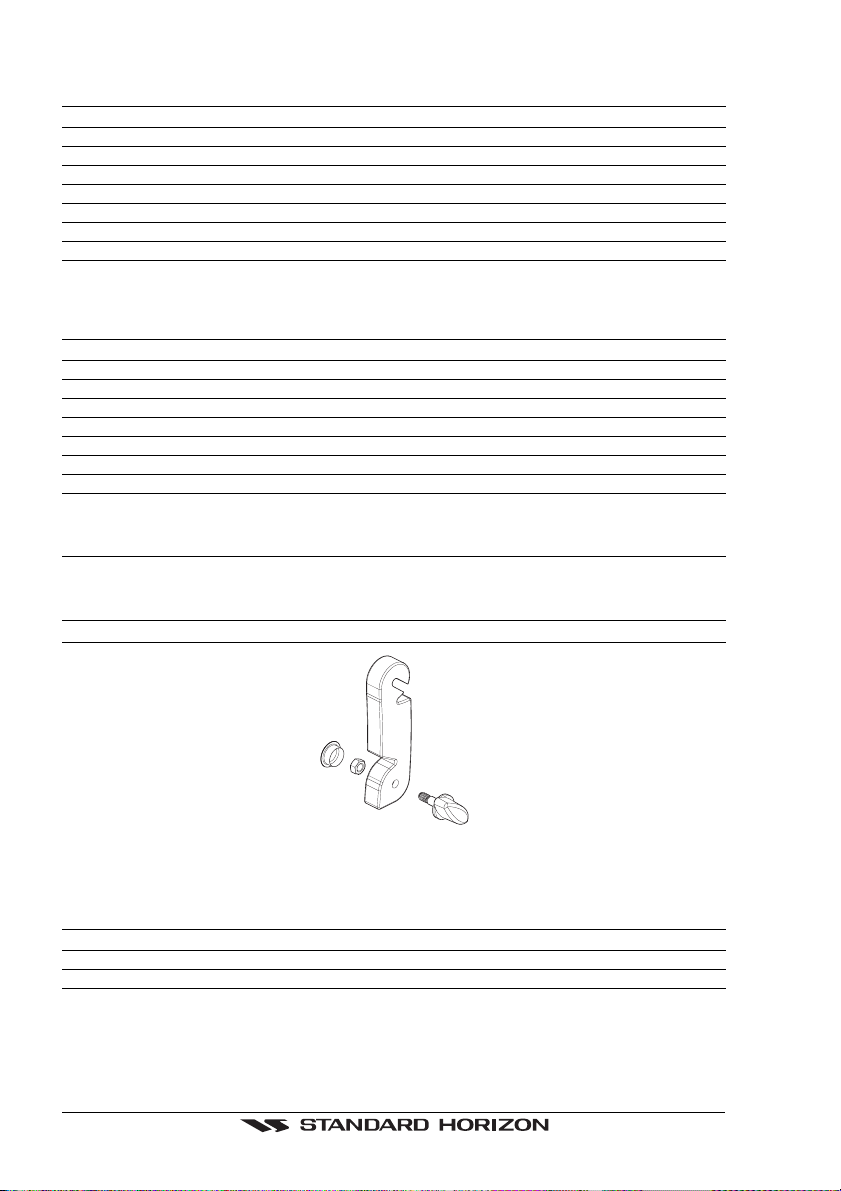
1.2.0a CP155C Optional Accessories
PART NUMBER ITEM
RR150003CP Overhead mounting bracket
Figure 1.2.0a - CP155C Bracket
1.2.0b CP1000C Optional Accessories
PART NUMBER ITEM
VC10 Color Video Camera with 40 feet of cable
ECVC10 34 feet Extension Cable
ACVC10 DVD or VCR adapter cable
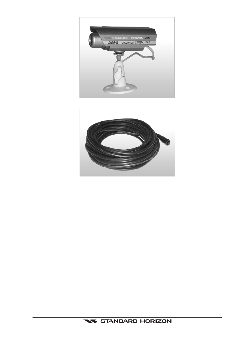
GPS chartplotters Page 13
Figure 1.2.0b - Color Video Camera
Figure 1.2.0ba - Extension Cable

Page 14 GPS chartplotters
GPS chartplotters Page 15
2. GETTING STARTED
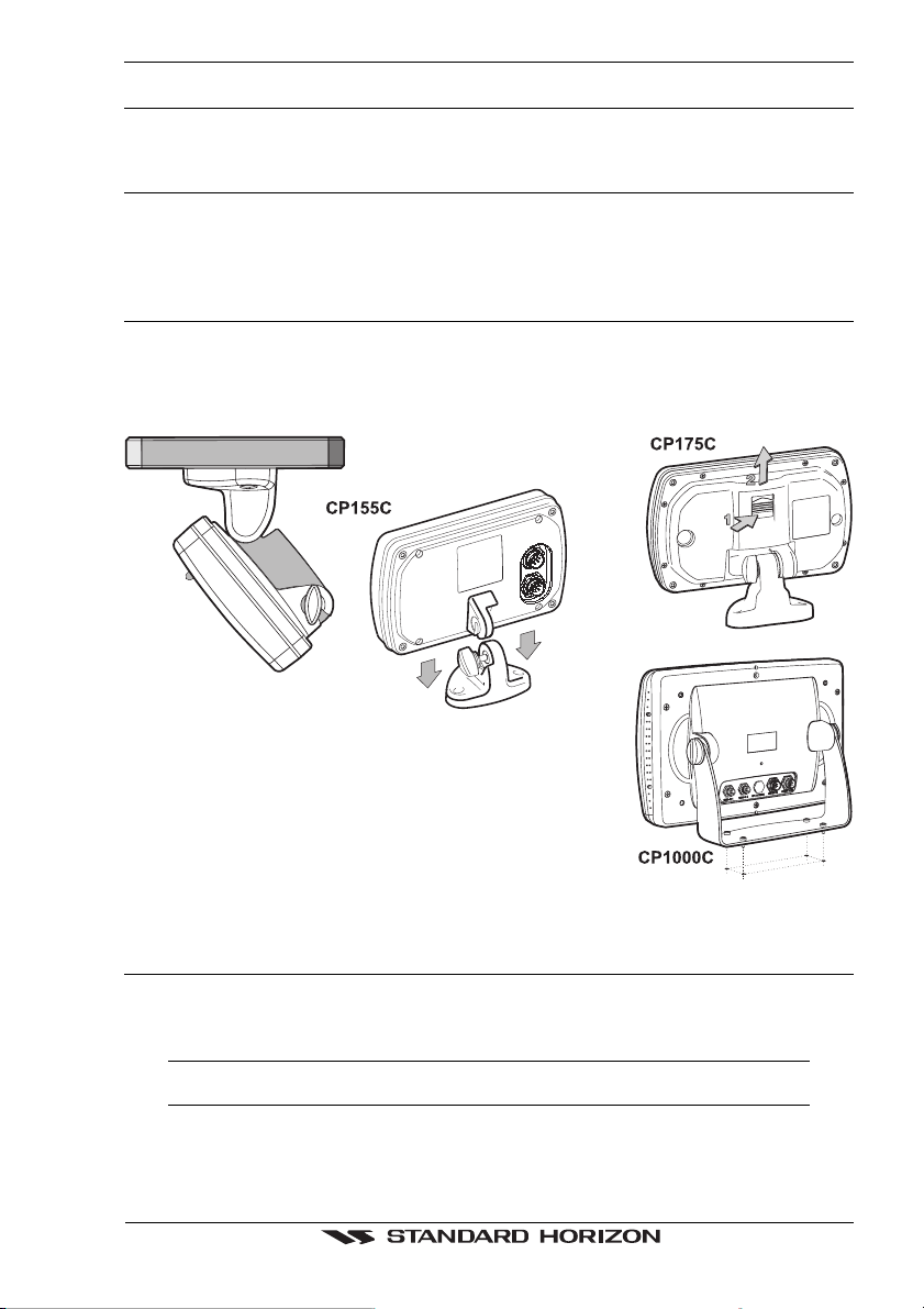
2.0 MOUNTING THE GPS CHARTPLOTTER
The GPS chartplotter is supplied with hardware for bracket or flush mounting. Below are
pictures showing actual examples of the two types of installation.
2.1 BRACKET MOUNTING
The GPS chartplotter can be mounted using the supplied bracket. Before installing ensure
the area the plotters bracket is mounted to is strong enough to support the weight of the
chartplotter especially while under way.
After the location is found, attach the mounting base to the area using the supplied hardware.
Figure 2.1 - Installing/removing chartplotter (Bracket)
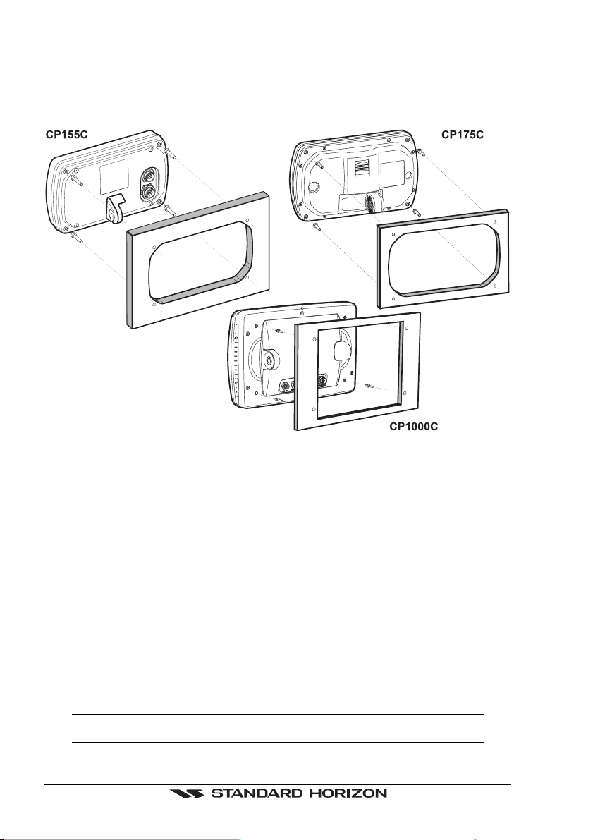
2.2 FLUSH MOUNTING
The GPS chartplotter is supplied with a flush mount template for the cutout hole and screw
holes required to install the chartplotter.
NOTE
Before drilling holes ensure there are no obstructions behind the location that could interfere with
the mounting and there is physically enough room to mount the chartplotter.
1. After a location is found, peal the template label from the backing and apply the label
to the mounting area.
Page 16 GPS chartplotters
2. Drill a hole in one area of the cut area that will allow the blade of a jig saw to be inserted.
Insert and cut out the area on the panel using the jig saw.
3. Next drill the four holes required to insert the chartplotter with the mounting studs.
4. Install the mounting studs on the chartplotter and insert into the mounting hole.
5. Attach the chartplotter to the mounting location by attaching the supplied hardware to
the mounting studs.
Figure 2.2 - Installing/removing chartplotter (Flush)
2.3 MOUNTING THE GPS SMART ANTENNA
The GPS chartplotter is supplied with a 12 Channel WAAS GPS Smart antenna. This
antenna is designed to be mounted on a base, installed on an extension or even flush
mounted.
Choose a location for the antenna that has a clear view of the sky and is not located within
3 FT of RADAR or other transmitting antenna. Ensure there are no major obstructions or
fixtures in the immediate proximity to the antenna. The antenna relies on direct “line of sight”
satellite reception. If you are unsure of the chosen location, temporarily mount the antenna
in the desired location to verify correct operation. If mounted close to RADAR, and after the
GPS chartplotter has a fix, turn on the RADAR to ensure the GPS chartplotter holds the fix
(use the GPS Status Page).
The thread used on the antenna is an industry standard (1inch 14TPI) used on a wide range
of mounting brackets. Due to the manufacturing process of these mounting brackets you
may see some slop when tightening down the antenna to the bracket. This is no concern
however as the antenna must be tightened until the antenna stops rotating.
NOTE
The antenna cable can be cut and spliced to ease installation. Care must be taken when
reconnecting the antenna cable to protect from water and corrosion.

GPS chartplotters Page 17
2.3.0 Flush Mounting
NOTE
Before drilling holes, it is recommended the GPS antenna be positioned where the location is
planned to be drilled, cable connected to the Plotter and the GPS chartplotter turned on to ensure
a GPS FIX is received.
1. Remove the threaded base from the GPS antenna dome.
2. To ease installation a flush mounting template for the antenna has been included.
3. Apply the mounting template sticker to the area that was verified for GPS reception.
4. Then, drill out the 0.63” (16mm) and 0.16” (4mm) holes, and remove the template.
5. Insert the cable into the 0.63” (16mm) hole and route to the GPS chartplotter.
6. Apply a small amount or RTV to the under side of the antenna.
7. Place the antenna and then screw it into place using the screws. In some cases the
screw may not be long enough, if this happens simply apply more RTV to the underside
of the antenna to glue it into place.
Figure 2.3.0 - Installing the GPS Smart antenna
Figure 2.3.0 - Installing the GPS Smart antenna (Flush)
2.4 CONNECTIONS
The GPS chartplotter has a cable or connectors that are used to connect the chartplotter
to Power Supply, to the GPS smart antenna, optional FF520 Black Box Fish Finder and to
NMEA devices such as VHF’s, digital instruments and autopilots.
NOTE
The GPS chartplotter can send many sentences to external NMEA devices. The NMEA output
wires are Brown and White. If you have connected devices as shown in the below table and need
to feed NMEA to other devices (Autopilot RADAR…) you can parallel wires from the Brown or White
wires.

Page 18 GPS chartplotters
2.4.0a Connection Table for CP155C/CP1000C
12VDC Power and NMEA Cable
Pin Wire Color Description Connection Example
1 Black Battery Ground Connect to battery ground and Black wire of GPS Antenna
2 Red Battery Positive Connect to Battery Positive and Red wire of GPS Antenna
3 Green NMEA Common Common for NMEA devices
4 Blue VHF Input Conncect to VHF with DSC and DSE output
5 Brown VHF output Connect to VHF to supply GPS position data
6 Gray Fishfinder Input Standard Horizon Fishfinder, see FF520 owner's manual
7 White Fish Finder Output Standard Horizon Fishfinder, see FF520 owner's manual
8 Yellow GPS Antenna Input Connect to GPS Antenna Green wire
Smart GPS Cable
Pin Wire Color Description Connection Example
1 Red Battery Positive Connect to Battery Positive and Red wire of GPS
Antenna
2 Green Smart GPS NMEA Input Connect to Smart GPS Input
3 Brown Smart GPS NMEA Output Connect to Smart GPS Output
4NC
5NC
6 Black/Yellow Battery Ground Connect to battery ground and Black wire of GPS
Antenna
NOTE
The CP155C and CP1000C have connectors on the rear panel that allow the GPS Smart antenna
to be directly connected.
Video Connector for CP1000C
Pin Description Connection Example
1 Ground Connect to Video Signal Ground of DVD/VCR/Video Cameras
2 + 9 / 12 VDC Connect to Video Cameras Power Input
3 Video Signal + Connect to Video Signal + of DVD/VCR/Video Cameras
2.4.0b Connection Table for CP175C
12VDC Power and NMEA Cable
Wire Color Description Connection Example
Black Battery Ground Connect to battery ground and Black wire of GPS Antenna
Red Battery Positive Connect to Battery Positive and Red wire of GPS Antenna
Green NMEA Common Common for NMEA devices
Blue VHF Input Conncect to VHF with DSC and DSE output
Brown VHF output Connect to VHF to supply GPS position data
Gray Fish Finder Input Standard Horizon Fish Finder, see FF520 owner's manual
White Fish Finder Output Standard Horizon Fish Finder, see FF520 owner's manual
Yellow GPS Antenna Input Connect to GPS Antenna Green wire
Pink GPS Antenna Output Connect to GPS Antenna Brown wire
Orange Not used No connection
NOTE
For the CP175C the GPS Smart antenna should be wired according to the below diagram.
GPS chartplotters Page 19
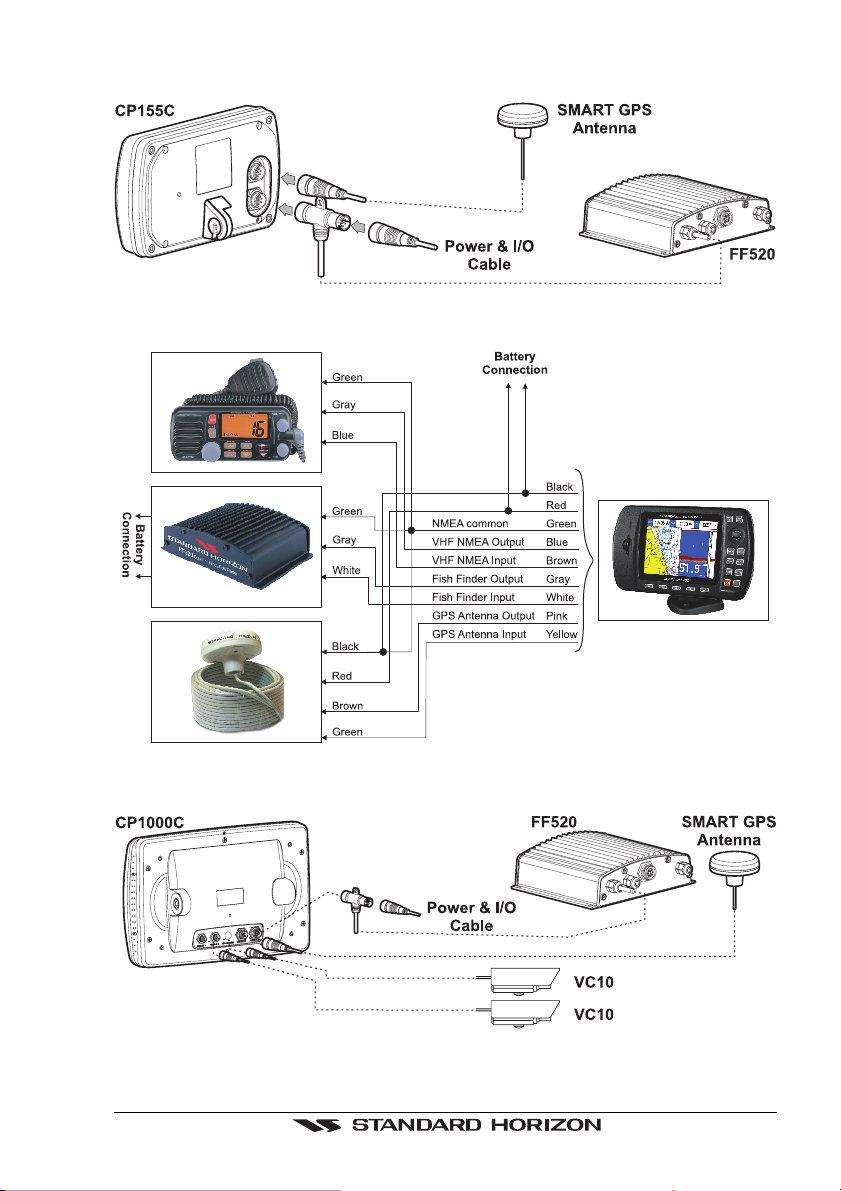
2.4.1a Connection for CP155C
2.4.1b Connection for CP175C
2.4.1c Connection for CP1000C
Page 20 GPS chartplotters
2.5 BATTERY CONNECTIONS
1. The GPS chartplotter is supplied with a fuse and holder. This fuse should be installed
into the Black wire to protect the NMEA output/input circuits from becoming damaged.
2. Connect the Red and Black wires from the GPS chartplotter and the GPS antenna
together and route to a 12VDC source as direct as possible,
2.6 NMEA CONNECTIONS
The GPS chartplotter can be connected external devices with NMEA and display informa-
tion, examples:
- DSC VHF Radio
- Optional FF520 Dual frequency Black Box Fish Finder
- Depth Sounder, Speed Log, Wind Instrument, AutoPilot etc.
- Radar
- Personal Computer
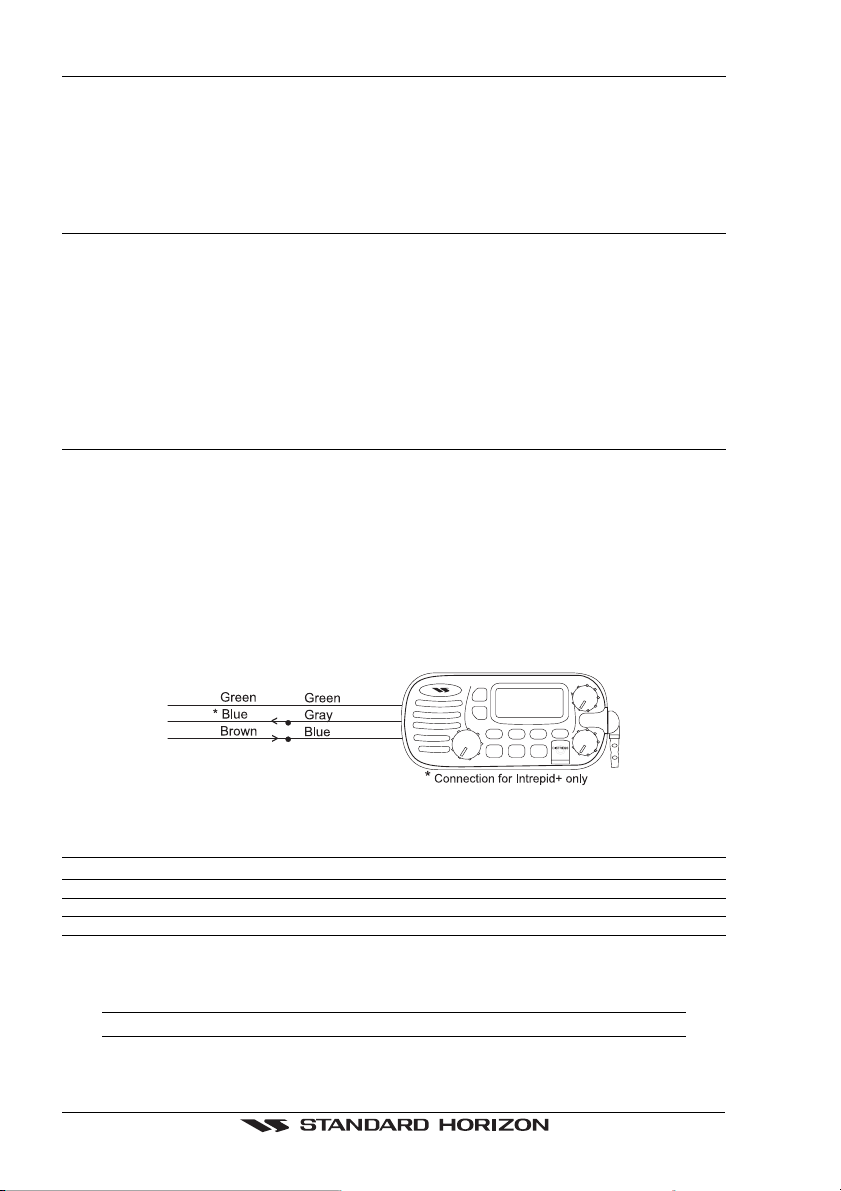
2.7 GPS POSITION ON A VHF RADIO
STANDARD HORIZON has pioneered Digital Selective Calling (DSC) on VHF radios.
Advancements in DSC have made it possible to show the coordinates of a vessel that has
transmitted a DSC Distress Call or even Poll the location of another vessel and show the
position of that vessel on the display of STANDARD HORIZON VHFs.
STANDARD HORIZON has taken this feature one step further, if the Standard Horizon GPS
chartplotter is connected a STANDARD HORIZON DSC capable VHF, the vessel in
Distress or the polled position of the vessel is shown on the display of the GPS chartplotter,
making it easy to navigate to the location of the vessel. This is a great feature that could save
someone’s life or for anyone wanting to know the position of another vessel.
Figure 2.7 - GPS Position on a VHF Radio Connections
Other DSC VHF Manufactures
GPS Chartplotter Description VHF
Green NMEA Common Ground Connect to NMEA Ground
Brown NMEA Positive Output Connect to NMEA Input
Blue NMEA Positive Input * Connect to NMEA Output (if available)
* Some manufactures of DSC VHF’s are not capable to receiving DSC information from the GPS
chartplotter.
Refer to the owner’s manual of the VHF.
NOTE
Refer to VHF Digital Selective Calling section for operation.
GPS chartplotters Page 21
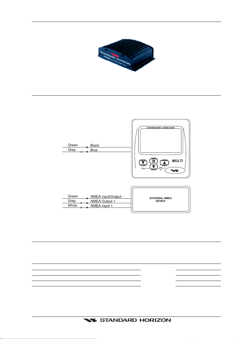
2.8 OPTIONAL BLACK BOX FISH FINDER
STANDARD HORIZON offers an optional black box fish finder called FF520. Pls refer to the
manual supplied with the Fish Finder for connections and operation.
Figure 2.8 - Fish Finder FF520
2.9 CONNECTING DIGITAL INSTRUMENTS/AUTOPILOT/RADAR
The GPS chartplotter can be connected to any of the following instrument if they have NMEA
output: Depth Sounder, Speed Log with temperature, Wind Speed and Direction, Flux Gate
Compass, Auto Pilot and Radar.
Figure 2.9 - Connecting Digital Instruments/Autopilot/Radar
2.10 OUTPUTTING NMEA TO A PERSONAL COMPUTER
The GPS chartplotter can be connected to output Marks, Routes and tracks to many PC
programs available in the aftermarket. To send or receive User points the PC Program must
be able to receive NMEA WPL and RTE sentences.
Pin PC DB9 connection NMEA connection NMEA connection
2 Receive Brown White
3 Transmit Blue Gray
5 Signal ground Green Green
or
Page 22 GPS chartplotters
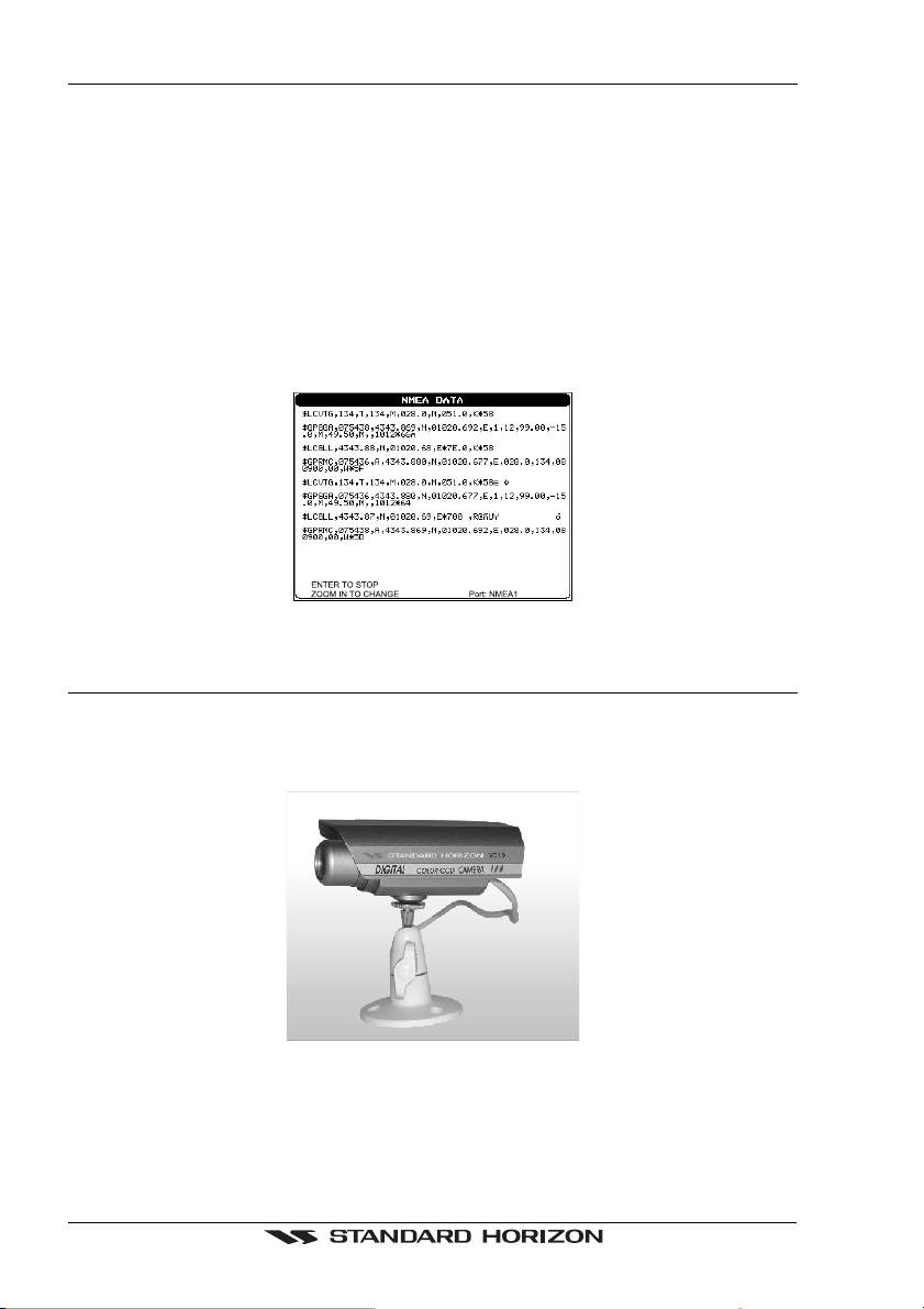
2.11 NMEA DATA PAGE
The NMEA Data Page is very useful to see if a External device (example: Depth Sounder)
is transmitting NMEA sentences to the GPS chartplotter. This page can also be used to see
if the GPS chartplotter NMEA output is being loaded down by a external NMEA device the
GPS chartplotter is connected to.
Scenario:
VHF Radio connected but the radio is not receiving a GPS Position.
Usually the VHF radio will be connected to the Green and Brown wires. To check
to see if the GPS chartplotter is transmitting the sentences:
1. Press [MENU] and highlight
NMEA DISPLAY with the ShuttlePoint knob.
2. Press [ENTER] or move the ShuttlePoint knob to the right and highlight
DATA
3. Press [ENTER] or move the ShuttlePoint knob to show the
NMEA DATA page.
4. Connect the BLUE Wire on the GPS chartplotter to the junction of the Brown wire and
the VHF wire. The display should look similar to the picture below.
Figure 2.11 - NMEA Data page
2.12 VIDEO INPUT (for CP1000C ONLY)
2.12.0 Video Camera Input
STANDARD HORIZON offers a above deck waterproof color camera called VC10. Up to
2 cameras can be attached to the CP1000C with the rear panel connectors.
Figure 2.12.0 - Color Video Camera
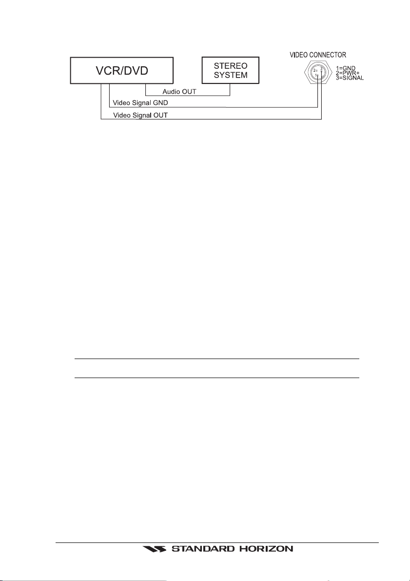
2.12.1 VCR or DVD Input
A VCR or DVD may be connected to either Video1 or Video2 port. The CP1000C does not
have speakers so the audio from the VCR or DVD would have to be routed to a stereo system.
GPS chartplotters Page 23
Standard Horizon offers an optional cable called ACVC10 that allows any VCR or DVD
to simply be plugged into the CP1000C.
Figure 2.12.1 - VCR/DVD Input
The CP1000C has the capablity to select the Video Input in three ways.
1. From the menu
Press [MENU], select
SETUP, press [ENTER], select VIDEO INPUT press [ENTER],. A
menu appears with the following options:
a.
ACTIVATE VIDEO, the possible choices are Input 1, Input 2, Auto Switch (*).
Activates the video mode to show the selected Video Input. If Input 1 or Input 2 is
chosen, the chart plotter will show a warning message with the instructions to adjust
the image from the selected Video Input. If the user agrees to proceed, the image from
the selected video input will be shown. If Auto Switch is chosen, all the menus will
be closed and the video input will be shown switching between the other Video Input
(if connected) and the CHART page. See next section for details of setting up the
switching times. If the user agrees to proceed, the image from the selected video
input/s and the chart plotter page will be shown intermittently. The intermittence time
is selected by Switching Timeout item.
b.
SWITCHING TIMEOUT, the possible choices are 5,10,30 sec, 1, 5, 10 min. Allows
selecting the timing to change from Video inputs and chart plotter display.
c.
RESTORE DEFAULTS, the possible choices are Input 1, Input 2, All (*). Allows
restoring the factory defaults for the Input 1 and Input 2 picture adjustment. The user
can decide to reset the default for Input 1 or Input 2 individually, or to restore the
defaults of the two Video Input simultaneously. When Restore default is executed, the
message “OK” is shown next to the selected menu item.
NOTE (*)
If the video signal is not present on the video connector, the corresponding item in the menu will
be shown with a light color (to identify that the option is not available).
2. Quick Activation by pressing [CLEAR] for 1 second
Pressing and holding [CLEAR] for 1 second from the Map Display or from any main page
(Chart, Navigation, Highway, Celestial, GPS Status, DSC, NMEA DISPLAY); the following
soft keys are shown: “I
NPUT 2”, “INPUT 1”, “AUTO SWITCH”. If no video signal is detected on
the Video Input connectors, the 3 soft keys will be shown in light color in order to identify
that they are not active.If only one video signal is detected on the Video Input connectors,
the corresponding soft key and “A
UTO SWITCH” will be shown with dark color and the other
soft keys will be shown with light color.
3. Quick Activation by soft keys
It will be possible to assign the possibility to set the Video Input mode to any of the 5 soft
keys. Press one of the soft keys, the soft keys functions are shown. Pressing and holding
for 1 second one of the soft keys, the soft key customization list will be shown. By selecting
VIDEO option it will be possible to assign the soft key to execute the Video Input function.
Once the soft key has been associate to Video Input, its label will show the message
Page 24 GPS chartplotters
“VIDEO”. If “VIDEO” is pressed, the soft keys will be assigned this way: “INPUT 2”, “INPUT 1”,
“A
UTO SWITCH”. From now on, the functioning is identical to case 2.
2.13 OPTIONAL C-MAP NT
+
CARTOGRAPHY
STANDARD HORIZON has taken advantage of C-MAP’s experience with professional
navigation, by allowing the use of the refined and improved cartography called NT
+
. The new
cartography of NT
+
makes creative use of colors, patterns and icons to increase the
familiarity and usability of the much larger coverage database of NT
+
. NT
+
is supplied by
C-MAP in four sizes Local, Standard, Wide and SuperWide. For convenience the older NT
and the NT
+
are both compatible with all STANDARD HORIZON chartplotters. Contact
C-MAP USA at (508) 477-8010 or visit
www.c-map.com for further information on NT
+
.
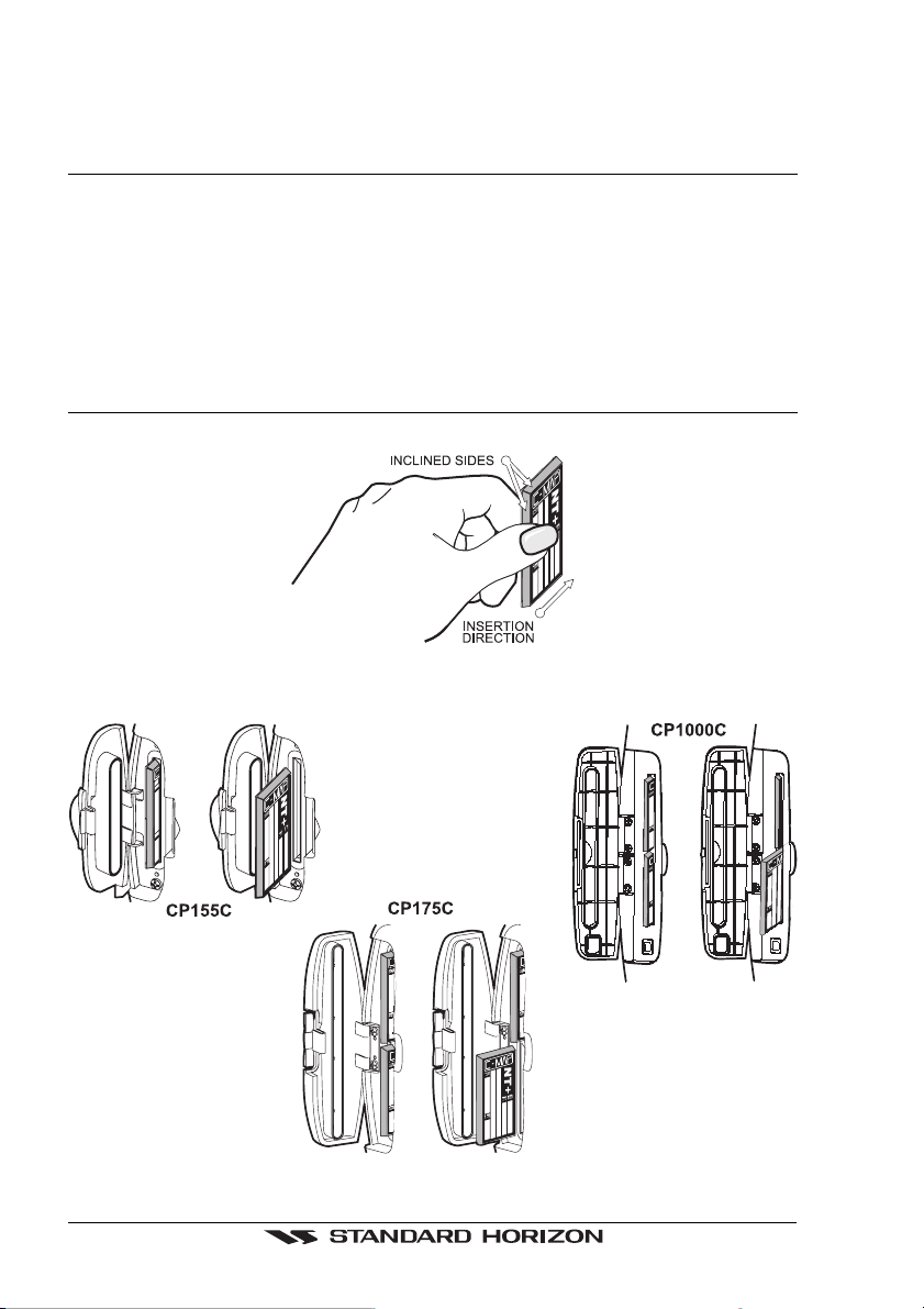
2.14 INSERTING THE C-CARD
Hold the C-CARD by the long inclined side so that you can see the C-MAP label.
Figure 2.14 - Inserting C-CARD
Open the door, gently push the C-CARD into one of the two slots (one slot for CP155C): push
the C-CARD in as far as it will go, then close the door.
Figure 2.14a - Inserting C-CARD (Details)

GPS chartplotters Page 25
3. CONTROLS AND INDICATORS
NOTE
This section defines each control of the chartplotter. For instructions, refer to Getting Started and
Advanced Settings sections of this Owner's Manual.
3.0 CONTROLS AND CONNECTIONS
The chartplotter is controlled by using the keys located on the front panel. These labeled keys
are dedicated to specific functions. As you press a key, a single audio beep confirms the key
action; every time a key press is not valid, three rapid beeps sound to indicate that the key
action is not valid. There is also a ShuttlePoint knob to move the cursor across the screen.
The ZOOM IN and ZOOM OUT keys
Pressing [ZOOM IN] shows more detail of a smaller area, by changing the chart scale and
zooming in on your display. Press [ZOOM OUT] to change the scale and show a wider,
otherwise less detailed view. Pressing and holding [ZOOM IN]/[ZOOM OUT] allows the
quick zoom, that is the fast change of the chart scale where only the land areas are drawn.
When [ZOOM IN]/[ZOOM OUT] is released all map details are shown.
NOTE
The GPS chartplotter contains a background map of North America that allows you to zoom into
2NM. For more detail, a C-MAP NT or NT
+
card must be purchased and installed.
The ShuttlePoint knob
The ShuttlePoint knob moves the cursor about on the display screen, quickly and
accurately. It also scrolls the desired option in the menu page(s). It allows to exit from Home
mode to Cursor mode. When into menu pages moving it to right selects the desired option,
as [ENTER], moving it to the left exits from menu, as [CLEAR]. For a detailed explanation
of Cursor VS home mode refer to section: 3.1.1.
The ENTER key
Press [ENTER] to select the desired option or to confirm selection.
The CLEAR key
Press [CLEAR] to set Home mode. Also press [CLEAR] to exit from menu or data windows
or to leave a menu without making changes, to abort selected function or to step backward
from a selection made in the menu.
The MENU key
Selects the Main Menu. When in menu mode, moving the ShuttlePoint knob to the right
enters a selection, moving the knob to the left clears the function.
Press and holding [MENU] for 3 seconds allows you to change the fields contained within the
data windows while on the Chart, Navigation, Highway, GPS Status or NMEA Display Page.
If pressing [MENU] for 3 seconds from Data pages (Navigation, Highway, GPS Status,
NMEA Display) allows to customize all data fields shown in the selected page.
The GOTO key
This key is very useful when you desire to start navigating (goto) to a destination point. When
pressed shows a popup window that allows you to select to start navigating to the position
of the cursor, Mark or Route.

Page 26 GPS chartplotters
The MARK key
Places Mark under the ships position when in Home Mode (in Cursor Mode under the cursor).
The ROUTE key
When pressed places a Waypoint. Succeeding presses place more Waypoints to form a
Route.
The PWR key and Lamp/Contrast
Press and hold [PWR] to turn the chartplotter on or off. Once on press [PWR] to show the
Contrast and Lamp popup window. Press and immediately release [PWR] to adjust light and
contrast on the display.
The MOB key
When pressed the GPS chartplotter automatically places a Mark on the Chart Page and all
navigation is towards the position of the MOB Mark.
3.0a The alphanumeric keys on CP1000C
The 10 alphanumeric keys
The 10 alphanumeric keys are used for entering in alphanumeric data.
For alphanumeric input: pressing the key the first time enters the first letter, the second time
it enters the second letter, the third time it enters the third letter; the forth time it enters the
number. After a short time the entered character (letter or number) is confirmed and the
cursor is moved to the next location.
For numeric input: to enter a number in a Lat Lon: press the key of the number you wish to
enter, continue pressing the numbered keys until the lat lon is entered. The cursor is moved
to the next position. Pressing the ShuttlePoint knob up/down changes the value; pressing
the ShuttlePoint knob left/right moves the cursor to the previous/next location.
3.0b The soft keys on CP175C/CP1000C
The 5 keys in the bottom part of the front panel (hereinafter named soft keys) have different
functions associated depending on the software: their labels are shown on the screen
immediately above the keys (the user can customize the function associated).
The soft keys
These keys allow quick selection to the many pages the GPS chartplotter has. These key
can be customized to your preference, however from the factory the keys are preprogram-
med with the following pages. From left to right CHART, NAV, HIGHWAY, CELESTIAL,
NMEA DISPLAY. Press any of the keys and you will see popup windows above the keys.
To goto a specific page press the key with the desired popup window. The popup windows
will automatically disappear if a key is not pressed or can be removed by pressing [CLEAR].
3.1 GETTING STARTED
The Getting Started section will take you through the frequently used operations and assist
you to customize the look of the chartplotter.
Legend:
[MENU] If you see brackets around a bold and capital letter word this refers to a key press.
GENERAL SETUP When a word(s) is bold capital letters and underlined, this refers to a menu selection item.
3.1.0 Power On, Off and ShuttlePoint operation
1. Press and hold [PWR] until the display shows the startup page. To turn off, press and
hold [PWR] until the display turns off.

GPS chartplotters Page 27
2. When the power is first turned on two pages are briefly shown before the GPS Status page.
Figure 3.1.0 - Start-Up pages
3. When the GPS chartplotter is first turned on it will take some time for the GPS to acquire
a fix of your position. Look closely at the GPS Status page and you will see satellites and
relative signal strengths. After a fixed is received the chartplotter will automatically
switch to the Chart Page with a ships icon centered on the screen.
Figure 3.1.0a - GPS Status and Chart pages
4. On the Chart Page the ShuttlePoint knob is used to pan around the chart. Move the
ShuttlePoint knob to the left and you will notice a cross hair
appears, this is called the
cursor.
5. When you move the ShuttlePoint knob you will notice DST and BRG values in the Data
window change. This shows the Distance and Bearing from the GPS Fix of your vessel
to the position of the Cursor.
6. If the cursor is moved to the edge of the screen the chartplotter will automatically pan
in the desired direction.
3.1.1 Cursor Vs. Home Mode
Cursor Mode
When the
cursor is shown on the Chart Page, this is called Cursor mode.
In Cursor mode the position of the vessel will not stay in the center of the page and will move
right off the edge of the screen (as your boat moves) Cursor mode allows you to pan around
and look at areas on the map. In this mode your can also measure distance and bearings
from your current position.
 Loading...