

Page 1
Page 2

ii Micro800TM 8-Channel RTD and Resistance Analog Input Module
User's Manual Pub. 0300321-01 Rev. A
Important Notes
1. Please read all the information in this owner’s guide before installing the
product.
2. The information in this owner's guide applies to hardware Series A and
firmware version 1.1, or later.
3. This guide assumes that the reader has a full working knowledge of the
relevant processor.
Notice
The products and services described in this owner's guide are useful in a wide
variety of applications. Therefore, the user and others responsible for applying
the products and services described herein are responsible for determining their
acceptability for each application. While efforts have been made to provide
accurate information within this owner's guide, Spectrum Controls, Inc. assumes
no responsibility for the accuracy, completeness, or usefulness of the information
herein.
Under no circumstances will Spectrum Controls, Inc. be responsible or liable for
any damages or losses, including indirect or consequential damages or losses,
arising out of either the use of any information within this owner's guide or the
use of any product or service referenced herein.
No patent liability is assumed by Spectrum Controls, Inc. with respect to the use
of any of the information, products, circuits, programming, or services referenced
herein.
The information in this owner's guide is subject to change without notice.
Limited Warranty
Spectrum Controls, Inc. warrants that its products are free from defects in
material and workmanship under normal use and service, as described in
Spectrum Controls, Inc.’s literature covering this product, for a period of 1 year.
The obligations of Spectrum Controls, Inc. under this warranty are limited to
replacing or repairing, at its option, at its factory or facility, any product which
shall, in the applicable period after shipment, be returned to the Spectrum
Controls, Inc. facility, transportation charges prepaid, and which after
examination is determined, to the satisfaction of Spectrum Controls, Inc. to be
thus defective.
This warranty shall not apply to any such equipment which shall have been
repaired or altered except by Spectrum Controls, Inc. or which shall have been
subject to misuse, neglect, or accident. In no case shall the liability of Spectrum
Controls, Inc. exceed the purchase price. The aforementioned provisions do not
extend the original warranty period of any product which has either been repaired
or replaced by Spectrum Controls, Inc.
Page 3

Micro800TM 8-Channel RTD and Resistance Analog Input Module iii
Table of Contents
IMPORTANT NOTES ............................................................................................................................................ II
CHAPTER 1 MODULE OVERVIEW ..................................................................................................................... 1-1
SECTION 1.1 GENERAL DESCRIPTION .............................................................................................................................. 1-1
SECTION 1.2 INPUT SPECIFICATIONS ............................................................................................................................... 1-3
SECTION 1.3 DATA FORMATS ....................................................................................................................................... 1-7
SECTION 1.4 HARDWARE FEATURES .............................................................................................................................. 1-7
1.4.1 LED Blink Codes ......................................................................................................................................... 1-7
SECTION 1.5 SYSTEM OVERVIEW ................................................................................................................................... 1-8
CHAPTER 2 INSTALLATION AND WIRING .......................................................................................................... 2-1
SECTION 2.1 COMPLIANCE TO EUROPEAN UNION DIRECTIVES ............................................................................................. 2-1
2.1.1 EMC Directive ............................................................................................................................................ 2-1
SECTION 2.2 POWER REQUIREMENTS ............................................................................................................................ 2-1
SECTION 2.3 GENERAL CONSIDERATIONS ........................................................................................................................ 2-2
2.3.1 Hazardous Location Considerations .......................................................................................................... 2-2
2.3.2 Prevent Electrostatic Discharge ................................................................................................................ 2-2
2.3.3 Remove Power .......................................................................................................................................... 2-3
2.3.4 Selecting a Location .................................................................................................................................. 2-3
SECTION 2.4 MOUNTING ............................................................................................................................................. 2-3
2.4.1 Minimum Spacing ..................................................................................................................................... 2-4
2.4.2 Parts List ................................................................................................................................................... 2-4
2.4.3 Module Description ................................................................................................................................... 2-4
2.4.4 Insert Module Next to the Controller ........................................................................................................ 2-5
Wiring Diagram ................................................................................................................................................. 2-7
CHAPTER 3 CONFIGURING THE 2085-IR8-SC USING CCW .................................................................................. 3-1
SECTION 3.1 INTRODUCTION ........................................................................................................................................ 3-1
SECTION 3.2 IMPORTING A PROFILE INTO CCW SOFTWARE ................................................................................................ 3-2
SECTION 3.3 2085-IR8-SC TAB ON CCW ...................................................................................................................... 3-5
SECTION 3.4 SETTING CONFIGURATION PARAMETERS USING MCC .................................................................................... 3-7
SECTION 3.5 SOFTWARE INFORMATION ........................................................................................................................ 3-12
3.5.1 Software Versioning ................................................................................................................................ 3-12
3.5.2 Software Updates ................................................................................................................................... 3-12
3.5.3 Startup and Factory Default Conditions .................................................................................................. 3-12
3.5.4 PLC Interfaces ......................................................................................................................................... 3-12
3.5.5 Connection Types and Assembly Sizes .................................................................................................... 3-12
3.5.6 Configuration Table ................................................................................................................................ 3-13
3.5.7 Channel Configuration Bit Location Data ............................................................................................... 3-13
3.5.8 Channel Configuration Values ................................................................................................................ 3-14
3.5.9 Input Table .............................................................................................................................................. 3-15
3.5.10 Input Bit and Value Allocation .............................................................................................................. 3-15
3.5.11 Module and Channel Fault Bit and Value Description .......................................................................... 3-16
3.5.12 Software Revision ................................................................................................................................. 3-16
3.5.13 Channel Status ...................................................................................................................................... 3-16
3.5.14 Channel Data ........................................................................................................................................ 3-17
3.5.15 Output Table ......................................................................................................................................... 3-17
3.5.16 Output Bit Allocation ............................................................................................................................ 3-18
3.5.17 Output Bit Description .......................................................................................................................... 3-18
SECTION 3.6 PRODUCT FEATURES ................................................................................................................................ 3-18
User's Manual Pub. 0300321-01 Rev. A
Page 4

iv Micro800TM 8-Channel RTD and Resistance Analog Input Module
3.6.1 Data Format ............................................................................................................................................ 3-18
3.6.2 Input Type ............................................................................................................................................... 3-18
3.6.3 Channel Bias ........................................................................................................................................... 3-21
3.6.4 Channel Temperature ............................................................................................................................. 3-22
3.6.5 Connection Method ................................................................................................................................ 3-22
3.6.6 Input ADC Filter ....................................................................................................................................... 3-24
3.6.7 Open Circuit Detection ............................................................................................................................ 3-24
3.6.8 Stimulus/Response Sequences ................................................................................................................ 3-24
3.6.9 Process Alarm and Latching .................................................................................................................... 3-26
3.6.10 Under/Over Range Alarms .................................................................................................................... 3-27
3.6.11 ADC Alarm ............................................................................................................................................. 3-28
3.6.12 Channel Scan Rate ................................................................................................................................ 3-28
3.6.13 Module Specific Hardware Errors ......................................................................................................... 3-29
3.6.14 Module Specific Configuration Errors ................................................................................................... 3-29
SECTION 3.7 TECHNICAL ASSISTANCE ........................................................................................................................... 3-31
SECTION 3.8 DECLARATION OF CONFORMITY ................................................................................................................ 3-31
APPENDIX A MANUALLY IMPORTING AN AOP ................................................................................................. A-1
INDEX ............................................................................................................................................................. I-1
User's Manual Pub. 0300321-01 Rev. A
Page 5
Preface
NOTE
Before you access any equipment or begin to install any IO modules,
review all safety material and warnings in the Micro830, Micro850, and
Micro870 Programmable Controllers User Manual. Be sure to review the
warnings provided in this document before you start installing a module in
a system.
For
Refer to this Document
Allen-Bradley
Pub. No.
Product outline
Micro850 Programmable Logic
Controller Product Profile
2080-PP003
Selection information
Micro800 Programmable
Controllers Family Selection
Guide
2080-SG001
General instructions for
using
Micro800 Programmable
Controllers General Instructions
2080-RM001
Installing an external
power supply
Micro800 External AC Power
Supply Installation Instructions
2080-IN001
Micro870 24V DC Expansion
Power Supply Installation
Instructions
2085-IN008
Who Should
Use This Manual
Micro800TM 8-Channel RTD and Resistance Analog Input Module v
Read this preface to familiarize yourself with the rest of the manual. This preface
covers the following topics:
• Who should use this manual
• How to use this manual
• Related documentation
• Technical support
• Documentation
• Conventions used in this manual
Use this manual if you are responsible for designing, installing, programming, or
troubleshooting control systems that use the Micro800TM 8-Channel RTD and
Resistance Analog Input Module.
How to Use
This Manual
Related
Documentation
As much as possible, we organized this manual to explain, in a task-by-task
manner, how to install, configure, program, operate and troubleshoot a control
system using the Micro800TM 8-Channel RTD and Resistance Analog Input
Module.
The table below provides a listing of publications that contain important
information about Allen-Bradley Micro800™ Expansion I/O Module systems.
User's Manual Pub. 0300321-01 Rev. A
Page 6

vi Micro800TM 8-Channel RTD and Resistance Analog Input Module
User's Manual Pub. 0300321-01 Rev. A
For
Refer to this Document
Allen-Bradley
Pub. No.
Installing 24-point PLC
Micro850 24-Point
Programmable Controllers
Installation Instructions
2080-IN007
Installing 48-point PLC
Micro850 48-Point
Programmable Controllers
Installation Instructions
2080-IN008
Installing 24-point PLC
Micro870 24-Point
Programmable Controllers
Installation Instructions
2080-IN012
User manual information
Micro830, Micro850, and
Micro870 Programmable
Controllers User Manual
2080-UM002
Environment and
Enclosure Information
Industrial Automation Wiring and
Grounding Guidelines, AllenBradley publication 1770-4.1, for
additional installation
requirements.
NEMA Standards publication 250
and IEC publication 60529, as
applicable, for explanations of the
degrees of protection provided by
different types of enclosure.
1770-4.1
NEMA 2502014
IEC 60529
Declarations of
conformity, certificates,
and other certification
details.
Product Certification website:
https://spectrumcontrols.com
Technical
Support
For technical support, please contact your local Rockwell Automation
TechConnect Office for all Spectrum products. Contact numbers are as follows:
• USA 440-646-6900
• United Kingdom 01908 635230
• Australia 1800-809-929
• Mexico 001-888-365-8677
• Brazil (55) 11 3618 8800
• Europe +49 211 41553 63
or send an email to
support@spectrumcontrols.com
Page 7
Micro800TM 8-Channel RTD and Resistance Analog Input Module vii
User's Manual Pub. 0300321-01 Rev. A
Documentation
If you would like a manual, you can download a free electronic version from the
Internet at www.spectrumcontrols.com
Conventions
Used in This
Manual
The following conventions are used throughout this manual:
• Bulleted lists (like this one) provide information not procedural steps.
• Numbered lists provide sequential steps or hierarchical information.
• Italic type is used for emphasis
• Bold type identifies headings and sub-headings
WARNING
Identifies information about practices or circumstances that can lead to
personal injury or death, property damage, or economic loss. These
messages help you to identify a hazard, avoid a hazard, and recognize the
consequences.
ATTENTION
Actions ou situations risquant d’entraîner des blessures pouvant être
mortelles, des dégâts matériels ou des pertes financières. Les messages «
Attention » vous aident à identifier un danger, à éviter ce danger et en
discerner les conséquences.
NOTE
Identifies information that is critical for successful application and
understanding of the product.
Page 8

viii Micro800TM 8-Channel RTD and Resistance Analog Input Module
User's Manual Pub. 0300321-01 Rev. A
Page 9
User's Manual Pub. 0300321-01 Rev. A
Chapter 1 Module Overview
This chapter describes the following topics:
• General description
• Input specifications
• Data formats
• Hardware features
• System overview
The Micro800™ 2085-IR8-SC is an isolated. 8-channel RTD/Resistance module
designed to expand the local I/O capability of Rockwell Automation Micro850
and Micro870 Systems over its Expansion I/O buses. The minimum system
requirement in which an Expansion I/O Module can be installed is a Micro850 or
Micro870 Controller and a controller power supply.
The number of 2085-IR8-SC modules that can be installed with a Micro850/870
PLC is based on the current controller firmware revision and CCW software
revision.
Section 1.1 General Description
Page 10
1-2 Chapter 1: Module Overview
User's Manual Pub. 0300321-01 Rev. A
The module provides up to eight, concurrent channels of 2-, 3-, or 4-wire RTD
and resistance measurements. It provides RTD types Pt 385, Pt 3916, Cu 426, Ni
618, Ni 672, Ni-Fe 518, and direct ohm (0-150, 0-500, 0-1000, 0-3000)
measurements.
The module provides:
• 8 input channels of RTD and resistance measurements.
• Four data formats.
• Range scaling of input data.
• Four filter frequencies.
• Units in Degrees Centigrade and Fahrenheit.
• Channel bias adjustment.
• Alarm notification on each channel status:
- Over or under range detection (from user-defined values).
- Process alarm and latching.
- Open wire detection.
- ADC communication fault.
All inputs have fault tolerance and ESD protection to avoid damage to circuitry
on the board. The modules use 50 VAC working Reinforced Insulation between
the inputs and the backplane.
The 2085-IR8-SC module uses a 20-bit Sigma-Delta analog-to-digital converter
to achieve 16-bit resolution.
Each input channel is individually configurable via Rockwell-provided
Connected Component Workbench (CCW) software for the Micro850 and
Micro870 family controllers or with the Module Configuration Converter (MCC)
utility from Spectrum Controls, Inc.
The module is factory calibrated and tested before shipping. After installation,
the modules begin operation in a default, usable condition without user
parameters first being set up or defined. During power startup, all inputs are
disabled and off until a valid configuration has been received. The default
configuration is for all channels enabled in the 3-wire, 100PT385 range with the
17 Hz filter in Engineering ×1 units.
Page 11

Chapter 1: Module Overview 1-3
User's Manual Pub. 0300321-01 Rev. A
Section 1.2 Input Specifications
The 2085-IR8-SC module has the following input specifications:
Table 1-1. Input/Performance/Environmental Requirements
Input Description
Value
Operating Temperature
-20 ºC to 65 ºC (-4 ºF to 149 ºF)
Storage/Non-Operating
Temperature
-40 ºC to 85 ºC (-40 ºF to 185 ºF)
Operating Humidity
5% to 95%, non-condensing
Storage/Non-Operating Humidity
5% to 85%, non-condensing
Vibration/Operating
10 Hz to 500 Hz, 2 G, 0.030 max peak-to-peak
Operating Shock
25 G, peak acceleration, 11±1 ms pulse, half sine
Storage/Non-Operating Shock
25 G peak acceleration, 11±1 ms pulse, half sine; 35 G for
panel mount.
Pollution Level
Meets Pollution Degree 2 requirements.
Inputs per module
Eight 2-wire, 3-wire, or 4-wire resistance, or RTD
differential input channels
Input ranges
RTD:
100 Ω, 200 Ω, 500 Ω and 1000 Ω PT385 and Pt3916,
10 0Ω Ni618, 120 Ω Ni672, 10 Ω Cu 426, 604 Ω NiFe 518
Resistance:
0-150 Ω, 0-500 Ω, 0-1000 Ω, 0-3000 Ω
Input filters
4 Hz, 17 Hz, 60 Hz, 470 Hz
RTD accuracy
Error at 25 C Max
Error over -20 C to 65 C Max
100 Ω PT385, -200 ºC to 850 ºC
±0.6
±0.9
200 Ω PT385, -200 ºC to 850 ºC
±0.5
±0.8
500 Ω PT385, -200 ºC to 850 ºC
±0.5
±0.7
1000 Ω PT385, -200 ºC to 850 ºC
±0.5
±0.7
100 Ω PT3916, -200 ºC to 630 ºC
±0.6
±0.8
200 Ω PT3916, -200 ºC to 630 ºC
±0.5
±0.7
500 Ω PT3916, -200 ºC to 630 ºC
±0.5
±0.6
1000 Ω PT3916, -200 ºC to 630 ºC
±0.5
±0.6
100 Ω Ni618, -100 ºC to 260 ºC
±0.4
±0.4
120 Ω Ni672, -80 ºC to 260 ºC
±0.3
±0.4
10 Ω Cu 426, -100 ºC to 260 ºC
±3.6
±4.0
604 Ω NiFe 518, -100 ºC to 200 ºC
±0.3
±0.4
Resistance accuracy
Error at 25 °C, (Ohms)
Max
Error over -20 °C to 65 °C,
(Ohms) Max
0 to 150 Ω
±0.2
±0.3
Page 12

1-4 Chapter 1: Module Overview
User's Manual Pub. 0300321-01 Rev. A
Input Description
Value
0 to 500 Ohm
±0.4
±0.5
0 to 1 kΩ
±0.6
±1
0 to 3 k Ω
±1.4
±1.8
Repeatability (at 25 ºC)
4 Hz filter
17 Hz filter
60 and 470 Hz filters1
RTD
Platinum 385
± 0.2 °C
± 0.2 °C
± 2.0 °C
Platinum 3916
± 0.2 °C
± 0.2 °C
± 2.0 °C
Copper
± 0.3 °C
± 0.3 °C
± 2.6 °C
Nickel
± 0.1 °C
± 0.1 °C
± 1.0 °C
Nickel-Iron
± 0.1 °C
± 0.1 °C
± 0.5 °C
Resistance
0 to 150 Ω
± 0.05 Ω
± 0.1 Ω
± 0.5 Ω
0 to 500 Ohm
± 0.08 Ω
± 0.15 Ω
± 0.7 Ω
0 to 1 kΩ
± 0.1 Ω
± 0.2 Ω
± 1.5 Ω
0 to 3 kΩ
± 0.2 Ω
± 0.3 Ω
± 2.0 Ω
Filters
CMRR
84 dB minimum at 50 and 60 Hz for 4 Hz and 17 Hz filters
NMRR
4 Hz filter
72 dB minimum at 50 and 60 Hz
17 Hz filter
62 dB minimum at 50 and 60 Hz
Crosstalk
-70 dB maximum
Cable resistance (applies only to 3 wire and 4-wire RTD & resistance
measurements)
25 Ω maximum, 10 Ω maximum for 10 Ω Cu 426
1
These filters do not reject 50/60 Hz. Repeatability for these filters is strongly dependent on how much 50/60 Hz noise is in the
system.
Page 13

Chapter 1: Module Overview 1-5
User's Manual Pub. 0300321-01 Rev. A
Input Description
Value
RES/RTD Current source
(Excitation current)
Excitation Current*
Range
420 µA
150 Ω, 500 Ω, 100 Ω Ni 618, 120
Ω Ni 672, 100 Ω PT 385, 200 Ω
PT 385, 100 Ω PT 3916, 200 Ω
PT 3916, 10 Ω Cu 426
210 µA
1000 Ω, 3000 Ω, 500 Ω PT 385,
1000 Ω PT 385, 500 Ω PT 3916,
1000 Ω PT 3916, 604 Ω NiFe 518
* typically, ±5% at 25 °C, ±8% from -20 °C to 65 °C
Isolation
Input to backplane isolation
50 VAC RMS working Reinforced isolation tested at 2 k
VDC for 1 minute.
Input to chassis GND isolation
50 VAC RMS working Reinforced isolation tested at 2 k
VDC for 1 minute.
Channel-to-channel, low-level
isolation
10 VDC measured between the IN-leads. Maximum voltage
between any two pins must be limited to 28 VDC.
Power Requirements
Bus +5 V (4.75 V to 5.4 V)
94 mA maximum
Bus +24 V (19.9 V to 26.4 V)
15 mA maximum
Power dissipation within module
0.9 W maximum
Peak Inrush current
Less than 150 mA at 5 V.
Less than 400 mA at 24 V.
Fault detection
Over/under range for all types.
Open Circuit detection is supported on all ranges and wire
types.
Wire Installation
Wire size
#16 to #28 AWG
Wire Strip Length
0.375 in.
Recommended Tightening Torque:
2.25 N-m (2.2 lb-in)
RoHS
Meets European RoHS component standards (January 2015
and earlier).
REACH
Meets European REACH 7 requirements.
Module Dimensions
110 mm × 87 mm × 51 mm (plastic only).
(4.33 in × 3.43 in × 2.00 in)
110 mm × 89 mm × 51 mm (with RTBs installed).
(4.33 in × 3.5 in × 2.00 in)
Page 14

1-6 Chapter 1: Module Overview
User's Manual Pub. 0300321-01 Rev. A
Table 1-2. EMC Specification Table
Environmental Tests
Test Level Limits
Radiated Emissions
(Enclosure) Class A, 30 MHz – 1 GHz
Conducted Emissions
Group 1, Class A (AC Mains), 150 kHz – 30 MHz
ESD immunity
(Performance Criteria B)
6 kV Indirect (Coupling Plate)
6 kV Contact Discharge (to points of initial contact)
8 kV Air Discharge (to points of initial contact)
Radiated Immunity
10 V/M with 200 Hz square-wave 50% Pulse 100% AM at 900
and at 1890 MHz
10 V/M with 1 kHz sine-wave 80% AM from 80…2000 MHz
10 V/M with 1 kHz sine-wave 80% AM from 2000…6000
MHz
EFT/B immunity
(Performance Criteria B)
Signal Ports:
±2 kV @ 5 kHz for 5 minutes, Criteria B
Power Ports:
±2 kV @ 5 kHz for 5 minutes, Criteria B
Surge transient immunity
(Performance Criteria B)
Signal Ports:
±2 kV line-earth {CM} at 2 Ω on shielded ports
Power Ports
±2 kV CM at 12 Ω
±1 kV DM at 2 Ω
Conducted RF immunity
(Performance Criteria A)
10 VRMS with 1 kHz sine wave 80% AM from 150 kHz…80
MHz on signal and power ports
Magnetic Field
(Performance Criteria A)
30 Arms/m
AC Mains Voltage Dips, Interruptions
and Variations
Follow the 61000-4-11.
Table 1-3. Safety Test Specification Table
Safety Tests
Industry Standards
UL Safety
UL 61010-2-201 Safety Requirements for Electrical Equipment for
Measurement, Control, and Laboratory Use - Part 2-201: Particular
Requirements for Control Equipment (NRAQ, NRAQ7)
cUL CAN/CSA C22.2 No. 61010-1-12 (Safety Requirements for Electrical
Equipment for Measurement, Control,
and Laboratory Use – Part 1: General Requirements)
Page 15

Chapter 1: Module Overview 1-7
User's Manual Pub. 0300321-01 Rev. A
UL Hazardous
Locations
ULH ANSI/ISA–12.12.01–2007 Nonincendive Electrical Equipment for Use
in Class I, Division 2 Hazardous (Classified) Locations (NRAG)
cULH CSA C22.2 No. 213-M1987 - Non-incendive Electrical Equipment for
use in Class I Division 2 Hazardous Locations - March 1987 (NRAG7)
Temp code T5 or better, Pollution degree 2, gas groups a, b, c, & d
CE EMC Directive
IEC 61131-2 Programmable Controllers: Third Edition 2007-02, Clause 8
IEC 61000-6-2: Generic Industrial Immunity
IEC 61000-6-4: Generic Industrial Emissions
Section 1.3 Data Formats
There are four data input types:
• Engineering units ×1
• Engineering units ×10
• Raw/proportional count
• Percentage Full Scale
Section 1.4 Hardware Features
Channels are wired as differential inputs. Open-circuit detection is available in
the form of open circuit inputs on all ranges and wire types. Inputs are protected
from electrostatic discharge up to 6 kV for indirect and contact discharge, 8 kV
for air discharge.
1.4.1 LED Blink Codes
A 2085-IR8-SC module uses a single, green OK LED to show power or module
operational status.
When startup is completed, and all internal tests have passed, the LED is solid
GREEN. If the LED remains off, there is an error with the module: it may not
have power, or the module failed to pass the self-test.
Table 1-4 LED Status Indicators
Indicator
State
Description
Fast blink
green
Offline mode. This means the module has power but
not yet been configured. Use CCW to download the
configuration, then module will go into run mode.
Module OK
LED Status
Off
No power applied to device or the module may have
failed to pass its self-test.
Solid
Green
RUN mode. Module has power runs normally.
Page 16
1-8 Chapter 1: Module Overview
User's Manual Pub. 0300321-01 Rev. A
Indicator
State
Description
Blinking
Green
LED blink status:
1. Internal use only.
2. Internal use only.
3: Calibration Data Invalid.
4: Serial Number Invalid.
5: Indicates ADC communication error.
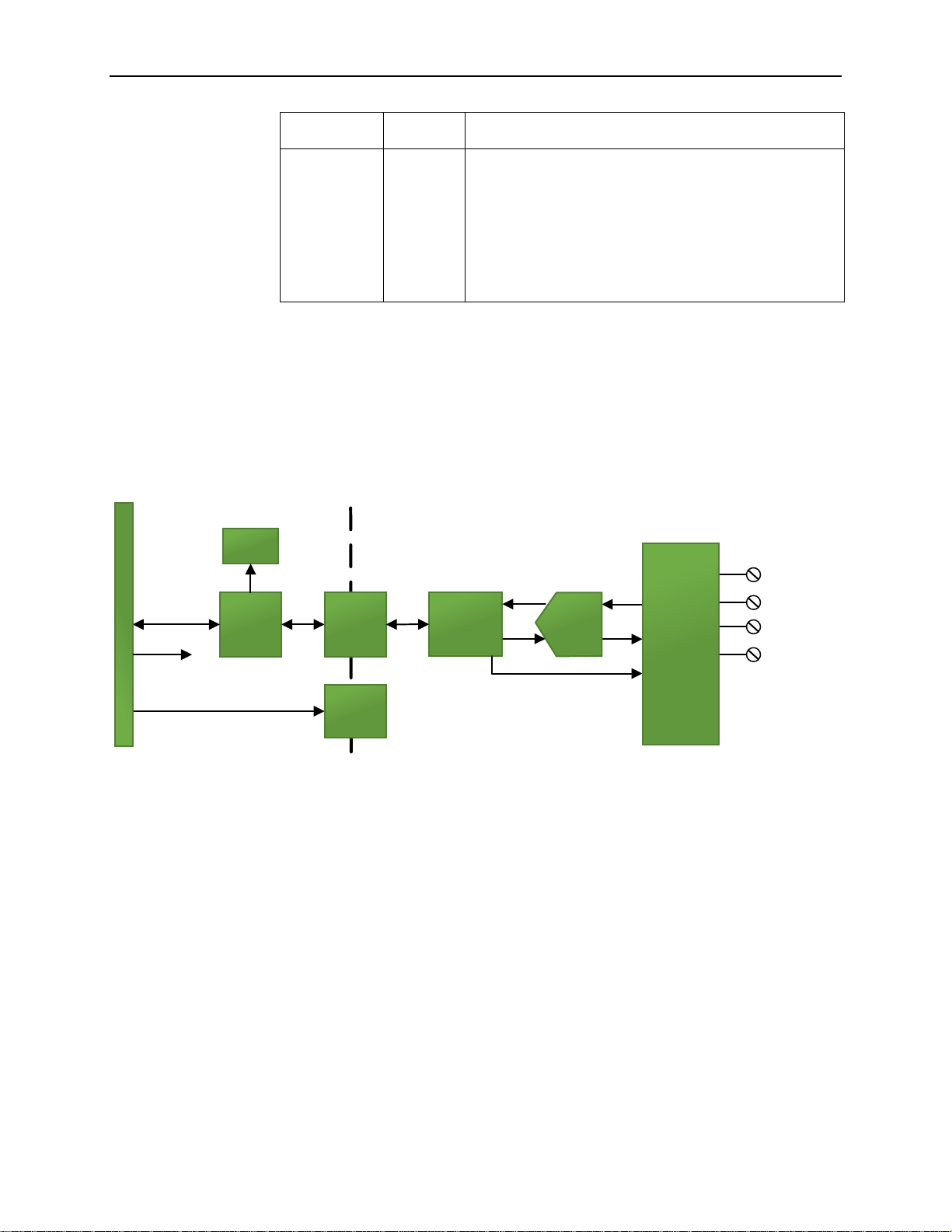
Section 1.5 System Overview
The 2085-IR8-SC module is expected to operate indefinitely. It does not require
periodic maintenance or calibration. The module communicates to the controller
through the bus interface. The module also receives 5 VDC and 24 VDC through
the bus interface.
Block diagram:
Isolator
Isolated
DC-DC
Converter
EXCx
Sense+x
RTNx
SENSE-x
Backplane
ASIC
Backplane
Communication
.
.
.
x8
channels
Processor
50VAC
Working
Reinforced
Isolation
5V DC
24V DC
(used by backplane
circuitry)
Status
Indicator
2085 Backplane
8 Input
Channels
ESD
Protection,
Channel
Multiplexing,
& Signal
Conditioning
RTB pins
A/D
Converter
Page 17

Section 2.1
WARNING
The backplane power and the analog inputs of the device shall only be
supplied by an Isolated Secondary Limited Energy Low Voltage source.
Compliance to
European
Union Directives
Chapter 2
Installation and Wiring
This chapter will cover:
• Compliance to European union directives
• Power requirements
• General considerations
• Installing the module
• Field wiring connections
This product is approved for installation within the European Union and EEA
regions. It has been designed and tested to meet the following directives.
2.1.1 EMC Directive
The 2085-IR8-SC is tested to meet Council Directive 2014/30/EU
Electromagnetic Compatibility (EMC) and the following standards, in whole or
in part, documented in a technical construction file:
• IEC 61000-6-4 Electromagnetic compatibility (EMC)–Part 6-4: Generic
standards–Emission standard for industrial environments
• IEC 61000-6-2 Electromagnetic compatibility (EMC)–Part 6-2: Generic
standards–Immunity for industrial environments
• EN 61131-2 Programable controllers - Part 2: Equipment requirements
and tests
Section 2.2 Power Requirements
The module receives power through the bus interface from the +5 VDC/+24
VDC system power supply, and a 24 VDC field power supply. Both must be
present for the module to operate.
Current rating at + 5 V is 94 mA maximum; for +24 V it is 15 mA maximum.
User's Manual Pub. 0300321-01 Rev. A
Page 18
2-2 Chapter 2: Installation and Wiring
User's Manual Pub. 0300321-01 Rev. A
Power rating is 0.9 Watts maximum:
5 VDC
24 VDC
94 mA
15 mA
Section 2.3 General Considerations
The 2085-IR8-SC module is suitable for use in an industrial environment when
installed in accordance with these instructions. Specifically, this equipment is
intended for use in clean, dry environments Pollution degree 22.
2.3.1 Hazardous Location Considerations
This equipment is suitable for use in Class I, Division 2, Groups A, B, C, D or
non-hazardous locations only. The following WARNING statement applies to
use in hazardous locations.
WARNING
EXPLOSION HAZARD
• Substitution of components may impair suitability for Class I,
Division 2; Class II, Division 2; and Class III, Division 2. Do not
replace components or disconnect equipment unless power has
been switched off or the area is known to be non-hazardous.
• Do not connect or disconnect components unless power has been
switched off or the area is known to be non-hazardous.
• This product must be installed in an enclosure.
• All wiring must comply with N.E.C. article 501-4(b), 502-4(b), or
503-3(b), as appropriate for Class I, Class II, and Class III
equipment.
2.3.2 Prevent Electrostatic Discharge
WARNING
Electrostatic discharge can damage integrated circuits or semiconductors if
you touch I/O expansion port connector pins or the terminal block on the
module. Follow these guidelines when you handle the module:
• Touch a grounded object to discharge static potential.
• Wear an approved wrist-strap grounding device.
• Do not touch the port connector or connector pins.
• Do not touch circuit components inside the module.
• If available, use a static-safe work station.
• When it is not in use, keep the module in its static-shield bag.
2
Pollution Degree 2 is an environment where, normally, only non-conductive pollution occurs except that occasionally
a temporary conductivity caused by condensation is expected.
Page 19
Chapter 2: Installation and Wiring 2-3
User's Manual Pub. 0300321-01 Rev. A
2.3.3 Remove Power
WARNING
Remove power before removing or inserting this module. When you
remove or insert a module with power applied, an electrical arc may occur.
An electrical arc can cause personal injury or property damage by:
• Sending an erroneous signal to your system’s field devices,
causing unintended machine motion.
• Causing an explosion in a hazardous environment.
• Causing an electrical arc. Electrical arcing causes excessive wear
to contacts on both the module and its mating connector and may
lead to premature failure.
2.3.4 Selecting a Location
Reducing Noise
Most applications require installation in an industrial enclosure to reduce the
effects of electrical interference. Analog channels are highly susceptible to
electrical noise. Electrical noise coupled to the analog channels will reduce the
performance (accuracy) of the module. Group your modules to minimize adverse
effects from radiated electrical noise and heat. Consider the following conditions
when selecting a location for the analog module. Position the module:
• Away from sources of electrical noise such as hard-contact switches,
relays, and AC motor drives.
• Away from modules which generate significant radiated heat. Refer to
the module’s heat dissipation specification.
In addition, route shielded, twisted-pair analog input wiring away from any high
voltage I/O wiring.
Section 2.4 Mounting
WARNING
Keeping module free of debris and avoiding overheating:
• Do not remove protective debris strip until after the module and
all other equipment near the module is mounted and the wiring is
complete.
• Once wiring is complete, and the module is free of debris,
carefully remove protective strip.
• Failure to remove strip before operating can cause overheating.
Page 20

2-4 Chapter 2: Installation and Wiring
User's Manual Pub. 0300321-01 Rev. A
2.4.1 Minimum Spacing
Maintain spacing from enclosure walls, wire ways, adjacent equipment, etc.
Allow 50.8 mm (2 in.) of space on all sides for adequate ventilation, as shown:
2.4.2 Parts List
Your package contains one Micro800 Expansion I/O 2085-IR8-SC Module and
one Quick Start Guide.
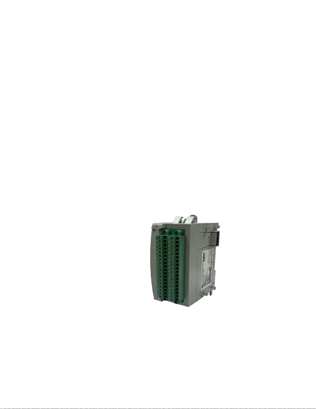
2.4.3 Module Description
Description
Description
1
Mounting screw hole/mounting foot
4
Module interconnect latch
2
Removable Terminal Block (RTB)
5
DIN rail mounting latch
3
RTB hold down screws
6
I/O Status LED
You can choose to wire the expansion I/O module before installing it next to the
controller or wire it once the module is secured in place.
Place the module next to the controller against the panel where you are mounting
it. Make sure the controller and module are spaced properly.
3
2
4
1
6
5
3
3
1
Page 21

Chapter 2: Installation and Wiring 2-5
User's Manual Pub. 0300321-01 Rev. A
NOTE
• This equipment is considered Group 1, Class A industrial
equipment according to IEC/CISPR 11. Without appropriate
precautions, there may be difficulties with electromagnetic
compatibility in residential and other environments due to
conducted and radiated disturbance.
• Be careful when stripping wires. Wire fragments that fall into the
controller could cause damage. Once wiring is complete, make
sure the controller is free of all metal fragments before removing
the protective debris strip.
• Do not wire more than 2 conductors on any single terminal.
• If you insert or remove the expansion I/O module while power is
on, an electrical arc can occur. This could cause an explosion in
hazardous location installations. Be sure that power is removed or
the area is nonhazardous before proceeding.
• Cable length should be less than 10 meters.
2.4.4 Insert Module Next to the Controller
Follow the instructions to insert and secure the expansion I/O module to the
controller:
NOTE
The module expansion may only be mounted horizontally.
NOTE
For environments with greater vibration and shock concerns, use the panel
mounting method, instead of DIN rail mounting.
Mounting Dimensions and DIN Rail Mounting
150 mm (5.91 in.)
44.5 mm (1.75 in.)
Micro850 Controller
2085-IR8-SC
Bus terminator
89 mm
(3.50 in.)
Page 22

2-6 Chapter 2: Installation and Wiring
User's Manual Pub. 0300321-01 Rev. A
You can install the module on DIN rails of dimension 35 mm × 7.5 mm × 1 mm
(EN 50 022-35×7.5), or on a panel.
WARNING
Hazard of intermittent grounding.
This product is grounded through the DIN rail to chassis ground. To
assure proper grounding, use zinc-plated, yellow-chromate steel DIN
rail. Using other DIN rail materials such as aluminum or plastic, that
can corrode, oxidize, or are poor conductors, may result in improper
or intermittent grounding.
Use the correct DIN rail type, and secure DIN rail to mounting surface
approximately every 200 mm (7.8 in.) and use end-anchors appropriately.
1. Before mounting the module on a DIN rail, use a flat-bladed screwdriver
in the DIN rail latch and pry it downwards until it is in the unlatched
position.
2. Hook the top of the DIN rail mounting area of the module onto the DIN
rail, and then press the bottom until the module snaps onto the DIN rail.
3. Push the DIN rail latch back into the latched position. Use DIN rail end
anchors for vibration or shock environments.
4. Snap the module into the module bay.
5. Using a screwdriver, tighten the 10…12 mm (0.39…0.47 in.) M3 self-
tapping screw to torque specifications: 0.25 N-m (2.2 lb-in).
Panel Mounting
The preferred mounting method is to use two M4 (#8) screws per module. Hole
spacing tolerance is ±0.4 mm (0.016 in.). For mounting dimensions, refer to
Micro830, Micro850, and Micro870 Programmable Controllers User Manual
2080-UM002.
To install:
6. Place the module next to the controller against the panel where you are
mounting the module.
7. Mark drilling holes through the mounting screw holes and mounting feet,
and then remove the module.
8. Drill the holes at the markings.
9. Replace the module and mount it. Leave the protective debris strip in
place until you are finished wiring the module, and any other devices.
Page 23

Chapter 2: Installation and Wiring 2-7
User's Manual Pub. 0300321-01 Rev. A
Wiring Diagram
WARNING
Hazard of damage to the terminal connector.
The Spectrum Controls RTB hold down and terminal screws must be
tightened by hand using the guidelines. They must not be tightened using a
power tool. Use a screwdriver of 0.8 × 2 mm and tighten to no more than
0.25 N-m (2.2 lb-in) torque.
Failure to follow these guidelines may result in damage to your connector.
Wire the module using the following images, which explain the layout of the 2row, 18-pin terminal block, and the associated wiring diagrams for the various
input signals and the Micro800 Expansion I/O 2085-IR8 module.
RTB1
Name
1
EXC0
2
SENSE+0
3
RTN0
4
SENSE-0
5
EXC1
6
SENSE+1
7
RTN1
8
SENSE-1
9
NC
10
NC
11
EXC2
12
SENSE+2
13
RTN2
14
SENSE-2
15
EXC3
16
SENSE+3
17
RTN3
18
SENSE-3
RTB2
Name
19
EXC4
20
SENSE+4
21
RTN4
22
SENSE-4
23
EXC5
24
SENSE+5
25
RTN5
26
SENSE-5
27
EXC6
28
SENSE+6
29
RTN6
30
SENSE-6
31
EXC7
32
SENSE+7
33
RTN7
34
SENSE-7
35
NC
36
NC
Page 24

2-8 Chapter 2: Installation and Wiring
User's Manual Pub. 0300321-01 Rev. A
2-wire Res./RTD Input 3-wire Res./RTD Input
RTN
EXC
SENSE+
+
-
SENSE-
RTN
EXC
SENSE+
SENSE-
4-wire Res./RTD Input
RTN
EXC
SENSE+
SENSE-
Terminal Block Input signal descriptions are as follows:
RTB1
Name
Desc.
RTB2
Name
Desc.
1
EXC0
Ch. 0 Excitation Current
19
EXC4
Ch. 4 Excitation Current
2
SENSE+0
Ch. 0 Positive Sense Lead
20
SENSE+4
Ch. 4 Positive Sense Lead
3
RTN0
Ch. 0 Return Current Path
21
RTN4
Ch. 4 Return Current Path
4
SENSE-0
Ch. 0 Negative Sense Lead
22
SENSE-4
Ch. 4 Negative Sense Lead
5
EXC1
Ch. 1 Excitation Current
23
EXC5
Ch. 5 Excitation Current
6
SENSE+1
Ch. 1 Positive Sense Lead
24
SENSE+5
Ch. 5 Positive Sense Lead
7
RTN1
Ch. 1 Return Current Path
25
RTN5
Ch. 5 Return Current Path
8
SENSE-1
Ch. 1 Negative Sense Lead
26
SENSE-5
Ch. 5 Negative Sense Lead
9
NC
No Connect
27
EXC6
Ch. 6 Excitation Current
10
NC
No Connect
28
SENSE+6
Ch. 6 Positive Sense Lead
11
EXC2
Ch. 2 Excitation Current
29
RTN6
Ch. 6 Return Current Path
12
SENSE+2
Ch. 2 Positive Sense Lead
30
SENSE-6
Ch. 6 Negative Sense Lead
13
RTN2
Ch. 2 Return Current Path
31
EXC7
Ch. 7 Excitation Current
14
SENSE-2
Ch. 2 Negative Sense Lead
32
SENSE+7
Ch. 7 Positive Sense Lead
15
EXC3
Ch. 3 Excitation Current
33
RTN7
Ch. 7 Return Current Path
16
SENSE+3
Ch. 3 Positive Sense Lead
34
SENSE-7
Ch. 7 Negative Sense Lead
17
RTN3
Ch. 3 Return Current Path
35
NC
No Connect
18
SENSE-3
Ch. 3 Negative Sense Lead
36
NC
No Connect
Page 25

User's Manual Pub. 0300321-01 Rev. A
Chapter 3
Configuring the 2085-IR8-SC
Using CCW
This chapter covers the following subjects:
• How to use Connected Components Workbench (CCW) and optionally
ModuleConfigConverter.exe software to configure the Module.
• Analog Data and Status settings.
• Data Links settings.
• Setting configuration parameters and associated values.
Section 3.1 Introduction
You use CCW software (v 9.00.00 and above) to configure the 2085-IR8-SC
Expansion I/O Module. Spectrum Controls, Inc. provides a custom configuration
software utility that you may use to provide configuration settings to the profile.
You then send the configuration setup to the module.
Your controller firmware must be at v. 9.011 and above as well.
The Micro850/870 Controller (Bus master) subsystem is located at the left end of
the bus. This subsystem is comprised of:
• Micro800 Controller
• Micro800 Expansion I/O Modules
• 2085-ECR Bus Terminator
Optional:
• 2080-PS120-240VAC Power Supply (separate module or built-in the
main controller).
• 2080 Expansion Modules
• 2085-EP24VDC Expansion Power Supply for Micro870 Controller.
Page 26

3-2 Chapter 3: Configuring the Micro800 Expansion I/O 2085-IR8-SC Using CCW
User's Manual Pub. 0300321-01 Rev. A
Section 3.2 Importing a Profile into CCW Software
You use the module’s add-on-profile to configure your module. The profile is
available in the CCW software. If not available, or a newer revision is released,
see Appendix A about how to manually import a module AOP to CCW.
To view information about the profile:
1. Use RA’s Module Profile Tool 2.0. This tool may be launched from
within CCW by selecting the Module Profile Tool option from the
CCW Tools menu:
2085-IR8-SC
8-Channel
RTD & R Analog Input Module
Micro850/870
Controller
Micro800
Expansion
I/O
Modules
PC Workstation
with CCW Program
and 2085-IR8-SC
RTD
Pt 385/3916, Cu 426,
Ni 618/672, NiFe 518
2080
Expansion
I/O
Modules
Micro800 Expansion I/O Module Backplane
2080
Expansion
I/O module
Backplane
USB/Ethernet
Connection
User
Resistance
150, 500, 1 k, 3 kΩ
Page 27

Chapter 3: Configuring the Micro800 Expansion I/O 2085-IR8-SC Using CCW 3-3
User's Manual Pub. 0300321-01 Rev. A
2. When prompted by Windows User Account Control, to confirm that you
wish to run the program, click Yes button.
If necessary, confirm with the Windows operating system that you wish
to run the software. The Module Profile Tool dialog appears:
3. Select the row showing the module catalog name, and then click the
View button.
The View Module Profile window appears:
The first tab of the window provides the module identity information.
This information is described in greater detail in Module Identity, later
in this section.
4. To view software language availability, module description, and a help
file for the module, click the Resources tab.
Page 28

3-4 Chapter 3: Configuring the Micro800 Expansion I/O 2085-IR8-SC Using CCW
User's Manual Pub. 0300321-01 Rev. A
The Resources tab appears:
The window lists the language chosen for the module, and the module
description. You may also use this tab to access the help file provided for
the module.
5. To view default configuration information, click the Default
Configuration tab:
6. The enabled checkbox shown on the bottom of the tab indicates that the
software provides the service for launching the MCC utility to help you
configure your module. More information is described in Setting
Configuration Parameters Using MCC, later in this section.
Page 29

Chapter 3: Configuring the Micro800 Expansion I/O 2085-IR8-SC Using CCW 3-5
User's Manual Pub. 0300321-01 Rev. A
Section 3.3 2085-IR8-SC Tab on CCW
Before you start, if needed, install the latest version of Rockwell Automation’s
Connected Components Workbench (CCW) Standard Edition.
NOTE
Using the Module Profile Tool to import the 2085-IR8 AOP into CCW
software is necessary only if you are using a CCW version earlier than
11.00.00. For information on manually importing an AOP file, see
Appendix A. For Version 11.00.00 and later, the module is already
available as a selection from the CCW Expansion Modules drop-down
menu:
To add the module to your project, and see its configuration parameters on the
CCW configuration tab:
7. From your CCW project, load the module AOP to a first Available slot
from the Expansion Modules drop-down list.
8. Once the module AOP is loaded, to view the associated variables, click
the Module Catalog Name option.
Page 30

3-6 Chapter 3: Configuring the Micro800 Expansion I/O 2085-IR8-SC Using CCW
User's Manual Pub. 0300321-01 Rev. A
The same variables can also be found on the CCW Global Variables Tab:
9. To view the configuration tab, click the Configuration option:
• Maximum Length. Shows maximum number of words available.
Each word is 16-bit.
Page 31

Chapter 3: Configuring the Micro800 Expansion I/O 2085-IR8-SC Using CCW 3-7
User's Manual Pub. 0300321-01 Rev. A
• Configuration. The textbox lists out the whole module configuration
value.
• Radix. The drop-down menu contains the following number formats
for indicating module configuration value. Options are:
- Hex. Default option. Characters represented as hexadecimal.
Example: 0×7FFF as 32767 in decimal format.
- ASCII: Characters represented as ASCII. Example: \7F\FF
- Binary: Characters represented as 0 and 1. Example:
0111111111111111
- Decimal. Characters represented as decimals. Example:
327673
• Launch. Use to populate the file path field. The file path lets you
enter the file path for opening the MCC utility program to assist you
in configuring the module. Use the Browse ellipse to navigate to
where the utility is stored. Then click the Launch button to start the
utility.
Section 3.4 Setting Configuration Parameters Using MCC
You may create the configuration for each channel using the utility provided by
Spectrum Controls, Inc. You download the utility from the Spectrum Controls
website at www.spectrumcontrols.com.
NOTE
It is recommended that when you generate your configuration, that you
use the Binary Radix selection. If you choose the Decimal Radix, the
utility is unable to work with negative values.
You may create the configuration for each channel using the MCC utility
provided by Spectrum Controls, Inc. You download the utility from the Spectrum
Controls website at https://www.spectrumcontrols.com.
To use the MCC utility:
1. The first time you configure a Spectrum Controls 2085 analog module,
you must provide the file path of the utility to the CCW software.
3
The valid range for the Decimal Radix indication is from 0 to 65535. It does not accept negative values. If
you need to receive negative values, select the Hex Radix option instead.
Page 32

3-8 Chapter 3: Configuring the Micro800 Expansion I/O 2085-IR8-SC Using CCW
User's Manual Pub. 0300321-01 Rev. A
2. Navigate to the CCW Configuration Tab and click in the file path
textbox below the Launch button.
The Browse button appears.
3. Click the button, navigate to the directory where you installed the CCW
program, and select the ModuleConfigConverter tool located in the
Spectrum Tool directory:
Example. C:\Program Files (x86)\Rockwell
Automation\CCW\SpectrumTool
4. To run the tool, click Launch. The Module Config Converter dialog
appears:
5. Select the 2085-IR8-SC module from the drop-down menu, and click
OK:
Page 33

Chapter 3: Configuring the Micro800 Expansion I/O 2085-IR8-SC Using CCW 3-9
User's Manual Pub. 0300321-01 Rev. A
The 2085-IR8-SC Configuration Setup dialog appears:
6. View and specify the following options as needed. See Channel
Configuration Bit locations listed later in this section for details on the
settings for every configuration bit:
• Chan. Lists number of input channel from 0 to 7.
• Enable. Specifies whether to enable use of this channel. Enabled by
default (checkbox enabled).
• Input Type. Specifies which input type to use. Select type from
drop-down list. 100 Ω Platinum 385 is default:
• Data Format. Specifies which data format to use for reporting input
values. Default is Engineering Units X1:
• Temp Units. Specifies the temperature units the module reports in
Centigrade or Fahrenheit. Default is Centigrade:
Page 34

3-10 Chapter 3: Configuring the Micro800 Expansion I/O 2085-IR8-SC Using CCW
User's Manual Pub. 0300321-01 Rev. A
• Connection. Defines connection type. Default is 3-Wire With
Compensation:
• Filter. Specifies which filter to use. Default is 17 Hz.
• Open Circuit Response. Specifies how to respond to an open circuit
condition. Default is Upscale4.
• Process Alarm . Specifies whether a warning on under- or over-
range detection (from user-defined values) is turned on for the
channel, disabled, or enabled for both alarm and latch.
• Process Alarm High. Specify over range value of a user-defined
value for the module to monitor.
• Process Alarm Low. Specify under range value of a user-defined
pair of high and low values for the module to monitor.
• Channel Bias. Specifies individual channel bias values. Default bias
is 0. Range may be -32768 to 32767.
4
The Disable option is only available for voltage measurement.
Page 35

Chapter 3: Configuring the Micro800 Expansion I/O 2085-IR8-SC Using CCW 3-11
User's Manual Pub. 0300321-01 Rev. A
7. When finished making selections, click Generate.
The Configuration Text dialog appears with your configuration settings
for all the channels.
You can manually copy the settings and paste it to the textbox of the
CCW Configuration tab5.
8. To automatically copy the generated settings into the textbox of the
CCW Configuration tab, have the textbox visible on the monitor screen,
and then click Copy to CCW button5.
9. The utility copies the configuration settings and shows it inside the
textbox.
10. Download the CCW project to controller and start to run the module
operation.
5
It is recommended that before manually or automatically pasting your configuration settings to the textbox
of the CCW Configuration tab, be sure to select the Hex Radix indication on both software packages. The
CCW software is unable to receive negative values under Decimal Radix indication.
Page 36

3-12 Chapter 3: Configuring the Micro800 Expansion I/O 2085-IR8-SC Using CCW
User's Manual Pub. 0300321-01 Rev. A
Section 3.5 Software Information
3.5.1 Software Versioning
The software version tracks major and minor revisions for end users.
The shipped software version begins at version 1.1.
Once released, the major revision is typically incremented if new features are
introduced to the product. Otherwise only the minor revision is incremented.
3.5.2 Software Updates
In-field updating of the software by the end user is not supported.
3.5.3 Startup and Factory Default Conditions
After the module boots and before the initial configuration is received, the
module holds the default configuration as specified in the Configuration
Assembly. There is no input data communication and no signal outputting before
the controller goes into run mode. The default configuration is for all channels
enabled in the 3-wire, 100PT385 range with the 17 Hz filter in Engineering ×1
units.
3.5.4 PLC Interfaces
The 2085 platform treats all data on an I/O module as a member of a named
Array of Words.
Module Identity
The following values will be stored in the Vendor ID, Product_Type,
Product_Code, Series_Rev, and Mod_Features arrays:
Parameter
Description
Vendor ID
58 (Spectrum Controls) [0×03A]
Product Type
10 (Analog) [0×0A]
Product Code
119 [0×77]
Series Rev
50208 [0×C420] (First release revision
is 1.1)
Module Catalog String
2085-IR8-SC
3.5.5 Connection Types and Assembly Sizes
The size of each assembly is listed in the table below. Each word takes 2 bytes.
These values are stored in the Mod_Size array:
Table
Size (words)
Configuration Assembly
32
Input Assembly
14
Output Assembly
1
Page 37

Chapter 3: Configuring the Micro800 Expansion I/O 2085-IR8-SC Using CCW 3-13
User's Manual Pub. 0300321-01 Rev. A
3.5.6 Configuration Table
The configuration table size for the module is 32 words. Each Configuration Bit
is formed in an unsigned 16-bit Data Type. Each value input is assigned to a
signed 16-bit Data Type with a range of -32768 to +32767.
Word Index
Tag Name for 2085-IR8-SC (32 Words)
Config. 0
Ch0 Configuration Bits
Config. 1
Ch0 Process Alarm High Value
Config. 2
Ch0 Process Alarm Low Value
Config. 3
Ch0 Channel Bias Value
…
Ch1 to Ch6 Configurations
Config. 28
Ch7 Configuration Bits
Config. 29
Ch7 Process Alarm High Value
Config. 30
Ch7 Process Alarm Low Value
Config. 31
Ch7 Channel Bias Value
3.5.7 Channel Configuration Bit Location Data
Feature
Option
Decimal
Value
Configuration Bit
15
14
13
12
11
10 9 8 7 6 5 4 3 2 1 0
Channel
Enable
Enable
0
0
Disable
1
1
Input Type
Pt 385 100 Ω
0 0 0 0 0
Pt 385 200 Ω
1 0 0 0 1
Pt 385 500 Ω
2 0 0 1 0
Pt 385 1000 Ω
3 0 0 1 1
Pt 3916 100 Ω
4 0 1 0 0
Pt 3916 200 Ω
5 0 1 0 1
Pt 3916 500 Ω
6 0 1 1 0
Pt 3916 1000 Ω
7 0 1 1 1
Cu 426 10 Ω
8 1 0 0 0
Ni 618 100 Ω
9 1 0 0 1
Ni 672 120 Ω
10 1 0 1 0
NiFe 518 604 Ω
11 1 0 1 1
150 Ω
12 1 1 0 0
500 Ω
13 1 1 0 1
1000 Ω
14 1 1 1 0
3000 Ω
15 1 1 1 1
Data Format
Engineering Units ×1
0
0
0
Engineering Units ×10
1 0 1
Page 38

3-14 Chapter 3: Configuring the Micro800 Expansion I/O 2085-IR8-SC Using CCW
User's Manual Pub. 0300321-01 Rev. A
Feature
Option
Decimal
Value
Configuration Bit
15
14
13
12
11
10 9 8 7 6 5 4 3 2 1 0
Raw/Proportional Data
2 1 0
Percentage Range
3 1 1
Temperature
Scale6
°C
0
0
°F 1 1
Connection
Method
3-wire with compensation
0
0
0
4-wire
1 0 1
2-wire
2 1 0
Invalid
NA
NA
Filter
Frequency
17 Hz
0
0
0 4 Hz
1 0 1
62 Hz
2 1 0
470 Hz
3 1 1
Open Circuit
Detection
Upscale
0 0
0 Downscale
1 0 1
Zero
2 1 0
Disable
3 1 1
Process Alarm
& Latching
Both Disabled
0 0 0 Alarm Enabled Only
1 0 1
Alarm & Latching Enabled
2 1 0
Invalid
NA
NA
3.5.8 Channel Configuration Values
The module provides 3 words for you to enter each channel’s Process Alarm
High value, Process Alarm Low value, and Channel Bias value. Each value is
specified as a full-scale integer which starts from -32768 to +32767. See the
related information in the Process Alarm and Latching feature and the Channel
Bias sections later in this manual.
Feature
Type
Length
Process Alarm High
INT
1 word
Process Alarm Low
INT
1 word
Channel Bias
INT
1 word
6
Effective only when the “Input Type” of the selected input channel is configured to use “RTD”
type and EU×1 or EU×10 Data Format.
Page 39

Chapter 3: Configuring the Micro800 Expansion I/O 2085-IR8-SC Using CCW 3-15
User's Manual Pub. 0300321-01 Rev. A
3.5.9 Input Table
The input table size for the module is 16 words. Each channel data is assigned to
a signed 16-bit data byte and displays value between -32768 to +32767. The
actual display value is clamped by each Input Type limit, or by the signed 16-bit
data byte, whichever comes first. Other status indication bits, fault bits, and
software revision information are in an unsigned 16-bit Data Type.
Word
Index
Tag Name for
2085-IR8-SC (14 Words)
AI_00
Ch0 Data
AI_01
Ch1 Data
AI_02
Ch2 Data
AI_03
Ch3 Data
AI_04
Ch4 Data
AI_05
Ch5 Data
AI_06
Ch6 Data
AI_07
Ch7 Data
AI_08
Ch1 Status
Ch 0 Status
AI_09
Ch3 Status
Ch 2 Status
AI_10
Ch5 Status
Ch 4 Status
AI_11
Ch7 Status
Ch 6 Status
AI_12
Module Status
AI_13
Software Revision
3.5.10 Input Bit and Value Allocation
Status &
Reading
Indication
Word
Index
High Byte
Low Byte
Bits
15
14
13
12
11
10 9 8 7 6 5 4 3 2 1 0
Ch0 Data
AI_00
Signed INT
Ch1 Data
AI_01
Signed INT
Ch2 Data
AI_02
Signed INT
Ch3 Data
AI_03
Signed INT
Ch4 Data
AI_04
Signed INT
Ch5 Data
AI_05
Signed INT
Ch6 Data
AI_06
Signed INT
Ch7 Data
AI_07
Signed INT
Ch 1 & 0
Status
AI_08
-
OC
OR
UR
PAH
PAL
ADC
FT1 - OC
OR
UR
PAH
PAL
ADC
FT0
Ch 3 & 2
Status
AI_09
-
OC
OR
UR
PAH
PAL
ADC
FT3 - OC
OR
UR
PAH
PAL
ADC
FT2
Ch 5 & 4
Status
AI_10
-
OC
OR
UR
PAH
PAL
ADC
FT5 - OC
OR
UR
PAH
PAL
ADC
FT4
Page 40

3-16 Chapter 3: Configuring the Micro800 Expansion I/O 2085-IR8-SC Using CCW
User's Manual Pub. 0300321-01 Rev. A
Status &
Reading
Indication
Word
Index
High Byte
Low Byte
Bits
15
14
13
12
11
10 9 8 7 6 5 4 3 2 1 0
Ch 7 & 6
Status
AI_11
-
OC
OR
UR
PAH
PAL
ADC
FT7 - OC
OR
UR
PAH
PAL
ADC
FT6
Module &
Channel
Fault
AI_12
MF
CAL
SN
Unused
- - - - - - -
-
Software
Revision
AI_13
Signed INT
3.5.11 Module and Channel Fault Bit and Value Description
Module and Channel Fault
Name
Description
Unused
Bits marked as Not Used are set to 0.
CAL
Invalid Cal Data
The stored calibration data or checksum is corrupt or invalid.
The module must be factory calibrated before it will operate normally.
SN
Invalid Serial Number Data
The stored serial number checksum is corrupt or invalid.
The module must be factory calibrated before it will operate normally.
MF
Module Fault
Set as global fault if any channel fault.
3.5.12 Software Revision
Name
Description
Displayed as an integer value. Example: 1101 is version 1.1.01
3.5.13 Channel Status
Channel Status
Name
Description
FT<n>
Channel Fault <Channel>
Channel Fault bit. If a bit is set (1) then there is an error associated with that
input channel.
ADC<n>
ADC Communication Failure or PGA Connection Failure
When set to 1, indicates there is a channel ADC communication failure or PGA
connection error. This is a hardware fault.
PAL<n>
Process Alarm Low
When set to 1, indicates the channel input value is less than or equal to the
user-defined Process Alarm Low Value in the configuration table.
Page 41

Chapter 3: Configuring the Micro800 Expansion I/O 2085-IR8-SC Using CCW 3-17
User's Manual Pub. 0300321-01 Rev. A
Channel Status
Name
Description
PAH<n>
Process Alarm High
When set to 1, indicates the channel input value is greater than or equal to the
user-defined Process Alarm High Value in the configuration table.
UR<n>
Under Range
When set to 1, indicates the channel input reading is less than or equal to the
minimum point of the selected Input Type range or the Data Type low limit,
-32768.
OR<n>
Over Range
When set to 1, indicates the channel input reading is greater than or equal to the
maximum point of the selected Input Type range or the Data Type high limit,
+32767.
OC<n>
Open Circuit
When set to 1, indicates the channel connection on the terminal block is open.
Unused
Bits marked as Not Used are set to 0.
3.5.14 Channel Data
Channel Data
Length
Name
Description
1 word
Ch<n>
Data
Channel Input Data <Channel>
The Data Type for the Channel Input Data is a signed 16-bit integer. The
integer ranges from -32768 to +32767.
See additional indication information about the Under/Over Range Alarm
feature and information about the Open Circuit Detection.
3.5.15 Output Table
The output table size for the module is 1 word. The 16 bits in each word are the
control bits on clearing the Low and High Process Alarm Latches for 8 channels
a group. To operate the control bits, see the information about the Process Alarm
and Latching feature.
Word
Index
Tag Name for
2085-IR8-SC (1 Word)
AO_00
Ch 7:0 Clear High/Low Process
Alarm Latch
Page 42

3-18 Chapter 3: Configuring the Micro800 Expansion I/O 2085-IR8-SC Using CCW
User's Manual Pub. 0300321-01 Rev. A
3.5.16 Output Bit Allocation
Process
Alarm
Latch
Word
Index
High Byte
Low Byte
Bits
15
14
13
12
11
10 9 8 7 6 5 4 3 2 1 0
Ch 7:0
AO_0
0 CH7
CL
7
CH
6
CL
6
CH
5
CL
5
CH
4
CL
4
CH
3
CL
3
CH
2
CL
2
CH
1
CL
1
CH
0
CL
0
3.5.17 Output Bit Description
AO_00: Clear High/Low Process Alarm Latches
Bit
Name
Description
Even
CL<n>
Clear Low Process Alarm Latch
0: Normal Operation
1: Clear low process alarm latch
Odd
CH<n>
Clear High Process Alarm Latch
0: Normal Operation
1: Clear high process alarm latch
Section 3.6 Product Features
The following sections provide information on user-configurable parameters.
3.6.1 Data Format
The Data Format is used to define the display scale of the measured input data.
Each channel can display different formats, based on user-defined choices. This
module provides four options for channel input display:
Index
Data Format
Note
0
Engineering Unit ×1
Default
1
Engineering Unit ×10
2 Raw/Proportional
3
Percentage Full Scale
3.6.2 Input Type
The maximum range to display a measured input data in the input table is from 32768 to +32767 as a signed 16-bit integer. The actual range is scaled to fit the
selected Input Type. For example, the valid range for Pt 385 types is from -200°C
to 850°C. In Engineering Unit ×1 format, the valid display range is from -2000 to
8500, which provides the resolution down to 1 decimal place.
Page 43

Chapter 3: Configuring the Micro800 Expansion I/O 2085-IR8-SC Using CCW 3-19
User's Manual Pub. 0300321-01 Rev. A
The defined, data display resolution for each input type is listed in the following
table. If the Data Format of the Input Type supports the resolution up to after the
decimal point, the fractional part of the input reading is shifted up to display in
integers:
Input Type
EUx1
EUx10
Raw Prop
Percentage
RTD
1 decimal point (DP)
Integer
56K
10 K
Resistance
2 DP for 150 Ω
1 DP for 500/1 K/3 K Ω
1 DP for 150 Ω
Integer for 500/1 K/3 K
Ω
10.5 K
In Engineering Unit ×10 format, the valid display range is from -200 to 850 in
integers. The Raw/Proportional format provides 65 K resolution based on the
valid range in EU×1 format of the selected Input Type. The same scaling
requirement applies to the Percentage format, which has 10 K resolution.
Index
Selection
Note
0
Pt 385 100 Ω
Default
1
Pt 385 200 Ω
2
Pt 385 500 Ω
3 Pt 385 1000 Ω
4 Pt 3916 100 Ω
5 Pt 3916 200 Ω
6 Pt 3916 500 Ω
7 Pt 3916 1000 Ω
8 Cu 426 10 Ω
9 Ni 618 100 Ω
10
Ni 672 120 Ω
11
NiFe 518 604 Ω
12
150 Ω
13
500 Ω
14
1000 Ω
15
3000 Ω
Range points and limits for Input Types are provided in the following table. For
each Input Type, the limits are set to the maximum and minimum values of its
range:
Input Type
Input Value
Condition
EU x1
EU x10
Raw Prop
Percentage
RTD
100 Ω
Pt
0.385
850.00 °C
High Limit
8500
850
32767
10000
850.00 °C
High Range
8500
850
32767
10000
-200.00 °C
Low Range
-2000
-200
-32768
0
-200.00 °C
Low Limit
-2000
-200
-32768
0
200 Ω
850.00 °C
High Limit
8500
850
32767
10000
Page 44

3-20 Chapter 3: Configuring the Micro800 Expansion I/O 2085-IR8-SC Using CCW
User's Manual Pub. 0300321-01 Rev. A
Input Type
Input Value
Condition
EU x1
EU x10
Raw Prop
Percentage
RTD
Pt
0.385
850.00 °C
High Range
8500
850
32767
10000
-200.00 °C
Low Range
-2000
-200
-32768
0
-200.00 °C
Low Limit
-2000
-200
-32768
0
500 Ω
Pt
0.385
850.00 °C
High Limit
8500
850
32767
10000
850.00 °C
High Range
8500
850
32767
10000
-200.00 °C
Low Range
-2000
-200
-32768
0
-200.00 °C
Low Limit
-2000
-200
-32768
0
1000 Ω
Pt
0.385
850.00 °C
High Limit
8500
850
32767
10000
850.00 °C
High Range
8500
850
32767
10000
-200.00 °C
Low Range
-2000
-200
-32768
0
-200.00 °C
Low Limit
-2000
-200
-32768
0
100 Ω
Pt
0.3916
630.00 °C
High Limit
6300
630
32767
10000
630.00 °C
High Range
6300
630
32767
10000
-200.00 °C
Low Range
-2000
-200
-32768
0
-200.00 °C
Low Limit
-2000
-200
-32768
0
200 Ω
Pt
0.3916
630.00 °C
High Limit
6300
630
32767
10000
630.00 °C
High Range
6300
630
32767
10000
-200.00 °C
Low Range
-2000
-200
-32768
0
-200.00 °C
Low Limit
-2000
-200
-32768
0
500 Ω
Pt
0.3916
630.00 °C
High Limit
6300
630
32767
10000
630.00 °C
High Range
6300
630
32767
10000
-200.00 °C
Low Range
-2000
-200
-32768
0
-200.00 °C
Low Limit
-2000
-200
-32768
0
1000 Ω
Pt
0.3916
630.00 °C
High Limit
6300
630
32767
10000
630.00 °C
High Range
6300
630
32767
10000
-200.00 °C
Low Range
-2000
-200
-32768
0
-200.00 °C
Low Limit
-2000
-200
-32768
0
10 Ω
Cu
0.426
260.00 °C
High Limit
2600
260
32767
10000
260.00 °C
High Range
2600
260
32767
10000
-100.00 °C
Low Range
-1000
-100
-32768
0
-100.00 °C
Low Limit
-1000
-100
-32768
0
100 Ω
Ni
0.618
260.00 °C
High Limit
2600
260
32767
10000
260.00 °C
High Range
2600
260
32767
10000
-100.00 °C
Low Range
-1000
-100
-32768
0
-100.00 °C
Low Limit
-1000
-100
-32768
0
Page 45

Chapter 3: Configuring the Micro800 Expansion I/O 2085-IR8-SC Using CCW 3-21
User's Manual Pub. 0300321-01 Rev. A
Input Type
Input Value
Condition
EU x1
EU x10
Raw Prop
Percentage
RTD
120 Ω
Ni
0.672
260.00 °C
High Limit
2600
260
32767
10000
260.00 °C
High Range
2600
260
32767
10000
-80.00 °C
Low Range
-800
-80
-32768
0
-80.00 °C
Low Limit
-800
-80
-32768
0
604 Ω
Ni-Fe
0.518
200.00 °C
High Limit
2000
200
32767
10000
200.00 °C
High Range
2000
200
32767
10000
-100.00 °C
Low Range
-1000
-100
-32768
0
-100.00 °C
Low Limit
-1000
-100
-32768
0 Input Type
Input Value
Condition
EU x1
EU x10
Raw Prop
Percentage
Resistance
0-150 Ω
150.00 Ω
High Limit
15000
1500
32767
10000
150.00 Ω
High Range
15000
1500
32767
10000
0.00 Ω
Low Range
0 0 -32768
0
0.00 Ω
Low Limit
0 0 -32768
0
0-500 Ω
500.00 Ω
High Limit
5000
500
32767
10000
500.00 Ω
High Range
5000
500
32767
10000
0.00 Ω
Low Range
0 0 -32768
0
0.00 Ω
Low Limit
0 0 -32768
0
0-1000 Ω
1000.00 Ω
High Limit
10000
1000
32767
10000
1000.00 Ω
High Range
10000
1000
32767
10000
0.00 Ω
Low Range
0 0 -32768
0
0.00 Ω
Low Limit
0 0 -32768
0
0-3000 Ω
3000.00 Ω
High Limit
30000
3000
32767
10000
3000.00 Ω
High Range
30000
3000
32767
10000
0.00 Ω
Low Range
0 0 -32768
0
0.00 Ω
Low Limit
0 0 -32768
0
3.6.3 Channel Bias
The module provides a signed 16-bit integer for user to enter a channel bias value
in the configuration table. It can be used to adjust the channel input reading if the
inserted Input Type sensor has measurement offset. The available range is from 32768 to +32767. The scaling formula with the channel bias applied is:
Where:
is the final scaled reading shown in the input table.
Page 46

3-22 Chapter 3: Configuring the Micro800 Expansion I/O 2085-IR8-SC Using CCW
User's Manual Pub. 0300321-01 Rev. A
is the gain:
The User High/Low Limit value is based on the selected Input Type and
the selected Data Format. The Actual High/Low Limit value used is the
actual limit of the selected Input Type without scaling. For example, if Pt
385 type and EU×1 are selected in the configuration table, the gain will
be 10 = (8500 - (-2000)) / (850 – (-200)), m = 10.
is the ADC signal data acquired at the terminal block and converted to
the corresponding Data Format.
If you have an RTD input, this is the actual temperature in degree C.
The firmware reads in the ADC data count. Next, the data count is
converted to the resistor value in ohms based on the gain setting of the
ADC and the setting of the 2-wire, or 3-wire; the resistor value is then
converted to temperature in degree C based on the RTD curve
specification.
is the offset: .
is an offset in integer format.
The Channel Bias value is only applied to the raw measured value. It will
not be applied to shift the minimum and the maximum points and the
limits of the selected Input Type range. If the final channel input reading
is equal to or goes beyond the minimum or the maximum point of the
selected Input Type range, a Channel Fault and an Over/Under Range
Fault bits will be set in the input table.
3.6.4 Channel Temperature
The module provides a feature to select the temperature display unit for each
channel input reading if the channel is configured to use RTD measurement with
EU×1 or EU×10 Data Format used. Temperature is not used if the channel is
being used to run resistance measurements, or a non-engineering unit data format
is selected.
Index
Unit
Note
0
ºC
Default
1
ºF
3.6.5 Connection Method
The default option is used when the 3-wire RTD or resistance device is
connected. The module will run additional compensation to cancel out the leadwire resistance value. The next option provides more accurate measurement
when the connected RTD or resistance device is a 4-wire type. The last option
can be used to measure the value across the main resistance load plus the doubled
lead-wire resistance value if the 2-wire RTD or resistance device is connected.
Index
Connection Method
Note
0
3-wire with Compensation
Default
1
4-wire
Page 47

Chapter 3: Configuring the Micro800 Expansion I/O 2085-IR8-SC Using CCW 3-23
User's Manual Pub. 0300321-01 Rev. A
Index
Connection Method
Note
2
2-wire
3
Invalid
3-Wire Method
When using the 3-wire measurement with one-side sense-wire connected, two
measurements will be executed. The first measurement acquires the reading
across the main resistance load plus the doubled lead-wire resistance value. The
acquisition rate of this measurement is based on the channel scan rate. The
second measurement acquires the reading across the main resistance load plus the
single lead-wire resistance value through the one-side sense-wire. This
measurement is triggered by a microprocessor timer happens every 60 seconds.
If any open wires happen when using this option, the timer will be reset and both
measurements will happen sequentially. Until all the open circuit conditions are
resolved, the acquisition timing of the secondary measurement will be reset back
to the 6-second timeframe. Below are the steps on running 3-wire measurement
with compensation.
Measurement I:
Measurement II:
Where is the injected excitation current.
Calculation:
Where
is the previous measured lead-wire value triggered by the
timer.
4-Wire Method
When using the 4-wire measurement with two-side sense-wire pair connected,
the only required measurement is to measure the voltage drop across the main
resistance load. It will be converted to the corresponding temperature reading or
resistance value based on the selected Input Type. The data acquisition is
executed periodically based on the channel scan rate.
Single Measurement:
2-Wire Method
When using the 2-wire measurement with no sense-wire connected, the measured
voltage drop is across the main resistance load plus the doubled lead-wire
resistance value. No lead-wire resistance compensation is executed on this
option. The data acquisition is also executed periodically based on the channel
scan rate.
Page 48

3-24 Chapter 3: Configuring the Micro800 Expansion I/O 2085-IR8-SC Using CCW
User's Manual Pub. 0300321-01 Rev. A
Single Measurement:
A configuration error is reported if an invalid Connection Method option is
entered in the configuration table.
When the 3-wire measurement with compensation option is enabled, using a
faster ADC filter means the channel input reading becomes noisy. If the second
measurement value is bigger than the first measurement, the lead wire value is
clipped to zero.
3.6.6 Input ADC Filter
This configuration parameter allows you to select a filter setting that attenuates
the input signal beginning at the specified frequency.
The module applies the filter setting to each input channel in sequence during
data acquisition.
Index
Filter (Hz)
Note
0
17
Default
1 4
2
62
3
470
3.6.7 Open Circuit Detection
The open circuit detection feature alerts you to a channel open circuit condition
by selecting the open circuit behavior option in the configuration table to display
a high limit, low limit, or zero data value for the appropriate channel(s) in the
input table. Open circuit detection may also be disabled for any or all channels.
Index
Open Circuit Detection
Note
0
Upscale
Default
1
Downscale
2 Zero
3 Disable
3.6.8 Stimulus/Response Sequences
Once the module receives the configuration, the channel open circuit detection
will be activated on the channel with the feature enabled.
• In 2-wire or 3-wire mode, open circuit detection is achieved during
normal data acquisition. There is no additional time added for open
circuit detection. 2-wire mode open circuit detection and 3-wire primary
pair open circuit detection occur on every scan.
• When the 3-wire excitation wire is open, it causes the secondary pair to
open. This results in both lead and excitation wire detection by the
software. In this instance, the open excitation wire is immediately
Page 49

Chapter 3: Configuring the Micro800 Expansion I/O 2085-IR8-SC Using CCW 3-25
User's Manual Pub. 0300321-01 Rev. A
detected, but it takes 6 to 10 seconds to detect that the excitation wire is
reconnected.
• 3-wire lead resistance is measured at 60-seconds intervals; 3-wire lead
open circuit is also detected once every 60 seconds.
• 3-wire lead resistance needs the following conditions present to be
measured at a faster rate than once every 6 seconds. These conditions are
not considered normal conditions. Once any of these conditions is
removed, lead wire returns to being measured at the rate of once every 60
seconds.
- When any channel has the lead wire open, and open circuit
detection is enabled, lead wire is measured once every 6 seconds
until there is no longer an open wire on any of the channels.
- If a previous lead wire measurement and the current lead wire
measurement difference is more than 0.5 ohms, the lead wire is
measured once every 6 seconds until the read difference between
the two is less than 0.5 ohms.
- If measured lead wire resistance is larger than 25 ohms, lead
wire is measured once every 6 seconds until it is less than 25
ohms.
- In the above cases, it takes about 6 to 10 seconds to detect the
lead wire open or to recover.
• In 4-wire mode, open circuit detection takes place on a periodic basis,
every 5 seconds, alternating between the primary wire pair and the
secondary wire pair, by temporarily enabling the PGA burnout current
and initiating an ADC conversion at the fastest filter frequency (470 Hz).
This open circuit detection also adds about 23 ms delay per channel, on
top of normal scan time. If all channels are configured as 4-wire mode
and enabled, there will be an additional 184 ms scan time added for open
circuit detection once every 5 seconds. Depending on the filter setting,
any open wire in 4-wire mode is detected within 5 to 15 seconds.
• The previous measurement remains in the input table during the open
circuit detection procedure (that is, the measurement value with the
burnout current enabled is not reported).
• Within the period of an open circuit condition, transitional data may be
reported before the open circuit status bit is set.
Each channel has its own status bits to indicate open circuit fault in the input
table. Below are the cases on handling open circuit condition based on the Open
Circuit Detection selection:
• For the Upscale option, the channel input reading is set to the high limit
point based on the selected Input Type and Data Format. The Channel
Fault bit and the OC bit are set.
• For the Downscale option, the channel input reading is set to the low
limit point based on the selected Input Type and Data Format. The
Channel Fault bit and the OC bit are set.
• For the Zero option, the channel input reading is set to 0 no matter what
Input Type and Data Format is configured. The Channel Fault bit and the
OC bit are set.
Page 50

3-26 Chapter 3: Configuring the Micro800 Expansion I/O 2085-IR8-SC Using CCW
User's Manual Pub. 0300321-01 Rev. A
• For the Disable option, an open circuit condition is not reported. Also,
the periodic open circuit detection does not take place.
• The Channel Fault bit and the OC bit are cleared once the open circuit
condition on the channel has been resolved. The time to update the bit
status is controlled by the 3-second or the module scan rate, whichever
takes longer.
• An open circuit condition may also be triggered by feeding channel input
resistance or temperatures well beyond the defined limit values indicated
in the Points and Limits for Input Type.
3.6.9 Process Alarm and Latching
The Process Alarm feature allows you to enter a pair of user-defined high and
low values for the module to monitor between the channel input reading. The
maximum range you may enter is based on the limits of the selected Input Type
and the Data Format. This alarm feature can also be used as an Over or Under
Input Type Limit alarm. Once the channel input reading is equal to, or
greater/less than, the user-defined value, the corresponding channel Process
Alarm status bit is set in the input table.
The lowest value for the Process Alarm Low Value you can set is the low limit of
the selected Input Type. The same requirement applies to the highest value for
the Process Alarm High Value. It can be set only to the high limit of the selected
Input Type.
The Process Alarm Latching decides whether the status bit is to be cleared
automatically or kept latched until manual cleanup is triggered by a user or the
ladder software. The latching feature is useful for capturing whenever the
channel input reading has reached, or exceeded, the user-defined value.
The latch can be cleared by making a bit value transition on the control bit in the
output table.
Index
Process Alarm &
Latching
Note
0
Disable Both
Default
1
Enable Alarm Only
2 Enable Both
3 Invalid
The firmware reports a configuration error if an invalid Process Alarm option is
entered in the configuration table:
• If Option 0 is selected, both the Process Alarm and Latching
functionality are disabled, and the validation on the channel Low and
High Process Alarm Values is ignored.
• If Option 1 or 2 is selected, the firmware reports a configuration error if
any Process Alarm value set in the configuration table is invalid as
follows:
- The Process Alarm Low Value is equal to, or greater than, the
Process Alarm High Value.
- The Process Alarm Low Value is less than the low limit of the
selected Input Type.
Page 51

Chapter 3: Configuring the Micro800 Expansion I/O 2085-IR8-SC Using CCW 3-27
User's Manual Pub. 0300321-01 Rev. A
- The Process Alarm High Value is greater than the high limit of
the selected Input Type.
The firmware sets the Process Alarm Low status bit in the Channel
Status byte and the Channel Fault bit when the channel input reading is
equal to, or less than, the user-defined Process Alarm Low Value entered
in the configuration table.
The firmware sets the Process Alarm High status bit in the Channel
Status byte and the Channel Fault bit when the channel input reading is
equal to, or greater than the user-defined Process Alarm High Value
entered in the configuration table.
If Option 1 is selected,
• The module automatically clears the Process Alarm Low status bit in the
Channel Status byte and its Channel Fault bit when the channel input
reading is greater than the user-defined Process Alarm Low Value
entered in the configuration table.
• The module automatically clears the Process Alarm High status bit in the
Channel Status byte and its Channel Fault bit when the channel input
reading is less than the user-defined Process Alarm High Value entered
in the configuration table.
If Option 2 is selected, latching operates as follows:
• Once the channel Process Alarm Low or High status bit is set as latched,
it is not be cleared even when the channel input reading is no longer:
- equal to, or less than, the user-defined Process Alarm Low Value
OR
- equal to, or greater than, the user-defined Process Alarm High
Value.
• To clear the channel Process Alarm High or Low status bits when both of
the following conditions are satisfied:
- The channel input reading is no longer
▪ equal to, or less than, the user-defined Process Alarm
Low Value
OR
▪ equal to, or greater than, the user-defined Process Alarm
High Value
- The corresponding Clear Low or High Process Alarm Latch bit
in the output table has a value transition from 0 to 1.
3.6.10 Under/Over Range Alarms
An Under Range or Over Range alarm is set if the channel input reading reaches
or exceeds the normal operating range. The alarm is not latched; if the reading
goes back into normal operating range, the alarm is automatically cleared. This
feature applies to all input types.
The Under Range and Over Range status bits are defined in the Channel Bit and
value allocation of the Input Table.
• When the channel input reading is equal to, or less than, the minimum
point of the selected Input Type range, the Channel Under Range status
bit and the Channel Fault bit are set. If the channel input reading reaches
Page 52

3-28 Chapter 3: Configuring the Micro800 Expansion I/O 2085-IR8-SC Using CCW
User's Manual Pub. 0300321-01 Rev. A
the Input Type low limit or less, the channel input reading is clamped at
that low limit value.
• When the channel input reading is equal to or greater than the maximum
point of the selected Input Type range, the Channel Over Range status bit
and the Channel Fault bit are set. If the channel input reading reaches the
Input Type high limit or greater, the channel input reading is clamped at
the high limit value.
• The channel Under or Over range status bits is cleared when the channel
input reading is greater than the minimum point or less than the
maximum point of the selected Input Type range.
3.6.11 ADC Alarm
When each input channel is acquiring its channel data in sequence on the
corresponding ADC measurement circuit, to ensure the validity of the data
reading, the ADC and PGA IDs and the signal reading are validated for reporting
potential acquisition failure in time.
If there is a communication failure, the channel ADC Fault bit and the Channel
Fault bit are set in the input table. This can happen when the ESD environment is
out of the hardware specification tolerance or the hardware connection on the
ADC and PGA component is damaged.
To clear the fault bit, cycle power the module. If the fault fails to clear, please
send the module back to Spectrum Controls for further inspection.
3.6.12 Channel Scan Rate
The module scan rate can be determined by adding up the scan time of each
individual channel connected to the pair of the ADC and PGA measurement
circuitry. The module has one pair of the ADC and PGA measurement circuitry
with 8 channels grouped.
The channel scan time is based on each channel's Input ADC Filter configuration,
and is the sum of the multiplexer settling time, PGA register setup time, ADC
conversion period (which is 2/filter + 1 ms), and microcontroller processing
overhead.
On the channel that has the open circuit detection feature enabled, the module
performs one regular measurement on channel input, and another measurement
on open circuit check when the OC timer expires. The channel scan rate may
vary.
Page 53

Chapter 3: Configuring the Micro800 Expansion I/O 2085-IR8-SC Using CCW 3-29
User's Manual Pub. 0300321-01 Rev. A
Below is the approximate timing for each input filter selection7.
ADC Filter Selection
Total Channel Scan Rate
Measurement per Channel7
17 Hz
139
4 Hz
499
62 Hz
51
470 Hz
23
3.6.13 Module Specific Hardware Errors
The module notifies the host PLC of critical and non-critical errors. The
Micro850 or Micro870 PLCs can generate a series of 0xF2xy errors specifically
for the installed module.
If any of the following faults occur, refer to the Configuration table to use
appropriate values:
Fault Code
Extended Fault Code
Error Description
0×F29z*8
0×302
MCU board power brownout
0×303
Unused
0×304
ADC communications error
The extended fault code is only available when connecting with the Micro850
Series A & B PLCs and Micro870 Series A PLC with its PLC firmware revision
11.011 and above. The extended fault code will show as 0×0000 if connecting
with the Micro850 Series A PLC and its PLC firmware revision 10.011 and
under.
The following example shows module hardware errors in CCW:
3.6.14 Module Specific Configuration Errors
If you attempt to set the fields in the configuration file to invalid (unsupported)
values, the module generates a non-critical error:
• The CCW connection status is faulted
• The module is disconnected as Offline mode
7
Channel configuration setup for 1 measurement only. This applies to all Input Types.
All timing units are in ms.
In 3-wire measurement, rate will double periodically when 3rd wire (lead wire) is checked.
In 4-wire mode, open circuit detection (if enabled) happens every 5 seconds which will add 23 ms per
enabled channel.
8
z indicates the slot number of the expansion I/O. If z=0, then the slot number cannot be identified
Page 54

3-30 Chapter 3: Configuring the Micro800 Expansion I/O 2085-IR8-SC Using CCW
User's Manual Pub. 0300321-01 Rev. A
If any of the following faults has happened, look up the Configuration Table to
use appropriate values:
Fault Code
Extended Fault
Code
Error Description
0×F2Bz9
0×450
General Channel Configuration Error
No additional information
0×410 – 0×417
Configuration error on Invalid Connection Method
Connection Method selection error. Valid selections are 2-wire,
3-wire with compensation, and 4-wire.
0×430 – 0×437
Invalid Process Alarm and Latching
The selected Process Alarm option is out of the valid selectable
range.
0×440 – 0×447
Invalid Process Alarm Value
Check the Process Alarm Low Value and Process Alarm High
Value for legal ranges. If the module receives any of the
following illegal data, this error is detected:
PALV greater than or equal to PAHV
PAHV greater than Input Type High Limit
PALV less than Input Type Low Limit
(PALV is the Process Alarm Low Value)
(PAHV is the Process Alarm High Value)
The extended configuration fault code is not available and will be displayed as
0×0000 in Micro850 Series A & B PLCs and Micro870 Series A PLC.
9
z indicates the slot number of the expansion I/O. If z=0, then the slot number cannot be identified.
Page 55

Chapter 3: Configuring the Micro800 Expansion I/O 2085-IR8-SC Using CCW 3-31
User's Manual Pub. 0300321-01 Rev. A
Section 3.7 Technical Assistance
Note that your module contains electronic components which are susceptible to
damage from electrostatic discharge (ESD). An electrostatic charge can
accumulate on the surface of ordinary plastic wrapping or cushioning material. In
the unlikely event that the module should need to be returned to Spectrum
Controls, please ensure that the unit is enclosed in approved ESD packaging
(such as static-shielding / metalized bag or black conductive container).
Spectrum Controls reserves the right to void the warranty on any unit that is
improperly packaged for shipment.
RMA (Return Merchandise Authorization) form required for all product returns.
For further information or assistance, please contact your local distributor, or call
the Spectrum Controls Technical Support at:
For Rockwell Automation-Compatible I/O Products:
USA (1) 440-646-6900
United Kingdom (44) 01908 635230
Australia 1800-809-929
Mexico 001-888-365-8677
Brazil (55) 11 3618 8800
Europe +49 211 41553 630
Section 3.8 Declaration of Conformity
Available upon request
Page 56

3-32 Chapter 3: Configuring the Micro800 Expansion I/O 2085-IR8-SC Using CCW
User's Manual Pub. 0300321-01 Rev. A
Page 57

User's Manual Pub. 0300321-01 Rev. A
Appendix A Manually Importing an AOP
This appendix explains how to manually import an AOP rampp file into CCW
software.
1. Download the latest module AOP from Spectrum Controls website,
https://www.spectrumcontrols.com, and save the file to a local folder on
your computer (normally the Downloads folder).
2. Run CCW.
3. From the Tools menu, select the Module Profile Tool option:
4. When prompted by Windows User Account Control, to confirm that you
wish to run the program, click Yes button.
The Module Profile Tool 2.0 window appears:
5. Click the Import button.
6. An Open dialog appears. Navigate to the provided .rampp file location,
and click the file you downloaded:
7. Click Open to import the file.
Page 58

A-2 Appendix A: Module Specifications
User's Manual Pub. 0300321-01 Rev. A
8. The program loads the .rampp file and informs you that you need to
restart the CCW program.
9. After the program restarts, create a new project or reload your project.
Select an Available slot from the Expansion Modules drop-down list:
The newly imported module is now available as a selection from the
Expansion Modules list.
Page 59

Index
2085-IR8-SC AOP
import 3-5
2-Wire Method 3-23
3-Wire Method 3-23
4-Wire Method 3-23
ADC Alarm 3-28
Add On Profile (AOP) 3-2
AOP
manual importation A-1, 1
ASCII
option 3-7
Assembly sizes 3-12
Binary
option 3-7
block diagram 1-8
Browse
button 3-8
CCW tab 3-5
Channel
bias 3-21
field 3-9
temperature 3-22
Channel Bias
field 3-10
Channel Configuration Bit Location Data 3-13
Channel Configuration Values, 3-14
Channel Data 3-17
Channel Scan Rate 3-28
Channel Status 3-16
Configuration
textbox 3-7
Configuration option 3-6
Configuration Table 3-13
Connection
field 3-10
Connection Method 3-22
Connection types 3-12
Copy to CCW 3-11
Data Format
field 3-9
Data Format 3-18
Data Formats 1-7
Decimal
option 3-7
Declaration of Conformity 3-32
Default Configuration tab 3-4
EMC Directive 2-1
Enable
field 3-9
Environmental
specifications 1-6
Expansion Modules
drop-down list 3-5
Factory default
on startup 3-12
Filter
field 3-10
General
description 1-1
Generate
configuration 3-11
Hardware
specifications 1-3
Hardware Features 1-7
Hazardous Location 2-2
Hex
option 3-7
Input ADC Filter 3-24
Input Bit and Value Allocation 3-15
Input Table, 3-15
Input Table 3-15
Input Type
field 3-9
Input Type 1-2
Input Type 3-18
Launch
MCC utility 3-7
LED indicators 1-7
Maximum Length
information 3-6
Minimum spacing 2-4
Module
configuration errors 3-29
mounting 2-3
Overview 1-1
Module and Channel Fault Bit and Value Description 3-16
Module Catalog Name 3-5
Module Identity 3-12
Mounting
module 2-3
Noise reduction 2-3
Open Circuit Detection 3-24
Open Circuit Response
field 3-10
Output Bit Allocation 3-18
Output Bit Description 3-18
Output Table 3-17
Parts List 2-4
PLC Interfaces 3-12
Power
remove 2-3
Power Requirements 2-1
Process Alarm
field 3-10
Process Alarm and Latching 3-26
Process Alarm High
User's Manual Pub. 0300321-01 Rev. A
Page 60

Index I-2
User's Manual Pub. 0300321-01 Rev. A
field 3-10
Process Alarm Low
field 3-10
Product Features 3-18
Radix
menu 3-7
Remove Power 2-3
Safety Test
specifications 1-6
Software updating 3-12
Specifications
environmental 1-6
hardware 1-3
safety test 1-6
Stimulus/Response Sequences 3-24
System
overview 1-8
Technical support
contact information, vi
Temp Units
field 3-9
Under/Over Range Alarms 3-27
Version of Software 3-12
View Module Profile window 3-3
Wiring Diagram 2-7
Page 61

User's Manual Pub. 0300321-01 Rev. A
Page 62

User's Manual Pub. 0300321-01 Rev. A
©2009-2019, Spectrum Controls, Inc. All rights reserved. Specifications subject to change without
notice. The Encompass logo and Point IO are trademarks of Rockwell Automation.
Corporate Headquarters
Spectrum Controls Inc.
1705 132nd Ave NE, Bellevue, WA 98005
Fax: 425-641-9473
Tel: 425-746-9481
Web Site: www.spectrumcontrols.com
E-mail: spectrum@spectrumcontrols.com
 Loading...