


 Loading...
User’s Manual Pub. 0300272-01 Rev. A.0
Point IO™
2 Channel Isolated Output Analog HART
Module
Catalog Number: 1734sc-OE2CIH
ii |
Point IO™ 2 Channel Isolated Output Analog HART Module |
|
|
User’s Manual Pub. 0300272-01 Rev. A.0
Point IO™ 2 Channel Isolated Output Analog HART Module |
iii |
|
|
Important Notes
1.Please read all the information in this owner’s guide before installing the product.
2.The information in this owner's guide applies to hardware Series A and firmware version 1.1 or later.
3.This guide assumes that the reader has a full working knowledge of the relevant processor.
Notice
The products and services described in this owner's guide are useful in a wide variety of applications. Therefore, the user and others responsible for applying the products and services described herein are responsible for determining their acceptability for each application. While efforts have been made to provide accurate information within this owner's guide, Spectrum Controls, Inc. assumes no responsibility for the accuracy, completeness, or usefulness of the information herein.
Under no circumstances will Spectrum Controls, Inc. be responsible or liable for any damages or losses, including indirect or consequential damages or losses arising out of either the use of any information within this owner's guide or the use of any product or service referenced herein.
No patent liability is assumed by Spectrum Controls, Inc. with respect to the use of any of the information, products, circuits, programming, or services referenced herein.
The information in this owner's guide is subject to change without notice.
Limited Warranty
Spectrum Controls, Inc. warrants that its products are free from defects in material and workmanship under normal use and service, as described in Spectrum Controls, Inc. literature covering this product for a period of 1 year. The obligations of Spectrum Controls, Inc. under this warranty are limited to replacing or repairing at its option at its factory or facility any product which shall in the applicable period after shipment be returned to the Spectrum Controls, Inc. facility transportation charges prepaid and which after examination is determined to the satisfaction of Spectrum Controls, Inc. to be thus defective.
This warranty shall not apply to any such equipment which shall have been repaired or altered except by Spectrum Controls, Inc. or which shall have been subject to misuse, neglect, or accident. In no case shall the liability of Spectrum Controls, Inc. exceed the purchase price. The aforementioned provisions do not extend the original warranty period of any product which has either been repaired or replaced by Spectrum Controls, Inc.
User’s Manual Pub. 0300272-01 Rev. A.
iv |
Point IO™ 2 Channel Isolated Output Analog HART Module |
|
|
Microsoft and Microsoft Windows are registered trademarks of Microsoft Corporation.
The Encompass logo, ControlLogix, RSLinx, RSLogix, and EtherNet/IP are trademarks of Rockwell Automation.
Other brands and their products are trademarks or registered trademarks of their respective holders and should be noted as such.
User’s Manual Pub. 0300272-01 Rev. A.0
Point IO™ 2 Channel Isolated Output Analog HART Module |
v |
|
|
Table of Contents
IMPORTANT NOTES .............................................................................................................................................. |
III |
NOTICE ................................................................................................................................................................. |
III |
LIMITED WARRANTY............................................................................................................................................. |
III |
PREFACE .............................................................................................................................................................. |
VII |
CHAPTER 1 MODULE OVERVIEW......................................................................................................................... |
1-1 |
SECTION 1.1 BEFORE YOU BEGIN .................................................................................................................................. |
1-1 |
SECTION 1.2 GENERAL DESCRIPTION .............................................................................................................................. |
1-1 |
SECTION 1.3 OUTPUT TYPES......................................................................................................................................... |
1-2 |
SECTION 1.4 DATA FORMATS ....................................................................................................................................... |
1-2 |
SECTION 1.5 HARDWARE FEATURES .............................................................................................................................. |
1-2 |
1.5.1 LED Indicators ........................................................................................................................................... |
1-4 |
SECTION 1.6 SYSTEM OVERVIEW ................................................................................................................................... |
1-5 |
1.6.1 Module Power-up ..................................................................................................................................... |
1-5 |
1.6.2 Module Operation..................................................................................................................................... |
1-5 |
CHAPTER 2 INSTALLATION AND WIRING............................................................................................................. |
2-1 |
SECTION 2.1 COMPLIANCE TO EUROPEAN UNION DIRECTIVES............................................................................................. |
2-1 |
2.1.1 EMC Directive............................................................................................................................................ |
2-1 |
2.1.2 Low Voltage Directive ............................................................................................................................... |
2-1 |
SECTION 2.2 POWER REQUIREMENTS ............................................................................................................................ |
2-2 |
SECTION 2.3 GENERAL CONSIDERATIONS ........................................................................................................................ |
2-2 |
2.3.1 Hazardous Location Considerations.......................................................................................................... |
2-2 |
2.3.2 Prevent Electrostatic Discharge ................................................................................................................ |
2-3 |
2.3.3 Remove Power .......................................................................................................................................... |
2-3 |
2.3.4 Selecting a Location .................................................................................................................................. |
2-3 |
SECTION 2.4 MOUNTING ............................................................................................................................................. |
2-4 |
2.4.1 Before You Begin....................................................................................................................................... |
2-4 |
2.4.2 Install Mounting Base ............................................................................................................................... |
2-5 |
2.4.3 Install the Output Module......................................................................................................................... |
2-6 |
2.4.4 Install the Removable Terminal Block (RTB) ............................................................................................. |
2-7 |
2.4.5 Remove a Mounting Base ......................................................................................................................... |
2-7 |
2.4.6 Install a 1734-TOPS Base .......................................................................................................................... |
2-7 |
2.4.7 Remove a 1734-TOPS Base ....................................................................................................................... |
2-7 |
SECTION 2.5 FIELD WIRING CONNECTIONS...................................................................................................................... |
2-8 |
2.5.1 Wiring Diagram ........................................................................................................................................ |
2-9 |
CHAPTER 3 CONFIGURING THE MODULE WITH RSLOGIX™ 5000 ......................................................................... |
3-1 |
SECTION 3.1 CONFIGURING THE MODULE WITH RSLOGIX 5000 ......................................................................................... |
3-1 |
CHAPTER 4 OE2CIH AND HART............................................................................................................................ |
4-1 |
SECTION 4.1 HART FEATURES...................................................................................................................................... |
4-1 |
SECTION 4.2 DETECTING HART DEVICES ........................................................................................................................ |
4-1 |
4.2.1 Auto-Scanning of Dynamic HART Variables (PVSVTVFV) .......................................................................... |
4-2 |
4.2.2 Automatically Gathering Additional Device Status................................................................................... |
4-2 |
4.2.3 Automatically Gathering HART Device Information ................................................................................. |
4-3 |
4.2.4 HART Pass-Through Interface ................................................................................................................... |
4-4 |
4.2.5 Identity Object .......................................................................................................................................... |
4-5 |
User’s Manual Pub. 0300272-01 Rev. A.
vi |
Point IO™ 2 Channel Isolated Output Analog HART Module |
|
|
4.2.6 DeviceNet Object ...................................................................................................................................... |
4-6 |
4.2.7 Assembly Object........................................................................................................................................ |
4-6 |
TECHNICAL ASSISTANCE ............................................................................................................................................. |
4-30 |
DECLARATION OF CONFORMITY................................................................................................................................... |
4-30 |
User’s Manual Pub. 0300272-01 Rev. A.0
Point IO™ 2 Channel Isolated Output Analog HART Module |
vii |
|
|
Preface
Read this preface to familiarize yourself with the rest of the manual. This preface covers the following topics:
Who should use this manual
How to use this manual
Related publications
Conventions used in this manual
Rockwell Automation support
Who Should Use This Manual
Use this manual if you are responsible for designing, installing, programming, or troubleshooting control systems that use Allen-Bradley I/O and/or compatible controllers, such as CompactLogix and ControlLogix.
How to Use This Manual
As much as possible, we organized this manual to explain, in a task-by-task manner how to install, configure, program, operate, and troubleshoot a control system using the 1734sc-OE2CIH.
Technical
Support
For technical support, please contact your local Rockwell Automation TechConnect Office for all Spectrum I/O (1734, 1746, 1756, 1771, 1769, 1794, and 1762). Contact numbers are as follows:
United States: 1-440-646-6900
United Kingdom: 01908-635230
Australia: 1800-809929
Brazil: 011 (55) 113619-8800
Mexico: 001-888-365-8677
Europe: (49) 2104-960-630
or send an email to support@spectrumcontrols.com
User’s Manual Pub. 0300272-01 Rev. A.

viii |
Point IO™ 2 Channel Isolated Output Analog HART Module |
|
|
Related
Documentation
The table below provides a listing of publications that contain important information
about Allen-Bradley PLC systems.
For |
Refer to this |
Allen-Bradley |
|
Document |
Pub. No. |
|
|
|
A description and overview of the 1734 |
POINT I/O Selection |
1734-SG001 |
and 1734D series POINT I/O modules |
Guide |
|
and compatible control platforms. Also |
|
|
includes an overview of how to specify a |
|
|
POINT I/O system. |
|
|
|
|
|
Information about how to install the |
Expansion Power |
1734-IN058 |
1734-EP24DC, Series B POINT I/O 24 |
Supply Installation |
|
VDC Expansion Power Supply. |
Instructions |
|
|
|
|
Information about how to install 1734- |
Wiring Base Assembly |
1734-IN511 |
TB and 1734-TBS POINT I/O Wiring |
Installation Instructions |
|
Base Assemblies |
|
|
|
|
|
Information about how to install 1734- |
Wiring Base Assembly |
1743-IN013 |
TB3 and 1734-TB3S POINT I/O Wiring |
Installation Instructions |
|
Base Assemblies |
|
|
|
|
|
If you would like a manual, you can:
Download a free electronic version from the Internet at www.spectrumcontrols.com
Conventions
Used in This
Manual
The following conventions are used throughout this manual:
Bulleted lists (like this one) provide information not procedural steps.
Numbered lists provide sequential steps or hierarchical information.
Italic type is used for emphasis.
Bold type identifies headings and sub-headings:
WARNING |
Used to identify critical information for you and the installation. |
|
NOTE |
Used to identify useful tips and hints. |
|
|
|
|
User’s Manual Pub. 0300272-01 Rev. A.0

Chapter 1
Module Overview
Section 1.1 Before You Begin
The 1734sc-OE2CIH module has two isolated analog current output channels with HART communication on each channel. Each channel can be configured for current only or current with HART. This module provides the following functions:
Two isolated output channels that convert a digital code to an analog output current
Maximum range is 0 to 21 mA into 0- to 750-ohm loads
Configurable scaling
Configurable limits
Alarm latching
HART master on each channel (can be disabled)
LEDs for channel, module, and network status
This chapter includes the following information:
General description
Output types
Data formats
Configurable scaling
Configurable limits
Alarm latching
HART master on each channel (can be disabled)
System overview and module operation
Section 1.2
General
Description

1-2 |
Chapter 1: Module Overview |
|
|
Section 1.3 Output Types
The OE2CIH module supports two, user-selectable, current outputs of 4 to 20 mA and 0 to 20 mA.
Section 1.4 Data Formats
User-defined scaling is provided that allows you to scale any data send to the module to any 16-bit number.
Section 1.5
Hardware
Features
The module contains a DeviceNet communications bus that uses a Controller Area Network (CAN) that connects to an Ethernet adapter for communication with an external PLC that uses RSLogix 5000. Channels are wired as current outputs.
Module configuration is done via the controller’s programming software. The module configuration is stored in the memory of the controller. Refer to your controller’s user manual for more information. The photograph and illustrations below show the module’s hardware features:
Front
Panel
User’s Manual Pub. 0300272-01 Rev. A.0
Chapter 1: Module Overview |
1-3 |
|
|
User’s Manual Pub. 0300272-01 Rev. A.0

1-4 |
Chapter 1: Module Overview |
|
|
1.5.1 LED Indicators
The 1734 analog HART module uses several LEDs to show operational status. The LEDs for the module consist of four Red/Green LEDs representing Module Status, Network Status, and two Output Connection Status LEDs. The status LEDs are defined below:
Table 1-1 (LED Status Indicators)
Indicator |
State |
Description |
|
|
|
Module Status |
Off |
No power applied to device |
|
|
|
|
Green |
Device operating normally |
|
|
|
|
Flashing Green |
Device needs commissioning due to |
|
|
configuration missing, incomplete, or incorrect |
|
|
|
|
Flashing Red |
Unrecoverable fault may require device |
|
|
replacement |
|
|
|
|
Red |
Recoverable fault |
|
|
|
|
Flashing |
Device is in self-test mode |
|
Red/Green |
|
|
|
|
Network |
Off |
Device is not online: |
status |
|
Device has not completed dup_MAC_id |
|
|
test |
|
|
Device is not powered. Check module |
|
|
status indicator |
|
|
|
|
Flashing Green |
Device is online but has no connections in the |
|
|
established state |
|
|
|
|
Green |
Device is online and has connections in the |
|
|
established state |
|
|
|
|
Flashing Red |
One or more I/O connections are in timed-out |
|
|
state |
|
|
|
|
Red |
Critical link failure–failed communication |
|
|
device. Device detected error that prevents it |
|
|
communicating on the network |
|
|
|
|
Flashing |
Communication faulted device–the device has |
|
Red/Green |
detected a network access error and is in |
|
|
|
|
|
communication faulted state |
|
|
|
Channel status |
Off |
Channel not in use (module is in CAL mode) |
|
|
|
|
Solid Green |
Normal (channel scanning inputs) |
|
|
|
|
Flashing Green |
Channel receiving HART data |
|
Solid Red |
No power or major channel fault |
|
|
|
|
Flashing Red |
Channel at end of range |
|
|
|
|
Flashing |
Hart device error on HART-enabled channel |
|
Red/Green |
|
|
|
|
User’s Manual Pub. 0300272-01 Rev. A.0

Chapter 1: Module Overview |
1-5 |
|
|
Section 1.6 System Overview
The module communicates to the controller via an Ethernet adapter. The module receives 5 and 24 VDC power through the PointBus backplane bus interface.
1.6.1 Module Power-up
At power-up, the module performs a check of its internal circuits, memory, and basic functions. If no faults are found during power-up diagnostics, the module status LED is turned on. By default, the module powers up with both channels disabled and powered down until valid configuration information is received.
After power-up checks are complete, the module waits for valid channel configuration data. If an invalid configuration is detected, the module will generate a PLC fault. Once a channel is properly configured and enabled, it continuously converts the output data to a value within the range selected for that channel.
NOTE |
If the module loses its IO connection during operation (physically |
|
disconnected from controller or Inhibited), the module functions as if the |
||
|
||
|
Inhibit checkbox was selected during setup. During the interval in which |
|
|
there is no IO connection, the outputs are disabled. Once the connection is |
|
|
re-established and a valid configuration is received, the outputs will run |
|
|
normally. |
|
|
|
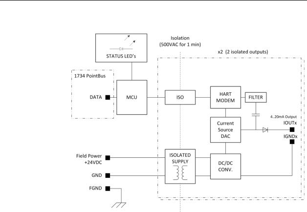
1.6.2 Module Operation
The 1734sc-OE2CIH has two, single-ended, 4-20 mA and 0-20 mA isolated current output modules. HART capability is available only on the 4-20 mA range. The module is fault protected to ±24 VDC. The module also contains a 16-bit DAC. The 1734scOE2CIH has HART Primary Master capability. A dedicated HART modem is used for each channel for maximum throughput. When HART functionality is enabled on a channel, the module discovers and establishes communication with HART revision 5 and greater devices. Once communication has been established, the module automatically gathers HART PV, SV, TV, and FV data, and monitors device status. The modules provide a communication bridge via Common Industrial Protocol (CIP) messaging to HART devices for Asset Management Software and Ladder Programs.
User’s Manual Pub. 0300272-01 Rev. A.0
1-6 Chapter 1: Module Overview
See the block diagram below.
User’s Manual Pub. 0300272-01 Rev. A.0
Chapter 2
Installation and Wiring
This chapter will cover:
Compliance to European Union directives
Power requirements
General considerations
Mounting
Field wiring connections
Section 2.1 Compliance to European Union Directives
This product is approved for installation within the European Union and EEA regions. It has been designed and tested to meet the following directives.
2.1.1 EMC Directive
The 1734sc-OE2CIH module is tested to meet Council Directive 89/336/EEC Electromagnetic Compatibility (EMC) and the following standards, in whole or in part, documented in a technical construction file:
IEC 61000-6-4:2007 Electromagnetic compatibility (EMC)–Part 6-4: Generic standards–Emission standard for industrial environments
IEC 61000-6-2:2005 Electromagnetic compatibility (EMC)–Part 6-2: Generic standards–Immunity for industrial environments
This product is intended for use in an industrial environment.
2.1.2 Low Voltage Directive
This product is tested to meet Council Directive 73/23/EEC Low Voltage by applying the safety requirements of EN 61131-2 Programmable Controllers Part 2–Equipment Requirements and Tests. For specific information required by EN61131-2, see the appropriate sections in this publication as well as the following Allen-Bradley publications:
Industrial Automation Wiring and Grounding Guidelines for Noise Immunity publication 1770-4.1
Automation Systems Catalog publication B113

2-2 |
Chapter 2: Installation and Wiring |
|
|
Section 2.2 Power Requirements
The module receives power through the bus interface from the +5 VDC/+24 VDC system power supply. The maximum current drawn by the module is shown in the table below.
5 VDC 24 VDC Field Supply
55 mA
175 mA at 12 VDC (2.1 VA max)
77 mA at 24 VDC is typical (1.85 VA)
WARNING |
Output may not remain steady or may drop out if the module is set |
|
up for maximum power draw, and the input supply voltage is down |
||
|
||
|
close to its low range (around 10 volts for the supply range). When |
|
|
the module is also operating at, or close to, its maximum operating |
|
|
temperature of 55 degrees Centigrade, the output reductions or |
|
|
dropouts may increase. |
|
|
Maximum specified load on each channel is 750 ohms. Maximum |
|
|
specified output current is 20 milliamperes. |
|
|
For Power Supply Voltages less than 12 V limit the output load to |
|
|
400 ohms if using 20 mA output current or limit the output current |
|
|
to 16 mA into the maximum load of 750 ohms. |
|
|
|
Section 2.3 General Considerations
1734 I/O is suitable for use in an industrial environment when installed in accordance with these instructions. Specifically, this equipment is intended for use in clean, dry environments Pollution degree 21 and to circuits not exceeding Over Voltage Category II2(IEC 60664-1)3.
2.3.1 Hazardous Location Considerations
This equipment is suitable for use in Class I, Division 2, Groups A, B, C, D or nonhazardous locations only. The following WARNING statement applies to use in hazardous locations.
1Pollution Degree 2 is an environment wherenormallyonly non-conductive pollution occurs except that occasionally a temporary conductivity caused by condensation shall be expected.
2Over Voltage Category II is the load level section of the electrical distribution system. At this level transient voltages are controlled and do not exceed the impulse voltage capability of the product’s insulation.
3Pollution Degree 2 and Over Voltage Category II are International Electrotechnical Commission (IEC) designations.
User’s Manual Pub. 0300272-01 Rev. A.0
Chapter 2: Installation and Wiring |
2-3 |
|
|
WARNING Explosion Hazard
Substitution of components may impair suitability for Class I Division 2.
Wear an approved wrist-strap grounding device.
Do not touch the backplane connector or connector pins.
Do not touch circuit components inside the module.
If available, use a static-safe work station.
When not in use, keep the module in its static-shield box.
2.3.2Prevent Electrostatic Discharge
WARNING Hazard of damage to equipment.
Electrostatic discharge can damage integrated circuits or semiconductors if you touch analog I/O module bus connector pins or the terminal block on the input module. Follow these guidelines when you handle the module:
Touch a grounded object to discharge static potential.
Wear an approved wrist-strap grounding device.
Do not touch the bus connector or connector pins.
Do not touch circuit components inside the module.
If available, use a static-safe work station.
When not in use, keep the module in its static-shield box.
2.3.3Remove Power
WARNING Hazard of injury to personnel or damage to equipment.
When you remove or insert a module with power applied, an electrical arc may occur. An electrical arc can cause personal injury or property damage by:
Causing an explosion in a hazardous environment.
Sending an erroneous signal to your system’s field devices, causing unintended machine motion.
Electrical arcing causes excessive wear to contacts on both the module and its mating connection, and may lead to premature equipment failure.
Before removing or inserting this module, remove power.
2.3.4 Selecting a Location
Reducing Noise
Most applications require installation in an industrial enclosure to reduce the effects of electrical interference. Analog outputs are highly susceptible to electrical noise. Electrical noise coupled to the analog outputs will reduce the performance (accuracy) of the module. Group your modules to minimize adverse effects from radiated electrical noise and heat. Consider the following conditions when selecting a location for the
User’s Manual Pub. 0300272-01 Rev. A.0

2-4 |
Chapter 2: Installation and Wiring |
|
|
analog module. Position the module:
Away from sources of electrical noise such as hard-contact switches, relays, and AC motor drives
Away from modules which generate significant radiated heat. Refer to the module’s heat dissipation specification.
In addition, route shielded, twisted-pair analog input wiring away from any high-voltage I/O wiring.
Section 2.4
Mounting
2.4.1 Before You Begin
Note that this product can be used with the following:
1734 ControlNet and EtherNet/IP adapters ONLY using RSLogix 5000 software version 11 or later
Refer to the following figures to familiarize yourself with major parts of the module, noting that the wiring base assembly is one of the following:
1734-TB or 1734-TBS POINT I/O two-piece terminal base, which includes the 1734-RTB removable terminal block and 1734-MB mounting base
1734-TOP or 1734-TOPS POINT I/O one-piece terminal base
User’s Manual Pub. 0300272-01 Rev. A.0

Chapter 2: Installation and Wiring |
2-5 |
|
|
2.4.2 Install Mounting Base
WARNING Hazard of damage to module on power up.
Debris that falls into the module could cause damage when power is applied to the module.
During panel or DIN rail mounting of all devices, be sure that all debris (such as metal chips or wire strands) is kept from falling into the module.
To install the mounting base on the DIN rail, proceed as follows:
1.Position the mounting base vertically above the installed units (adapter power supply or existing module).
2.Slide the mounting base down allowing the interlocking side pieces to engage the adjacent module or adapter.
3.Press firmly to seat the mounting base on the DIN rail. The mounting base will snap into place.
4.To remove the mounting base from the DIN rail, remove the module, and use a small-bladed screwdriver to rotate the base locking screw to a vertical position. This releases the locking mechanism. Then lift straight up to remove.
User’s Manual Pub. 0300272-01 Rev. A.0

2-6 |
Chapter 2: Installation and Wiring |
|
|
2.4.3 Install the Output Module
The module can be installed before, or after, base installation. Make sure that the mounting base is correctly keyed before installing the module into the mounting base. In addition, make sure the mounting base locking screw is positioned horizontal referenced to the base.
User’s Manual Pub. 0300272-01 Rev. A.0
Chapter 2: Installation and Wiring |
2-7 |
|
|
1.Using a bladed screwdriver, rotate the key switch on the mounting base clockwise until the number required for the type of module being installed aligns with the notch in the base.
2.Make certain the DIN rail locking screw is in the horizontal position. (You cannot insert the module if the locking mechanism is unlocked.)
3.Insert the module straight down into the mounting base and press to secure. The module will lock into place.
2.4.4 Install the Removable Terminal Block (RTB)
A removable terminal block is supplied with your wiring base assembly. To remove the terminal block, pull up on the RTB handle. This allows the mounting base to be removed and replaced as necessary without removing any of the wiring. To reinsert the removable terminal block, proceed as follows:
1.Insert the end opposite the handle into the base unit. This end has a curved section that engages with the wiring base.
2.Rotate the terminal block into the wiring base until it locks itself in place.
3.If an I/O module is installed, snap the RTB handle into place on the module.
2.4.5 Remove a Mounting Base
To remove a mounting base, you must remove any installed module, and the module installed in the base to the right. Remove the removable terminal block (if wired):
1.Unlatch the RTB handle on the I/O module.
2.Pull on the RTB handle to remove the removable terminal block.
3.Press on the module lock on the top of the module.
4.Pull on the I/O module to remove from the base.
5.Repeat steps 1, 2, 3, and 4 for the module to the right.
6.Use a small bladed screwdriver to rotate the orange base locking screw to a vertical position.
7.To release the locking mechanism, lift straight up to remove.
2.4.6 Install a 1734-TOPS Base
1.Position the base vertically above the installed units, such as an adapter, power supply, or existing module.
2.Slide the base down, allowing the interlocking side pieces to engage the adjacent installed unit.
3.Press firmly to seat the base on the DIN rail until the base snaps into place.
4.Verify that the DIN-rail locking screw is in a horizontal, locked position before inserting an I/O module.
2.4.7 Remove a 1734-TOPS Base
To remove a wiring base from the DIN rail, you must remove the module installed to the right of the base:
1.Squeeze the module locking mechanism of the module to the right of the base, pulling up to remove the module.
2.Turn the orange locking screw to a vertical position to unlock the base from the DIN rail.
3.Slide the base up to release it from its mating units.
User’s Manual Pub. 0300272-01 Rev. A.0

2-8 |
Chapter 2: Installation and Wiring |
|
|
Section 2.5
Field Wiring
Connections
Consider the following when wiring your system:
General
Power and input wiring must be in accordance with Class 1, Division 2 wiring methods, Article 501-4(b) of the National Electric Code, NFPA 70, and in accordance with the authority having jurisdiction.
Use Belden™ 8761 or equivalent, shielded wire.
To ensure optimum accuracy, limit overall cable impedance by keeping a cable as short as possible. Locate the module as close to input devices as the application permits.
Digital and analog power must be supplied by an Isolated Secondary Limited Energy Low Voltage source.
Outputs
The module provides loop power for analog outputs.
Grounding
NOTE |
Use supply wires suitable for 10°C above surrounding ambient |
|
temperature. |
||
|
This product is intended to be mounted to a well-grounded mounting surface such as a metal panel. Additional grounding connections from the module’s mounting tabs or DIN rail (if used) are not required unless the mounting surface cannot be grounded.
Under normal conditions, the drain wire (shield) should be connected to the metal mounting panel (earth ground). Keep shield connection to earth ground as short as possible.
Ground the shield drain wire at one end only. The typical location is as follows:
-For grounded thermocouples or millivolt sensors, this is at the sensor end.
-For insulated/ungrounded thermocouples, this is at the module end. Contact your sensor manufacturer for additional details.
Refer to Industrial Automation Wiring and Grounding Guidelines, Allen-
Bradley publication 1770-4.1, for additional information.
User’s Manual Pub. 0300272-01 Rev. A.0

Chapter 2: Installation and Wiring |
2-9 |
|
|
Noise Prevention
Route field wiring away from any other wiring and as far as possible from sources of electrical noise, such as motors, transformers, contactors, and AC devices. As a general rule allow at least 15.2 cm (6 in.) of separation for every 120 V of power.
Routing field wiring in a grounded conduit can reduce electrical noise.
If field wiring must cross AC or power cables, ensure that they cross at right angles.
If noise persists for a device, try grounding the opposite end of the cable shield or ground both ends of the shield.
2.5.1 Wiring Diagram
Refer to the following wiring diagrams for field wiring connections.
Table 2-1 (2 Channel Terminal Block Pinout)
|
RTB |
Usage |
RTB |
Usage |
|
Pin# |
|
Pin# |
|
|
|
|
|
|
|
0 |
Isolated 0ut0+ |
1 |
Isolated 0ut1+ |
|
|
|
|
|
|
2 |
Isolated Out0- |
3 |
Isolated Out1- |
|
|
|
|
|
|
4 |
Unused |
5 |
Unused |
|
|
|
|
|
|
6 |
Chassis GND |
7 |
Chassis GND |
|
|
(FGND) |
|
(FGND) |
|
|
|
|
|
|
|
|
|
|
Figure 2-1 (OE2CIH Wiring Diagram) |
|
|||
User’s Manual Pub. 0300272-01 Rev. A.0
Loading...