


Owner’s Guide 0300191-04 Rev.A
CONTROLLOGIX™
UNIVERSAL ANALOG INPUT MODULE
Catalog Number: 1756sc-IF8u
Important Notes |
1. Please read all the information in this owner’s guide before installing |
|
the product. |
|
2. The information in this owner's guide applies to hardware version A |
|
and firmware version 2.0 or later. |
|
3. This guide assumes that the reader has a full working knowledge of the |
|
relevant processor. |
|
Notice |
|
The products and services described in this owner's guide are useful in a |
|
wide variety of applications. Therefore, the user and others responsible |
|
for applying the products and services described herein are responsible |
|
for determining their acceptability for each application. While efforts |
|
have been made to provide accurate information within this owner's |
|
guide, Spectrum Controls assumes no responsibility for the accuracy, |
|
completeness, or usefulness of the information herein. |
|
Under no circumstances will Spectrum Controls be responsible or liable |
|
for any damages or losses, including indirect or consequential damages |
|
or losses, arising out of either the use of any information within this |
|
owner's guide or the use of any product or service referenced herein. |
|
No patent liability is assumed by Spectrum Controls with respect to the |
|
use of any of the information, products, circuits, programming, or |
|
services referenced herein. |
|
The information in this owner's guide is subject to change without notice. |
|
LimitedWarranty |
|
Spectrum Controls warrants that its products are free from defects in |
|
material and workmanship under normal use and service, as described in |
|
Spectrum Controls literature covering this product, for a period of 1 year. |
|
The obligations of Spectrum Controls under this warranty are limited to |
|
replacing or repairing, at its option, at its factory or facility, any product |
|
which shall, in the applicable period after shipment, be returned to the |
|
Spectrum Controls facility, transportation charges prepaid, and which |
|
after examination is determined, to the satisfaction of Spectrum Controls, |
|
to be thus defective. |
|
This warranty shall not apply to any such equipment which shall have |
|
been repaired or altered except by Spectrum Controls or which shall |
|
have been subject to misuse, neglect, or accident. In no case shall the |
|
liability of Spectrum Controls exceed the purchase price. The |
|
aforementioned provisions do not extend the original warranty period of |
|
any product which has either been repaired or replaced by Spectrum |
|
Controls. |

Who Should Use
This Guide
What This Guide
Covers
Related Allen-
Bradley Documents
Preface
Read this preface to familiarize yourself with the rest of the owner’s guide. This preface covers:
•who should use this guide
•what this guide covers
•related Allen-Bradley documents
•terms & abbreviations you should know
Use this guide if you design, install, program, or maintain a control system that uses Allen-Bradley ControlLogix Controllers.
You should have a basic understanding of ControlLogix products. You should also understand electronic process control and the ladder program instructions required to generate the electronic signals that control your application. If you do not, contact your local Allen-Bradley representative for the proper training before using these products.
This guide covers the 1756sc-IF8u universal analog input module. It contains the information you need to install, wire, use, and maintain these modules. It also provides diagnostic and troubleshooting help should the need arise.
Table A lists several Allen-Bradley documents that may help you as you use these products.
Table A. Related Allen-Bradley documents
Allen-Bradley Doc. No. |
Title |
Publication Number |
|
|
|
||
1756-PA72, ControlLogix Power Supply Installation |
|
||
-PB72 |
Instructions |
|
1756-5.1 |
1756-A4, |
ControlLogix Chassis Installation Instructions 1756-5.2 |
||
-A7, -A10, |
|
|
|
-A13, -A17 |
|
|
|

vi |
ControlLogix™ UniversalAnalogInputModules |
|
|
Terms &
Abbreviations You
Should Know
1756 Series ControlLogix Module Installation Instructions |
|
(Each module has separate document for installation) |
1756-5.5, |
|
-5.42 |
1756-L1, Logix5550 Controller User Manual |
1756-6.5.12 |
-L1M1, -L1M2 |
|
1756-DHRIO ControlLogix Data Highway Plus |
|
Communication Interface Module User Manual |
1756-6.5.2 |
1756-ENET ControlLogix Ethernet Communication Interface |
|
Module User Manual |
1756-6.5.1 |
To obtain a copy of any of the Allen-Bradley documents listed, contact your local Allen-Bradley office or distributor.
You should understand the following terms and abbreviations before using this guide.
A/D - Refers to analog-to-digital conversion. The conversion produces a digital value whose magnitude is proportional to the instantaneous magnitude of an analog input signal.
Attenuation – The reduction in magnitude of a signal as it passes through a system. The opposite of gain.
Channel – Refers to one of eight, small-signal analog input interfaces to the module’s terminal block. Each channel is configured for connection to a input device, and has its own configuration and status words.
Chassis – See rack.
CJC - (Cold Junction Compensation) The means by which the module compensates for the offset voltage error introduced by the temperature at the junction between the thermocouple lead wire and the input terminal block (the cold junction).
Common mode rejection ratio (CMRR) - The ratio of a device’s differential voltage gain to common mode voltage gain. Expressed in dB, CMRR is a comparative measure of a device’s ability to reject interference caused by a voltage common to its terminal relative to ground.
Common mode voltage – The voltage difference between the negative terminal and analog common during normal differential operation.
Preface |
vii |
Cut-off frequency - The frequency at which the input signal is attenuated 3 dB by the digital filter. Frequency components of the input signal that are below the cut-off frequency are passed with under 3 dB of attenuation for low-pass filters.
dB (decibel) – A logarithmic measure of the ratio of two signal levels.
Digital filter - A low-pass mathmatic single order filter applied to the A/D signal. The digital filter provides high-frequency noise rejection.
Effective resolution – The number of bits in the channel data word that do not vary due to noise.
Local System - A control system with I/O chassis within several feet of the processor.
LSB (least significant bit) – The bit that represents the smallest value within a string of bits.
Mulitplexer – A switching system that allows several input signals to share a common A/D converter.
Normal mode rejection (differential mode rejection) – A logarithmic measure, in dB, of a device’s ability to reject noise signals between or among circuit signal conductors, but not between the equipment grounding conductor or signal reference structure and the signal conductors.
Module update time – See channel update time.
Remote system - A control system where the chassis can be located several thousand feet from the processor chassis. Chassis communication is via the 1756-DHRIO and 1756-ENET Adapter.
Resolution – The smallest detectable change in a measurement, typically expressed in engineering units (e.g. 0.15 °C) or as a number of bits. For example, a 12-bit system has 4096 possible output states. It can therefore measure 1 part in 4096. See also effective resolution.
RTD (Resistance Temperature Detector) - A temperature sensing element with 2, 3, 4, lead wires. It uses the basic characteristics that electrical resistance of metals increases with temperature. When a small current is applied to the RTD, it creates a voltage that varies with temperature. This voltage is processed and converted by the RTD module into a temperature value.
Sampling time - The time required by the A/D converter to sample an input channel.
viii |
ControlLogix™ UniversalAnalogInputModules |
|
|
Step response time – The time required for the A/D signal to reach 95% of its expected, final value, given a full-scale step change in the output data word.
Tags - Identifiers for configuration, data, and status information found withing the module. Tags allow the user to modify specific module attributes and view data and status.
Update time – The time for the module to sample and convert a channel input signal and make the resulting value available to the ControlLogix processor.
Table of Contents
Preface v
Module Overview 1
Installing And Wiring
Your Module |
9 |
Operation Within the
ControlLogix
System 23
Programming Your
Module 29
Who Should Use This Guide ................................................................................... |
v |
What This Guide Covers .......................................................................................... |
v |
Related Allen-Bradley Documents ........................................................................... |
v |
Table A. Related Allen-Bradley documents ............................................................. |
v |
Terms & Abbreviations You Should Know ............................................................. |
vi |
General Description .................................................................................................. |
1 |
Detailed Specifications ............................................................................................. |
2 |
Hardware Features .................................................................................................... |
3 |
Diagnostic LEDs ....................................................................................................... |
4 |
System Overview ...................................................................................................... |
4 |
System Operation ..................................................................................................... |
5 |
Module Operation .................................................................................................... |
5 |
Compatibility with Thermocouple, Current, and Millivolt Devices & Cables ......... |
6 |
Electrostatic Damage ................................................................................................ |
9 |
Power Requirements ............................................................................................... |
10 |
Table 2.1 Maximum current drawn by the module ................................................. |
10 |
Module Installation and Removal .......................................................................... |
10 |
Figure 2.1 Module insertion into a rack ................................................................ |
13 |
Figure 2.2 Terminal block diagram with keying ..................................................... |
14 |
Wiring Your Module .............................................................................................. |
14 |
Preparing and Wiring the Cables ........................................................................... |
15 |
Terminal Block Layout ............................................................................................ |
16 |
Wiring Voltage/Current Inputs the IF8u Module ................................................... |
17 |
Wiring RTD or Resistance Sensors to the IF8u Module ....................................... |
18 |
Wiring Thermocouples to the IF8u Module .......................................................... |
20 |
Ownership and Connections .................................................................................. |
23 |
Using RSNetWorx and RSLogix 5000 ..................................................................... |
23 |
Direct Connections ................................................................................................. |
24 |
Module Operation .................................................................................................. |
24 |
Modules in a Local Chassis ................................................................................... |
25 |
Requested Packet Interval (RPI) ............................................................................ |
25 |
Modules in a Remote Chassis ................................................................................ |
26 |
Listen-Only Mode .................................................................................................. |
27 |
Multiple Owners of Input Modules ....................................................................... |
27 |
Configuration Changes in an Input Module with Multiple Owners ...................... |
28 |
Module Installation ................................................................................................ |
29 |
Adding Your Module to a Project .......................................................................... |
29 |
Configuring module attributes: Configuration Tags .............................................. |
34 |
x |
ControlLogix™ UniversalAnalogInputModules |
|
|
Configuration, Data, and Status Tags
37
Send Configuration Data to the Module ................................................................ |
37 |
Configuration Tags ................................................................................................. |
38 |
Global Module Settings .......................................................................................... |
38 |
Channel Specific Settings ....................................................................................... |
43 |
Input Tags .............................................................................................................. |
50 |
Fault and Status Reporting Tags ........................................................................... |
50 |
Module Data Tags .................................................................................................. |
53 |
Programming
Examples 55
Troubleshooting 61
Maintaining Your Module
And Ensuring Safety 65
Module
Specifications
69
Thermocouple
Descriptions 75
Initial Programming ................................................................................................. |
55 |
Figure 5.1 Sample Ladder Logic ............................................................................ |
56 |
Using Module Indicators to Troubleshoot ............................................................ |
61 |
Using RSLogix 5000 to Troubleshoot Your Module .............................................. |
62 |
Module Configuration Errors ................................................................................. |
64 |
Preventive Maintenance ........................................................................................ |
65 |
Safety Considerations ............................................................................................ |
65 |
Electrical Specifications .......................................................................................... |
69 |
Physical Specifications .......................................................................................... |
70 |
Environmental Specifications ................................................................................. |
70 |
Input Specifications ............................................................................................... |
70 |
J Type Thermocouples ........................................................................................... |
75 |
K Type Thermocouples .......................................................................................... |
77 |
T Type Thermocouples .......................................................................................... |
79 |
E Type Thermocouples .......................................................................................... |
81 |
R Type Thermocouples .......................................................................................... |
83 |
S Type Thermocouples .......................................................................................... |
84 |
B Type Thermocouples .......................................................................................... |
86 |
N Type Thermocouples .......................................................................................... |
87 |
References .............................................................................................................. |
90 |
Using Grounded
Junction,
Ungrounded
Junction, and
Exposed Junction
Thermocouples 97
Programming Your
Module 101
TableofContents |
xi |
Thermocouple Types .............................................................................................. |
97 |
Grounded Junction ................................................................................................. |
98 |
Ungrounded (Insulated) Junction .......................................................................... |
98 |
Exposed Junction ................................................................................................... |
98 |
Isolation .................................................................................................................. |
98 |
Module Installation .............................................................................................. |
101 |
Adding Your Module to a Project ........................................................................ |
101 |
Declaration of Conformity .................................................................................... |
105 |
xii |
ControlLogix™ UniversalAnalogInputModules |
|
|
Chapter 1
|
Module Overview |
|
This chapter describes the universal analog input module and explains how |
|
the ControlLogix controller reads analog input data from the module. Read |
|
this chapter to familiarize yourself further with your universal analog input |
|
module. This chapter covers: |
|
• general description and hardware features |
|
• an overview of system and module operation |
General Description |
This module is designed exclusively for use in the Allen-Bradley |
|
ControlLogix 1756 I/O rack systems. The module stores digitally |
|
converted thermocouple, RTD, resistance, millivolt (mV), volt (V), |
|
milliamp (mA), and CJC temperature analog data in its image table for |
|
retrieval by all ControlLogix processors. |
|
Following is a list of features available on the IF8u module that allow their |
|
use in a wide variety of applications. |
|
· Removal and insertion under power (RIUP) - a system feature that |
|
allows you to remove and insert modules while chassis power is applied |
|
· Producer/consumer communications - an intelligent data exchange |
|
between modules and other system devices in which each module |
|
produces data without having been polled |
|
· Rolling timestamp of data - 15 bit module-specific rolling timestamp with |
|
millisecond resolution which indicates when data was sampled/applied. |
|
This timestamp may be used to calculate the interval between channel or |
|
updates |
|
· System timestamp of data - 64 bit system clock places a timestamp on |
|
the transfer of data between the module and its owner controller within |
|
the local chassis |
|
· IEEE 32 bit floating point format |
|
· On-Board Features, such as custom User Scaling, Process Alarms, Rate |
|
Alarms, Digital Filtering, and Under/Overrange Detection |
|
· Automatic Calibration - analog I/O modules may perform autocalibration |
|
on a channel-by-channel or module-wide basis to reduce drift inaccuracies |
|
due to module ambient temperature changes. |
|
· Class I/Division 2, UL, CSA, CE, and FM Agency Certification |

2 |
ControlLogix™ CounterModule |
|
|
Detailed
Specifications
Input Ranges
The following tables provide compatibility information on the supported thermocouple types and their associated temperature ranges, the supported RTD types and their associated temperature ranges, as well as the millivolt, volt, milliamp and resistance input types supported by the IF8u module. To determine the practical temperature range of your thermocouple, refer to the specifications in appendices A and B.
Table 1.1 Thermocouple Temperature Ranges
Type °CTemperatureRange
J-210°Cto1200°C
K-270°Cto1372°C
T |
-270°Cto400°C |
B |
300°Cto1820°C |
E |
-270°Cto1000°C |
R0°C to 1768°C
S0°Cto1768°C
N |
-210°Cto1300°C |
C |
0°C to 2315°C |
CJCSensor |
0°Cto90°C |
°FTemperatureRange
-346°Fto2192°F -454°Fto2502°F -454°Fto752°F 572°Fto3308°F -454°Fto1832°F 32°F to 3214°F 32°Fto3214°F -346°Fto2372°F 32°F to 4199°F 32°F to 194°F
Table 1.2 RTD Temperature Ranges
Type °C Temp Range
Platinum(385)
100Ohm |
-200°Cto+850°C |
200Ohm |
-200°Cto+850°C |
500Ohm |
-200°Cto+850°C |
1000Ohm |
-200°Cto+850°C |
Platinum(3916) |
|
100Ohm |
-200°Cto+630°C |
200Ohm |
-200°Cto+630°C |
500Ohm |
-200°Cto+630°C |
1000Ohm |
-200°Cto+630°C |
Copper(426) |
|
10Ohm |
-100°Cto+260°C |
Nickel(618) |
|
120Ohm |
-100°Cto+260°C |
200Ohm |
-100°Cto+260°C |
500Ohm |
-100°Cto+260°C |
1000Ohm |
-100°Cto+260°C |
Nickel(672) |
|
120Ohm |
-80°Cto+260°C |
Nickel/Iron(518) |
|
604Ohm |
-100°Cto+200°C |
°F Temp Range
-328°Fto+1562°F -328°Fto+1562°F -328°Fto+1562°F -328°Fto+1562°F
-328°Fto+1166°F -328°Fto+1166°F -328°Fto+1166°F -328°Fto+1166°F
-148°Fto+500°F
-148°Fto+500°F -148°Fto+500°F -148°Fto+500°F -148°Fto+500°F
-112°Fto+500°F
-148°Fto+392°F
ThedigitsinparenthisisfollowingtheRTDtyperepresentthetemperaturecoefficientofresistance(alpha,a), whichisdefinedastheresistancechangeperOhmper°°C.Forinstance,Platinum385referstoaplatinumRTD witha=0.00385Ohms/Ohm- °C,orsimply0.00385/°°C.
|
Chapter1:ModuleOverview |
3 |
|
Table 1.3 Millivolt Input Ranges |
|
|
|
|
|
StatedActual |
|
|
-50to+50mV(-75to+75mV) |
|
|
-150to+150mV(-175to+175mV) |
|
|
0to+5.0V(-0.5to+5.5V) |
|
|
1.0to+5.0V(0.5to+5.5V) |
|
|
0to10.0V(-0.5to10.0V) |
|
|
-10.0to+10.0V(-10.0to+10.0V) |
|
|
Table 1.4 Current Input Ranges |
|
|
|
|
|
4to20mA(-3.5to+21.5mA) |
|
|
0to20mA(0to+21.5mA) |
|
|
|
|
|
Table 1.5 Resistance Input Range |
|
|
|
|
|
0to250Ohms |
|
|
0to500Ohms |
|
|
0to1000Ohms |
|
|
0to2000Ohms |
|
|
0to3000Ohms |
|
|
0to4000Ohms |
|
|
All eight input channels are individually configurable for RTD, resistance, |
|
|
thermocouple, millivolt, volt, or milliamp input types. Each input channel |
|
|
provides wire-off input, over-range, and under-range detection and |
|
|
indication, when enabled. |
|
Hardware Features |
The module fits into any single slot for I/O modules in a ControlLogix |
|
|
modular system. The module has a unique generic profile which may be |
|
|
configured using your RSLogix 5000 programming software. |
|
The module utilizes one removable terminal block, that provides connections for the eight input channels. There are two cold-junction compensation (CJC) sensors that compensate for the cold junction at ambient temperature rather than at freezing (0°C). There are eight current sources for supplying the RTD or resistance sensors. The module is configured through RSLogix 5000 software, defining RTD, resistance, current or voltage input paths.
4 |
ControlLogix™ CounterModule |
|
|
|
Table 1.6 Hardware Features |
|
|
|
HardwareFunction |
|
OKLEDDisplayscommunicationandfaultstatusofthemodule |
|
CalLEDDisplaysafaultcondition |
|
SideLabel(Nameplate)Providesmoduleinformation |
|
RemovableTerminalBlockProvideselectricalconnectiontoinputdevices |
|
DoorLabelPermitseasyterminalidentification |
|
SelfLockingTabsSecuremoduleinchassisslot |
|
TerminalBlockSwitchLockstheRTBtothemodule. |
Diagnostic LEDs |
The module contains diagnostic LEDs that help you identify the source of |
|
problems that may occur during power-up or during normal operation. |
|
Power-up and diagnostics are explained in Chapter 7, Testing Your |
|
Module. |
System Overview |
The module communicates with the ControlLogix processor and receives |
|
+5 Vdc and +24 Vdc power from the system power supply through the |
|
parallel backplane interface. You may install as many universal modules in |
|
the system as the power supply can support. Channels (0 through 7) can |
|
receive input signals from RTDs, resistance sources, thermocouples, |
|
millivolt, volt, or milliamp devices. When configured for thermocouple input |
|
types, the module converts analog input voltages into cold-junction |
|
compensated and linearized, digital temperature readings. The module uses |
|
the National Institute of Standards and Technology (NIST) linearization |
|
tables based on ITS-90 for thermocouple linearization. |
|
When configured for RTD input types, the module converts the analog |
|
input voltages into digital temperature readings, based on the alpha type, |
|
wire type, and ohms specified. The standards used are the JIS C 1604- |
|
1997 for the Pt 385 RTD types, the JIS C 1604-1989 for the Pt 3916 RTD |
|
types, SAMA RC21-4-1966 for the 10. Cu 426 RTD, DIN 43760 Sept. |
|
1987 for the 120. Ni 618 RTD, and MINCO Application Aid #18 May |
|
1990 for the 120. Ni 672 RTD.When configured for millivolt, volt, milliamp, |
|
or resistance analog inputs, the module converts the analog values directly |
|
into floating point values. For those input types, the module assumes that |
|
the input signal is linear prior to input into the module. |

System Operation
Module Operation
Chapter1:ModuleOverview |
5 |
Table 1.6 Hardware Features
HardwareFunction
OKLEDDisplayscommunicationandfaultstatusofthemodule
CalLEDDisplaysafaultcondition
SideLabel(Nameplate)Providesmoduleinformation
RemovableTerminalBlockProvideselectricalconnectiontoinputdevices
DoorLabelPermitseasyterminalidentification
SelfLockingTabsSecuremoduleinchassisslot
TerminalBlockSwitchLockstheRTBtothemodule.
At power-up, the module checks internal circuits, memory, and basic functions. During this time the Cal LED remains on. If the module does not find any faults, it turns off the Cal LED. After completing power-up checks, the module wait for a connection to an owner controller then valid channel configuration data from your ladder logic program. After channel configuration data is transferred, and one or more channels are enabled, the module continuously converts the inputs to floating point data for use in your ladder program.
Each time the module reads an input channel, the module tests that data for a fault, i.e. over-range, or under-range condition. If it detects an overrange or under-range condition, the module sets a unique bit in the status tags.
The module’s input circuitry consists of eight differential analog inputs, multiplexed into an A/D converter. The A/D converter reads the analog input signals and converts them to floating point values.. The input circuitry also continuously samples the CJC sensors, if not disabled and compensates for temperature changes for thermocouples at the cold junction (terminal block). The sensors must be Spectrum Controls supplied temperature sensors. The module will not accept other CJC sensor inputs, and thermocouple inputs will not function properly if incorrect CJC sensors are used. Two CJC sensors are shipped with each module.

6 |
ControlLogix™ CounterModule |
|
|
Compatibility with Thermocouple, Current, and Millivolt Devices & Cables
The module is compatible with the following standard types of thermocouples: B, E, J, K, N, R, S, T and C and extension wire. Refer to appendices B and C for details. The module is also compatible with a variety of voltage and current devices with an output of ±50, ±150 mV, 0- 5V, 1-5V, 0-10V, ±10V, 0-20mA, and 4-20mA. To minimize interference from radiated electrical noise, we recommend twisted-pair and highly shielded cables such as the following:
Table 1.7 Recommendations to minimize interference from radiated electrical noise
ForThisTypeofDeviceWeRecommendThisCable(orequivalent)
ThermocoupleTypeJEILCorp.J20-5-502
ThermocoupleTypeKEILCorp.K20-5-510
ThermocoupleTypeTEILCorp.T20-5-502
OtherThermocoupleTypesconsultwithEILCorporothermanufacturersmV,V,mAdevicesBelden8761, shielded,twisted-pairCompatibilitywithRTDandResistancedevicesandcables
The module is compatible 100. Platinum 385, 200. Platinum 385, 500. Platinum 385, 1000. Platinum 385, 100. Platinum 3916, 200. Platinum 3916, 500. Platinum 3916, 1000. Platinum 3916, 10. Copper 426, 120. Nickel 618 and 120. Nickel 672 RTD types and resistance inputs, and 3 possible wire types (2 wire, 3 wire, or 4 wire). Each RTD input individually supports three input pins on the terminal block: one excitation current source (EXC+), one sense positive (IN+) and one sense negative (IN-). Only those pins are connected that are required by the selected RTD or resistance wire type. For 2, 3, or 4 wire configurations, the module can support a maximum combined cable length associated with an overall cable impedance of 25 ohms or less without exceeding its input limitations. The accuracy specifications provided herein do not include errors associated with unbalanced cable impedance.
Since the operating principle of the RTD and resistance inputs is based on the measurement of resistance, take special care in selecting your input cable. For 2-wire or 3-wire configuration, select a cable that has a consistent impedance throughout its entire length. For 2-wire configurations, we recommend that you use Belden #9501 (or equivalent). For 3-wire configurations, we recommend that you use Belden #9533 (or equivalent) for short installation runs (less than 100 feet) or use Belden #83503 (or equivalent) for longer runs (greater than 100 feet) and in high humidity environments.

Chapter1:ModuleOverview |
7 |
Table 1.8 Cable Specifications
Description |
Belden#9501 |
Belden#9533 |
Belden#83503 |
For |
2-wireRTDsand |
3-wireRTDsand |
3-wireRTDsand |
|
potentiometers. |
potentiometers. |
Shortpotentiometers. |
When used? Long runs less than 100 feet runs greater than 100
8 |
ControlLogix™ CounterModule |
|
|
Chapter 2
Installing And Wiring Your Module
Read this chapter to install and wire your module. This chapter covers:
•avoiding electrostatic damage
•determining power requirements
•installing the module
•wiring signal cables to the module’s terminal block
Electrostatic
Damage Electrostatic discharge can damage semiconductor devices inside this module if you touch backplane connector pins. Guard against electrostatic damage by observing the following precautions:
CAUTION
!ELECTROSTATICALLY SENSITIVE COMPONENTS
•Before handling the module, touch a grounded object to rid yourself of electrostatic charge.
•When handling the module, wear an approved wrist strap grounding device.
•Handle the module from the front, away from the
backplane connector. Do not touch backplane connector pins.
• Keep the module in its static-shield container when not in use or during shipment.
Failure to observe these precautions can degrade the module’s performance or cause permanent damage.

10 |
ControlLogix™ UniversalAnalogInputModule |
|
|
Power
Requirements
Module Installation
and Removal
The module receives its power through the ControlLogix chassis backplane from the fixed or modular +5 VDC and +24 VDC chassis power supply. The maximum current drawn by the module is shown in the table below.
Table 2.1. Maximum current drawn by the module
5VDC Amps |
24VDC Amps |
|
|
0.230 |
0.075 |
|
|
Using your module in the ControlLogix System
Place your module in any slot of a ControlLogix modular, or modular expansion chassis.
An analog I/O module translates an analog signal into, or from, a corresponding digital representation which controllers can easily operate on for control purposes.
A ControlLogix I/O module mounts in a ControlLogix chassis and uses a Removable Terminal Block (RTB) to connect all field-side wiring.
Before you install and use your module you should have already:
·installed and grounded a 1756 chassis and power supply.
·ordered and received an RTB for your application.
Important: RTBs are not included with your module purchase.
Specify Allen Bradley Part Number:
1756-TBCH - 36 position screw terminals
1756-TBS6H - 36 position press terminals
When installing the module in a chassis, it is not necessary to remove the terminal blocks from the module. However, if the terminal blocks are removed, use the write-on label located on the side of the terminal blocks to identify the module location and type.
Chapter2:InstallingAndWiringYourModule |
11 |
Preventing Electrostatic Discharge
This module is sensitive to electrostatic discharge.
ATTENTION: Electrostatic discharge can damage integrated
!circuits or semiconductors if you touch backplane connector pins. Follow these guidelines when you handle the module:
·Touch a grounded object to discharge static potential
·Wear an approved wrist-strap grounding device
·Do not touch the backplane connector or connector pins
·Do not touch circuit components inside the module
·If available, use a static-safe work station
·When not in use, keep the module in its static-shield box
Removal and Insertion Under Power
These modules are designed to be installed or removed while chassis power is applied.
ATTENTION: When you insert or remove a module while
!electrical arc can cause personal injury or property damage by:
·sending an erroneous signal to your system’s field devices causing unintended machine motion or loss of process control.
·causing an explosion in a hazardous environment.backplane power is applied, an electrical arc may occur. An
Repeated electrical arcing causes excessive wear to contacts on both the module and its mating connectors. Worn contacts may create electrical resistance that can affect module operation.
Compliance to European Union Directives
If this product bears the CE marking, it is approved for installation within the European Union and EEA regions. It has been designed and tested to meet the following directives.
EMC Directive
This product is tested to meet Council Directive 89/336/EEC Electromagnetic Compatibility (EMC) and the following standards, in whole or in part, documented in a technical construction file:

12 |
ControlLogix™ UniversalAnalogInputModule |
|
|
EN 61010-1 and EN 61131-2, EN61000-6-2:2001, EN61000-6-4:2001
EN61010-1:2001
This product is intended for use in an industrial environment.
Low Voltage Directive
This product is tested to meet Council Directive 73/23/EEC Low Voltage, by applying the safety requirements of EN 61131-2 Programmable Controllers, Part 2 - Equipment Requirements and Tests.
For specific information required by , EN61131-2:1994 + A11:1996 + A12:2000, see the appropriate sections in this publication, as well as the followingAllen-Bradley publications:
·Industrial Automation Wiring and Grounding Guidelines For Noise Immunity, publication 1770-4.1
·Automation Systems Catalog, publication B111
This equipment is classified as open equipment and must be installed (mounted) in an enclosure during operation as a means of providing safety protection.
CAUTION
!POSSIBLE EQUIPMENT OPERATION
ATTENTION: The module is designed to support Removal and Insertion Under Power (RIUP). However, when you remove or insert an RTB with field-side power applied, unintended machine motion or loss of process control can occur. Exercise extreme caution when using this feature.
WARNING
!The 1756sc-IF8U module is to be used only with the AllenBradley 1756 ControlLogix System.

Chapter2:InstallingAndWiringYourModule |
13 |
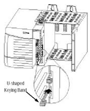
To insert your module into the rack, follow these steps:
1.Align the circuit board of your module with the card guides at the top and bottom of the chassis.
Figure 2.1. Module insertion into a rack
2.Key the RTB in positions that correspond to unkeyed module positions. Insert the wedge-shaped tab on the RTB with the rounded edge first. Push the tab onto the RTB until it stops.
Keying the Removable Terminal Block
Key the RTB to prevent inadvertently connecting the incorrect RTB to your module.
When the RTB mounts onto the module, keying positions will match up. For example, if you place a U-shaped keying band in position #4 on the module, you cannot place a wedge-shaped tab in #4 on the RTB or your RTB will not mount on the module.
We recommend that you use a unique keying pattern for each slot in the chassis.
1. Insert the U-shaped band with the longer side near the terminals. Push the band onto the module until it snaps into place.
14 |
ControlLogix™ UniversalAnalogInputModule |
|
|
Figure 2.2. Terminal block diagram with keying
Wiring Your Module |
Follow these guidelines to wire your input signal cables: |
•Power, input, and output (I/O) wiring must be in accordance with Class I, Division 2 wiring methods [Article 501-4(b) of the National Electrical Code, NFPA 70] and in accordance with the authority having jurisdiction.
•Peripheral equipment must be suitable for the location in which it is used.
•Route the field wiring away from any other wiring and as far as possible from sources of electrical noise, such as motors, transformers, contactors, and ac devices. As a general rule, allow at least 6 in. (about 15.2 cm) of separation for every 120 V of power.
•Routing the field wiring in a grounded conduit can reduce electrical noise further.
•If the field wiring must cross ac or power cables, ensure that they cross at right angles.
•To limit the pickup of electrical noise, keep thermocouple, RTD, millivolt, and milliamp signal wires as far from power and load lines as possible.
•For improved immunity to electrical noise, use Belden 8761 (shielded, twisted pair) or equivalent wire for millivolt sensors; or use shielded, twisted pair thermocouple extension lead wire specified by the thermocouple or RTD manufacturer. Using the incorrect type of thermocouple extension wire or not following the correct polarity may cause invalid readings.
•Ground the shield drain wire at only one end of the cable. The preferred location is at the shield connections at the ControlLogix chassis. (Refer to IEEE Std. 518, Section 6.4.2.7 or contact your sensor manufacturer for additional details.)
Chapter2:InstallingAndWiringYourModule |
15 |
•Keep all unshielded wires as short as possible.
•To limit overall cable impedance, keep input cables as short as possible. Locate your I/O chassis as near the RTD or thermocouple sensors as your application will permit.
•Tighten screw terminals with care. Excessive tightening can strip a screw. The RTB terminations can accommodate 2.1…0.25 mm2 (14…22 AWG) shielded wire and a torque of 0.5 N•m (4.4 lb•in.).
•Follow system grounding and wiring guidelines found in your ControlLogix Installation and Operation Manual.
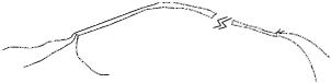
Preparing and Wiring the Cables
To prepare and connect cable leads and drain wires, follow these steps:
Signal Wires
Cable
Drain Wire
(At the module-end of the cable, extract the drain wire but remove the foil shield.)
(Remove foil shield and drain wire from sensor-end of the cable.)
Signal Wires
1.At each end of the cable, strip some casing to expose individual wires.
2.Trim signal wires to 5-inch lengths beyond the cable casing. Strip about 3/16 inch (4.76 mm) of insulation to expose the ends of the wires.
3.At the module-end of the cables (see figure above):
-extract the drain wire and signal wires
-remove the foil shield
-bundle the input cables with a cable strap
4.Connect pairs of drain wires together, Channels 0 and 1, Channels 2 and 3, Channels 4 and 5, Channels 6 and 7. Keep drain wires as short as possible.
5.Connect the drain wires to the grounding lug on the PLC chassis.
6.Connect the signal wires of each channel to the terminal block. Important: Only after verifying that your connections are correct for each channel, trim the lengths to keep them short. Avoid cutting leads too short.
7.At the source-end of cables from mV devices:
-remove the drain wire and foil shield
-apply shrink wrap as an option

16ControlLogix™ UniversalAnalogInputModule
-connect to mV devices keeping the leads short
Terminal Block
Layout
Important: If noise persists, try grounding the opposite end of the cable, instead (Ground one end only.)
The following figure shows the general terminal block layout. The input signal type will determine which pins are used.
Wiring Voltage/
Current Inputs the
IF8u Module
Chapter2:InstallingAndWiringYourModule |
17 |
Voltage inputs use the terminal block pins labelled IN+ and INCurrent inputs use the terminal block pins labelled IN+ and IN-
|
|
Voltage Inputs |
|
|
EXC+ |
|
|
|
IN+ |
Voltage + |
|
|
IN- |
Voltage - |
|
|
iRTN |
|
|
|
|
CABLE SHIELD |
|
|
|
Current Inputs |
|
ADD |
EXC+ |
|
|
IN+ |
Current + |
||
JUMPER |
|||
|
|
||
|
IN- |
Current - |
|
|
iRTN |
|
|
|
|
CABLE SHIELD |
18 |
ControlLogix™ UniversalAnalogInputModule |
|
|
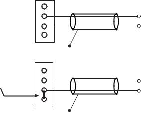
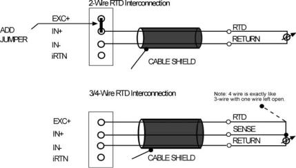
Wiring RTD or Resistance Sensors to the IF8u Module
The IF8u module supports two, three, and four wire RTDs or resistance inputs connected individually to the module as shown in the figure below.
These are:
*2-wire RTDs, which are composed of 2 RTD lead wires (EXC+ and INwith a jumper between EXC+ and IN+)
*3-wire RTDs, which are composed of a 2 Signal and 1 RTD return lead wires (EXC+ and IN+ with a the return RTD lead to IN-)
*4-wire RTDs, which are composed of 2 Signal and 2 RTD return lead wires (EXC+ and IN+ with a the return RTD lead to IN-) The fourth lead is not used so wiring is identical to 3 wires RTDs.
*2- wire Resistance, which is composed of 2 leads (EXC+ and INwith a jumper between EXC+ and IN+)
* 3- wire Resistance, which is composed of 3 leads (EXC+ IN+ and IN-) and the resistance lies between IN+ and IN-
In any RTD sensing system, it is important that the lead and sense wire resistances are matched as much as possible. The lead lengths, and their resulting impedances, must be matched and kept small to eliminate the introduction of connectivity errors. The 3/4-wire RTDs are the most accurate, with 2-wire RTDs being the most inaccurate. In 2-wire the lead resistance adds error to the resulting degree reading. With a 1.008mA current source, 1Ω of lead resistance adds 1.008µV, or 2.82°C error, with the 100Ω 385 alpha type. To gain an understanding of how lead resistance affects RTD readings, the µV/C for each RTD type is listed below.
 Loading...