


 Loading...
User’s Manual Pub. 0300274-01 Rev. A.0
Micro800™
BACnet Communication Module
Catalog Number: 2080sc-BAC
ii |
BACnet Communication Module |
|
|
User’s Manual Pub. 0300274-01 Rev. A.0
BACnet Communication Module |
iii |
|
|
Important Notes
1.Please read all the information in this owner’s guide before installing the product.
2.The information in this owner's guide applies to hardware Series A and firmware version 1.1 or later.
3.This guide assumes that the reader has a full working knowledge of the relevant processor.
Notice
The products and services described in this owner's guide are useful in a wide variety of applications. Therefore, the user and others responsible for applying the products and services described herein are responsible for determining their acceptability for each application. While efforts have been made to provide accurate information within this owner's guide, Spectrum Controls, Inc. assumes no responsibility for the accuracy, completeness, or usefulness of the information herein.
Under no circumstances will Spectrum Controls, Inc. be responsible or liable for any damages or losses, including indirect or consequential damages or losses, arising out of either the use of any information within this owner's guide or the use of any product or service referenced herein.
No patent liability is assumed by Spectrum Controls, Inc. with respect to the use of any of the information, products, circuits, programming, or services referenced herein.
The information in this owner's guide is subject to change without notice.
Limited Warranty
Spectrum Controls, Inc. warrants that its products are free from defects in material and workmanship under normal use and service, as described in Spectrum Controls, Inc. literature covering this product, for a period of 1 year. The obligations of Spectrum Controls, Inc. under this warranty are limited to replacing or repairing, at its option, at its factory or facility, any product which shall, in the applicable period after shipment, be returned to the Spectrum Controls, Inc. facility, transportation charges prepaid, and which after examination is determined, to the satisfaction of Spectrum Controls, Inc., to be thus defective.
This warranty shall not apply to any such equipment which shall have been repaired or altered except by Spectrum Controls or which shall have been subject to misuse, neglect, or accident. In no case shall the liability of Spectrum Controls, Inc. exceed the purchase price. The aforementioned provisions do not extend the original warranty period of any product which has either been repaired or replaced by Spectrum Controls, Inc.
User’s Manual Pub. 0300274-01 Rev. A.0
iv |
BACnet Communication Module |
|
|
Microsoft and Microsoft Windows are registered trademarks of Microsoft Corporation.
The Encompass logo, ControlLogix, RSLinx, RSLogix, and EtherNet/IP are trademarks of Rockwell Automation.
Other brands and their products are trademarks or registered trademarks of their respective holders and should be noted as such.
User’s Manual Pub. 0300274-01 Rev. A.0
BACnet Communication Module |
v |
|
|
Table of Contents
IMPORTANT NOTES .............................................................................................................................................. |
III |
NOTICE ................................................................................................................................................................. |
III |
LIMITED WARRANTY............................................................................................................................................. |
III |
PREFACE ............................................................................................................................................................... |
VI |
CHAPTER 1 MODULE OVERVIEW......................................................................................................................... |
1-1 |
SECTION 1.1 GENERAL DESCRIPTION .............................................................................................................................. |
1-1 |
SECTION 1.2 ENVIRONMENT AND ENCLOSURE ................................................................................................................. |
1-2 |
SECTION 1.3 PREVENT ELECTROSTATIC DISCHARGE ........................................................................................................... |
1-4 |
SECTION 1.4 PARTS LIST .............................................................................................................................................. |
1-5 |
SECTION 1.5 HARDWARE FEATURES............................................................................................................................... |
1-6 |
1.5.1 Serial I/O RJ-45 Connector ........................................................................................................................ |
1-6 |
1.5.2 Ethernet Connector................................................................................................................................... |
1-7 |
SECTION 1.6 LED INDICATOR........................................................................................................................................ |
1-8 |
SECTION 1.7 SOFTWARE UPGRADE ................................................................................................................................ |
1-8 |
SECTION 1.8 MODULE DC POWER SPECIFICATIONS .......................................................................................................... |
1-8 |
SECTION 1.9 MODULE CHASSIS EARTH GROUND .............................................................................................................. |
1-8 |
CHAPTER 2 INSTALLATION AND WIRING............................................................................................................. |
2-1 |
SECTION 2.1 INSERT MODULE INTO CONTROLLER ............................................................................................................. |
2-1 |
CHAPTER 3 CONFIGURING THE MODULE USING SOFTWARE............................................................................... |
3-1 |
SECTION 3.1 CONFIGURING THE SYSTEM......................................................................................................................... |
3-4 |
SECTION 3.2 SETTING UP TAGS..................................................................................................................................... |
3-7 |
SECTION 3.3 EDITING XML TAG INFORMATION ............................................................................................................. |
3-10 |
SECTION 3.4 GENERATING STRUCTURED TEXT................................................................................................................ |
3-11 |
SECTION 3.5 USING THE CCW STRUCTURED TEXT EXAMPLE............................................................................................. |
3-12 |
3.5.1 Main function.......................................................................................................................................... |
3-13 |
3.5.2 Function Blocks ....................................................................................................................................... |
3-15 |
3.5.3 Memory Mapping ................................................................................................................................... |
3-18 |
3.5.4 Data Type Range..................................................................................................................................... |
3-20 |
3.5.5 Tools........................................................................................................................................................ |
3-21 |
SECTION 3.6 VIEWING VERSION INFORMATION .............................................................................................................. |
3-22 |
SECTION 3.7 VIEWING LOG INFORMATION .................................................................................................................... |
3-22 |
SECTION 3.8 UPGRADING THE SOFTWARE ..................................................................................................................... |
3-23 |
SECTION 3.9 SAVING CHANGES ................................................................................................................................... |
3-23 |
SECTION 3.10 RELOADING SYSTEM CONFIGURATION ...................................................................................................... |
3-24 |
CHAPTER 4 IMPLEMENTING THE BACNET PROTOCOL ......................................................................................... |
4-1 |
SECTION 4.1 BACNET OBJECT TYPES.............................................................................................................................. |
4-1 |
SECTION 4.2 PARAMETER OFFSET FOR MODULE BLOCK (0.00 [0] TO 0×1F [31]) ................................................................. |
4-4 |
SECTION 4.3 USER INTERFACE OPTIONS.......................................................................................................................... |
4-5 |
TECHNICAL ASSISTANCE ............................................................................................................................................... |
4-5 |
User’s Manual Pub. 0300274-01 Rev. A.0
vi |
BACnet Communication Module |
|
|
Preface
Read this preface to familiarize yourself with the rest of the manual. This preface covers the following topics:
Who should use this manual
How to use this manual
Related publications
Conventions used in this manual
Rockwell Automation support
Who Should Use This Manual
Use this manual if you are responsible for designing, installing, programming, or troubleshooting control systems that use Allen-Bradley I/O and/or compatible controllers, such as CompactLogix and ControlLogix.
How to Use This Manual
As much as possible, we organized this manual to explain, in a task-by-task manner, how to install, configure, program, operate, and troubleshoot a control system using the Micro800™ BACnet Communication Module.
Technical
Support
For technical support, please contact your local Rockwell Automation TechConnect Office for all Spectrum products. Contact numbers are as follows:
United States: 1-440-646-6900
United Kingdom: 01908-635230
Australia: 1800-809929
Brazil: 011 (55) 113619-8800
Mexico: 001-888-365-8677
Europe: (49) 2104-960-630
or send an email to support@spectrumcontrols.com
User’s Manual Pub. 0300274-01 Rev. A.0

BACnet Communication Module |
vii |
|
|
Documentation
If you would like a manual, you can download a free electronic version from the
Internet at www.spectrumcontrols.com
Conventions
Used in This
Manual
The following conventions are used throughout this manual:
Bulleted lists (like this one) provide information not procedural steps.
Numbered lists provide sequential steps or hierarchical information.
Italic type is used for emphasis.
Bold type identifies headings and sub-headings:
WARNING Identifies information about practices or circumstances that can lead to personal injury or death, property damage, or economic loss. Attentions help you to identify a hazard, avoid a hazard, and recognize the consequences.
ATTENTION Actions ou situations risquant d’entraîner des blessures pouvant être mortelles, des dégâts matériels ou des pertes financières. Les messages « Attention » vous aident à identifier un danger, à éviter ce danger et en discerner les conséquences.
NOTE |
Identifies information that is critical for successful application and |
|
understanding of the product. |
|
|
User’s Manual Pub. 0300274-01 Rev. A.0
viii |
BACnet Communication Module |
|
|
User’s Manual Pub. 0300274-01 Rev. A.0

Chapter 1
Module Overview
Section 1.1 General Description
The 2080sc-BAC Communication Module is a two-channel communication, plug-in module for use with Rockwell Automation Micro800™ systems.
The plug-in module supports two channels of data communications: one channel is configured for RS-485, half duplex serial communications, and the other channel is configured for 10/100M Ethernet full duplex serial communications. After installation, the module is configured via the Ethernet port. By default, this is the port that the module uses to communicate with external devices such as other BACnet modules or personal computers.
The module plugs into an extension slot on the PLC. The module interfaces with the controller via Asynchronous Parallel Interface (API), and communicates with other BACnet modules using the BACnet protocol. The module stores the data internally. During module setup, you map Micro800 PLC tags to BACnet tags so that the Micro800 system is able to receive, and respond to, BACnet messages. The BACnet protocol is configured to run on the Ethernet port by default.
The data exchanged between a module and controller, or other BACnet modules, includes module configuration, configuration changes, interrupts from the module to the controller, module status queries from the controller, controller reset commands to the module, and other associated communications.
The BACNet configuration software resides on the BACNet module. You use a
User’s Manual Pub. 0300274-01 Rev. A.0

1-2 |
Chapter 1: Module Overview |
|
|
web browser to access this software to configure the parameters for the module.
Configuring the communication module includes setting the User Interface password, entering the module device address, IP address, serial baud rate, and mapping PLC tags to BACnet tags. For complete information, refer to Chapter 3, Configuring the Module using Software.
Power for the module is provided across the backplane. MS/TP signals from the field side are connected to the module via the 6-pin connector (RS-485). The Ethernet port handles BACnet/ IP traffic.
Section 1.2 Environment and Enclosure
WARNING This equipment is intended for use in a Pollution Degree 2 industrial environment, in overvoltage Category II applications (as defined in IEC publication 60664-1), at altitudes up to 2000 meters (6562 feet) without derating.
This equipment is considered Group 1, Class A industrial equipment according to IEC/CISPR Publication 11. Without appropriate precautions, there may be potential difficulties ensuring electromagnetic compatibility in other environments due to conducted as well as radiated disturbance.
This equipment is supplied as open-type equipment. It must be mounted within an enclosure that is suitably designed for those specific environmental conditions that will be present and appropriately designed to prevent personal injury resulting from accessibility to live parts. The enclosure must have suitable flame-retardant properties to prevent or minimize the spread of flame, complying with a flame spread rating of 5 VA, V2, V1, V0 (or equivalent) if non-metallic. The interior of the enclosure must be accessible only by the use of a tool. Subsequent sections of this publication may contain additional information regarding specific enclosure type ratings that are required to comply with certain product safety certifications.
In addition to this publication, see:
Industrial Automation Wiring and Grounding Guidelines, Allen-Bradley publication 1770-4.1, for additional installation requirements.
NEMA Standards publication 250 and IEC publication 60529, as applicable, for explanations of the degrees of protection provided by different types of enclosure.
User’s Manual Pub. 0300274-01 Rev. A.0
Chapter 1: Module Overview |
1-3 |
|
|
WARNING Cet équipement est prévu pour fonctionner en environnement industriel avec une pollution de niveau 2, dans des applications de surtension de catégorie II (telles que définies dans la publication 60664-1 de la CEI) et à une altitude maximum de 2000 m sans déclassement.
Cet équipement est considéré comme étant un équipement industriel du Groupe 1, classe A selon
CEI/CISPR 11. En l’absence de précautions appropriées, des problèmes de compatibilité électromagnétique peuvent survenir dans des environnements résidentiels et dans d’autres environnement en raison de perturbations conduites et rayonnées.
Cet équipement est fourni en tant qu’équipement de type « ouvert ». Il doit être installé à l’intérieur d’une armoire fournissant une protection adaptée aux conditions d’utilisation ambiantes et suffisante pour éviter toute blessure pouvant résulter d’un contact direct avec des composants sous tension.
L’armoire doit posséder des propriétés ignifuges capables d’empêcher ou de limiter la propagation des flammes, correspondant à un indice de propagation de 5VA, V2, V1, V0 (ou équivalent) dans le cas d’une armoire non métallique.
L’accès à l’intérieur de l’armoire ne doit être possible qu’à l’aide d’un outil. Cette armoire doit permettre des connexions d’alimentation par un système de câblage de Classe I, Division 2, conformément au code électrique national (NEC). Certaines sections de la présente publication peuvent comporter des
recommandations supplémentaires portant sur les indices de protection spécifiques à respecter pour maintenir la conformité à certaines normes de sécurité.
En plus de cette publication, consultez :
La publication Rockwell Automation 1770- 4.1, « Industrial Automation Wiring and Grounding Guidelines », pour d’autres critères d’installation ;
La publication 250 de la norme NEMA ou la publication 60529 de la CEI, selon le cas, pour obtenir une description des indices de protection que fournissent les différents types d’armoires.
User’s Manual Pub. 0300274-01 Rev. A.0
1-4 |
Chapter 1: Module Overview |
|
|
Section 1.3 Prevent Electrostatic Discharge
WARNING Electrostatic discharge can damage integrated circuits or semiconductors if you touch bus connector pins. Follow these guidelines when you handle the module:
Touch a grounded object to discharge static potential.
Wear an approved wrist-strap grounding device.
Do not touch connectors or pins on component boards.
Do not touch circuit components inside the module.
If available, use a static-safe work station.
When not in use, keep the module in its static-shield box.
WARNING Cet équipement est sensible aux décharges électrostatiques, lesquelles peuvent entraîner des dommages internes et nuire à son bon onctionnement.
Conformez-vous aux directives suivantes lorsque vous manipulez cet équipement :
Touchez un objet mis à la terre pour vous décharger de toute électricité statique éventuelle ;
Portez au poignet un bracelet antistatique agréé ;
Ne touchez pas les connecteurs ni les broches figurant sur les cartes des composants ;
Ne touchez pas les circuits internes de l’équipement ;
Utilisez si possible un poste de travail antistatique ;
Lorsque vous n’utilisez pas l’équipement, stockez-le dans un emballage antistatique.
WARNING To comply with the CE Low Voltage Directive (LVD), all connected I/O must be powered from a source compliant with the following: Safety Extra Low Voltage (SELV) or Protected Extra Low Voltage (PELV).
User’s Manual Pub. 0300274-01 Rev. A.0

Chapter 1: Module Overview |
1-5 |
|
|
WARNING Pour se conformer à la Directive basse tension CE, cet équipement doit être alimenté à partir d’une source ayant les caractéristiques suivantes: très basse tension de sécurité (TBTS) ou très basse tension de protection (TBTP).
Section 1.4 Parts List
Your package contains one Micro800 BACnet Communication Module, installation screws, and one Quick Start Guide.
You can choose to wire the plug-in before inserting it into the controller, or wire it once the module is secured in place.
WARNING |
This equipment is considered Group 1, Class |
|
A industrial equipment according to |
|
IEC/CISPR 11. Without appropriate |
|
precautions, there may be difficulties with |
|
electromagnetic compatibility in residential |
|
and other environments due to conducted and |
|
radiated disturbance. |
|
Be careful when stripping wires. Wire |
|
fragments that fall into the controller could |
|
cause damage. Once wiring is complete, |
|
make sure the controller is free of all metal |
|
fragments before removing the protective |
|
debris strip. |
|
Do not wire more than 2 conductors on any |
|
single terminal. |
|
If you insert or remove the plug-in module |
|
while power is on, an electrical arc can occur. |
|
This could cause an explosion in hazardous |
|
location installations. Be sure that power is |
|
removed or the area is nonhazardous before |
|
proceeding. |
|
Cable length should be less than 10 meters |
|
(30 feet). |
|
Do not insert or remove the plug-in module |
|
while power is applied; otherwise, permanent |
|
damage to equipment may occur. |
|
|
User’s Manual Pub. 0300274-01 Rev. A.0

1-6 |
Chapter 1: Module Overview |
|||
|
|
|
|
|
|
|
|
|
|
|
|
WARNING |
Cet équipement est considéré comme étant |
|
un équipement industriel du Groupe 1, classe A selon CEI/CISPR 11. En l’absence de precautions appropriées, des problèmes de compatibilité électromagnétique peuvent survenir dans des environnements résidentiels et dans d’autres environnements en raison de perturbations conduites et rayonnées.
Soyez vigilant en dénudant les fils. Tout fragment de fil tombé dans l’automate risquerait de le détériorer. Une fois le câblage terminé, veillez à ce que l’automate ne présente aucun copeau de métal avant de retirer la bande de protection.
Ne câblez pas plus de 2 conducteurs sur une même borne.
L’insertion ou le retrait du module enfichable sous tension peut provoquer un arc électrique, susceptible de provoquer une explosion dans un environnement dangereux. Assurez-vous que l’alimentation est coupée ou que l’environnement est classé non dangereux avant de poursuivre.
La longueur de câble devrait être inférieure à 10 mètres.
N’insérez pas et ne retirez pas le module enfichable quand l’équipement est sous tension, au risque de provoquer des dommages irrémédiables à l’équipement.
Section 1.5 Hardware Features
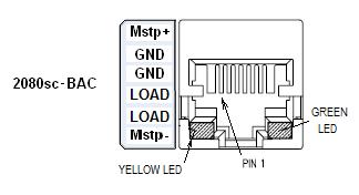
The module plugs into, and communicates with, a controller in the Micro800 family. Communication I/O signals are connected to the module through a 6-pin terminal block and an RJ-45 connector:
1.5.1 Serial I/O RJ-45 Connector
NOTE Pins in following table are listed from 6 to 1 to match connector
on front panel of module.
User’s Manual Pub. 0300274-01 Rev. A.0
Chapter 1: Module Overview |
1-7 |
|
|
The six-pin Connector pinouts are as follows:
Pin |
Signal |
|
|
6 |
MSTP+ |
|
|
5 |
GND |
|
|
4 |
GND |
|
|
3 |
LOAD- |
|
|
2 |
LOAD+ |
|
|
1 |
MSTP- |
|
|
1.5.2 Ethernet Connector
The Ethernet connector has a default MAC address that may be changed during setup. The Ethernet connector may be used as an external communication port to a personal computer or to another BACnet module. The Ethernet connector is also used to configure the module.
The default IP address for the module is 169.254.3.3. If the module is already configured, software is available for you to detect the address. See Chapter 3, Configuring the Module Using Software.
Pinouts for the connector (crossover) are:
2080sc-BACnet |
Personal Computer |
Module |
|
|
|
1 TX+ |
8 Not connected |
2 TX- |
7 Not connected |
3 RX+ |
6 TX- |
4 Not connected |
5 Not connected |
5 Not connected |
4 Not connected |
6 RX- |
3 TX+ |
7 Not connected |
2 RX- |
8 Not connected |
1 RX+ |
|
|
User’s Manual Pub. 0300274-01 Rev. A.0
1-8 |
Chapter 1: Module Overview |
|
|
Section 1.6 LED Indicator
A single LED indicator is provided with the module. The LED is green for ON. The LED blinks in case of a fault.
Section 1.7 Software Upgrade
The module software can be upgraded in the field.
Section 1.8 Module DC Power Specifications
The controller provides two Power Supplies to the module:
3.3 Volts (3.0 V Min, 3.6 V Max), Current Rating: 40 mA
24 Volts (20.4 V Min, 26.4 V Max), Current Rating: 50 mA
You may not use an external power source to power the module. Refer to the specifications in the Appendix for further information.
Section 1.9 Module Chassis Earth Ground
The Micro800 controller does not have a chassis (earth) ground. The 2080scBACnet module connects to an isolated ground, ISO-GND, which is exclusive to the external communication interfaces. The purpose of the isolated ground is to prevent possible interference on the I/O channels from permanently damaging the module itself.
User’s Manual Pub. 0300274-01 Rev. A.0
Chapter 2
Installation and Wiring
Section 2.1 Insert Module into Controller
Follow the instructions to insert and secure the plug-in module to the controller.
WARNING Electrostatic discharge can damage integrated circuits or semiconductors if you touch bus connector pins. Follow these guidelines when you handle the module:
Touch a grounded object to discharge static potential.
Wear an approved wrist-strap grounding device.
Do not touch connectors or pins on component boards.
Do not touch circuit components inside the module.
If available, use a static-safe work station.
When not in use, keep the module in its static-shield box.
WARNING Cet équipement est sensible aux décharges électrostatiques, lesquelles peuvent entraîner des dommages internes et nuire à son bon onctionnement.
Conformez-vous aux directives suivantes lorsque vous manipulez cet équipement :
Touchez un objet mis à la terre pour vous décharger de toute électricité statique éventuelle ;
Portez au poignet un bracelet antistatique agréé ;
Ne touchez pas les connecteurs ni les broches figurant sur les cartes des composants ;
Ne touchez pas les circuits internes de l’équipement ;
Utilisez si possible un poste de travail antistatique ;
Lorsque vous n’utilisez pas l’équipement, stockez-le dans un emballage antistatique.
User’s Manual Pub. 0300274-01 Rev. A.0
Loading...