


User’s Manual Pub. 0300266-01 Rev. A
Point IO™
4 Universal Analog Input Module
Catalog Number: 1734sc-IF4U
ii |
Point IO™ 4 Channel Universal Analog Input Module |
Important Notes
1.Please read all the information in this owner’s guide before installing the product.
2.The information in this owner's guide applies to hardware Series A and firmware version 1.00 or later.
3.This guide assumes that the reader has a full working knowledge of the relevant processor.
Notice
The products and services described in this owner's guide are useful in a wide variety of applications. Therefore, the user and others responsible for applying the products and services described herein are responsible for determining their acceptability for each application. While efforts have been made to provide accurate information within this owner's guide, Spectrum Controls assumes no responsibility for the accuracy, completeness, or usefulness of the information herein.
Under no circumstances will Spectrum Controls be responsible or liable for any damages or losses, including indirect or consequential damages or losses, arising out of either the use of any information within this owner's guide or the use of any product or service referenced herein.
No patent liability is assumed by Spectrum Controls with respect to the use of any of the information, products, circuits, programming, or services referenced herein.
The information in this owner's guide is subject to change without notice.
Limited Warranty
Spectrum Controls warrants that its products are free from defects in material and workmanship under normal use and service, as described in Spectrum Controls literature covering this product, for a period of 1 year. The obligations of Spectrum Controls under this warranty are limited to replacing or repairing, at its option, at its factory or facility, any product which shall, in the applicable period after shipment, be returned to the Spectrum Controls facility, transportation charges prepaid, and which after examination is determined, to the satisfaction of Spectrum Controls, to be thus defective.
This warranty shall not apply to any such equipment which shall have been repaired or altered except by Spectrum Controls or which shall have been subject to misuse, neglect, or accident. In no case shall the liability of Spectrum Controls exceed the purchase price. The aforementioned provisions do not extend the original warranty period of any product which has either been repaired or replaced by Spectrum Controls.
User’s Manual Pub. 0300266-01 Rev. A
|
iii |
Table of Contents |
|
IMPORTANT NOTES............................................................................................................................................ |
II |
NOTICE .............................................................................................................................................................. |
II |
LIMITED WARRANTY .......................................................................................................................................... |
II |
CHAPTER 1 MODULE OVERVIEW ..................................................................................................................... |
1 1 |
SECTION 1.1 GENERAL DESCRIPTION .............................................................................................................................. |
1 1 |
SECTION 1.2 INPUT TYPES............................................................................................................................................ |
1 1 |
SECTION 1.3 DATA FORMATS ....................................................................................................................................... |
1 2 |
SECTION 1.4 FILTER FREQUENCIES ................................................................................................................................ |
1 2 |
SECTION 1.5 HARDWARE FEATURES .............................................................................................................................. |
1 2 |
1.5.1 LED Indicators ........................................................................................................................................... |
1 3 |
SECTION 1.6 SYSTEM OVERVIEW ................................................................................................................................... |
1 4 |
1.6.1 Module Power up ..................................................................................................................................... |
1 5 |
1.6.2 Module Operation..................................................................................................................................... |
1 5 |
CHAPTER 2 INSTALLATION AND WIRING.......................................................................................................... |
2 1 |
SECTION 2.1 COMPLIANCE TO EUROPEAN UNION DIRECTIVES............................................................................................. |
2 1 |
2.1.1 EMC Directive............................................................................................................................................ |
2 1 |
2.1.2 Low Voltage Directive ............................................................................................................................... |
2 1 |
SECTION 2.2 POWER REQUIREMENTS ............................................................................................................................ |
2 1 |
SECTION 2.3 GENERAL CONSIDERATIONS ........................................................................................................................ |
2 2 |
2.3.1 Hazardous Location Considerations.......................................................................................................... |
2 2 |
2.3.2 Prevent Electrostatic Discharge ................................................................................................................ |
2 3 |
2.3.3 Remove Power .......................................................................................................................................... |
2 3 |
2.3.4 Selecting a Location .................................................................................................................................. |
2 3 |
SECTION 2.4 MOUNTING ............................................................................................................................................. |
2 3 |
2.4.1 Before You Begin....................................................................................................................................... |
2 3 |
2.4.2 Install Mounting Base ............................................................................................................................... |
2 5 |
2.4.3 Install the I/O Module............................................................................................................................... |
2 5 |
2.4.4 Install the Removable Terminal Block (RTB) ............................................................................................. |
2 6 |
2.4.5 Remove a Mounting Base ......................................................................................................................... |
2 6 |
2.4.6 Install a 1734 TOPS Base .......................................................................................................................... |
2 7 |
2.4.7 Remove a 1734 TOPS Base ....................................................................................................................... |
2 7 |
SECTION 2.5 FIELD WIRING CONNECTIONS...................................................................................................................... |
2 7 |
2.5.1 Wiring Diagram ........................................................................................................................................ |
2 8 |
CHAPTER 3 CONFIGURING THE 1734SC IF4U USING RSLOGIX 5000................................................................... |
3 1 |
SECTION 3.1 INTRODUCTION ........................................................................................................................................ |
3 1 |
SECTION 3.2 ABOUT COMMUNICATIONS......................................................................................................................... |
3 1 |
SECTION 3.3 USE GENERIC PROFILE ............................................................................................................................... |
3 2 |
3.3.1 Add a Local Ethernet Bridge Module ........................................................................................................ |
3 3 |
3.3.2 Add a Remote Ethernet Point IO Adapter ................................................................................................. |
3 4 |
3.3.3 Add the Generic Point IO Module ............................................................................................................. |
3 6 |
SECTION 3.4 USE ADD ON PROFILE.............................................................................................................................. |
3 7 |
3.4.1 Installing the Add On profile..................................................................................................................... |
3 8 |
3.4.2 Adding the IF4U Module To Your Logix Project ........................................................................................ |
3 8 |
SECTION 3.5 MODULE CONFIGURATION....................................................................................................................... |
3 10 |
3.5.1 Channel Configuration Details ................................................................................................................ |
3 12 |
SECTION 3.6 READ INPUT DATA ................................................................................................................................. |
3 16 |
3.6.1 Input Assembly Status Bit Definitions ..................................................................................................... |
3 17 |
APPENDIX A MODULE SPECIFICATIONS............................................................................................................ |
A 1 |
User’s Manual Pub. 0300266-01 Rev. A
iv |
Point IO™ 4 Channel Universal Analog Input Module |
PREFACE
Read this preface to familiarize yourself with the rest of the manual. This preface covers the following topics:
Who should use this manual
How to use this manual
Related publications
Conventions used in this manual
Rockwell Automation support
Who Should Use This Manual
Use this manual if you are responsible for designing, installing, programming, or troubleshooting control systems that use Allen-Bradley I/O and/or compatible controllers, such as CompactLogix and ControlLogix.
How to Use This Manual
As much as possible, we organized this manual to explain, in a task-by-task manner, how to install, configure, program, operate and troubleshoot a control system using the 1734sc-IF4U.
Related Documentation
The table below provides a listing of publications that contain important information about Allen-Bradley PLC systems.
For |
Refer to this |
Allen-Bradley |
|
Document |
Pub. No. |
A description and |
POINT I/O Selection |
1734-SG001 |
overview of the 1734 and |
Guide |
|
1734D series POINT I/O |
|
|
modules |
|
|
and compatible control |
|
|
platforms. Also includes |
|
|
an overview of how to |
|
|
specify |
|
|
a POINT I/O system. |
|
|
Information about how to |
Expansion Power |
1734-IN058 |
install the 1734-EP24DC, |
Supply Installation |
|
Series B POINT I/O 24V |
Instructions |
|
dc Expansion Power |
|
|
Supply. |
|
|
Information about how to |
Wiring Base Assembly |
1734-IN511 |
install 1734-TB and -TBS |
Installation Instructions |
|
POINT I/O Wiring Base |
|
|
Assemblies |
|
|
Information about how to |
Wiring Base Assembly |
1734-IN013 |
install 1734-TB3 and - |
Installation Instructions |
|
TB3S POINT I/O Wiring |
|
|
Base |
|
|
Assemblies. |
|
|
User’s Manual Pub. 0300266-01 Rev. A

v
If you would like a manual, you can:
Download a free electronic version from the internet at www.theautomationbookstore.com
Purchase a printed manual by:
o Contacting your local distributor or Rockwell Automation representative
o Visiting www.theautomationbookstore.com and placing your order
oCalling 1.800.963.9548 (USA/Canada) or 001.330.725.1574 (Outside USA/Canada)
Conventions
Used in This
Manual
The following conventions are used throughout this manual:
Bulleted lists (like this one) provide information not procedural steps.
Numbered lists provide sequential steps or hierarchical information.
Italic type is used for emphasis
Bold type identifies headings and sub-headings
!
Attention Are used to identify critical information to the reader
User’s Manual Pub. 0300266-01 Rev. A
vi |
Point IO™ 4 Channel Universal Analog Input Module |
User’s Manual Pub. 0300266-01 Rev. A
Chapter 1 Module Overview
The 1734sc-IF4U module has four analog input channels that support current, voltage, RTD, resistance and thermocouple input types. This chapter includes information about:
General description
Input types
Data Formats
Filter frequencies
Hardware Features
System overview and module operation
Section 1.1
General
Description
The IF4U module digitally converts and stores analog data for each configured input.
Each input channel can be independently configured for input type, data format and filter
frequency.
Section 1.2
Input Types
The IF4U module supports the following input types.
Table 1-1 (Input Types) |
|
|
|
Input Type |
|
Range |
|
E Type Thermocouple |
|
-270 to 1000 ˚C |
(-454 to 1832 ˚F) |
J Type Thermocouple |
|
-210 to 1200 ˚C |
(-346 to 2192 ˚F) |
K Type Thermocouple |
|
-270 to 1370 ˚C |
(-454 to 2498 ˚F) |
T Type Thermocouple |
|
-270 to 400 ˚C |
(-270 to 752 ˚F) |
100 Ω Pt α 0.385 |
|
-200 to 850 ˚C |
(-328 to 1562 ˚F) |
1000 Ω Pt α 0.385 |
|
-200 to 850 ˚C |
(-328 to 1562 ˚F) |
100 Ω Pt α 0.3916 |
|
-200 to 630 ˚C |
(-328 to 1166 ˚F) |
1000 Ω Pt α 0.3916 |
|
-200 to 630 ˚C |
(-328 to 1166 ˚F) |
Resistance |
|
0 to 3000 Ω |
|
|
|
+/- 50 mV |
|
|
|
+/- 100 mV |
|
Voltage |
|
+/- 1 V |
|
|
0 to 5V |
|
|
|
|
1 to 5V |
|
|
|
+/- 10V |
|
|
|
0 to 10V |
|
Current |
|
4 to 20 mA |
|
|
0 to 20 mA |
|
|
|
|
|
|
CJC |
|
-25 to 85 ˚C |
|
User’s Manual Pub. 0300266-01 Rev. A
1-2 |
Point IO™ 4 Channel Universal Analog Input Module |
Section 1.3
Data Formats
For each channel the data can be configured for:
Engineering Units x1
Engineering Units x10
Scaled-for-PID
Raw/proportional counts
Section 1.4 Filter Frequencies
The module uses a notch filter to provide noise rejection for each input channel. The filter for each channel is programmable allowing you to select from 4 different filter options:
4.17 Hz
16.7 Hz
62 Hz
470 Hz
Section 1.5
Hardware
Features
Channels are wired as differential inputs.
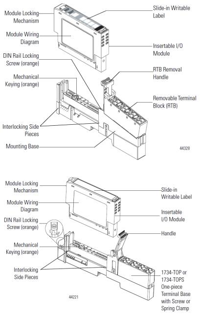
Module configuration is done via the controller’s programming software. The module configuration is stored in the memory of the controller. Refer to your controller’s user manual for more information. The illustration below shows the module’s hardware features.
User’s Manual Pub. 0300266-01 Rev. A
Chapter 1: Module Overview |
1-3 |
Figure 1
Figure 2
1.5.1 LED Indicators
The 1734 analog HART module uses several LEDs to show operational status. The status LEDs are defined below:
Table 1-2 (LED Status Indicators)
Indicator |
State |
Description |
|
|
|
Module |
Off |
No power applied to device |
Status |
Solid Green |
Device operating normally |
|
|
|
User’s Manual Pub. 0300266-01 Rev. A
1-4 |
Point IO™ 4 Channel Universal Analog Input Module |
|
|||
|
|
|
|
|
|
|
|
Indicator |
State |
Description |
|
|
|
|
|
|
|
|
|
|
|
Device needs commissioning due to configuration missing, |
|
|
|
|
Flashing |
incomplete, or incorrect. |
|
|
|
|
Green |
NOTE: The module always sets default values for invalid |
|
|
|
|
|
configurations. Therefore, this status will not be shown. |
|
|
|
|
|
|
|
|
|
|
Flashing Red |
Not used with this module. |
|
|
|
|
|
|
|
|
|
|
|
Recoverable fault. |
|
|
|
|
Solid Red |
ADC communications fault, or backplane communications |
|
|
|
|
|
error. |
|
|
|
|
|
|
|
|
|
|
Flashing |
Device is in self-test mode. |
|
|
|
|
Red/Green |
This is only used during factory test and power-up. |
|
|
|
|
|
|
|
|
|
|
|
Channel disabled. Will remain off after power-up until |
|
|
|
|
Off |
connection established. Analog processing will not take place |
|
|
|
|
|
if no connection is made. |
|
|
|
|
|
|
|
|
|
|
Solid Green |
Normal (channel scanning inputs) |
|
|
|
|
|
|
|
|
|
|
Flashing |
Calibration mode. |
|
|
|
|
Green |
||
|
|
Channel |
|
|
|
|
|
|
|
|
|
|
|
|
Major channel fault. |
||
|
|
Status |
|
||
|
|
|
Solid Red |
ADC communications fault. |
|
|
|
|
Analog values will remain at current state until fault has |
||
|
|
|
|
||
|
|
|
|
recovered. |
|
|
|
|
|
|
|
|
|
|
Flashing Red |
Channel at end of range |
|
|
|
|
|
|
|
|
|
|
Flashing |
Displayed during power-up. |
|
|
|
|
Red/Green |
||
|
|
|
|
|
|
|
|
|
|
|
|
|
|
|
Off |
Device not powered/Not online. |
|
|
|
|
|
|
|
|
|
|
Solid Green |
Device operational AND online AND connected. |
|
|
|
|
|
|
|
|
|
|
Flashing |
Device operational AND online but not connected. |
|
|
|
|
-OR- |
||
|
|
|
Green |
||
|
|
|
Device online AND device needs commissioning. |
||
|
|
Network |
|
||
|
|
|
|
|
|
|
|
|
Minor fault AND/OR connection timeout AND/OR no |
||
|
|
Status |
Flashing Red |
||
|
|
|
|
network power. |
|
|
|
|
Solid Red |
Critical fault OR critical link failure. |
|
|
|
|
|
|
|
|
|
|
Flashing |
Communication faulted and received an identify comm fault |
|
|
|
|
request - long protocol. |
||
|
|
|
Red/Green |
||
|
|
|
Also displayed during power-up. |
||
|
|
|
|
||
|
|
|
|
|
|
Section 1.6 System Overview
The module communicates to the controller via a 1734 Control Net, Device Net or Ethernet adapter. The module receives 5 and 24V dc power through the bus interface.
User’s Manual Pub. 0300266-01 Rev. A
Chapter 1: Module Overview |
1-5 |
1.6.1 Module Power-up
At power-up, the module performs a check of its internal circuits, memory, and basic functions. If no faults are found during power-up diagnostics, the module status LED is turned on.
After power-up checks are complete, the module waits for valid channel configuration data. If an invalid configuration is detected, the module will generate a PLC fault. Once a channel is properly configured and enabled, it continuously converts the input data to a value within the range selected for that channel.
1.6.2 Module Operation
The 1734sc-IF4U module provides four independent analog input channels. Each channel includes four selectable filter settings and can be configured for voltage, thermocouple, current, resistance or RTD input types.
The 1734sc-IF4U module utilizes a 20-bit Sigma-Delta ADC (Analog to Digital Converter) to achieve 18-bit resolution. Inputs to the ADC are first multiplexed through analog switches then buffered by a precision, low offset and drift, programmable gain amplifier. The ADC also provides the programmable current source used in resistive measurements.
The 1734sc-IF4U plug-in module communicates over its isolated CAN Bus interface through the module backplane. The 1734 network adapter then communicates to the PLC controller. See the block diagram below.
Isolation |
|
|
|
|
|
|
|
|
Barrier |
|
|
|
|
|
|
|
|
|
|
|
|
|
|
Analog_0 |
|
Voltage / Current (4 chs) |
|
I |
|
|
|
|
Analog_1 |
Protection, |
|
|
s |
|
|
|
ADC |
|
|
|
|
|
|
SPI Interface |
Analog_2 |
Filtering, |
Thermocouple (3 chs) |
||
CAN |
o |
|
|
|||||
|
|
|
Current Srcs |
Analog |
|
|||
Bus |
l |
Isolated |
|
|
|
|||
Processor |
SPI Interface |
|
Switch |
RTD / Resistance (2/4 chs) |
||||
and |
a |
CAN Bus |
|
|||||
|
|
Matrix, |
|
|||||
+5VDC |
t |
|
|
PGA_Interrupt |
|
CJC (1 ch) |
||
|
|
|
PGA |
|||||
|
i |
|
|
|
|
|
||
|
Controls |
|
|
|
|
|
|
|
Point Bus |
o |
|
|
LEDs |
|
|
|
|
n |
|
|
|
|
|
|
||
Low |
|
|
|
Controls and Status |
|
|||
|
|
|
|
|
||||
|
|
|
|
|
|
|||
|
|
Input Power |
|
|
|
|
|
|
Isolation |
|
Interrupt |
|
|
System |
|
|
|
|
and |
|
CLK |
|
|
|
||
|
|
Clock |
|
|
|
|||
Barrier |
|
System_Reset |
|
|
|
|
||
|
|
|
|
|
Generator |
Notes: |
|
|
|
|
|
|
|
|
|
|
|
+24VDC |
Power Supplies |
+15VDC ±3VDC |
|
1) I/O’s are ESD protected |
||||
+3.3VDC ±2% |
|
|
|
|||||
GND |
|
And |
GND |
|
|
|
|
|
|
|
Power Monitor |
15VDC ±3VDC |
|
|
|
||
User’s Manual Pub. 0300266-01 Rev. A
1-6 |
Point IO™ 4 Channel Universal Analog Input Module |
User’s Manual Pub. 0300266-01 Rev. A
Chapter 2
Installation and Wiring
This chapter will cover:
Compliance to European union directives
Power requirements
General considerations
Mounting
Field wiring connections
Section 2.1 Compliance to European Union Directives
This product is approved for installation within the European Union and EEA regions. It has been designed and tested to meet the following directives.
2.1.1 EMC Directive
The 1734sc-IF4U module is tested to meet Council Directive 89/336/EEC Electromagnetic Compatibility (EMC) and the following standards, in whole or in part, documented in a technical construction file:
IEC 61000-6-4 Electromagnetic compatibility (EMC) - Part 6-4: Generic standards - Emission standard for industrial environments
IEC 61000-6-2 Electromagnetic compatibility (EMC) – Part 6-2: Generic standards – Immunity for industrial environments
This product is intended for use in an industrial environment.
2.1.2 Low Voltage Directive
This product is tested to meet Council Directive 73/23/EEC Low Voltage, by applying the safety requirements of EN 61131-2Programmable Controllers, Part 2 – Equipment Requirements and Tests. For specific information required by EN61131-2, see the appropriate sections in this publication, as well as the following Allen-Bradley publications:
Industrial Automation, Wiring and Grounding Guidelines for Noise Immunity, publication 1770-4.1
Automation Systems Catalog, publication B113
Section 2.2 Power Requirements
The module receives power through the bus interface from the +5V dc/+24V dc system power supply. The maximum current drawn by the module is shown in the table below.
User’s Manual Pub. 0300266-01 Rev. A

2-2 |
Point IO™ 4 Channel Universal Analog Input Module |
5 VDC |
24 VDC |
15 mA (max) |
20 mA (max) |
Use the table below to determine the maximum number of IF4U modules that can be installed in a MicroLogix system.
Section 2.3 General Considerations
1734 I/O is suitable for use in an industrial environment when installed in accordance with these instructions. Specifically, this equipment is intended for use in clean, dry environments Pollution degree 21 and to circuits not exceeding Over Voltage Category II2(IEC 60664-1)3.
2.3.1 Hazardous Location Considerations
This equipment is suitable for use in Class I, Division 2, Groups A, B, C, D or nonhazardous locations only. The following WARNING statement applies to use in hazardous locations.
!
Attention
EXPLOSION HAZARD
Substitution of components may impair suitability for Class I, Division 2.
Do not replace components or disconnect equipment unless power has been switched off or the area is known to be nonhazardous.
Do not connect or disconnect components unless power has been switched off or the area is known to be non-hazardous.
This product must be installed in an IP54 rated enclosure.
All wiring must comply with N.E.C. article 501-4(b).
1Pollution Degree 2 is an environment where, normally, only non-conductive pollution occurs except that occasionally a temporary conductivity caused by condensation shall be expected.
2Over Voltage Category II is the load level section of the electrical distribution system. At this level transient voltages are controlled and do not exceed the impulse voltage capability of the product’s insulation.
3Pollution Degree 2 and Over Voltage Category II are International Electrotechnical Commission (IEC) designations.
User’s Manual Pub. 0300266-01 Rev. A

Chapter 2: Installation and Wiring |
2-3 |
2.3.2 Prevent Electrostatic Discharge
!
Attention
Electrostatic discharge can damage integrated circuits or semiconductors if you touch analog I/O module bus connector pins or the terminal block on the input module. Follow these guidelines when you handle the module:
Touch a grounded object to discharge static potential.
Wear an approved wrist-strap grounding device.
Do not touch the bus connector or connector pins.
Do not touch circuit components inside the module.
If available, use a static-safe work station.
When it is not in use, keep the module in its static-shield bag.
2.3.3 Remove Power
!
Attention
Remove power before removing or inserting this module. When you remove or insert a module with power applied, an electrical arc may occur. An electrical arc can cause personal injury or property damage by:
Sending an erroneous signal to your system’s field devices, causing unintended machine motion
Causing an explosion in a hazardous environment
Electrical arcing causes excessive wear to contacts on both the module and its mating connector and may lead to premature failure.
2.3.4 Selecting a Location
Reducing Noise
Most applications require installation in an industrial enclosure to reduce the effects of electrical interference. Analog inputs are highly susceptible to electrical noise. Electrical noise coupled to the analog inputs will reduce the performance (accuracy) of the module. Group your modules to minimize adverse effects from radiated electrical noise and heat. Consider the following conditions when selecting a location for the analog module. Position the module:
Away from sources of electrical noise such as hard-contact switches, relays, and AC motor drives
Away from modules which generate significant radiated heat. Refer to the module’s heat dissipation specification.
In addition, route shielded, twisted-pair analog input wiring away from any high voltage I/O wiring.
Section 2.4
Mounting
2.4.1 Before You Begin
Note that this series C product can be used with the following:
ControlNet and EtherNet/IP adapters ONLY, using RSLogix 5000 software, version 11 or later
See the figures to familiarize yourself with major parts of the module, noting that the
User’s Manual Pub. 0300266-01 Rev. A
 Loading...